US5406930A - Outdoor cooking device - Google Patents
Outdoor cooking deviceDownload PDFInfo
- Publication number
- US5406930A US5406930AUS08/103,770US10377093AUS5406930AUS 5406930 AUS5406930 AUS 5406930AUS 10377093 AUS10377093 AUS 10377093AUS 5406930 AUS5406930 AUS 5406930A
- Authority
- US
- United States
- Prior art keywords
- cooking device
- cover
- composite
- layers
- metal foil
- Prior art date
- Legal status (The legal status is an assumption and is not a legal conclusion. Google has not performed a legal analysis and makes no representation as to the accuracy of the status listed.)
- Expired - Lifetime
Links
- 238000010411cookingMethods0.000titleclaimsabstractdescription88
- 239000002131composite materialSubstances0.000claimsabstractdescription70
- 239000011888foilSubstances0.000claimsabstractdescription43
- 229910052751metalInorganic materials0.000claimsabstractdescription40
- 239000002184metalSubstances0.000claimsabstractdescription40
- 239000003610charcoalSubstances0.000claimsabstractdescription20
- 238000012546transferMethods0.000claimsabstractdescription6
- 239000010410layerSubstances0.000claimsdescription49
- ATUOYWHBWRKTHZ-UHFFFAOYSA-NPropaneChemical compoundCCCATUOYWHBWRKTHZ-UHFFFAOYSA-N0.000claimsdescription6
- XAGFODPZIPBFFR-UHFFFAOYSA-NaluminiumChemical compound[Al]XAGFODPZIPBFFR-UHFFFAOYSA-N0.000claimsdescription6
- 229910052782aluminiumInorganic materials0.000claimsdescription5
- 239000012530fluidSubstances0.000claimsdescription5
- 238000010438heat treatmentMethods0.000claimsdescription5
- 239000000853adhesiveSubstances0.000claimsdescription3
- 230000001070adhesive effectEffects0.000claimsdescription3
- 238000004891communicationMethods0.000claimsdescription3
- 239000001294propaneSubstances0.000claimsdescription3
- 229910000838Al alloyInorganic materials0.000claimsdescription2
- 239000002356single layerSubstances0.000claimsdescription2
- 238000013022ventingMethods0.000claimsdescription2
- 230000000052comparative effectEffects0.000description11
- 239000000446fuelSubstances0.000description4
- 239000004820Pressure-sensitive adhesiveSubstances0.000description3
- 238000012360testing methodMethods0.000description3
- 238000007493shaping processMethods0.000description2
- 229910000831SteelInorganic materials0.000description1
- 238000010276constructionMethods0.000description1
- 239000007788liquidSubstances0.000description1
- 238000005259measurementMethods0.000description1
- 229910052573porcelainInorganic materials0.000description1
- 238000002360preparation methodMethods0.000description1
- 239000010959steelSubstances0.000description1
Images


Classifications
- A—HUMAN NECESSITIES
- A47—FURNITURE; DOMESTIC ARTICLES OR APPLIANCES; COFFEE MILLS; SPICE MILLS; SUCTION CLEANERS IN GENERAL
- A47J—KITCHEN EQUIPMENT; COFFEE MILLS; SPICE MILLS; APPARATUS FOR MAKING BEVERAGES
- A47J37/00—Baking; Roasting; Grilling; Frying
- A47J37/06—Roasters; Grills; Sandwich grills
- A47J37/07—Roasting devices for outdoor use; Barbecues
- A47J37/0704—Roasting devices for outdoor use; Barbecues with horizontal fire box
Definitions
- the present inventionrelates to outdoor cooking devices and more particularly, to outdoor cooking devices such as an outdoor barbeque oven.
- a popular form of food preparation during warm weatheris the outdoor barbeque.
- foodis prepared by cooking it on a grill of an outdoor barbeque oven.
- Such barbeque ovensare usually heated with an ignitable fuel source such as charcoal, propane gas or a liquid fuel.
- Such cooking arrangementstypically include a metal cover which fits over the cooking surface. In use, such covers become very hot which makes them difficult to handle and pose a burning hazard.
- charcoal grillsparticularly large charcoal grills, it is especially difficult to obtain uniform heating across the grill surface unless a large amount of charcoal is used to cover the entire area under the grill. However, when a large amount of charcoal is used the grill can become too hot for cooking. As a result, it is necessary to wait until the fire dies down thus wasting energy and cooking time.
- the inventionprovides an outdoor cooking device which includes a base, a cover and a multilayer heat insulating composite.
- the baseincludes a food cooking surface and means for supporting an ignitable heat source for heating the cooking surface.
- the coveris supported on the base and encloses an open space facing the cooking surface.
- the compositeis on an inside surface of the cover and is effective for distributing heat more uniformly over the cooking surface and reducing transfer of heat to an outer surface of the cover.
- the compositeincludes at least two layers of metal foil and at least one of the layers has a plurality of projections thereon in point contact with an adjacent layer of the metal foil so as to provide a plurality of air spaces therebetween.
- the compositecan include three layers of metal foil, four layers of metal foil or more than four layers of metal foil. At least one of the layers of metal foil preferably includes a pattern of embossments therein separating the layers to allow thermal convection in spaces therebetween and provide thermal conduction at spaced-apart points of contact between the embossments and an adjacent one of the layers. Although each of the layers of metal foil can include a pattern of embossments, it is preferred that one of the layers of the metal foil in contact with the inside surface of the cover is an outermost layer which is flat.
- the layers of metal foilcan be of any suitable metal such as aluminum or an aluminum alloy. Preferably, the layers of metal foil are not metallurgically bonded together and the composite consists entirely of aluminum foil.
- the compositesubstantially covers all of the inside surface of the cover.
- the compositecan include a plurality of discrete sections with one of the sections being located on a center of the inside surface of the cover and another one of the sections being located adjacent a lower edge of the inside surface of the cover.
- the compositecan include a flat metal foil attached to the inside surface of the cover by any suitable means such as pressure sensitive adhesive or the composite can be attached by a mechanical connection such as bolts, screws, etc.
- a second multilayered heat insulating compositecan be provided on the inner surface of the base and the second composite can be attached to the inner surface of the base in the same manner that the first composite is attached to the cover.
- the basecan include a charcoal supporting grate located above a bottom wall of the base and the second composite can extend complete around the inner surface of the base and extend between the charcoal supporting grate and an upper edge of the base.
- the base and covercan each be of a single layer of metal such as a porcelain coated sheet of steel.
- the covercan include one or more openings therethrough for venting of the cooking device in which case the composite includes holes therethrough in fluid communication with the openings in the cover.
- the ignitable heat sourcecan comprise charcoal briquettes which can be supported on a suitable grate in the base or the ignitable heat source can comprise another type of fuel such as propane gas distributed beneath the cooking surface by a suitable gas distributing burner arrangement.
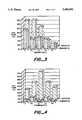
- FIG. 1shows an outdoor cooking device in accordance with the invention
- FIG. 2shows a multilayer heat insulating composite in accordance with the invention
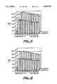
- FIG. 3shows a comparison of average temperatures measured by thermocouples 1-5 in FIG. 1 in a cooking device in accordance with the invention compared to a cooking device without the multilayer heat insulating composite according to the invention;
- FIG. 4shows a comparison of average temperatures across the cooking surface measured by thermocouples 7, 8, 2, 9 and 10 in FIG. 1 in a cooking device in accordance with the invention compared to a cooking device without the multilayer heat insulating composite according to the invention;
- FIG. 5shows a comparison of temperatures measured by thermocouple 1 in FIG. 1 in a cooking device in accordance with the invention compared to a cooking device without the multilayer heat insulating composite according to the invention
- FIG. 6shows a comparison of temperatures measured by thermocouple 2 in FIG. 1 in a cooking device in accordance with the invention compared to a cooking device without the multilayer heat insulating composite according to the invention
- FIG. 7shows a comparison of temperatures measured by thermocouple 3 in FIG. 1 in a cooking device in accordance with the invention compared to a cooking device without the multilayer heat insulating composite according to the invention
- FIG. 8shows a comparison of temperatures measured by thermocouple 4 in FIG. 1 in a cooking device in accordance with the invention compared to a cooking device without the multilayer heat insulating composite according to the invention
- FIG. 9shows a comparison of temperatures measured by thermocouple 7 in FIG. 1 in a cooking device in accordance with the invention compared to a cooking device without the multilayer heat :insulating composite according to the invention;
- FIG. 10shows a comparison of temperatures measured by thermocouple 8 in FIG. 1 in a cooking device in accordance with the invention compared to a cooking device without the multilayer heat insulating composite according to the invention;
- FIG. 11shows a comparison of temperatures measured by thermocouple 9 in FIG. 1 in a cooking device in accordance with the invention compared to a cooking device without the multilayer heat insulating composite according to the invention;
- FIG. 12shows a comparison of temperatures measured by thermocouple 10 in FIG. 1 in a cooking device in accordance with the invention compared to a cooking device without the multilayer heat insulating composite according to the invention;
- FIG. 13shows a comparison of differences in temperatures measured by thermocouples 3 and 4 in FIG. 1 in a cooking device in accordance with the invention compared to a cooking device without the multilayer heat insulating composite according to the invention.
- FIG. 14shows a comparison of temperatures measured by thermocouple 5 in FIG. 1 in a cooking device in accordance with the invention compared to a cooking device without the multilayer heat insulating composite according to the invention.
- the inventionprovides an outdoor cooking device which includes a base, a cover and a multilayer heat insulating composite.
- the baseincludes a food cooking surface and a means for supporting an ignitable heat source for heating the cooking surface.
- the coveris supported on the base and encloses an open space facing the cooking surface.
- the multilayer heat insulating compositeincludes a plurality of layers of metal foil for distributing heat more uniformly over the cooking surface and reducing transfer of heat to an outer surface of the cover.
- FIG. 1shows an outdoor cooking device 1 in accordance with the invention.
- the device 1includes a base 2 and cover 3.
- the base 2includes a food cooking surface 4 such as a wire grill and means 5 such as a grate for supporting an ignitable heat source for heating the cooking surface 4.
- the cover 3can be pivotally supported on the base 2 and/or removable therefrom and the cover 3 includes an open space 6 facing the cooking surface 4.
- a multilayer heat insulating composite 7is provided on an inside surface 8 of the cover 3. As shown in FIG. 2, the composite 7 includes at least two layers 9 of metal foil and at least one of the layers has a plurality of projections 10 thereon in point contact with an adjacent layer of the metal foil so as to provide a plurality of air spaces 11 therebetween.
- One of the layers 12can be flat and a layer of adhesive 13 such as pressure sensitive adhesive can be provided on the flat layer 12 to facilitate attachment of the composite 7 to the inside surface 8 of the cover 3.
- An edge 14 of the composite 7can be secured together by any suitable means such as staples 15. Alternatively, the edge 14 can be perforated to interengage the various layers of metal foil or one layer of foil can wrap around the edges of the remaining foil layers.
- Each of the layers 9 of metal foilcan be provided with a pattern of embossments.
- one sheetcan have a pattern of embossments oriented at 90° and the adjacent sheet can have a pattern of embossments oriented at 22°. That is, the embossments can have the same spacing and heights but by orienting the pattern of embossments in different directions it is possible to stack the layers of metal foil such that the embossments do not coincide and nest in each other.
- the size and spacing of the embossmentscan be adjusted depending on the thickness of the metal foil. Typically, the heights of the embossments will be smaller for thicker metal foils and higher for thinner metal foils. As an example, a two mail aluminum foil can be embossed with a spacing of 0.200 inch between embossments and with a 0.035 inch height of embossments.
- the composite 7can include as few as two layers of foil but preferably includes at least three layers or more.
- the compositecan include an outermost flat metal foil which has a layer of pressure sensitive adhesive thereon.
- the composite 7it may be necessary to provide the composite 7 in more than one section with or without shaping means such as slits, perforations, cut-outs, etc.
- the composite 7can include a flat center section attached to the center of the inside surface of the cover and one or more additional circumferentially extending sections can be provided adjacent the lower edge of the cover.
- the center section of the compositecan be circular in shape and include a plurality of radially extending slits extending inwardly from the outer edge thereof to facilitate shaping the composite such that the outer edge bends downwardly along the sloped outer wall of the cover.
- the covercan include one or more vent openings and the composite 7 can include holes therethrough in fluid communication with the vent openings.
- the cooking device 1can also include a second composite 16 located on the inner wall of the base 2.
- the second composite 16is identical in construction to the composite 7.
- the second composite 16surrounds charcoal briquettes 17 supported on the grate 5 and the second composite 16 extends between the grate 5 and an upper edge of the base 2.
- the second composite 16preferably extends completely around the inner surface of the base 2.
- FIGS. 3-14show results of tests carried out in a cooking device of the type shown in FIG. 1 with and without the composite 7, 16 according to the invention.
- the composite used in the insulated grillincluded four aluminum metal foil layers, three of which were embossed and one of which was a flat layer adhesively bonded to the inside surfaces of the cover and base. Each of the aluminum foils had a thickness of two mils.
- Thermocouples T1-T10were located at the positions shown in FIG. 1. The tests were carried out by using two identical barbeque grills, one of which was insulated as shown in FIG. 1 and the other of which was uninsulated.
- charcoal briquetteswere arranged in symmetrical layers of 16-9-4-1 in both grills and the charcoal briquettes were taken from the same container. The top and bottom vents of both grills were fully opened to ensure optimum draft.
- the thermocouple leadswere connected to the corresponding terminals of a temperature measuring device. Equal amounts of lighter fluid were applied to both piles of charcoal and the charcoal was ignited after the charcoal was allowed to absorb the lighter fluid for two minutes. When the charcoal in both grills achieved a uniform white/gray appearance, the cooking grills and covers were placed on the base of each grill. Temperature readings were monitored every 10 minutes and the measurements are shown in FIGS. 3-14.
- the insulated grillprovided a much higher temperature across the cooking grill surface than the uninsulated grill.
- the insulated grill according to the inventioncan utilize the heat from a given quantity of charcoal in a much more efficient manner than an uninsulated grill.
- FIG. 3shows an average of the temperatures measured by thermocouples T1-T5.
- the results for the insulated grill in accordance with the inventionare shown behind the comparative results for an uninsulated grill.
- FIG. 4shows average temperatures of the cooking grill surface as measured by thermocouples T7, T8, T2, T9 and T10.
- the results for the insulated grill in accordance with the inventionare shown behind the comparative results for an uninsulated grill.
- FIG. 5shows measured temperatures for thermocouple T1 at time intervals of 10 minutes.
- the results for an insulated grill in accordance with the inventionare shown behind the comparative results for an uninsulated grill.
- FIG. 6shows measured temperatures for thermocouple T2 at time intervals of 10 minutes.
- the results for an insulated grill in accordance with the inventionare shown behind the comparative results for an uninsulated grill.
- FIG. 7shows measured temperatures for thermocouple T3 at time intervals of 10 minutes.
- the results for an insulated grill in accordance with the inventionare shown behind the comparative results for an uninsulated grill.
- FIG. 8shows measured temperatures for thermocouple T4 at time intervals of 10 minutes.
- the results for an insulated grill in accordance with the inventionare shown behind the comparative results for an uninsulated grill.
- FIG. 9shows measured temperatures for thermocouple T7 at time intervals of 10 minutes.
- the results for an insulated grill in accordance with the inventionare shown behind the comparative results for an uninsulated grill.
- FIG. 10shows measured temperatures for thermocouple T8 at time intervals of 10 minutes.
- the results for an insulated grill in accordance with the inventionare shown behind the comparative results for an uninsulated grill.
- FIG. 11shows measured temperatures for thermocouple T9 at time intervals of 10 minutes.
- the results for an insulated grill in accordance with the inventionare shown behind the comparative results for an uninsulated grill.
- FIG. 12shows measured temperatures for thermocouple T10 at time intervals of 10 minutes.
- the results for an insulated grill in accordance with the inventionare shown behind the comparative results for an uninsulated grill.
- FIG. 13shows differences in temperatures measured by thermocouples T3 and T4.
- the differences in temperatures between thermocouples T3 and T4 for an insulated grill in accordance with the inventionare shown behind the comparative results for an uninsulated grill.
- FIG. 14shows a comparison between temperatures measured by thermocouple T5.
- the temperatures recorded outside the top of the base of a grill insulated in accordance with the inventionare much lower than the measured temperatures for the same location in an uninsulated grill.
Landscapes
- Engineering & Computer Science (AREA)
- Food Science & Technology (AREA)
- Baking, Grill, Roasting (AREA)
- Control And Other Processes For Unpacking Of Materials (AREA)
- Food-Manufacturing Devices (AREA)
- Crushing And Pulverization Processes (AREA)
- Diaphragms For Electromechanical Transducers (AREA)
- Audible-Bandwidth Dynamoelectric Transducers Other Than Pickups (AREA)
- Constitution Of High-Frequency Heating (AREA)
- Cookers (AREA)
Abstract
Description
Claims (20)
Priority Applications (9)
| Application Number | Priority Date | Filing Date | Title |
|---|---|---|---|
| US08/103,770US5406930A (en) | 1993-08-10 | 1993-08-10 | Outdoor cooking device |
| ES94925227TES2115252T3 (en) | 1993-08-10 | 1994-08-10 | DEVICE FOR OUTDOOR COOKING. |
| EP94925227AEP0712478B1 (en) | 1993-08-10 | 1994-08-10 | Outdoor cooking device |
| DE69408327TDE69408327T2 (en) | 1993-08-10 | 1994-08-10 | GRILL FOR OUTDOOR USE |
| AT94925227TATE162885T1 (en) | 1993-08-10 | 1994-08-10 | GRILL FOR OUTDOOR USE |
| CA002169265ACA2169265C (en) | 1993-08-10 | 1994-08-10 | Outdoor cooking device |
| BR9407235ABR9407235A (en) | 1993-08-10 | 1994-08-10 | Device for outdoor cooking |
| PCT/US1994/008994WO1995004901A1 (en) | 1993-08-10 | 1994-08-10 | Outdoor cooking device |
| AU75229/94AAU678595B2 (en) | 1993-08-10 | 1994-08-10 | Outdoor cooking device |
Applications Claiming Priority (1)
| Application Number | Priority Date | Filing Date | Title |
|---|---|---|---|
| US08/103,770US5406930A (en) | 1993-08-10 | 1993-08-10 | Outdoor cooking device |
Publications (1)
| Publication Number | Publication Date |
|---|---|
| US5406930Atrue US5406930A (en) | 1995-04-18 |
Family
ID=22296958
Family Applications (1)
| Application Number | Title | Priority Date | Filing Date |
|---|---|---|---|
| US08/103,770Expired - LifetimeUS5406930A (en) | 1993-08-10 | 1993-08-10 | Outdoor cooking device |
Country Status (9)
| Country | Link |
|---|---|
| US (1) | US5406930A (en) |
| EP (1) | EP0712478B1 (en) |
| AT (1) | ATE162885T1 (en) |
| AU (1) | AU678595B2 (en) |
| BR (1) | BR9407235A (en) |
| CA (1) | CA2169265C (en) |
| DE (1) | DE69408327T2 (en) |
| ES (1) | ES2115252T3 (en) |
| WO (1) | WO1995004901A1 (en) |
Cited By (13)
| Publication number | Priority date | Publication date | Assignee | Title |
|---|---|---|---|---|
| EP0690268A3 (en)* | 1994-06-27 | 1996-09-25 | Bosch Siemens Hausgeraete | Household heating appliance |
| WO1998044835A1 (en)* | 1997-04-10 | 1998-10-15 | Atd Corporation | Electric barbecue grill |
| WO2001022854A1 (en)* | 1999-09-28 | 2001-04-05 | Cobb International Limited | Cooking apparatus |
| US6276356B1 (en) | 1998-07-09 | 2001-08-21 | Atd Corporation | Portable gas grill |
| EP1179311A1 (en)* | 2000-08-11 | 2002-02-13 | W.C. Bradley Company | Barbecue grill casting including insulative top cover |
| WO2002076272A2 (en) | 2001-03-26 | 2002-10-03 | Cobb International Limited | Cooking apparatus |
| US20030154971A1 (en)* | 2000-10-26 | 2003-08-21 | Wayne Chapman | One-piece hood for an outdoor grill |
| US20080210214A1 (en)* | 2007-03-01 | 2008-09-04 | Mark Wade | Outdoor grill cover |
| US20080230045A1 (en)* | 2007-03-21 | 2008-09-25 | Bruno Adrian A | Barbecue Grill |
| US20090165774A1 (en)* | 2008-01-02 | 2009-07-02 | Char-Broil, Llc | Temperature measurement means for cooking appliances |
| US20090308373A1 (en)* | 2008-06-16 | 2009-12-17 | In Zone, Inc. | Portable Insulated Grill |
| USD642416S1 (en) | 2008-06-16 | 2011-08-02 | Onward Multi-Corp, Inc. | Portable grill |
| US20220031119A1 (en)* | 2020-08-03 | 2022-02-03 | Kenyon International, Inc. | Multi-Layer Cooking Lid |
Families Citing this family (1)
| Publication number | Priority date | Publication date | Assignee | Title |
|---|---|---|---|---|
| DE10129370A1 (en)* | 2001-06-20 | 2003-09-11 | Robert Laskowski | Grill for meat and other foods with a folding protective screen for easy cleaning |
Citations (47)
| Publication number | Priority date | Publication date | Assignee | Title |
|---|---|---|---|---|
| GB126780A (en)* | 1918-05-13 | 1919-05-13 | George Herman Collier | Improvements in or connected with the Construction of Boxes or Cases or like objects and of the Floors, Roofs, Walls, Partitions or other Parts of Railway or other Vehicles or like objects. |
| US1815570A (en)* | 1928-08-07 | 1931-07-21 | Charles L Jones | Heat transfer apparatus |
| US1910703A (en)* | 1932-08-17 | 1933-05-23 | Grand Joseph M Le | Thermal insulation |
| US1934174A (en)* | 1925-11-23 | 1933-11-07 | Int Alfol Mij Nv | Heat insulation for air spaces |
| US1974665A (en)* | 1932-06-20 | 1934-09-25 | Gen Aviat Corp | Fabricated structure |
| US1987798A (en)* | 1931-05-19 | 1935-01-15 | Ruppricht Siegfried | Thermal insulating material |
| US2010180A (en)* | 1931-05-01 | 1935-08-06 | Ferranti Inc | Thermal storage heating system |
| GB471175A (en)* | 1934-11-28 | 1937-08-30 | Int Alfol Mij Nv | A thermal insulation applicable also for use in heat radiation |
| US2110660A (en)* | 1934-11-28 | 1938-03-08 | Int Alfol Mij Nv | Heating thermal insulation |
| US2170937A (en)* | 1936-07-29 | 1939-08-29 | Heraeus Gmbh W C | Explosion safety device |
| US2180373A (en)* | 1937-10-29 | 1939-11-21 | Alfol Insulation Company Inc | Heat insulating panel |
| US2212481A (en)* | 1936-12-12 | 1940-08-20 | American Rolling Mill Co | Multicellular expanded material and process of manufacturing same |
| US2312987A (en)* | 1939-11-15 | 1943-03-02 | Alfol Insulation Company Inc | Heat insulating panel |
| US2441476A (en)* | 1944-08-10 | 1948-05-11 | Glenn L Martin Co | Reinforced structural sheet |
| US2481046A (en)* | 1947-11-13 | 1949-09-06 | Western Engineering Associates | Panel structure |
| US2512875A (en)* | 1950-06-27 | Cellular radiant heating panel | ||
| US2668692A (en)* | 1950-10-19 | 1954-02-09 | Gen Electric | Heat exchanger |
| US2783358A (en)* | 1953-12-14 | 1957-02-26 | Herman B Wolf | Electrically heated pad |
| GB783184A (en)* | 1953-10-06 | 1957-09-18 | Pius Stebler | Method for the production of structural members of any cross or longitudinal sectionprovided with hollow spaces |
| US2926761A (en)* | 1955-11-28 | 1960-03-01 | Rohr Aircraft Corp | Heat insulating panel and method of making same |
| US2963128A (en)* | 1958-04-21 | 1960-12-06 | Thompson Ramo Wooldridge Inc | Sandwich-type structural element |
| US2962811A (en)* | 1955-09-19 | 1960-12-06 | Rohr Aircraft Corp | Method of making stainless steel honeycomb panels |
| US2967225A (en)* | 1959-05-19 | 1961-01-03 | Farnam Mfg Company Inc | Electric heater |
| US3029910A (en)* | 1958-11-07 | 1962-04-17 | Gen Dynamics Corp | Composite structural unit |
| US3175958A (en)* | 1962-05-30 | 1965-03-30 | Soc Indatom | Thermal barrier for nuclear reactor vessel |
| US3190412A (en)* | 1960-05-25 | 1965-06-22 | Johns Manville | All-metallic insulation |
| US3244224A (en)* | 1961-12-18 | 1966-04-05 | Nat Res Corp | Space vehicle insulation |
| US3387333A (en)* | 1965-01-27 | 1968-06-11 | Lockheed Aircraft Corp | Electrically heated mold |
| US3424145A (en)* | 1966-11-28 | 1969-01-28 | Mary Lou Stitt | Grill liner |
| US3629549A (en)* | 1969-12-29 | 1971-12-21 | Minnesota Mining & Mfg | Heating device |
| US3958714A (en)* | 1973-02-15 | 1976-05-25 | Commissariat A L'energie Atomique | Heat-insulating structure |
| US4025996A (en)* | 1971-08-11 | 1977-05-31 | Saveker David R | Sinusoidal structural element |
| US4037751A (en)* | 1973-04-18 | 1977-07-26 | Summa Corporation | Insulation system |
| US4318965A (en)* | 1980-07-02 | 1982-03-09 | Rohr Industries, Inc. | Bi-metallic thermo-barrier material and method of welding |
| FR2495875A1 (en)* | 1980-12-10 | 1982-06-11 | Thermobaby | Laminated flexible covers for culinary heaters - involving aluminium foil coated with polyethylene and opt. polyester film |
| US4343866A (en)* | 1975-10-16 | 1982-08-10 | Manville Service Corporation | Deeply embossed sheet product |
| US4344591A (en)* | 1979-09-05 | 1982-08-17 | The United States Of America Asrepresented By The Administrator Of The National Aeronautics And Space Administration | Multiwall thermal protection system |
| US4386128A (en)* | 1980-02-06 | 1983-05-31 | Yutaka Yoshikawa | Heat insulating laminate |
| US4425497A (en)* | 1979-08-17 | 1984-01-10 | Raychem Corporation | PTC Heater assembly |
| US4430553A (en)* | 1979-10-09 | 1984-02-07 | Antim Antimovski | Heat accumulating iron |
| US4434781A (en)* | 1982-02-04 | 1984-03-06 | Walter Koziol | Thermally efficient barbecue grill |
| US4703159A (en)* | 1980-07-02 | 1987-10-27 | The United States Of America As Represented By The Administrator Of The National Aeronautics And Space Administration | Method of manufacturing lightweight thermo-barrier material |
| US4759964A (en)* | 1983-10-10 | 1988-07-26 | Fischer Gesellschaft M.B.H. | Structural panel |
| US4954676A (en)* | 1987-01-15 | 1990-09-04 | Axti Pty Ltd. | Electrically heated stuffed toy with concentrated heat dissipation |
| US5011743A (en)* | 1990-01-22 | 1991-04-30 | Atd Corporation | Pad including heat sink and thermal insulation areas |
| US5015824A (en)* | 1989-02-06 | 1991-05-14 | Thermacon, Inc. | Apparatus for heating a mirror or the like |
| FR2666717A1 (en)* | 1990-09-11 | 1992-03-13 | Navarra Componentes Electronic | Device for heating by contact heat-transfer |
Family Cites Families (3)
| Publication number | Priority date | Publication date | Assignee | Title |
|---|---|---|---|---|
| DE2612380A1 (en)* | 1976-03-24 | 1977-09-29 | Otto Volz | Grill and roasting device - is in barbecue style with inserted grate and ring shaped heat radiator |
| DE4136088A1 (en)* | 1990-11-15 | 1992-04-09 | Kurt Schultz | Insulated barbecue lid and charcoal container - have ceramic insulated mat, and perforated metal plate |
| US5197379A (en)* | 1992-01-07 | 1993-03-30 | Leonard Jr Gustav | Outdoor cooker |
- 1993
- 1993-08-10USUS08/103,770patent/US5406930A/ennot_activeExpired - Lifetime
- 1994
- 1994-08-10CACA002169265Apatent/CA2169265C/ennot_activeExpired - Fee Related
- 1994-08-10ESES94925227Tpatent/ES2115252T3/ennot_activeExpired - Lifetime
- 1994-08-10WOPCT/US1994/008994patent/WO1995004901A1/enactiveIP Right Grant
- 1994-08-10AUAU75229/94Apatent/AU678595B2/ennot_activeCeased
- 1994-08-10BRBR9407235Apatent/BR9407235A/ennot_activeIP Right Cessation
- 1994-08-10EPEP94925227Apatent/EP0712478B1/ennot_activeExpired - Lifetime
- 1994-08-10DEDE69408327Tpatent/DE69408327T2/ennot_activeExpired - Fee Related
- 1994-08-10ATAT94925227Tpatent/ATE162885T1/enactive
Patent Citations (47)
| Publication number | Priority date | Publication date | Assignee | Title |
|---|---|---|---|---|
| US2512875A (en)* | 1950-06-27 | Cellular radiant heating panel | ||
| GB126780A (en)* | 1918-05-13 | 1919-05-13 | George Herman Collier | Improvements in or connected with the Construction of Boxes or Cases or like objects and of the Floors, Roofs, Walls, Partitions or other Parts of Railway or other Vehicles or like objects. |
| US1934174A (en)* | 1925-11-23 | 1933-11-07 | Int Alfol Mij Nv | Heat insulation for air spaces |
| US1815570A (en)* | 1928-08-07 | 1931-07-21 | Charles L Jones | Heat transfer apparatus |
| US2010180A (en)* | 1931-05-01 | 1935-08-06 | Ferranti Inc | Thermal storage heating system |
| US1987798A (en)* | 1931-05-19 | 1935-01-15 | Ruppricht Siegfried | Thermal insulating material |
| US1974665A (en)* | 1932-06-20 | 1934-09-25 | Gen Aviat Corp | Fabricated structure |
| US1910703A (en)* | 1932-08-17 | 1933-05-23 | Grand Joseph M Le | Thermal insulation |
| GB471175A (en)* | 1934-11-28 | 1937-08-30 | Int Alfol Mij Nv | A thermal insulation applicable also for use in heat radiation |
| US2110660A (en)* | 1934-11-28 | 1938-03-08 | Int Alfol Mij Nv | Heating thermal insulation |
| US2170937A (en)* | 1936-07-29 | 1939-08-29 | Heraeus Gmbh W C | Explosion safety device |
| US2212481A (en)* | 1936-12-12 | 1940-08-20 | American Rolling Mill Co | Multicellular expanded material and process of manufacturing same |
| US2180373A (en)* | 1937-10-29 | 1939-11-21 | Alfol Insulation Company Inc | Heat insulating panel |
| US2312987A (en)* | 1939-11-15 | 1943-03-02 | Alfol Insulation Company Inc | Heat insulating panel |
| US2441476A (en)* | 1944-08-10 | 1948-05-11 | Glenn L Martin Co | Reinforced structural sheet |
| US2481046A (en)* | 1947-11-13 | 1949-09-06 | Western Engineering Associates | Panel structure |
| US2668692A (en)* | 1950-10-19 | 1954-02-09 | Gen Electric | Heat exchanger |
| GB783184A (en)* | 1953-10-06 | 1957-09-18 | Pius Stebler | Method for the production of structural members of any cross or longitudinal sectionprovided with hollow spaces |
| US2783358A (en)* | 1953-12-14 | 1957-02-26 | Herman B Wolf | Electrically heated pad |
| US2962811A (en)* | 1955-09-19 | 1960-12-06 | Rohr Aircraft Corp | Method of making stainless steel honeycomb panels |
| US2926761A (en)* | 1955-11-28 | 1960-03-01 | Rohr Aircraft Corp | Heat insulating panel and method of making same |
| US2963128A (en)* | 1958-04-21 | 1960-12-06 | Thompson Ramo Wooldridge Inc | Sandwich-type structural element |
| US3029910A (en)* | 1958-11-07 | 1962-04-17 | Gen Dynamics Corp | Composite structural unit |
| US2967225A (en)* | 1959-05-19 | 1961-01-03 | Farnam Mfg Company Inc | Electric heater |
| US3190412A (en)* | 1960-05-25 | 1965-06-22 | Johns Manville | All-metallic insulation |
| US3244224A (en)* | 1961-12-18 | 1966-04-05 | Nat Res Corp | Space vehicle insulation |
| US3175958A (en)* | 1962-05-30 | 1965-03-30 | Soc Indatom | Thermal barrier for nuclear reactor vessel |
| US3387333A (en)* | 1965-01-27 | 1968-06-11 | Lockheed Aircraft Corp | Electrically heated mold |
| US3424145A (en)* | 1966-11-28 | 1969-01-28 | Mary Lou Stitt | Grill liner |
| US3629549A (en)* | 1969-12-29 | 1971-12-21 | Minnesota Mining & Mfg | Heating device |
| US4025996A (en)* | 1971-08-11 | 1977-05-31 | Saveker David R | Sinusoidal structural element |
| US3958714A (en)* | 1973-02-15 | 1976-05-25 | Commissariat A L'energie Atomique | Heat-insulating structure |
| US4037751A (en)* | 1973-04-18 | 1977-07-26 | Summa Corporation | Insulation system |
| US4343866A (en)* | 1975-10-16 | 1982-08-10 | Manville Service Corporation | Deeply embossed sheet product |
| US4425497A (en)* | 1979-08-17 | 1984-01-10 | Raychem Corporation | PTC Heater assembly |
| US4344591A (en)* | 1979-09-05 | 1982-08-17 | The United States Of America Asrepresented By The Administrator Of The National Aeronautics And Space Administration | Multiwall thermal protection system |
| US4430553A (en)* | 1979-10-09 | 1984-02-07 | Antim Antimovski | Heat accumulating iron |
| US4386128A (en)* | 1980-02-06 | 1983-05-31 | Yutaka Yoshikawa | Heat insulating laminate |
| US4318965A (en)* | 1980-07-02 | 1982-03-09 | Rohr Industries, Inc. | Bi-metallic thermo-barrier material and method of welding |
| US4703159A (en)* | 1980-07-02 | 1987-10-27 | The United States Of America As Represented By The Administrator Of The National Aeronautics And Space Administration | Method of manufacturing lightweight thermo-barrier material |
| FR2495875A1 (en)* | 1980-12-10 | 1982-06-11 | Thermobaby | Laminated flexible covers for culinary heaters - involving aluminium foil coated with polyethylene and opt. polyester film |
| US4434781A (en)* | 1982-02-04 | 1984-03-06 | Walter Koziol | Thermally efficient barbecue grill |
| US4759964A (en)* | 1983-10-10 | 1988-07-26 | Fischer Gesellschaft M.B.H. | Structural panel |
| US4954676A (en)* | 1987-01-15 | 1990-09-04 | Axti Pty Ltd. | Electrically heated stuffed toy with concentrated heat dissipation |
| US5015824A (en)* | 1989-02-06 | 1991-05-14 | Thermacon, Inc. | Apparatus for heating a mirror or the like |
| US5011743A (en)* | 1990-01-22 | 1991-04-30 | Atd Corporation | Pad including heat sink and thermal insulation areas |
| FR2666717A1 (en)* | 1990-09-11 | 1992-03-13 | Navarra Componentes Electronic | Device for heating by contact heat-transfer |
Cited By (23)
| Publication number | Priority date | Publication date | Assignee | Title |
|---|---|---|---|---|
| EP0690268A3 (en)* | 1994-06-27 | 1996-09-25 | Bosch Siemens Hausgeraete | Household heating appliance |
| WO1998044835A1 (en)* | 1997-04-10 | 1998-10-15 | Atd Corporation | Electric barbecue grill |
| FR2761872A1 (en)* | 1997-04-10 | 1998-10-16 | Atd Corp | ELECTRIC BARBECUE |
| US6104004A (en)* | 1997-04-10 | 2000-08-15 | Atd Corporation | Electric barbecue grill |
| GB2324025B (en)* | 1997-04-10 | 2001-09-12 | Atd Corp | Electric barbecue grill |
| US6276356B1 (en) | 1998-07-09 | 2001-08-21 | Atd Corporation | Portable gas grill |
| AU774770B2 (en)* | 1999-09-28 | 2004-07-08 | Cobb International Limited | Cooking apparatus |
| WO2001022854A1 (en)* | 1999-09-28 | 2001-04-05 | Cobb International Limited | Cooking apparatus |
| GB2369989A (en)* | 1999-09-28 | 2002-06-19 | Cobb Internat Ltd | Cooking apparatus |
| US6941941B1 (en) | 1999-09-28 | 2005-09-13 | Cobb International Limited | Cooking apparatus |
| GB2369989B (en)* | 1999-09-28 | 2003-11-19 | Cobb Internat Ltd | Cooking apparatus |
| EP1179311A1 (en)* | 2000-08-11 | 2002-02-13 | W.C. Bradley Company | Barbecue grill casting including insulative top cover |
| US20030154971A1 (en)* | 2000-10-26 | 2003-08-21 | Wayne Chapman | One-piece hood for an outdoor grill |
| WO2002076272A2 (en) | 2001-03-26 | 2002-10-03 | Cobb International Limited | Cooking apparatus |
| US20080210214A1 (en)* | 2007-03-01 | 2008-09-04 | Mark Wade | Outdoor grill cover |
| US20080230045A1 (en)* | 2007-03-21 | 2008-09-25 | Bruno Adrian A | Barbecue Grill |
| US7802565B2 (en)* | 2007-03-21 | 2010-09-28 | Weber-Stephen Products Co. | Barbecue grill |
| US20090165774A1 (en)* | 2008-01-02 | 2009-07-02 | Char-Broil, Llc | Temperature measurement means for cooking appliances |
| US8430087B2 (en)* | 2008-01-02 | 2013-04-30 | Char-Broil, Llc | Temperature measurement means for cooking appliances |
| US20090308373A1 (en)* | 2008-06-16 | 2009-12-17 | In Zone, Inc. | Portable Insulated Grill |
| USD642416S1 (en) | 2008-06-16 | 2011-08-02 | Onward Multi-Corp, Inc. | Portable grill |
| US20180153344A1 (en)* | 2008-06-16 | 2018-06-07 | In Zone, Inc. | Portable insulated grill |
| US20220031119A1 (en)* | 2020-08-03 | 2022-02-03 | Kenyon International, Inc. | Multi-Layer Cooking Lid |
Also Published As
| Publication number | Publication date |
|---|---|
| ATE162885T1 (en) | 1998-02-15 |
| ES2115252T3 (en) | 1998-06-16 |
| AU678595B2 (en) | 1997-06-05 |
| DE69408327T2 (en) | 1998-09-10 |
| AU7522994A (en) | 1995-02-28 |
| EP0712478A1 (en) | 1996-05-22 |
| CA2169265A1 (en) | 1995-02-16 |
| BR9407235A (en) | 1996-09-24 |
| EP0712478A4 (en) | 1996-10-23 |
| DE69408327D1 (en) | 1998-03-05 |
| EP0712478B1 (en) | 1998-01-28 |
| WO1995004901A1 (en) | 1995-02-16 |
| CA2169265C (en) | 2001-04-24 |
Similar Documents
| Publication | Publication Date | Title |
|---|---|---|
| US5406930A (en) | Outdoor cooking device | |
| US4729297A (en) | Cooking grill | |
| EP2872832B1 (en) | Refractory cooking device | |
| US20100124596A1 (en) | Insulated cover and method for cooking pizza and similar food items on a home gas or charcoal grill | |
| JPH07506996A (en) | cooking utensils | |
| JPH07502436A (en) | Shallow pot with a spherical curve (Wok) | |
| US2518015A (en) | Portable electric stove | |
| KR100610323B1 (en) | A Roasting Plate Of A Cooking | |
| JP3004424U (en) | Portable stove | |
| JP3257322B2 (en) | Cooking containers for induction heating cookers | |
| CN101849765A (en) | Electric cooker | |
| US12364359B2 (en) | Cooking device comprising a multi-layer diffuser base | |
| JP3047444U (en) | Fixed heating sheet for microwave oven | |
| KR200359216Y1 (en) | A Roasting Plate Of A Cooking | |
| JPS62573Y2 (en) | ||
| JP2006087912A (en) | Heated implement | |
| JP4026497B2 (en) | Hot plate | |
| CN214065016U (en) | Cooking induction cooker and its heat-insulating pad structure | |
| JPH0630120Y2 (en) | Kettle | |
| KR200185587Y1 (en) | Cooking apparatus utilizing indirect heat emitted from a heat-emitting body assembly subjected to a heat source | |
| JPS6080416A (en) | Barbecue apparatus | |
| JPS5911293Y2 (en) | grill equipment | |
| JPH09126474A (en) | Culinary utensil for microwave oven | |
| JP2523816B2 (en) | Baking cooker | |
| JP3110858U (en) | Grill device having a three-dimensional arch structure |
Legal Events
| Date | Code | Title | Description |
|---|---|---|---|
| AS | Assignment | Owner name:ATD CORPORATION, MISSOURI Free format text:ASSIGNMENT OF ASSIGNORS INTEREST;ASSIGNORS:RAGLAND, G. WILLIAM;RAGLAND, CHRISTOPHER VANCE;PARKER, RALPH EDWARD;REEL/FRAME:006749/0763;SIGNING DATES FROM 19930910 TO 19930916 | |
| FEPP | Fee payment procedure | Free format text:PAYOR NUMBER ASSIGNED (ORIGINAL EVENT CODE: ASPN); ENTITY STATUS OF PATENT OWNER: SMALL ENTITY | |
| STCF | Information on status: patent grant | Free format text:PATENTED CASE | |
| FPAY | Fee payment | Year of fee payment:4 | |
| REMI | Maintenance fee reminder mailed | ||
| FPAY | Fee payment | Year of fee payment:8 | |
| SULP | Surcharge for late payment | Year of fee payment:7 | |
| AS | Assignment | Owner name:IPIFS GUARANTEE CORP., NORTH CAROLINA Free format text:CONDITIONAL ASSIGNMENT;ASSIGNOR:ATD CORPORATION;REEL/FRAME:014981/0206 Effective date:20040206 | |
| AS | Assignment | Owner name:ATD CORPORATION, GEORGIA Free format text:TERMINATION OF COLLATERAL ASSIGNMENT;ASSIGNOR:IPIFS GUARANTEE CORP.;REEL/FRAME:016500/0220 Effective date:20050413 | |
| AS | Assignment | Owner name:SEVEX NORTH AMERICA, INC., GEORGIA Free format text:CHANGE OF NAME;ASSIGNOR:ATD CORPORATION;REEL/FRAME:017982/0298 Effective date:20060607 | |
| REMI | Maintenance fee reminder mailed | ||
| FPAY | Fee payment | Year of fee payment:12 | |
| SULP | Surcharge for late payment | Year of fee payment:11 | |
| AS | Assignment | Owner name:ELRINGKLINGER USA INC., GEORGIA Free format text:CHANGE OF NAME;ASSIGNOR:SEVEX NORTH AMERICA, INC.;REEL/FRAME:025964/0850 Effective date:20080613 |