US5406249A - Method and structure for coupling power-line carrier current signals using common-mode coupling - Google Patents
Method and structure for coupling power-line carrier current signals using common-mode couplingDownload PDFInfo
- Publication number
- US5406249A US5406249AUS08/028,487US2848793AUS5406249AUS 5406249 AUS5406249 AUS 5406249AUS 2848793 AUS2848793 AUS 2848793AUS 5406249 AUS5406249 AUS 5406249A
- Authority
- US
- United States
- Prior art keywords
- distribution
- power
- coupled
- signal
- line
- Prior art date
- Legal status (The legal status is an assumption and is not a legal conclusion. Google has not performed a legal analysis and makes no representation as to the accuracy of the status listed.)
- Expired - Lifetime
Links
- 238000000034methodMethods0.000titleclaimsabstractdescription8
- 230000008878couplingEffects0.000titleclaimsdescription39
- 238000010168coupling processMethods0.000titleclaimsdescription39
- 238000005859coupling reactionMethods0.000titleclaimsdescription39
- 239000003990capacitorSubstances0.000claimsabstractdescription29
- 230000006854communicationEffects0.000claimsdescription31
- 238000004891communicationMethods0.000claimsdescription31
- 238000004804windingMethods0.000claimsdescription24
- 230000007175bidirectional communicationEffects0.000claims1
- 230000001902propagating effectEffects0.000claims1
- 238000001914filtrationMethods0.000abstract1
- 238000010586diagramMethods0.000description7
- 230000005540biological transmissionEffects0.000description3
- 230000002238attenuated effectEffects0.000description1
- 230000000903blocking effectEffects0.000description1
- 239000000969carrierSubstances0.000description1
- 238000002955isolationMethods0.000description1
- 230000003071parasitic effectEffects0.000description1
- 230000011664signalingEffects0.000description1
Images


Classifications
- H—ELECTRICITY
- H04—ELECTRIC COMMUNICATION TECHNIQUE
- H04B—TRANSMISSION
- H04B3/00—Line transmission systems
- H04B3/54—Systems for transmission via power distribution lines
- H04B3/56—Circuits for coupling, blocking, or by-passing of signals
- H—ELECTRICITY
- H04—ELECTRIC COMMUNICATION TECHNIQUE
- H04B—TRANSMISSION
- H04B2203/00—Indexing scheme relating to line transmission systems
- H04B2203/54—Aspects of powerline communications not already covered by H04B3/54 and its subgroups
- H04B2203/5404—Methods of transmitting or receiving signals via power distribution lines
- H04B2203/5408—Methods of transmitting or receiving signals via power distribution lines using protocols
- H—ELECTRICITY
- H04—ELECTRIC COMMUNICATION TECHNIQUE
- H04B—TRANSMISSION
- H04B2203/00—Indexing scheme relating to line transmission systems
- H04B2203/54—Aspects of powerline communications not already covered by H04B3/54 and its subgroups
- H04B2203/5462—Systems for power line communications
- H04B2203/5466—Systems for power line communications using three phases conductors
- H—ELECTRICITY
- H04—ELECTRIC COMMUNICATION TECHNIQUE
- H04B—TRANSMISSION
- H04B2203/00—Indexing scheme relating to line transmission systems
- H04B2203/54—Aspects of powerline communications not already covered by H04B3/54 and its subgroups
- H04B2203/5462—Systems for power line communications
- H04B2203/5483—Systems for power line communications using coupling circuits
- H—ELECTRICITY
- H04—ELECTRIC COMMUNICATION TECHNIQUE
- H04B—TRANSMISSION
- H04B2203/00—Indexing scheme relating to line transmission systems
- H04B2203/54—Aspects of powerline communications not already covered by H04B3/54 and its subgroups
- H04B2203/5462—Systems for power line communications
- H04B2203/5491—Systems for power line communications using filtering and bypassing
Definitions
- the present inventionrelates to the field of power-line carrier communications, more specifically to an apparatus and method for communicating among transceivers separated by power distribution transformers.
- Power-line carrier (PLC) systemsprovide a means for electronically communicating between two points using the existing wiring of a power distribution system.
- PLC systemsare common for communicating within a building, whether the building is a house, apartment building, business, or industrial building. Each point on the power lines within the building is directly connected to each other point in the building, except in the rare case where a distribution or isolation transformer is installed inside a building. More typically, however, power is supplied from a distribution transformer installed on a power pole to the building.
- each of the subscribers connected to a single distribution transformerhave power lines electrically connected to the secondary side of the same distribution transformer, PLC communication is easily possible between subscriber sites which share a common distribution transformer, but communication beyond the typically small number of subscribers on one distribution transformer requires passing a PLC signal through or around one or more distribution transformers.
- PLCPacket Controlled Loop
- meters at each subscriber siterecord usage and transmit a signal indicating the amounts used to a local receiver, which collects reading from several transmitters using PLC communications, and then relays the data to a central utility computer via radio or telephone lines.
- the transmitterscan also be configured as receivers to receive data such as load shedding and power blocking commands from a local transceiver. With one local transceiver or receiver connected at the secondary side of each distribution transformer, no PLC communications through a distribution transformer is necessary. However, such a system is uneconomical, and in a practical system, a local transceiver must be able to collect data from and distribute data to subscribers on more than one distribution transformer, thus requiring an ability to communicate through one or more distribution transformers.
- a PLC carrier frequency at a higher frequencyis greatly attenuated by the transformer.
- a higher frequency PLC carrieris necessary to achieve adequate data rates and to allow the PLC signal to be separated from the power being delivered to the subscriber's power lines. Loss of signal through distribution transformers is especially troublesome when communicating between two subscribers coupled to separate distribution transformers, since signals must pass through both distribution transformers and therefore the loss is squared.
- the inventionprovides an improved method and apparatus for communicating among transceivers in an electrical utility distribution system where a signal path between the transceivers includes one or more distribution transformers.
- a first transceiveris provided at one subscriber site which is to communicate with a transceiver provided at a second subscriber site, where the two sites are coupled to separate distribution transformers.
- the first transceiver at the first sitetransmits a modulated carrier signal referenced to earth ground.
- the signalpasses through the secondary distribution lines which run between the first site and a first distribution transformer.
- the signalthen passes through the first transformer to a second distribution transformer which is coupled to the first transformer by a primary power line in common with both transformers, and then passes through secondary distribution lines running from the second distribution transformer to a transceiver at the second site.
- Couplingis provided according to the invention by capacitors coupled to the secondary distribution lines, where the same polarity signal is applied to each coupled line of the secondary distribution lines, thereby effecting an alternating current (AC) common-mode coupled connection to the secondary distribution lines.
- ACalternating current
- two coupling capacitors at each siteare used, with one lead of each capacitor connected to a secondary winding of a distribution transformer and the other lead coupled to a transceiver.
- the center tap of the secondary windingis connected to earth ground.
- the coupling capacitorsare selected such that the series combination of a first set of parallel coupling capacitors, the primary-to-secondary capacitance of a first distribution transformer, the primary-to-secondary capacitance of a second distribution transformer, and a second set of parallel coupling capacitors form a low impedance capacitive coupling between two transceivers at the carrier frequency, and a high impedance path at the power line frequency.
- the carrier signal frequencyis 230 kHz.
- a transceiverWith three-phase power lines, a transceiver is coupled through three coupling capacitors to each of three end taps of the respective secondaries of distribution transformers.
- two-way communicationis effected between secondaries of different power distribution transformers, or communication is effected between one secondary of one transformer and secondaries of a plurality of transformers, thus forming various communication network architectures.
- some transceiversare designated as being store-and-forward nodes, where such transceivers store packets addressed to other transceivers and then retransmit such packets, thereby allowing a packet to travel further than a single transceiver-transceiver hop would allow.
- FIG. 1is a schematic diagram of an embodiment of a power line communication system according to the present invention, where subscribers are provided with single phase power;
- FIG. 2is a schematic of a model of a communication path between two transceivers.
- FIG. 3is a schematic diagram of an embodiment of a power line communication system according to the present invention, where subscribers are provided with three phase power through wye-configured distribution transformers;
- FIG. 4is a schematic diagram of an embodiment of a power line communication system according to the present invention, where subscribers are provided with three phase power through closed-delta configured distribution transformers;
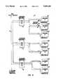
- FIG. 5is a block diagram of a power distribution system wherein various subscribers coupled to a common primary line and transceivers at each subscriber site are shown.
- FIG. 1shows a power line carrier communications system 10 where electrical power is distributed from an electrical utility generating plant (not shown), along primary power lines 12, to utility subscribers A, B, C, and D.
- Three distribution transformers 14, 16, 18are shown.
- Each distribution transformerhas a primary winding, such as winding 20, 22, or 24, coupled to primary power lines 12, and each primary winding is magnetically coupled, and provides power, to a secondary winding, such as winding 26, 28, or 30.
- Subscriber power lines at subscriber sitesare coupled to the secondary winding of one of the distribution transformers.
- a single distribution transformermay supply more than one subscriber, such as distribution transformer 18, which supplies power to subscriber C and subscriber D.
- exemplary subscriber site AElectrical power is conveyed to exemplary subscriber site A, through secondary power lines 32a. Power is also conveyed to other subscribers through other secondary power lines 32b-d.
- one distribution transformerprovides power for more than one or two subscribers. However for clarity, only a sample of subscribers is illustrated in the figures.
- transceiver 34ais coupled to secondary power lines 32a through coupling capacitors 36 and 38.
- Other transceivers 34b-dare similarly coupled to respective secondary power lines at subscriber sites through similar coupling capacitors.
- the coupling capacitorsare selected to block the power at the power line frequency of 60 Hz from reaching the transceivers, but not to block a communication signal at a higher carrier frequency.
- datais modulated onto a 230 kHz carrier signal, and coupling capacitors 36, 38 each have a capacitance sufficient to convey the carrier with an impedance substantially less than power frequency signals, typically in the small microfarad range.
- the carrier frequencyranges from 10 kHz to 400 kHz.
- the coupling capacitorsmay be selected to establish a high-pass filter circuit with the ambient inductance of the system.
- a communication path at the carrier frequency between two subscribers, such as A and Bis modelled by the circuit shown in FIG. 2.
- signalsare placed on the transformer secondary leads as common-mode signals, and because of the impedance of the distribution transformer's primary-to-secondary capacitance at the carrier frequency, the path from subscriber A to subscriber B is a low attenuation path compared with differential coupling.
- a PLC signal relative to earth groundis transmitted from transceiver 34a through coupling capacitors 36, 38, secondary-to-primary winding capacitances 70, 72 of distribution transformer 14, primary distribution lines 12, primary-to-secondary winding capacitances 74, 76 of distribution transformer 16, and coupling capacitors 40, 42, to transceiver 34b, where the signal provided to transceiver 34b on line 78 is referenced to earth ground.
- FIG. 2communication is possible in the other direction, from transceiver 34b to transceiver 34a, as well as communication in both directions simultaneously. It should be further apparent that communication is also possible using only one of the two parallel paths shown in FIG. 2. However an embodiment using parallel paths is the preferred embodiment.
- FIG. 3is a schematic diagram of a power line carrier communication system 80, which is similar to that shown in FIG. 1 except the secondary power lines carry three-phase power on four lines, and the distribution transformers are configured on in a wye configuration.
- the distribution transformersare configured on in a wye configuration.
- FIG. 3only two subscriber sites are shown. However, in a typical power distribution system, several sites are powered from one transformer, and more than two transformers receive power from a primary distribution line.
- Three-phase electrical poweris provided to subscriber A from primary distribution line 82 through the primary windings of distribution transformer 84, the secondary windings of distribution transformer 84, and secondary distribution lines 88. Electrical power is provided to subscriber B through distribution transformer 86 and secondary distribution lines 90.
- Transceiver 94transmits a PLC signal to transceiver 100.
- Transceiver 100also may transmit a signal to transceiver 94. However, only transmission in one direction will be described here.
- a signal output from transceiver 94is applied equally to three coupling capacitors 92a-c. These coupling capacitors couple the high-frequency signal (10 kHz-400 kHz) onto each line of secondary distribution lines 88 while preventing the high power at the power line frequency (60 Hz or lower) from reaching transceiver 94.
- the PLC signalis a common-mode signal relative to earth ground, and the center node of the secondary windings of distribution transformer 84 is coupled to earth ground, the PLC signal is imposed on the three secondary windings. Due to capacitive coupling, and some magnetic coupling in this case, the signal is transmitted through to the primary side of distribution transformer 84. In a similar manner, the signal is transmitted through primary distribution lines 82, distribution transformer 86 and a second set of coupling capacitors 98a-c, to reach transceiver 100.
- FIG. 4is a schematic diagram of a power line carrier communication system 80'. It is similar to communication system 80, except that the distribution transformers are configured as a closed delta. Enumeration of elements is as in FIG. 3.
- FIG. 5is a block diagram of a communication system 110 in accordance with the present invention, illustrating the transmission of data packets from one site to another.
- Data originating at a subscriber site 120is packaged into a packet, such as packet 118, where packet 118 includes information indicating a destination address.
- Datais transmitted through the power system as shown in FIGS. 1, 3, or 4, and is transmitted as digital modulation of a carrier signal, as is well known in the art.
- the packetis transmitted to more than one transceiver by virtue of the fact that many transceivers are coupled to power distribution lines which can carry signals from the originating transceiver.
- each transceivercontains hardware or software for reading the address data in each received packet, and rejects those packets which do not have an address matching the assigned address of the transceiver.
- packet 118is transmitted to all transceivers, but only the addressee, namely, transceiver 3A, accepts and processes the packet.
- packet 118is retrieved by transceiver 2B and retransmitted to its final destination, transceiver 3A.
- transceiver 3ASuch an embodiment is useful where a packet may need to be transferred further than line noise and attenuation would otherwise allow.
- each of the transceivershas such a store-and-forward capability, and in other embodiments, only selected transceivers may store and forward packets.
- the packetscan be easily encoded according to an error-correcting code, and error-detecting and correcting protocols can be used as is known to conventional packet communication systems.
- the distance from a transceiver to a subscriber siteis not limited in the present invention, although in many cases a transceiver will operate in conjunction with a power meter to record the amount of power used at the subscriber site or used to disable the flow of power to the site. Not all transceivers need be located near a subscriber site, however. For example, some transceivers might be used to collect data from power meter transceivers and to transmit the collected data via radio or other non-PLC communication means, to a central utility computer. Such a transceiver might be located high on a power pole to efficiently communicate using radio signals, or near telephone lines to easily couple to telephone lines.
- a transceiver on a power distribution transformercan broadcast data to a plurality of transceivers on a plurality of other power distribution transformers; two-way communication can be broadcast from transceivers on different power distribution transformers; or communication can occur between sites separated by more than one level of distribution, in which case signals will travel up and down several levels of distribution transformers.
- the scope of the inventionshould, therefore, be determined not with reference to the above description, but instead should be determined with reference to the appended claims along with their full scope of equivalents.
Landscapes
- Engineering & Computer Science (AREA)
- Power Engineering (AREA)
- Computer Networks & Wireless Communication (AREA)
- Signal Processing (AREA)
- Cable Transmission Systems, Equalization Of Radio And Reduction Of Echo (AREA)
Abstract
Description
Claims (8)
Priority Applications (2)
| Application Number | Priority Date | Filing Date | Title |
|---|---|---|---|
| US08/028,487US5406249A (en) | 1993-03-09 | 1993-03-09 | Method and structure for coupling power-line carrier current signals using common-mode coupling |
| PCT/US1994/002202WO1994021076A1 (en) | 1993-03-09 | 1994-03-03 | Method and structure for coupling power-line carrier current signals using common-mode coupling |
Applications Claiming Priority (1)
| Application Number | Priority Date | Filing Date | Title |
|---|---|---|---|
| US08/028,487US5406249A (en) | 1993-03-09 | 1993-03-09 | Method and structure for coupling power-line carrier current signals using common-mode coupling |
Publications (1)
| Publication Number | Publication Date |
|---|---|
| US5406249Atrue US5406249A (en) | 1995-04-11 |
Family
ID=21843716
Family Applications (1)
| Application Number | Title | Priority Date | Filing Date |
|---|---|---|---|
| US08/028,487Expired - LifetimeUS5406249A (en) | 1993-03-09 | 1993-03-09 | Method and structure for coupling power-line carrier current signals using common-mode coupling |
Country Status (2)
| Country | Link |
|---|---|
| US (1) | US5406249A (en) |
| WO (1) | WO1994021076A1 (en) |
Cited By (74)
| Publication number | Priority date | Publication date | Assignee | Title |
|---|---|---|---|---|
| US5481478A (en)* | 1994-06-03 | 1996-01-02 | Palmieri; Herman D. | Broadcast system for a facility |
| US5553081A (en)* | 1994-04-08 | 1996-09-03 | Echelon Corporation | Apparatus and method for detecting a signal in a communications system |
| US5796604A (en)* | 1994-04-22 | 1998-08-18 | Sgs-Thomson Microelectronics, S.A. | System comprising a machine for the communication of pricing changes |
| US5818821A (en) | 1994-12-30 | 1998-10-06 | Intelogis, Inc. | Universal lan power line carrier repeater system and method |
| US5929750A (en)* | 1992-10-22 | 1999-07-27 | Norweb Plc | Transmission network and filter therefor |
| US5949327A (en)* | 1994-08-26 | 1999-09-07 | Norweb Plc | Coupling of telecommunications signals to a balanced power distribution network |
| US5970127A (en) | 1997-10-16 | 1999-10-19 | Phonex Corporation | Caller identification system for wireless phone jacks and wireless modem jacks |
| US5986574A (en)* | 1997-10-16 | 1999-11-16 | Peco Energy Company | System and method for communication between remote locations |
| US6037857A (en)* | 1997-06-06 | 2000-03-14 | Allen-Bradley Company, Llc | Serial data isolator industrial control system providing intrinsically safe operation |
| US6055435A (en) | 1997-10-16 | 2000-04-25 | Phonex Corporation | Wireless telephone connection surge suppressor |
| US6107912A (en) | 1997-12-08 | 2000-08-22 | Phonex Corporation | Wireless modem jack |
| US6144292A (en)* | 1992-10-22 | 2000-11-07 | Norweb Plc | Powerline communications network employing TDMA, FDMA and/or CDMA |
| US6243571B1 (en) | 1998-09-21 | 2001-06-05 | Phonex Corporation | Method and system for distribution of wireless signals for increased wireless coverage using power lines |
| US6246868B1 (en) | 1998-08-14 | 2001-06-12 | Phonex Corporation | Conversion and distribution of incoming wireless telephone signals using the power line |
| US6255935B1 (en)* | 1998-09-14 | 2001-07-03 | Abb Research Ltd. | Coupling capacitor having an integrated connecting cable |
| US6282405B1 (en) | 1992-10-22 | 2001-08-28 | Norweb Plc | Hybrid electricity and telecommunications distribution network |
| US20010054953A1 (en)* | 2000-04-14 | 2001-12-27 | Kline Paul A. | Digital communications utilizing medium voltage power distribution lines |
| WO2002054605A1 (en)* | 2000-12-28 | 2002-07-11 | Ambient Corporation | Inductive coupling of a data signal to a power transmission cable |
| US20020097953A1 (en)* | 2000-12-15 | 2002-07-25 | Kline Paul A. | Interfacing fiber optic data with electrical power systems |
| US20020120569A1 (en)* | 1997-10-16 | 2002-08-29 | Day Mark E. | System and method for communication between remote locations |
| US20020118101A1 (en)* | 2001-02-14 | 2002-08-29 | Kline Paul A. | Data communication over a power line |
| US6507573B1 (en)* | 1997-03-27 | 2003-01-14 | Frank Brandt | Data transfer method and system in low voltage networks |
| US6549120B1 (en) | 2000-11-24 | 2003-04-15 | Kinectrics Inc. | Device for sending and receiving data through power distribution transformers |
| WO2003044982A1 (en)* | 2001-11-21 | 2003-05-30 | Schneider Electric Powerline Communications Ab | Coupler arrangement |
| US20030151491A1 (en)* | 2000-04-19 | 2003-08-14 | Fabrice Martin | Method and device for monitoring enablement of an electrical apparatus connected to a power grid |
| US20030169155A1 (en)* | 2000-04-14 | 2003-09-11 | Mollenkopf James Douglas | Power line communication system and method of using the same |
| US20030179080A1 (en)* | 2001-12-21 | 2003-09-25 | Mollenkopf James Douglas | Facilitating communication of data signals on electric power systems |
| US20030190110A1 (en)* | 2001-02-14 | 2003-10-09 | Kline Paul A. | Method and apparatus for providing inductive coupling and decoupling of high-frequency, high-bandwidth data signals directly on and off of a high voltage power line |
| US20030201873A1 (en)* | 2002-04-29 | 2003-10-30 | Ambient Corporation | High current inductive coupler and current transformer for power lines |
| US20030234713A1 (en)* | 2002-06-21 | 2003-12-25 | Pridmore Charles Franklin | Power line coupling device and method of using the same |
| US20040048613A1 (en)* | 2002-08-14 | 2004-03-11 | Kataname, Inc. | System for mobile broadband networking using dynamic quality of service provisioning |
| US20040110483A1 (en)* | 2002-12-10 | 2004-06-10 | Mollenkopf James Douglas | Power line communication sytem and method |
| US20040113756A1 (en)* | 2002-12-10 | 2004-06-17 | Mollenkopf James Douglas | Device and method for coupling with electrical distribution network infrastructure to provide communications |
| US20040113757A1 (en)* | 2002-12-10 | 2004-06-17 | White Melvin Joseph | Power line communication system and method of operating the same |
| US20040135676A1 (en)* | 2002-12-10 | 2004-07-15 | Berkman William H. | Power line communication system and method of operating the same |
| US20040142599A1 (en)* | 2003-01-21 | 2004-07-22 | Cope Leonard D. | Power line coupling device and method of using the same |
| US6809633B2 (en) | 2001-03-29 | 2004-10-26 | Ambient Corporation | Coupling broadband modems to power lines |
| US20040227622A1 (en)* | 2003-05-13 | 2004-11-18 | Giannini Paul M. | Device and method for communicating data signals through multiple power line conductors |
| US20040227621A1 (en)* | 2000-04-14 | 2004-11-18 | Cope Leonard D. | Power line communication apparatus and method of using the same |
| US20040227623A1 (en)* | 2003-05-07 | 2004-11-18 | Telkonet, Inc. | Network topology and packet routing method using low voltage power wiring |
| US20040233928A1 (en)* | 2003-05-07 | 2004-11-25 | Telkonet, Inc. | Network topology and packet routing method using low voltage power wiring |
| US20050046550A1 (en)* | 2001-10-02 | 2005-03-03 | Crenshaw Ralph E. | Method and apparatus for attaching power line communications to customer premises |
| US20050062589A1 (en)* | 1999-12-30 | 2005-03-24 | Ambient Corporation | Arrangement of inductive couplers for data communication |
| US20050248441A1 (en)* | 2001-10-02 | 2005-11-10 | Telkonet Communications, Inc. | Method and apparatus for attaching power line communications to customer premises |
| US6977578B2 (en) | 2000-01-20 | 2005-12-20 | Current Technologies, Llc | Method of isolating data in a power line communications network |
| US6980089B1 (en) | 2000-08-09 | 2005-12-27 | Current Technologies, Llc | Non-intrusive coupling to shielded power cable |
| US6982611B2 (en) | 2002-06-24 | 2006-01-03 | Current Technologies, Llc | Power line coupling device and method of using the same |
| US7015809B1 (en) | 2002-08-14 | 2006-03-21 | Skipper Wireless Inc. | Method and system for providing an active routing antenna |
| US20060071853A1 (en)* | 2002-08-14 | 2006-04-06 | Kataname, Inc. | Method and system for determining direction of transmission using multi-facet antenna |
| US20060087382A1 (en)* | 2004-10-25 | 2006-04-27 | Ambient Corporation | Inductive coupler for power line communications |
| US7076378B1 (en) | 2002-11-13 | 2006-07-11 | Current Technologies, Llc | Device and method for providing power line characteristics and diagnostics |
| US20060187015A1 (en)* | 2005-02-18 | 2006-08-24 | Gaptek, Inc. | Method and apparatus for communicating control and other information over a power bus |
| US20060193336A1 (en)* | 2005-02-25 | 2006-08-31 | Telkonet, Inc. | Local area network above cable television methods and devices |
| US20060193310A1 (en)* | 2005-02-25 | 2006-08-31 | Telkonet, Inc. | Local area network above telephony methods and devices |
| US20060193313A1 (en)* | 2005-02-25 | 2006-08-31 | Telkonet, Inc. | Local area network above telephony infrastructure |
| US7113134B1 (en) | 2004-03-12 | 2006-09-26 | Current Technologies, Llc | Transformer antenna device and method of using the same |
| US7132819B1 (en) | 2002-11-12 | 2006-11-07 | Current Technologies, Llc | Floating power supply and method of using the same |
| US20070025353A1 (en)* | 2005-07-14 | 2007-02-01 | Skipper Wireless, Inc. | Method and system for providing location-based addressing |
| US7199699B1 (en) | 2002-02-19 | 2007-04-03 | Current Technologies, Llc | Facilitating communication with power line communication devices |
| AU2006202255B2 (en)* | 2000-12-28 | 2007-05-24 | Ambient Corporation | Inductive coupling of a data signal to a power transmission cable |
| US20070147413A1 (en)* | 1998-07-28 | 2007-06-28 | Israeli Company Of Serconet Ltd. | Local area network of serial intelligent cells |
| US7308103B2 (en) | 2003-05-08 | 2007-12-11 | Current Technologies, Llc | Power line communication device and method of using the same |
| US20080062898A1 (en)* | 1997-09-23 | 2008-03-13 | Hunt Technologies, Inc. | Low frequency bilateral communication over distributed power lines |
| USRE40492E1 (en) | 2000-02-10 | 2008-09-09 | Telkonet Communications, Inc. | Power line telephony exchange |
| US7460467B1 (en) | 2003-07-23 | 2008-12-02 | Current Technologies, Llc | Voice-over-IP network test device and method |
| US20090315700A1 (en)* | 2006-07-25 | 2009-12-24 | Jonathan Ephriam David Hurwitz | Dual Transformer Communication Interface |
| US7656904B2 (en) | 2003-03-13 | 2010-02-02 | Mosaid Technologies Incorporated | Telephone system having multiple distinct sources and accessories therefor |
| US7778149B1 (en) | 2006-07-27 | 2010-08-17 | Tadaaki Chigusa | Method and system to providing fast access channel |
| US20100254363A1 (en)* | 2000-04-19 | 2010-10-07 | Mosaid Technologies Incorporated | Network combining wired and non-wired segments |
| US8160096B1 (en) | 2006-12-06 | 2012-04-17 | Tadaaki Chigusa | Method and system for reserving bandwidth in time-division multiplexed networks |
| US8582598B2 (en) | 1999-07-07 | 2013-11-12 | Mosaid Technologies Incorporated | Local area network for distributing data communication, sensing and control signals |
| US9559685B1 (en)* | 2014-07-11 | 2017-01-31 | Silego Technology, Inc. | Power and data switch |
| US20190128936A1 (en)* | 2017-11-01 | 2019-05-02 | Sun Digital Systems Inc | Impedance isolated power and wired data communication network |
| US12074565B2 (en) | 2014-10-28 | 2024-08-27 | Solaredge Technologies Ltd. | Photovoltaic module or array shutdown |
Families Citing this family (2)
| Publication number | Priority date | Publication date | Assignee | Title |
|---|---|---|---|---|
| US5896382A (en)* | 1996-11-19 | 1999-04-20 | Scientific-Atlanta, Inc. | Method and apparatus for communicating information between a headend and subscriber over a wide area network |
| DE102007046980A1 (en)* | 2007-09-28 | 2009-05-14 | Siemens Ag | Electrical consumer i.e. electric motor, has modulation circuit galvanically connected with earth and comprising modulation unit for modulation of current discharged over capacitive connection |
Citations (21)
| Publication number | Priority date | Publication date | Assignee | Title |
|---|---|---|---|---|
| US3075129A (en)* | 1960-04-06 | 1963-01-22 | Dallemagne Robert | Coded signal receiving and shaping circuit |
| US3846638A (en)* | 1972-10-02 | 1974-11-05 | Gen Electric | Improved coupling arrangement for power line carrier systems |
| US3942170A (en)* | 1975-01-31 | 1976-03-02 | Westinghouse Electric Corporation | Distribution network powerline carrier communication system |
| US4008467A (en)* | 1975-09-16 | 1977-02-15 | Westinghouse Electric Corporation | Power line carrier communication system having efficient carrier signal coupling of distribution secondary lines |
| US4066912A (en)* | 1976-04-21 | 1978-01-03 | General Electric Company | Coupling arrangement for power line carrier systems |
| US4357598A (en)* | 1981-04-09 | 1982-11-02 | Westinghouse Electric Corp. | Three-phase power distribution network communication system |
| US4427968A (en)* | 1981-04-09 | 1984-01-24 | Westinghouse Electric Corp. | Distribution network communication system with flexible message routes |
| US4473817A (en)* | 1982-04-13 | 1984-09-25 | Rockwell International Corporation | Coupling power line communications signals around distribution transformers |
| US4481501A (en)* | 1978-08-17 | 1984-11-06 | Rockwell International Corporation | Transformer arrangement for coupling a communication signal to a three-phase power line |
| US4556864A (en)* | 1982-08-26 | 1985-12-03 | Roy Joseph J | Apparatus and method for communicating digital information on AC power lines |
| US4714912A (en)* | 1986-12-31 | 1987-12-22 | General Electric Company | Single-conductor power line communications system |
| US4745391A (en)* | 1987-02-26 | 1988-05-17 | General Electric Company | Method of, and apparatus for, information communication via a power line conductor |
| US4766414A (en)* | 1986-06-17 | 1988-08-23 | Westinghouse Electric Corp. | Power line communication interference preventing circuit |
| US4772870A (en)* | 1986-11-20 | 1988-09-20 | Reyes Ronald R | Power line communication system |
| US4806929A (en)* | 1986-03-31 | 1989-02-21 | Hitachi, Ltd. | Remote monitor control system |
| US4890089A (en)* | 1988-11-25 | 1989-12-26 | Westinghouse Electric Corp. | Distribution of line carrier communications |
| US4903006A (en)* | 1989-02-16 | 1990-02-20 | Thermo King Corporation | Power line communication system |
| US4935837A (en)* | 1989-04-03 | 1990-06-19 | Abb Power T&D Company Inc. | Phase comparison relaying system with single channel communications link |
| US4962496A (en)* | 1988-10-20 | 1990-10-09 | Abb Power T & D Company Inc. | Transmission of data via power lines |
| US5066939A (en)* | 1989-10-04 | 1991-11-19 | Mansfield Jr Amos R | Method and means of operating a power line carrier communication system |
| US5210519A (en)* | 1990-06-22 | 1993-05-11 | British Aerospace Public Limited Company | Digital data transmission |
Family Cites Families (1)
| Publication number | Priority date | Publication date | Assignee | Title |
|---|---|---|---|---|
| US4473317A (en)* | 1981-06-22 | 1984-09-25 | The Boeing Company | Anti-backlash mechanism for a spline connection |
- 1993
- 1993-03-09USUS08/028,487patent/US5406249A/ennot_activeExpired - Lifetime
- 1994
- 1994-03-03WOPCT/US1994/002202patent/WO1994021076A1/enactiveApplication Filing
Patent Citations (21)
| Publication number | Priority date | Publication date | Assignee | Title |
|---|---|---|---|---|
| US3075129A (en)* | 1960-04-06 | 1963-01-22 | Dallemagne Robert | Coded signal receiving and shaping circuit |
| US3846638A (en)* | 1972-10-02 | 1974-11-05 | Gen Electric | Improved coupling arrangement for power line carrier systems |
| US3942170A (en)* | 1975-01-31 | 1976-03-02 | Westinghouse Electric Corporation | Distribution network powerline carrier communication system |
| US4008467A (en)* | 1975-09-16 | 1977-02-15 | Westinghouse Electric Corporation | Power line carrier communication system having efficient carrier signal coupling of distribution secondary lines |
| US4066912A (en)* | 1976-04-21 | 1978-01-03 | General Electric Company | Coupling arrangement for power line carrier systems |
| US4481501A (en)* | 1978-08-17 | 1984-11-06 | Rockwell International Corporation | Transformer arrangement for coupling a communication signal to a three-phase power line |
| US4427968A (en)* | 1981-04-09 | 1984-01-24 | Westinghouse Electric Corp. | Distribution network communication system with flexible message routes |
| US4357598A (en)* | 1981-04-09 | 1982-11-02 | Westinghouse Electric Corp. | Three-phase power distribution network communication system |
| US4473817A (en)* | 1982-04-13 | 1984-09-25 | Rockwell International Corporation | Coupling power line communications signals around distribution transformers |
| US4556864A (en)* | 1982-08-26 | 1985-12-03 | Roy Joseph J | Apparatus and method for communicating digital information on AC power lines |
| US4806929A (en)* | 1986-03-31 | 1989-02-21 | Hitachi, Ltd. | Remote monitor control system |
| US4766414A (en)* | 1986-06-17 | 1988-08-23 | Westinghouse Electric Corp. | Power line communication interference preventing circuit |
| US4772870A (en)* | 1986-11-20 | 1988-09-20 | Reyes Ronald R | Power line communication system |
| US4714912A (en)* | 1986-12-31 | 1987-12-22 | General Electric Company | Single-conductor power line communications system |
| US4745391A (en)* | 1987-02-26 | 1988-05-17 | General Electric Company | Method of, and apparatus for, information communication via a power line conductor |
| US4962496A (en)* | 1988-10-20 | 1990-10-09 | Abb Power T & D Company Inc. | Transmission of data via power lines |
| US4890089A (en)* | 1988-11-25 | 1989-12-26 | Westinghouse Electric Corp. | Distribution of line carrier communications |
| US4903006A (en)* | 1989-02-16 | 1990-02-20 | Thermo King Corporation | Power line communication system |
| US4935837A (en)* | 1989-04-03 | 1990-06-19 | Abb Power T&D Company Inc. | Phase comparison relaying system with single channel communications link |
| US5066939A (en)* | 1989-10-04 | 1991-11-19 | Mansfield Jr Amos R | Method and means of operating a power line carrier communication system |
| US5210519A (en)* | 1990-06-22 | 1993-05-11 | British Aerospace Public Limited Company | Digital data transmission |
Non-Patent Citations (3)
| Title |
|---|
| ABB Power T&D Company Inc., EMETCON Automated Distribution System Brochure (Jan. 1990).* |
| Armando Garcia, Florida Power & Light, Notes from National Symposium on Automatic Meter Reading (Sep. 1989).* |
| Westinghouse ABB Power T&D Company, EMETCON Automated Distribution System Communication Guide (Sep. 1989).* |
Cited By (145)
| Publication number | Priority date | Publication date | Assignee | Title |
|---|---|---|---|---|
| US6144292A (en)* | 1992-10-22 | 2000-11-07 | Norweb Plc | Powerline communications network employing TDMA, FDMA and/or CDMA |
| US6282405B1 (en) | 1992-10-22 | 2001-08-28 | Norweb Plc | Hybrid electricity and telecommunications distribution network |
| US5929750A (en)* | 1992-10-22 | 1999-07-27 | Norweb Plc | Transmission network and filter therefor |
| US5933071A (en)* | 1992-10-22 | 1999-08-03 | Norweb Plc | Electricity distribution and/or power transmission network and filter for telecommunication over power lines |
| US6172597B1 (en) | 1992-10-22 | 2001-01-09 | Norweb Plc | Electricity distribution and/or power transmission network and filter for telecommunication over power lines |
| US5553081A (en)* | 1994-04-08 | 1996-09-03 | Echelon Corporation | Apparatus and method for detecting a signal in a communications system |
| US5796604A (en)* | 1994-04-22 | 1998-08-18 | Sgs-Thomson Microelectronics, S.A. | System comprising a machine for the communication of pricing changes |
| US5481478A (en)* | 1994-06-03 | 1996-01-02 | Palmieri; Herman D. | Broadcast system for a facility |
| US5949327A (en)* | 1994-08-26 | 1999-09-07 | Norweb Plc | Coupling of telecommunications signals to a balanced power distribution network |
| US5818821A (en) | 1994-12-30 | 1998-10-06 | Intelogis, Inc. | Universal lan power line carrier repeater system and method |
| US6507573B1 (en)* | 1997-03-27 | 2003-01-14 | Frank Brandt | Data transfer method and system in low voltage networks |
| US6037857A (en)* | 1997-06-06 | 2000-03-14 | Allen-Bradley Company, Llc | Serial data isolator industrial control system providing intrinsically safe operation |
| US20080062898A1 (en)* | 1997-09-23 | 2008-03-13 | Hunt Technologies, Inc. | Low frequency bilateral communication over distributed power lines |
| US20090296832A1 (en)* | 1997-09-23 | 2009-12-03 | Hunt Technologies, Inc. | Low Frequency Bilateral Communication Over Distributed Power Lines |
| US6055435A (en) | 1997-10-16 | 2000-04-25 | Phonex Corporation | Wireless telephone connection surge suppressor |
| US20020120569A1 (en)* | 1997-10-16 | 2002-08-29 | Day Mark E. | System and method for communication between remote locations |
| US5970127A (en) | 1997-10-16 | 1999-10-19 | Phonex Corporation | Caller identification system for wireless phone jacks and wireless modem jacks |
| US5986574A (en)* | 1997-10-16 | 1999-11-16 | Peco Energy Company | System and method for communication between remote locations |
| US6107912A (en) | 1997-12-08 | 2000-08-22 | Phonex Corporation | Wireless modem jack |
| US20070195719A1 (en)* | 1998-07-28 | 2007-08-23 | Serconet, Ltd. | Local area network of serial intelligent cells |
| US7978726B2 (en) | 1998-07-28 | 2011-07-12 | Mosaid Technologies Incorporated | Local area network of serial intelligent cells |
| US8867523B2 (en) | 1998-07-28 | 2014-10-21 | Conversant Intellectual Property Management Incorporated | Local area network of serial intelligent cells |
| US8325636B2 (en) | 1998-07-28 | 2012-12-04 | Mosaid Technologies Incorporated | Local area network of serial intelligent cells |
| US20070147413A1 (en)* | 1998-07-28 | 2007-06-28 | Israeli Company Of Serconet Ltd. | Local area network of serial intelligent cells |
| US8885659B2 (en) | 1998-07-28 | 2014-11-11 | Conversant Intellectual Property Management Incorporated | Local area network of serial intelligent cells |
| US8885660B2 (en) | 1998-07-28 | 2014-11-11 | Conversant Intellectual Property Management Incorporated | Local area network of serial intelligent cells |
| US7424031B2 (en) | 1998-07-28 | 2008-09-09 | Serconet, Ltd. | Local area network of serial intelligent cells |
| US8908673B2 (en) | 1998-07-28 | 2014-12-09 | Conversant Intellectual Property Management Incorporated | Local area network of serial intelligent cells |
| US8270430B2 (en) | 1998-07-28 | 2012-09-18 | Mosaid Technologies Incorporated | Local area network of serial intelligent cells |
| US20070183447A1 (en)* | 1998-07-28 | 2007-08-09 | Israeli Company Of Serconet Ltd. | Local area network of serial intelligent cells |
| US7852874B2 (en) | 1998-07-28 | 2010-12-14 | Mosaid Technologies Incorporated | Local area network of serial intelligent cells |
| US6246868B1 (en) | 1998-08-14 | 2001-06-12 | Phonex Corporation | Conversion and distribution of incoming wireless telephone signals using the power line |
| US6255935B1 (en)* | 1998-09-14 | 2001-07-03 | Abb Research Ltd. | Coupling capacitor having an integrated connecting cable |
| US6243571B1 (en) | 1998-09-21 | 2001-06-05 | Phonex Corporation | Method and system for distribution of wireless signals for increased wireless coverage using power lines |
| US8582598B2 (en) | 1999-07-07 | 2013-11-12 | Mosaid Technologies Incorporated | Local area network for distributing data communication, sensing and control signals |
| US6646447B2 (en) | 1999-12-30 | 2003-11-11 | Ambient Corporation | Identifying one of a plurality of wires of a power transmission cable |
| US20030160684A1 (en)* | 1999-12-30 | 2003-08-28 | Ambient Corporation | Inductive coupling of a data signal for a power transmission cable |
| US6452482B1 (en)* | 1999-12-30 | 2002-09-17 | Ambient Corporation | Inductive coupling of a data signal to a power transmission cable |
| US7154382B2 (en) | 1999-12-30 | 2006-12-26 | Ambient Corporation | Arrangement of inductive couplers for data communication |
| US6897764B2 (en) | 1999-12-30 | 2005-05-24 | Ambient Corporation | Inductive coupling of a data signal for a power transmission cable |
| US20050062589A1 (en)* | 1999-12-30 | 2005-03-24 | Ambient Corporation | Arrangement of inductive couplers for data communication |
| US6977578B2 (en) | 2000-01-20 | 2005-12-20 | Current Technologies, Llc | Method of isolating data in a power line communications network |
| USRE40492E1 (en) | 2000-02-10 | 2008-09-09 | Telkonet Communications, Inc. | Power line telephony exchange |
| US20040227621A1 (en)* | 2000-04-14 | 2004-11-18 | Cope Leonard D. | Power line communication apparatus and method of using the same |
| US6958680B2 (en) | 2000-04-14 | 2005-10-25 | Current Technologies, Llc | Power line communication system and method of using the same |
| US6998962B2 (en) | 2000-04-14 | 2006-02-14 | Current Technologies, Llc | Power line communication apparatus and method of using the same |
| US20010054953A1 (en)* | 2000-04-14 | 2001-12-27 | Kline Paul A. | Digital communications utilizing medium voltage power distribution lines |
| US7307511B2 (en) | 2000-04-14 | 2007-12-11 | Current Technologies, Llc | Power line communication system and method |
| US7245212B2 (en) | 2000-04-14 | 2007-07-17 | Current Technologies, Llc | Power line communication apparatus and method of using the same |
| US20030169155A1 (en)* | 2000-04-14 | 2003-09-11 | Mollenkopf James Douglas | Power line communication system and method of using the same |
| US20050206507A1 (en)* | 2000-04-14 | 2005-09-22 | Kline Paul A | Power line communication system and method |
| US6965302B2 (en) | 2000-04-14 | 2005-11-15 | Current Technologies, Llc | Power line communication system and method of using the same |
| US8873586B2 (en) | 2000-04-19 | 2014-10-28 | Conversant Intellectual Property Management Incorporated | Network combining wired and non-wired segments |
| US7876767B2 (en) | 2000-04-19 | 2011-01-25 | Mosaid Technologies Incorporated | Network combining wired and non-wired segments |
| US20030151491A1 (en)* | 2000-04-19 | 2003-08-14 | Fabrice Martin | Method and device for monitoring enablement of an electrical apparatus connected to a power grid |
| US6950007B2 (en)* | 2000-04-19 | 2005-09-27 | Electricite De France Service National | Method and device for monitoring enablement of an electrical apparatus connected to a power grid |
| US20100254363A1 (en)* | 2000-04-19 | 2010-10-07 | Mosaid Technologies Incorporated | Network combining wired and non-wired segments |
| US8867506B2 (en) | 2000-04-19 | 2014-10-21 | Conversant Intellectual Property Management Incorporated | Network combining wired and non-wired segments |
| US8873575B2 (en) | 2000-04-19 | 2014-10-28 | Conversant Intellectual Property Management Incorporated | Network combining wired and non-wired segments |
| US8289991B2 (en) | 2000-04-19 | 2012-10-16 | Mosaid Technologies Incorporated | Network combining wired and non-wired segments |
| US8982904B2 (en) | 2000-04-19 | 2015-03-17 | Conversant Intellectual Property Management Inc. | Network combining wired and non-wired segments |
| US20100254362A1 (en)* | 2000-04-19 | 2010-10-07 | Mosaid Technologies Incorporated | Network combining wired and non-wired segments |
| US8982903B2 (en) | 2000-04-19 | 2015-03-17 | Conversant Intellectual Property Management Inc. | Network combining wired and non-wired segments |
| US8848725B2 (en) | 2000-04-19 | 2014-09-30 | Conversant Intellectual Property Management Incorporated | Network combining wired and non-wired segments |
| US7933297B2 (en) | 2000-04-19 | 2011-04-26 | Mosaid Technologies Incorporated | Network combining wired and non-wired segments |
| US6980089B1 (en) | 2000-08-09 | 2005-12-27 | Current Technologies, Llc | Non-intrusive coupling to shielded power cable |
| US6549120B1 (en) | 2000-11-24 | 2003-04-15 | Kinectrics Inc. | Device for sending and receiving data through power distribution transformers |
| US20020097953A1 (en)* | 2000-12-15 | 2002-07-25 | Kline Paul A. | Interfacing fiber optic data with electrical power systems |
| AU2006202255B2 (en)* | 2000-12-28 | 2007-05-24 | Ambient Corporation | Inductive coupling of a data signal to a power transmission cable |
| WO2002054605A1 (en)* | 2000-12-28 | 2002-07-11 | Ambient Corporation | Inductive coupling of a data signal to a power transmission cable |
| KR100755145B1 (en)* | 2000-12-28 | 2007-09-04 | 앰비언트 코오퍼레이션 | Data signal inductive coupling to power transmission cable |
| US20030190110A1 (en)* | 2001-02-14 | 2003-10-09 | Kline Paul A. | Method and apparatus for providing inductive coupling and decoupling of high-frequency, high-bandwidth data signals directly on and off of a high voltage power line |
| US20070287406A1 (en)* | 2001-02-14 | 2007-12-13 | Kline Paul A | Data Communication over a Power Line |
| US7453352B2 (en) | 2001-02-14 | 2008-11-18 | Current Technologies, Llc | Data communication over a power line |
| US7218219B2 (en) | 2001-02-14 | 2007-05-15 | Current Technologies, Llc | Data communication over a power line |
| US6933835B2 (en) | 2001-02-14 | 2005-08-23 | Current Technologies, Llc | Data communication over a power line |
| US20060171174A1 (en)* | 2001-02-14 | 2006-08-03 | Kline Paul A | Data communication over a power line |
| US6950567B2 (en) | 2001-02-14 | 2005-09-27 | Current Technologies, Llc | Method and apparatus for providing inductive coupling and decoupling of high-frequency, high-bandwidth data signals directly on and off of a high voltage power line |
| US7414518B2 (en) | 2001-02-14 | 2008-08-19 | Current Technologies, Llc | Power line communication device and method |
| US7042351B2 (en) | 2001-02-14 | 2006-05-09 | Current Technologies, Llc | Data communication over a power line |
| US20020118101A1 (en)* | 2001-02-14 | 2002-08-29 | Kline Paul A. | Data communication over a power line |
| US7103240B2 (en) | 2001-02-14 | 2006-09-05 | Current Technologies, Llc | Method and apparatus for providing inductive coupling and decoupling of high-frequency, high-bandwidth data signals directly on and off of a high voltage power line |
| US6809633B2 (en) | 2001-03-29 | 2004-10-26 | Ambient Corporation | Coupling broadband modems to power lines |
| US20050253690A1 (en)* | 2001-10-02 | 2005-11-17 | Telkonet Communications, Inc. | Method and apparatus for attaching power line communications to customer premises |
| US20050248441A1 (en)* | 2001-10-02 | 2005-11-10 | Telkonet Communications, Inc. | Method and apparatus for attaching power line communications to customer premises |
| US7091831B2 (en)* | 2001-10-02 | 2006-08-15 | Telkonet Communications, Inc. | Method and apparatus for attaching power line communications to customer premises |
| US20050046550A1 (en)* | 2001-10-02 | 2005-03-03 | Crenshaw Ralph E. | Method and apparatus for attaching power line communications to customer premises |
| WO2003044982A1 (en)* | 2001-11-21 | 2003-05-30 | Schneider Electric Powerline Communications Ab | Coupler arrangement |
| US7053756B2 (en) | 2001-12-21 | 2006-05-30 | Current Technologies, Llc | Facilitating communication of data signals on electric power systems |
| US20030179080A1 (en)* | 2001-12-21 | 2003-09-25 | Mollenkopf James Douglas | Facilitating communication of data signals on electric power systems |
| US7199699B1 (en) | 2002-02-19 | 2007-04-03 | Current Technologies, Llc | Facilitating communication with power line communication devices |
| US7061370B2 (en)* | 2002-04-29 | 2006-06-13 | Ambient Corporation | High current inductive coupler and current transformer for power lines |
| US20030201873A1 (en)* | 2002-04-29 | 2003-10-30 | Ambient Corporation | High current inductive coupler and current transformer for power lines |
| US20030234713A1 (en)* | 2002-06-21 | 2003-12-25 | Pridmore Charles Franklin | Power line coupling device and method of using the same |
| US7102478B2 (en) | 2002-06-21 | 2006-09-05 | Current Technologies, Llc | Power line coupling device and method of using the same |
| US6982611B2 (en) | 2002-06-24 | 2006-01-03 | Current Technologies, Llc | Power line coupling device and method of using the same |
| US7224243B2 (en) | 2002-06-24 | 2007-05-29 | Current Technologies, Llc | Power line coupling device and method of using the same |
| US7610050B2 (en) | 2002-08-14 | 2009-10-27 | Tadaaki Chigusa | System for mobile broadband networking using dynamic quality of service provisioning |
| US7015809B1 (en) | 2002-08-14 | 2006-03-21 | Skipper Wireless Inc. | Method and system for providing an active routing antenna |
| US20060071853A1 (en)* | 2002-08-14 | 2006-04-06 | Kataname, Inc. | Method and system for determining direction of transmission using multi-facet antenna |
| US20040048613A1 (en)* | 2002-08-14 | 2004-03-11 | Kataname, Inc. | System for mobile broadband networking using dynamic quality of service provisioning |
| US20060071794A1 (en)* | 2002-08-14 | 2006-04-06 | Kataname, Inc. | Method and system for providing an active routing antenna |
| US7042394B2 (en) | 2002-08-14 | 2006-05-09 | Skipper Wireless Inc. | Method and system for determining direction of transmission using multi-facet antenna |
| US7132819B1 (en) | 2002-11-12 | 2006-11-07 | Current Technologies, Llc | Floating power supply and method of using the same |
| US7076378B1 (en) | 2002-11-13 | 2006-07-11 | Current Technologies, Llc | Device and method for providing power line characteristics and diagnostics |
| US7250848B2 (en) | 2002-12-10 | 2007-07-31 | Current Technologies, Llc | Power line communication apparatus and method of using the same |
| US6980090B2 (en) | 2002-12-10 | 2005-12-27 | Current Technologies, Llc | Device and method for coupling with electrical distribution network infrastructure to provide communications |
| US6980091B2 (en) | 2002-12-10 | 2005-12-27 | Current Technologies, Llc | Power line communication system and method of operating the same |
| US7064654B2 (en) | 2002-12-10 | 2006-06-20 | Current Technologies, Llc | Power line communication system and method of operating the same |
| US6965303B2 (en) | 2002-12-10 | 2005-11-15 | Current Technologies, Llc | Power line communication system and method |
| US20040113756A1 (en)* | 2002-12-10 | 2004-06-17 | Mollenkopf James Douglas | Device and method for coupling with electrical distribution network infrastructure to provide communications |
| US20040113757A1 (en)* | 2002-12-10 | 2004-06-17 | White Melvin Joseph | Power line communication system and method of operating the same |
| US7301440B2 (en) | 2002-12-10 | 2007-11-27 | Current Technologies, Llc | Power line communication system and method |
| US20040135676A1 (en)* | 2002-12-10 | 2004-07-15 | Berkman William H. | Power line communication system and method of operating the same |
| US7701325B2 (en) | 2002-12-10 | 2010-04-20 | Current Technologies, Llc | Power line communication apparatus and method of using the same |
| US20040110483A1 (en)* | 2002-12-10 | 2004-06-10 | Mollenkopf James Douglas | Power line communication sytem and method |
| US20040142599A1 (en)* | 2003-01-21 | 2004-07-22 | Cope Leonard D. | Power line coupling device and method of using the same |
| US7046124B2 (en) | 2003-01-21 | 2006-05-16 | Current Technologies, Llc | Power line coupling device and method of using the same |
| US7656904B2 (en) | 2003-03-13 | 2010-02-02 | Mosaid Technologies Incorporated | Telephone system having multiple distinct sources and accessories therefor |
| US20040233928A1 (en)* | 2003-05-07 | 2004-11-25 | Telkonet, Inc. | Network topology and packet routing method using low voltage power wiring |
| US20040227623A1 (en)* | 2003-05-07 | 2004-11-18 | Telkonet, Inc. | Network topology and packet routing method using low voltage power wiring |
| US7308103B2 (en) | 2003-05-08 | 2007-12-11 | Current Technologies, Llc | Power line communication device and method of using the same |
| US20040227622A1 (en)* | 2003-05-13 | 2004-11-18 | Giannini Paul M. | Device and method for communicating data signals through multiple power line conductors |
| US7075414B2 (en) | 2003-05-13 | 2006-07-11 | Current Technologies, Llc | Device and method for communicating data signals through multiple power line conductors |
| US7460467B1 (en) | 2003-07-23 | 2008-12-02 | Current Technologies, Llc | Voice-over-IP network test device and method |
| US7113134B1 (en) | 2004-03-12 | 2006-09-26 | Current Technologies, Llc | Transformer antenna device and method of using the same |
| US20060087382A1 (en)* | 2004-10-25 | 2006-04-27 | Ambient Corporation | Inductive coupler for power line communications |
| US7170367B2 (en) | 2004-10-25 | 2007-01-30 | Ambient Corporation | Inductive coupler for power line communications |
| US20060187015A1 (en)* | 2005-02-18 | 2006-08-24 | Gaptek, Inc. | Method and apparatus for communicating control and other information over a power bus |
| US7304567B2 (en) | 2005-02-18 | 2007-12-04 | Nth Solutions, Llc | Method and apparatus for communicating control and other information over a power bus |
| US20080036583A1 (en)* | 2005-02-18 | 2008-02-14 | Solutions, Llc, | Method and apparatus for communicating control and other information over a power bus |
| US20060193313A1 (en)* | 2005-02-25 | 2006-08-31 | Telkonet, Inc. | Local area network above telephony infrastructure |
| US20060193310A1 (en)* | 2005-02-25 | 2006-08-31 | Telkonet, Inc. | Local area network above telephony methods and devices |
| US20060193336A1 (en)* | 2005-02-25 | 2006-08-31 | Telkonet, Inc. | Local area network above cable television methods and devices |
| US7515544B2 (en) | 2005-07-14 | 2009-04-07 | Tadaaki Chigusa | Method and system for providing location-based addressing |
| US20070025353A1 (en)* | 2005-07-14 | 2007-02-01 | Skipper Wireless, Inc. | Method and system for providing location-based addressing |
| US9705562B2 (en)* | 2006-07-25 | 2017-07-11 | Broadcom Europe Limited | Dual transformer communication interface |
| US20090315700A1 (en)* | 2006-07-25 | 2009-12-24 | Jonathan Ephriam David Hurwitz | Dual Transformer Communication Interface |
| US7778149B1 (en) | 2006-07-27 | 2010-08-17 | Tadaaki Chigusa | Method and system to providing fast access channel |
| US8160096B1 (en) | 2006-12-06 | 2012-04-17 | Tadaaki Chigusa | Method and system for reserving bandwidth in time-division multiplexed networks |
| US9559685B1 (en)* | 2014-07-11 | 2017-01-31 | Silego Technology, Inc. | Power and data switch |
| US12074565B2 (en) | 2014-10-28 | 2024-08-27 | Solaredge Technologies Ltd. | Photovoltaic module or array shutdown |
| US12308792B2 (en) | 2014-10-28 | 2025-05-20 | Solaredge Technologies Ltd. | Photovoltaic module or array shutdown |
| US20190128936A1 (en)* | 2017-11-01 | 2019-05-02 | Sun Digital Systems Inc | Impedance isolated power and wired data communication network |
| US10732212B2 (en)* | 2017-11-01 | 2020-08-04 | Sun Digital Systems Inc | Impedance isolated lower voltage and wired data communication network |
Also Published As
| Publication number | Publication date |
|---|---|
| WO1994021076A1 (en) | 1994-09-15 |
Similar Documents
| Publication | Publication Date | Title |
|---|---|---|
| US5406249A (en) | Method and structure for coupling power-line carrier current signals using common-mode coupling | |
| US7142094B1 (en) | Last leg power grid high-speed data transmitter and receiver structures | |
| JP2662636B2 (en) | Power line communication device | |
| US7098773B2 (en) | Power line communication system and method of operating the same | |
| US7307511B2 (en) | Power line communication system and method | |
| US6965302B2 (en) | Power line communication system and method of using the same | |
| US7248158B2 (en) | Automated meter reading power line communication system and method | |
| JP5383749B2 (en) | Communication device and coupler for communication device | |
| US7046882B2 (en) | Power line communication system and method | |
| US7301440B2 (en) | Power line communication system and method | |
| US7245472B2 (en) | Medium voltage signal coupling structure for last leg power grid high-speed data network | |
| US4686382A (en) | Switch bypass circuit for power line communication systems | |
| US8723667B2 (en) | System, device and method for managing a power distribution network | |
| EP1486010B1 (en) | Repeater for power line communication system | |
| US20060291575A1 (en) | Power Line Communication System and Method | |
| US20050068223A1 (en) | Analogue regenerative transponders including regenerative transponder systems | |
| EP0975097A2 (en) | Method and device for bi-directional data exchange over low and medium voltage electric power lines | |
| CN201015197Y (en) | Electric power carrier communication coupling device | |
| JP2004015165A (en) | Repeater for power line carrier, optical / power line carrier device for power line carrier, and power line carrier system | |
| Mohamed Tantawy et al. | Carrier Systems on Overhead Power Lines. | |
| Downey | Central control and monitoring in commercial buildings using power line communications | |
| WO2001011799A1 (en) | Data packet repeater | |
| JPH0542180B2 (en) |
Legal Events
| Date | Code | Title | Description |
|---|---|---|---|
| AS | Assignment | Owner name:METRICOM, INC., CALIFORNIA Free format text:ASSIGNMENT OF ASSIGNORS INTEREST.;ASSIGNOR:PETTUS, MICHAEL G.;REEL/FRAME:006473/0488 Effective date:19930223 | |
| STPP | Information on status: patent application and granting procedure in general | Free format text:APPLICATION UNDERGOING PREEXAM PROCESSING | |
| FEPP | Fee payment procedure | Free format text:PAYOR NUMBER ASSIGNED (ORIGINAL EVENT CODE: ASPN); ENTITY STATUS OF PATENT OWNER: LARGE ENTITY | |
| FPAY | Fee payment | Year of fee payment:4 | |
| AS | Assignment | Owner name:VULCAN VENTURES INC., WASHINGTON Free format text:ASSIGNMENT OF ASSIGNORS INTEREST;ASSIGNOR:METRICOM, INC.;REEL/FRAME:010070/0462 Effective date:19990630 | |
| AS | Assignment | Owner name:METRICOM, INC., CALIFORNIA Free format text:RELEASE & REASSIGNMENT;ASSIGNOR:VULCAN VENTURES INCORPORATED;REEL/FRAME:010452/0116 Effective date:19991129 | |
| FEPP | Fee payment procedure | Free format text:PAT HOLDER NO LONGER CLAIMS SMALL ENTITY STATUS, ENTITY STATUS SET TO UNDISCOUNTED (ORIGINAL EVENT CODE: STOL); ENTITY STATUS OF PATENT OWNER: LARGE ENTITY | |
| AS | Assignment | Owner name:RICOCHET NETWORKS, INC., COLORADO Free format text:ASSIGNMENT OF ASSIGNORS INTEREST;ASSIGNOR:METRICOM, INC.;REEL/FRAME:012581/0255 Effective date:20011107 | |
| FPAY | Fee payment | Year of fee payment:8 | |
| FEPP | Fee payment procedure | Free format text:ENTITY STATUS SET TO UNDISCOUNTED (ORIGINAL EVENT CODE: BIG.); ENTITY STATUS OF PATENT OWNER: LARGE ENTITY | |
| FPAY | Fee payment | Year of fee payment:12 | |
| AS | Assignment | Owner name:TERABEAM, INC., CALIFORNIA Free format text:ASSIGNMENT OF ASSIGNORS INTEREST;ASSIGNOR:RICOCHET NETWORKS, INC.;REEL/FRAME:019111/0254 Effective date:20061208 | |
| AS | Assignment | Owner name:PROXIM WIRELESS CORPORATION, CALIFORNIA Free format text:CHANGE OF NAME;ASSIGNOR:TERABEAM, INC.;REEL/FRAME:020243/0352 Effective date:20070910 Owner name:PROXIM WIRELESS CORPORATION,CALIFORNIA Free format text:CHANGE OF NAME;ASSIGNOR:TERABEAM, INC.;REEL/FRAME:020243/0352 Effective date:20070910 | |
| AS | Assignment | Owner name:PROXAGENT, INC., FLORIDA Free format text:SECURITY AGREEMENT;ASSIGNOR:PROXIM WIRELESS CORPORATION;REEL/FRAME:025594/0580 Effective date:20110104 Owner name:PROXAGENT, INC., FLORIDA Free format text:SECURITY AGREEMENT;ASSIGNOR:PROXIM WIRELESS CORPORATION;REEL/FRAME:025595/0091 Effective date:20110104 | |
| AS | Assignment | Owner name:CELLNET INNOVATIONS, INC., GEORGIA Free format text:NOTICE OF RIGHTS;ASSIGNOR:METRICOM, INC.;REEL/FRAME:027854/0289 Effective date:20000215 | |
| AS | Assignment | Owner name:GOOGLE INC., CALIFORNIA Free format text:ASSIGNMENT OF ASSIGNORS INTEREST;ASSIGNOR:PROXIM WIRELESS CORPORATION;REEL/FRAME:028744/0308 Effective date:20120709 |