US5405467A - Rubber riveting of molded parts - Google Patents
Rubber riveting of molded partsDownload PDFInfo
- Publication number
- US5405467A US5405467AUS08/104,371US10437193AUS5405467AUS 5405467 AUS5405467 AUS 5405467AUS 10437193 AUS10437193 AUS 10437193AUS 5405467 AUS5405467 AUS 5405467A
- Authority
- US
- United States
- Prior art keywords
- bonding
- elastomer
- rivets
- plastic
- rivet
- Prior art date
- Legal status (The legal status is an assumption and is not a legal conclusion. Google has not performed a legal analysis and makes no representation as to the accuracy of the status listed.)
- Expired - Lifetime
Links
- 229920001971elastomerPolymers0.000titleclaimsabstractdescription65
- 239000005060rubberSubstances0.000titleabstractdescription14
- 239000000806elastomerSubstances0.000claimsabstractdescription51
- 239000002184metalSubstances0.000claimsabstractdescription30
- 239000004033plasticSubstances0.000claimsabstractdescription21
- 238000000465mouldingMethods0.000claimsabstractdescription11
- 239000000126substanceSubstances0.000claimsabstractdescription10
- 238000000034methodMethods0.000claimsabstractdescription9
- 230000013011matingEffects0.000claimsabstractdescription5
- 239000000203mixtureSubstances0.000claimsdescription5
- 230000006835compressionEffects0.000claimsdescription3
- 238000007906compressionMethods0.000claimsdescription3
- 239000011248coating agentSubstances0.000claimsdescription2
- 238000000576coating methodMethods0.000claimsdescription2
- 239000000463materialSubstances0.000abstractdescription24
- 230000009977dual effectEffects0.000abstract1
- 239000000853adhesiveSubstances0.000description8
- 230000001070adhesive effectEffects0.000description8
- 239000007767bonding agentSubstances0.000description6
- 238000001125extrusionMethods0.000description5
- 229920000459Nitrile rubberPolymers0.000description3
- 230000000712assemblyEffects0.000description3
- 238000000429assemblyMethods0.000description3
- 238000010008shearingMethods0.000description3
- 239000004677NylonSubstances0.000description2
- 230000002411adverseEffects0.000description2
- 150000001875compoundsChemical class0.000description2
- 229920001778nylonPolymers0.000description2
- 238000000926separation methodMethods0.000description2
- 239000002131composite materialSubstances0.000description1
- 238000001816coolingMethods0.000description1
- 238000007598dipping methodMethods0.000description1
- 238000005242forgingMethods0.000description1
- 230000002452interceptive effectEffects0.000description1
- 230000000670limiting effectEffects0.000description1
- 230000014759maintenance of locationEffects0.000description1
- 238000004519manufacturing processMethods0.000description1
- 238000012986modificationMethods0.000description1
- 230000004048modificationEffects0.000description1
- 230000036961partial effectEffects0.000description1
- 230000002028prematureEffects0.000description1
- 238000003825pressingMethods0.000description1
- 230000002829reductive effectEffects0.000description1
- 239000000758substrateSubstances0.000description1
Images


Classifications
- E—FIXED CONSTRUCTIONS
- E21—EARTH OR ROCK DRILLING; MINING
- E21B—EARTH OR ROCK DRILLING; OBTAINING OIL, GAS, WATER, SOLUBLE OR MELTABLE MATERIALS OR A SLURRY OF MINERALS FROM WELLS
- E21B33/00—Sealing or packing boreholes or wells
- E21B33/02—Surface sealing or packing
- E21B33/03—Well heads; Setting-up thereof
- E21B33/06—Blow-out preventers, i.e. apparatus closing around a drill pipe, e.g. annular blow-out preventers
- E21B33/061—Ram-type blow-out preventers, e.g. with pivoting rams
- E21B33/062—Ram-type blow-out preventers, e.g. with pivoting rams with sliding rams
- E21B33/063—Ram-type blow-out preventers, e.g. with pivoting rams with sliding rams for shearing drill pipes
- E—FIXED CONSTRUCTIONS
- E21—EARTH OR ROCK DRILLING; MINING
- E21B—EARTH OR ROCK DRILLING; OBTAINING OIL, GAS, WATER, SOLUBLE OR MELTABLE MATERIALS OR A SLURRY OF MINERALS FROM WELLS
- E21B33/00—Sealing or packing boreholes or wells
- E21B33/02—Surface sealing or packing
- E21B33/03—Well heads; Setting-up thereof
- E21B33/06—Blow-out preventers, i.e. apparatus closing around a drill pipe, e.g. annular blow-out preventers
- E21B33/061—Ram-type blow-out preventers, e.g. with pivoting rams
Definitions
- This inventionpertains to the bonding together of high performance parts, one of which is rubber or other elastomer and the other part being plastic or metal and more particularly to the bonding together of such parts that are part of a well head blowout preventer.
- the bonding of partsis necessary to prevent the elastomer parts from separating from the dissimilar material parts when subjected to extremely high pressures (e.g., 10,000 to 20,000 psi) or extremely high pressures and temperatures (e.g., 180° F. to 400° F.).
- extremely high pressurese.g., 10,000 to 20,000 psi
- extremely high pressures and temperaturese.g., 180° F. to 400° F.
- the toughest metal/plastic-to-elastomer bonding materialscan fail under adverse conditions.
- the bonding material between metal or plastic and an elastomeris usually the weakest structural link of the assembly.
- the composition materialitself can degrade and either become soft or brittle. If it becomes soft, then the bonding material can itself extrude away from the bonding surface under high pressure conditions. If the material cracks, then it no longer is an acceptable bonding material.
- the apparatus of a preferred embodiment of the present inventionis a packer in a blowout preventer that includes a rubber or other elastomer component and either or both a plastic and a metal component that is bonded to the elastomer component.
- the interface of the elastomer component or partis molded during the molding of the part in its desired shape to include a plurality of integrally molded projecting rivets.
- Each rivetpreferably has an enlarged end.
- the size and shape of the rubber rivetshave a general proportionality among the rivet head, the rivet diameter, and the thickness of the part through which the rivet passes as described in common reference books such as Machinery's Handbook, 23rd Edition, Edited by Henry H.
- the mating plastic or metal interface with the elastomerincludes compatible accommodating rivet holes into which the rivets are molded. Before that assembly, however, at least one of the interfacing surfaces is coated with a suitable so-called bonding line or bonding agent material, including the rivet hole surfaces.
- a suitable so-called bonding line or bonding agent materialincluding the rivet hole surfaces.
- flat head rivetsare preferred although the flexibility of the molding process allows a wide variety of rivet bodies and heads for attaching and maintaining connections between metal/plastic and elastomeric materials.
- FIG. 1is an exploded pictorial view of upper block carrier assembly of a shear ram in a blowout preventer, a typical application for the present invention.
- FIG. 2is a cross-sectional view of a shear ram following the severing of a pipe, showing a typical application of the present invention.
- FIG. 3is a close-up view of a portion of the shear ram shown in FIG. 2.
- FIG. 4is a pictorial view of a T-seal used in a shear ram in accordance with the prior art.
- FIG. 5is a pictorial view of a T-seal used in a shear ram in accordance with the present invention.
- FIG. 6is an end cross-sectional view of the T-seal shown in FIG. 4.
- FIG. 7is a top cross-sectional view of a segment of the T-seal shown in FIG. 4.
- FIG. 8is an end cross-sectional view of the T-seal shown in FIG. 5.
- FIG. 9is a top cross-sectional view of a segment of the T-seal shown in FIG. 5.
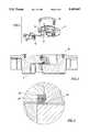
- FIG. 10is a partial view, some of which is in cross section, of a packer element used in a pipe ram.
- FIG. 11is a close-up view of a portion of the packer element shown in FIG. 10.
- the designing of a bonded assembly with elastomeric materialsis predicated on the use of the assembly, its operating environment and other factors.
- a primermay also be used.
- chemical and/or mechanical meansare often employed to clean and otherwise prepare the surfaces to be bonded.
- the adhesive materialscan be applied in a number of different ways, including the use of a brush, sprayer, dipping process, or a roller. Controlled temperature and a clean environment during the application and curing stages are also important to assure that the surfaces and the bonding materials remain uncontaminated.
- a mechanical securement in addition to chemical bondingresults in a more satisfactory assembly.
- One such applicationinvolves the bonding of the elastomer or rubber parts in a blowout preventer.
- an upper block carrier assembly 8having a packer comprising basically two elastomer or rubber assemblies, namely, upper seal 10 and lateral T-seal 12.
- the other major parts illustrated in FIG. 1are upper blade carrier 14 and upper shear blade 16. The other parts are not further identified, but the assembly of these parts generally utilizes bolts and is well-known in the art.
- upper blade carrier assembly 8appears generally in cross section in FIG. 2.
- upper blade carrier assembly 8is employed with a lower blade carrier assembly 18.
- the shearing operation performed by these two assembliesutilizes a twin V-blade arrangement with sharp rake angles to crimp, tension, and shear a drill pipe.
- Shearing pipeis usually done in adverse conditions and at a recommended maximum operating pressure on the order of 3,000 psi. Repeatable shearing operations are required of the shear ram components.
- the lateral T-sealis a complex structure made up of two different types of nitrile rubber compounds for upper elastomer section 20 and lower elastomer T-section 22, respectively, nylon or other non-elastomer plastic central anti-extrusion bar 24 and end anti-extrusion pieces 26, and metal alignment pins 28. As shown in FIGS. 4, 6 and 7, all of the pieces have heretofore been bonded to each other using adhesive appropriate to the application. Bonding agents that have been preferably employed are Chemlock 205 and Chemlock 220, which are products of Lord Elastomer Products of Erie, Pennsylvania. Other equivalent bonding agents can also be used.
- anti-extrusion bar 24aincludes accommodating rivet holes for mating with rivets 30.
- a rivet 30preferably includes an enlarged base 32 contiguous to the main body of section 22a, a narrow, reduced diameter center section 34, and an enlarged outer end section 36.
- a preferred commercial compound for use as this bonding lineis either Chemlock 205 or Chemlock 220.
- the bonding achievedis both chemical bonding along the bonding line interface between the elastomer and the other material and mechanical bonding, adding significant extra strength to the overall bond.
- the elastomeric rivetshrinks and forms a tightly "riveted" connection with the other material of the junction.
- the shrinking of the rivetcompresses the materials together and thereby enhances the adhesive bond line.
- the elastomer rivetalso provides an extra shear area that further strengthens the overall assembly of parts as the elastomer is distorted during operational loading.
- a portion of a packer element 10 employed in a pipe ram assemblyincludes a metal plate 40 adhered or bonded to elastomer 42.
- a plastic insert 44is employed in an area at a corner between the elastomer and the metal plate that is chemically and mechanically bonded by the use of rivet 46.
- the purpose of this insertis explained more fully in U.S. Pat. No. 5,180,137, issued Jan. 19, 1993 in the names of Douglas W. Carlson, et al., which patent is commonly assigned herewith and incorporated by reference for all purposes.
- insert 44is a non-elastomer, relatively rigid strip that is bonded to elastomer 42, preferably a nitrile rubber material, but is not bonded to metal plate 40. Because the interface surface between insert 44 and elastomer 42 is a relatively small area, the retention force by chemical bonding alone is greatly enhanced by the use of rivet 46, which not only enhances bonding in the manner previously described for rivets 30 above, but adds bonding strength in this case by significantly increasing the amount of surface area subject to coating with the bonding agent. Rivet 46 is similar to rivet 30 described above although, in this case, the body attached to the head has a uniform diameter dimension. Otherwise, the bonding accomplished by the use of the integral elastomer rivet structure is the same as discussed above.
- the interface surface between elastomer 42 and metal plate 40is much greater than the interface without the use of rivet 46 between elastomer 42 and insert 44. Therefore, although the bonding of elastomer 42 to metal plate 40 could be enhanced by the use of similar integral rubber rivets, it has not been necessary in this case.
- the environment that has been describedis the environment encountered by the nitrile rubber and other material complex parts of a typical blowout preventer.
- the inventioncan also be used in other applications, especially where the operating conditions are extremely severe and include high pressures and/or high temperatures.
Landscapes
- Life Sciences & Earth Sciences (AREA)
- Engineering & Computer Science (AREA)
- Geology (AREA)
- Mining & Mineral Resources (AREA)
- Physics & Mathematics (AREA)
- Environmental & Geological Engineering (AREA)
- Fluid Mechanics (AREA)
- General Life Sciences & Earth Sciences (AREA)
- Geochemistry & Mineralogy (AREA)
- Lining Or Joining Of Plastics Or The Like (AREA)
Abstract
Description
Claims (2)
Priority Applications (5)
| Application Number | Priority Date | Filing Date | Title |
|---|---|---|---|
| US08/104,371US5405467A (en) | 1993-08-09 | 1993-08-09 | Rubber riveting of molded parts |
| DE69414506TDE69414506T2 (en) | 1993-08-09 | 1994-08-09 | Rubber rental of cast parts for breakout valves |
| EP94112423AEP0643195B1 (en) | 1993-08-09 | 1994-08-09 | Rubber riveting of molded parts for blow-out preventers |
| NO942956ANO306636B1 (en) | 1993-08-09 | 1994-08-09 | Packing for a drill securing valve and method for mechanically and chemically bonding a plastic or metal part in a drill securing valve gasket to an elastomeric part |
| US08/617,674US5906375A (en) | 1993-08-09 | 1996-02-27 | Rubber riveting of molded parts |
Applications Claiming Priority (1)
| Application Number | Priority Date | Filing Date | Title |
|---|---|---|---|
| US08/104,371US5405467A (en) | 1993-08-09 | 1993-08-09 | Rubber riveting of molded parts |
Related Child Applications (1)
| Application Number | Title | Priority Date | Filing Date |
|---|---|---|---|
| US39943395ADivision | 1993-08-09 | 1995-03-07 |
Publications (1)
| Publication Number | Publication Date |
|---|---|
| US5405467Atrue US5405467A (en) | 1995-04-11 |
Family
ID=22300147
Family Applications (2)
| Application Number | Title | Priority Date | Filing Date |
|---|---|---|---|
| US08/104,371Expired - LifetimeUS5405467A (en) | 1993-08-09 | 1993-08-09 | Rubber riveting of molded parts |
| US08/617,674Expired - LifetimeUS5906375A (en) | 1993-08-09 | 1996-02-27 | Rubber riveting of molded parts |
Family Applications After (1)
| Application Number | Title | Priority Date | Filing Date |
|---|---|---|---|
| US08/617,674Expired - LifetimeUS5906375A (en) | 1993-08-09 | 1996-02-27 | Rubber riveting of molded parts |
Country Status (4)
| Country | Link |
|---|---|
| US (2) | US5405467A (en) |
| EP (1) | EP0643195B1 (en) |
| DE (1) | DE69414506T2 (en) |
| NO (1) | NO306636B1 (en) |
Cited By (10)
| Publication number | Priority date | Publication date | Assignee | Title |
|---|---|---|---|---|
| US5713581A (en)* | 1994-10-03 | 1998-02-03 | Hydril Company | Fibrous seal for blowout preventer |
| US5944110A (en)* | 1997-09-11 | 1999-08-31 | Cooper Cameron Corporation | Variable bore ram packer for a ram type blowout preventer |
| US6256118B1 (en) | 1998-05-22 | 2001-07-03 | Eastman Kodak Company | Ultraviolet curable riveting of precision aligned components |
| US6723105B1 (en)* | 1997-05-09 | 2004-04-20 | Prism Enterprises Lp | Obstetrical vacuum extractor cup with soft molded lip |
| US20050042023A1 (en)* | 2003-08-20 | 2005-02-24 | Jones Steve R. | Structural assemblies using integrally molded, and welded mechanically locking z-pins |
| US20080006625A1 (en)* | 2006-07-03 | 2008-01-10 | Kautex Textron Gmbh & Co. Kg | Method for producing a container of thermoplastic material |
| US20090065073A1 (en)* | 2007-09-11 | 2009-03-12 | Davis David B | Metal sealing disk having an elastomeric backing for use with fluid regulators |
| US20170130550A1 (en)* | 2015-11-09 | 2017-05-11 | Hydril USA Distribution LLC | Blind shear ram |
| US20170218717A1 (en)* | 2014-08-07 | 2017-08-03 | Shell Oil Company | Kinetic shear ram |
| CN113574244A (en)* | 2019-04-10 | 2021-10-29 | 哈利伯顿能源服务公司 | Protective Barrier Coatings for Improving Adhesive Integrity in Downhole Exposures |
Families Citing this family (9)
| Publication number | Priority date | Publication date | Assignee | Title |
|---|---|---|---|---|
| US6394460B1 (en)* | 1999-12-17 | 2002-05-28 | Tuboscope I/P | One-piece ram element block for wireline blowout preventers |
| US20030155721A1 (en)* | 2002-02-15 | 2003-08-21 | Zheng Qiu Shi | Metal-to-metal seal and method of making same |
| US6719042B2 (en) | 2002-07-08 | 2004-04-13 | Varco Shaffer, Inc. | Shear ram assembly |
| US20060213143A1 (en)* | 2005-03-24 | 2006-09-28 | Mcintyre Dan | Shingles and methods of producing shingles |
| US8844613B2 (en)* | 2011-12-28 | 2014-09-30 | Hydrill USA Manufacturing LLC | Shear blade and method of attachment to shear rams |
| JP5903632B2 (en)* | 2012-09-07 | 2016-04-13 | パナソニックIpマネジメント株式会社 | Plate-shaped housing member and insert injection molding method thereof |
| US10655420B2 (en)* | 2017-03-21 | 2020-05-19 | Baker Hughes, A Ge Company, Llc | Blowout prevention system including blind shear ram |
| US10370927B2 (en)* | 2017-03-30 | 2019-08-06 | General Electric Company | Blowout prevention system including blind shear ram |
| US20180283560A1 (en)* | 2017-03-30 | 2018-10-04 | General Electric Company | Blowout prevention system including blind shear ram |
Citations (10)
| Publication number | Priority date | Publication date | Assignee | Title |
|---|---|---|---|---|
| US2604903A (en)* | 1946-09-23 | 1952-07-29 | Nat Supply Co | Ram packing element for blowout preventers |
| US3086517A (en)* | 1961-07-03 | 1963-04-23 | Clarence C Dunkle | Hydrotherapy pad |
| US3132412A (en)* | 1964-05-12 | Process for manufacturing a lever assembly | ||
| US4456215A (en)* | 1982-05-07 | 1984-06-26 | Bowen Tools, Inc. | Inner seal and support rod assembly for high pressure blowout preventers |
| US4541639A (en)* | 1982-09-16 | 1985-09-17 | Cameron Iron Works, Inc. | Ram-type blowout preventer with improved ram front packer |
| US4684418A (en)* | 1983-01-19 | 1987-08-04 | Dayco Products, Inc. | Method of making a holddown bar for a hatch cover of a railroad car |
| US4858882A (en)* | 1987-05-27 | 1989-08-22 | Beard Joseph O | Blowout preventer with radial force limiter |
| US5160474A (en)* | 1990-12-21 | 1992-11-03 | Cadillac Rubber & Plastics, Inc. | Overmolded gasket, heat exchanger tank incorporating the same and method for making the same |
| US5180137A (en)* | 1991-10-02 | 1993-01-19 | Hydril Company | Ram type blowout preventer having improved ram front packings |
| US5195581A (en)* | 1992-05-15 | 1993-03-23 | General Motors Corporation | Snap on radiator tank |
Family Cites Families (11)
| Publication number | Priority date | Publication date | Assignee | Title |
|---|---|---|---|---|
| GB1041916A (en)* | 1964-06-22 | 1966-09-07 | Walker & Co James Ltd | Improvements in or relating to annular fluid pressure seals |
| US3848880A (en)* | 1972-06-09 | 1974-11-19 | Tanner Eng Co | Fluid seal |
| US4310139A (en)* | 1980-04-04 | 1982-01-12 | Cameron Iron Works, Inc. | Annular blowout preventer |
| US4339107A (en)* | 1981-08-17 | 1982-07-13 | Oil Tool Molded Products, Inc. | Well blowout preventer packer assembly and packer modules therefor |
| US4447038A (en)* | 1982-02-19 | 1984-05-08 | The Mead Corporation | Blow-out protector packer element |
| US4431704A (en)* | 1983-03-29 | 1984-02-14 | Regal International, Inc. | Composition for blowout preventer |
| US4690411A (en)* | 1985-12-23 | 1987-09-01 | Winkle Denzal W Van | Bonded mechanically inner connected seal arrangement for a blowout preventer |
| US4635945A (en)* | 1986-03-21 | 1987-01-13 | Microdot Inc. | Anti-extrusion seal with primary and secondary complementary elements |
| US4822671A (en)* | 1987-12-31 | 1989-04-18 | Gencorp Inc. | Heat riveting rubber for effecting a mechanical lock |
| US4844406A (en)* | 1988-02-09 | 1989-07-04 | Double-E Inc. | Blowout preventer |
| US5005802A (en)* | 1990-02-01 | 1991-04-09 | Cooper Industries, Inc. | Variable bore packer for a ram type blowout preventer |
- 1993
- 1993-08-09USUS08/104,371patent/US5405467A/ennot_activeExpired - Lifetime
- 1994
- 1994-08-09NONO942956Apatent/NO306636B1/enunknown
- 1994-08-09EPEP94112423Apatent/EP0643195B1/ennot_activeExpired - Lifetime
- 1994-08-09DEDE69414506Tpatent/DE69414506T2/ennot_activeExpired - Lifetime
- 1996
- 1996-02-27USUS08/617,674patent/US5906375A/ennot_activeExpired - Lifetime
Patent Citations (10)
| Publication number | Priority date | Publication date | Assignee | Title |
|---|---|---|---|---|
| US3132412A (en)* | 1964-05-12 | Process for manufacturing a lever assembly | ||
| US2604903A (en)* | 1946-09-23 | 1952-07-29 | Nat Supply Co | Ram packing element for blowout preventers |
| US3086517A (en)* | 1961-07-03 | 1963-04-23 | Clarence C Dunkle | Hydrotherapy pad |
| US4456215A (en)* | 1982-05-07 | 1984-06-26 | Bowen Tools, Inc. | Inner seal and support rod assembly for high pressure blowout preventers |
| US4541639A (en)* | 1982-09-16 | 1985-09-17 | Cameron Iron Works, Inc. | Ram-type blowout preventer with improved ram front packer |
| US4684418A (en)* | 1983-01-19 | 1987-08-04 | Dayco Products, Inc. | Method of making a holddown bar for a hatch cover of a railroad car |
| US4858882A (en)* | 1987-05-27 | 1989-08-22 | Beard Joseph O | Blowout preventer with radial force limiter |
| US5160474A (en)* | 1990-12-21 | 1992-11-03 | Cadillac Rubber & Plastics, Inc. | Overmolded gasket, heat exchanger tank incorporating the same and method for making the same |
| US5180137A (en)* | 1991-10-02 | 1993-01-19 | Hydril Company | Ram type blowout preventer having improved ram front packings |
| US5195581A (en)* | 1992-05-15 | 1993-03-23 | General Motors Corporation | Snap on radiator tank |
Non-Patent Citations (2)
| Title |
|---|
| Machinery s Handbook, 23rd Edition, Edited by Henry H. Ryffel, Industrial Press, Inc., New York, N.Y., 1988, pp. 1259 1276.* |
| Machinery's Handbook, 23rd Edition, Edited by Henry H. Ryffel, Industrial Press, Inc., New York, N.Y., 1988, pp. 1259-1276. |
Cited By (13)
| Publication number | Priority date | Publication date | Assignee | Title |
|---|---|---|---|---|
| US5713581A (en)* | 1994-10-03 | 1998-02-03 | Hydril Company | Fibrous seal for blowout preventer |
| US6723105B1 (en)* | 1997-05-09 | 2004-04-20 | Prism Enterprises Lp | Obstetrical vacuum extractor cup with soft molded lip |
| US20040167541A1 (en)* | 1997-05-09 | 2004-08-26 | Hulse Jerry Dwayne | Obstetrical vacuum extractor cup with soft molded lip |
| US5944110A (en)* | 1997-09-11 | 1999-08-31 | Cooper Cameron Corporation | Variable bore ram packer for a ram type blowout preventer |
| US6256118B1 (en) | 1998-05-22 | 2001-07-03 | Eastman Kodak Company | Ultraviolet curable riveting of precision aligned components |
| US20050042023A1 (en)* | 2003-08-20 | 2005-02-24 | Jones Steve R. | Structural assemblies using integrally molded, and welded mechanically locking z-pins |
| US20080006625A1 (en)* | 2006-07-03 | 2008-01-10 | Kautex Textron Gmbh & Co. Kg | Method for producing a container of thermoplastic material |
| US9023264B2 (en)* | 2006-07-03 | 2015-05-05 | Kautex Textron Gmbh & Co. Kg | Method for producing a container of thermoplastic material |
| US20090065073A1 (en)* | 2007-09-11 | 2009-03-12 | Davis David B | Metal sealing disk having an elastomeric backing for use with fluid regulators |
| US20170218717A1 (en)* | 2014-08-07 | 2017-08-03 | Shell Oil Company | Kinetic shear ram |
| US20170130550A1 (en)* | 2015-11-09 | 2017-05-11 | Hydril USA Distribution LLC | Blind shear ram |
| US10550660B2 (en)* | 2015-11-09 | 2020-02-04 | Hydril USA Distribution LLC | Blind shear ram |
| CN113574244A (en)* | 2019-04-10 | 2021-10-29 | 哈利伯顿能源服务公司 | Protective Barrier Coatings for Improving Adhesive Integrity in Downhole Exposures |
Also Published As
| Publication number | Publication date |
|---|---|
| DE69414506D1 (en) | 1998-12-17 |
| DE69414506T2 (en) | 1999-04-29 |
| EP0643195A2 (en) | 1995-03-15 |
| NO942956D0 (en) | 1994-08-09 |
| EP0643195B1 (en) | 1998-11-11 |
| EP0643195A3 (en) | 1995-11-02 |
| NO942956L (en) | 1995-02-10 |
| NO306636B1 (en) | 1999-11-29 |
| US5906375A (en) | 1999-05-25 |
Similar Documents
| Publication | Publication Date | Title |
|---|---|---|
| US5405467A (en) | Rubber riveting of molded parts | |
| DE69200259T2 (en) | Expandable sealing arrangement. | |
| CA1104604A (en) | Circumferentially compressed piston ring assembly and method | |
| US4478543A (en) | Blind rivet | |
| US6302405B1 (en) | Anti-extrusion seal | |
| CN1107169C (en) | Closed rivet and assembly method thereof | |
| JPH04258574A (en) | Package assembly | |
| JPS6261803B2 (en) | ||
| CA2107739A1 (en) | Variable bore packer for a ram-type blowout preventer | |
| DE69509770T2 (en) | BEARING ARRANGEMENT WITH INCLUDED PTFE BEARING BUSH | |
| CN102257301B (en) | The method of the sealant strip improved and formation lap joint | |
| US9897158B2 (en) | Adapter for an isolation mount design | |
| WO2002090137A3 (en) | Sealing extruded section for being mounted on a projecting part of a structure, blank of said section and method for fixing said blank on the projecting part | |
| DE69912121T2 (en) | EASY TO INSTALL MEMBRANE | |
| US4756784A (en) | Method of making pipe-joint gasket | |
| DE102004020586A1 (en) | Blind rivet with adhesive for joining and adhesive filling process | |
| US4700954A (en) | Radially extensible joint packing with fiber filled elastomeric core | |
| EP0978678B1 (en) | Conductive pipe or cable clamp | |
| US8764021B2 (en) | Seal assembly | |
| US11674596B2 (en) | Seal with first elastomeric element and second elastomeric element | |
| US5152557A (en) | Plastic coupling with ring for adhesion to a tubular member | |
| AU668792B2 (en) | Blowout preventer with removable packer | |
| DE3719189A1 (en) | Sealing ring | |
| EP1323937B1 (en) | Ball joint and its manufacturing process | |
| US4796927A (en) | Mobile joint for connectors |
Legal Events
| Date | Code | Title | Description |
|---|---|---|---|
| AS | Assignment | Owner name:HYDRIL COMPANY Free format text:ASSIGNMENT OF ASSIGNORS INTEREST;ASSIGNORS:YOUNG, KENNETH D.;SIMONS, STEPHEN P.;REEL/FRAME:006657/0165 Effective date:19930804 | |
| STCF | Information on status: patent grant | Free format text:PATENTED CASE | |
| FEPP | Fee payment procedure | Free format text:PAYOR NUMBER ASSIGNED (ORIGINAL EVENT CODE: ASPN); ENTITY STATUS OF PATENT OWNER: LARGE ENTITY | |
| AS | Assignment | Owner name:CHASE BANK OF TEXAS, NATIONAL ASSOC., AS AGENT, TE Free format text:SECURITY INTEREST;ASSIGNOR:HYDRIL COMPANY;REEL/FRAME:009123/0016 Effective date:19980323 | |
| FPAY | Fee payment | Year of fee payment:4 | |
| FEPP | Fee payment procedure | Free format text:PAYOR NUMBER ASSIGNED (ORIGINAL EVENT CODE: ASPN); ENTITY STATUS OF PATENT OWNER: LARGE ENTITY Free format text:PAYER NUMBER DE-ASSIGNED (ORIGINAL EVENT CODE: RMPN); ENTITY STATUS OF PATENT OWNER: LARGE ENTITY | |
| FPAY | Fee payment | Year of fee payment:8 | |
| REMI | Maintenance fee reminder mailed | ||
| AS | Assignment | Owner name:HYDRIL COMPANY LP, TEXAS Free format text:ASSIGNMENT OF ASSIGNORS INTEREST;ASSIGNOR:HYDRIL COMPANY;REEL/FRAME:014499/0197 Effective date:20020101 | |
| AS | Assignment | Owner name:HYDRIL COMPANY LP, TEXAS Free format text:ASSIGNMENT OF ASSIGNORS INTEREST;ASSIGNOR:HYDRIL COMPANY;REEL/FRAME:014763/0830 Effective date:20030922 | |
| AS | Assignment | Owner name:HYDRIL COMPANY, TEXAS Free format text:RELEASE OF LIEN;ASSIGNOR:CHASE BANK OF TEXAS, NATIONAL ASSOCIATION;REEL/FRAME:014734/0860 Effective date:20040604 | |
| FPAY | Fee payment | Year of fee payment:12 | |
| AS | Assignment | Owner name:HYDRIL GENERAL LLC, TEXAS Free format text:MERGER;ASSIGNOR:HYDRIL COMPANY LP;REEL/FRAME:020710/0717 Effective date:20070629 Owner name:HYDRIL LLC, TEXAS Free format text:CHANGE OF NAME;ASSIGNOR:HDRYIL GENERAL LLC;REEL/FRAME:020710/0950 Effective date:20070719 Owner name:HYDRIL GENERAL LLC,TEXAS Free format text:MERGER;ASSIGNOR:HYDRIL COMPANY LP;REEL/FRAME:020710/0717 Effective date:20070629 Owner name:HYDRIL LLC,TEXAS Free format text:CHANGE OF NAME;ASSIGNOR:HDRYIL GENERAL LLC;REEL/FRAME:020710/0950 Effective date:20070719 | |
| AS | Assignment | Owner name:HYDRIL USA MANUFACTURING LLC, TEXAS Free format text:ASSIGNMENT OF ASSIGNORS INTEREST;ASSIGNOR:HYDRIL LLC;REEL/FRAME:021050/0491 Effective date:20080401 Owner name:HYDRIL USA MANUFACTURING LLC,TEXAS Free format text:ASSIGNMENT OF ASSIGNORS INTEREST;ASSIGNOR:HYDRIL LLC;REEL/FRAME:021050/0491 Effective date:20080401 |