US5405400A - Joint prosthesis enabling rotary circumduction - Google Patents
Joint prosthesis enabling rotary circumductionDownload PDFInfo
- Publication number
- US5405400A US5405400AUS08/132,296US13229693AUS5405400AUS 5405400 AUS5405400 AUS 5405400AUS 13229693 AUS13229693 AUS 13229693AUS 5405400 AUS5405400 AUS 5405400A
- Authority
- US
- United States
- Prior art keywords
- articulating
- stem
- bone
- metacarpal
- prosthesis
- Prior art date
- Legal status (The legal status is an assumption and is not a legal conclusion. Google has not performed a legal analysis and makes no representation as to the accuracy of the status listed.)
- Expired - Lifetime
Links
Images

Classifications
- A—HUMAN NECESSITIES
- A61—MEDICAL OR VETERINARY SCIENCE; HYGIENE
- A61F—FILTERS IMPLANTABLE INTO BLOOD VESSELS; PROSTHESES; DEVICES PROVIDING PATENCY TO, OR PREVENTING COLLAPSING OF, TUBULAR STRUCTURES OF THE BODY, e.g. STENTS; ORTHOPAEDIC, NURSING OR CONTRACEPTIVE DEVICES; FOMENTATION; TREATMENT OR PROTECTION OF EYES OR EARS; BANDAGES, DRESSINGS OR ABSORBENT PADS; FIRST-AID KITS
- A61F2/00—Filters implantable into blood vessels; Prostheses, i.e. artificial substitutes or replacements for parts of the body; Appliances for connecting them with the body; Devices providing patency to, or preventing collapsing of, tubular structures of the body, e.g. stents
- A61F2/02—Prostheses implantable into the body
- A61F2/30—Joints
- A61F2/42—Joints for wrists or ankles; for hands, e.g. fingers; for feet, e.g. toes
- A61F2/4241—Joints for wrists or ankles; for hands, e.g. fingers; for feet, e.g. toes for hands, e.g. fingers
- A—HUMAN NECESSITIES
- A61—MEDICAL OR VETERINARY SCIENCE; HYGIENE
- A61F—FILTERS IMPLANTABLE INTO BLOOD VESSELS; PROSTHESES; DEVICES PROVIDING PATENCY TO, OR PREVENTING COLLAPSING OF, TUBULAR STRUCTURES OF THE BODY, e.g. STENTS; ORTHOPAEDIC, NURSING OR CONTRACEPTIVE DEVICES; FOMENTATION; TREATMENT OR PROTECTION OF EYES OR EARS; BANDAGES, DRESSINGS OR ABSORBENT PADS; FIRST-AID KITS
- A61F2/00—Filters implantable into blood vessels; Prostheses, i.e. artificial substitutes or replacements for parts of the body; Appliances for connecting them with the body; Devices providing patency to, or preventing collapsing of, tubular structures of the body, e.g. stents
- A61F2/02—Prostheses implantable into the body
- A61F2/30—Joints
- A61F2002/30001—Additional features of subject-matter classified in A61F2/28, A61F2/30 and subgroups thereof
- A61F2002/30108—Shapes
- A61F2002/30199—Three-dimensional shapes
- A61F2002/30301—Three-dimensional shapes saddle-shaped
- A—HUMAN NECESSITIES
- A61—MEDICAL OR VETERINARY SCIENCE; HYGIENE
- A61F—FILTERS IMPLANTABLE INTO BLOOD VESSELS; PROSTHESES; DEVICES PROVIDING PATENCY TO, OR PREVENTING COLLAPSING OF, TUBULAR STRUCTURES OF THE BODY, e.g. STENTS; ORTHOPAEDIC, NURSING OR CONTRACEPTIVE DEVICES; FOMENTATION; TREATMENT OR PROTECTION OF EYES OR EARS; BANDAGES, DRESSINGS OR ABSORBENT PADS; FIRST-AID KITS
- A61F2/00—Filters implantable into blood vessels; Prostheses, i.e. artificial substitutes or replacements for parts of the body; Appliances for connecting them with the body; Devices providing patency to, or preventing collapsing of, tubular structures of the body, e.g. stents
- A61F2/02—Prostheses implantable into the body
- A61F2/30—Joints
- A61F2/30767—Special external or bone-contacting surface, e.g. coating for improving bone ingrowth
- A61F2/30771—Special external or bone-contacting surface, e.g. coating for improving bone ingrowth applied in original prostheses, e.g. holes or grooves
- A61F2002/30878—Special external or bone-contacting surface, e.g. coating for improving bone ingrowth applied in original prostheses, e.g. holes or grooves with non-sharp protrusions, for instance contacting the bone for anchoring, e.g. keels, pegs, pins, posts, shanks, stems, struts
- A—HUMAN NECESSITIES
- A61—MEDICAL OR VETERINARY SCIENCE; HYGIENE
- A61F—FILTERS IMPLANTABLE INTO BLOOD VESSELS; PROSTHESES; DEVICES PROVIDING PATENCY TO, OR PREVENTING COLLAPSING OF, TUBULAR STRUCTURES OF THE BODY, e.g. STENTS; ORTHOPAEDIC, NURSING OR CONTRACEPTIVE DEVICES; FOMENTATION; TREATMENT OR PROTECTION OF EYES OR EARS; BANDAGES, DRESSINGS OR ABSORBENT PADS; FIRST-AID KITS
- A61F2/00—Filters implantable into blood vessels; Prostheses, i.e. artificial substitutes or replacements for parts of the body; Appliances for connecting them with the body; Devices providing patency to, or preventing collapsing of, tubular structures of the body, e.g. stents
- A61F2/02—Prostheses implantable into the body
- A61F2/30—Joints
- A61F2/42—Joints for wrists or ankles; for hands, e.g. fingers; for feet, e.g. toes
- A61F2/4241—Joints for wrists or ankles; for hands, e.g. fingers; for feet, e.g. toes for hands, e.g. fingers
- A61F2002/4256—Joints for wrists or ankles; for hands, e.g. fingers; for feet, e.g. toes for hands, e.g. fingers for carpo-metacarpal joints, i.e. CMC joints
- A61F2002/4258—Joints for wrists or ankles; for hands, e.g. fingers; for feet, e.g. toes for hands, e.g. fingers for carpo-metacarpal joints, i.e. CMC joints for trapezo-metacarpal joints of thumbs
- A—HUMAN NECESSITIES
- A61—MEDICAL OR VETERINARY SCIENCE; HYGIENE
- A61F—FILTERS IMPLANTABLE INTO BLOOD VESSELS; PROSTHESES; DEVICES PROVIDING PATENCY TO, OR PREVENTING COLLAPSING OF, TUBULAR STRUCTURES OF THE BODY, e.g. STENTS; ORTHOPAEDIC, NURSING OR CONTRACEPTIVE DEVICES; FOMENTATION; TREATMENT OR PROTECTION OF EYES OR EARS; BANDAGES, DRESSINGS OR ABSORBENT PADS; FIRST-AID KITS
- A61F2230/00—Geometry of prostheses classified in groups A61F2/00 - A61F2/26 or A61F2/82 or A61F9/00 or A61F11/00 or subgroups thereof
- A61F2230/0063—Three-dimensional shapes
- A61F2230/0073—Quadric-shaped
- A61F2230/008—Quadric-shaped paraboloidal
- A—HUMAN NECESSITIES
- A61—MEDICAL OR VETERINARY SCIENCE; HYGIENE
- A61F—FILTERS IMPLANTABLE INTO BLOOD VESSELS; PROSTHESES; DEVICES PROVIDING PATENCY TO, OR PREVENTING COLLAPSING OF, TUBULAR STRUCTURES OF THE BODY, e.g. STENTS; ORTHOPAEDIC, NURSING OR CONTRACEPTIVE DEVICES; FOMENTATION; TREATMENT OR PROTECTION OF EYES OR EARS; BANDAGES, DRESSINGS OR ABSORBENT PADS; FIRST-AID KITS
- A61F2230/00—Geometry of prostheses classified in groups A61F2/00 - A61F2/26 or A61F2/82 or A61F9/00 or A61F11/00 or subgroups thereof
- A61F2230/0063—Three-dimensional shapes
- A61F2230/0095—Saddle-shaped
- A—HUMAN NECESSITIES
- A61—MEDICAL OR VETERINARY SCIENCE; HYGIENE
- A61F—FILTERS IMPLANTABLE INTO BLOOD VESSELS; PROSTHESES; DEVICES PROVIDING PATENCY TO, OR PREVENTING COLLAPSING OF, TUBULAR STRUCTURES OF THE BODY, e.g. STENTS; ORTHOPAEDIC, NURSING OR CONTRACEPTIVE DEVICES; FOMENTATION; TREATMENT OR PROTECTION OF EYES OR EARS; BANDAGES, DRESSINGS OR ABSORBENT PADS; FIRST-AID KITS
- A61F2310/00—Prostheses classified in A61F2/28 or A61F2/30 - A61F2/44 being constructed from or coated with a particular material
- A61F2310/00005—The prosthesis being constructed from a particular material
- A61F2310/00011—Metals or alloys
- A61F2310/00023—Titanium or titanium-based alloys, e.g. Ti-Ni alloys
- A—HUMAN NECESSITIES
- A61—MEDICAL OR VETERINARY SCIENCE; HYGIENE
- A61F—FILTERS IMPLANTABLE INTO BLOOD VESSELS; PROSTHESES; DEVICES PROVIDING PATENCY TO, OR PREVENTING COLLAPSING OF, TUBULAR STRUCTURES OF THE BODY, e.g. STENTS; ORTHOPAEDIC, NURSING OR CONTRACEPTIVE DEVICES; FOMENTATION; TREATMENT OR PROTECTION OF EYES OR EARS; BANDAGES, DRESSINGS OR ABSORBENT PADS; FIRST-AID KITS
- A61F2310/00—Prostheses classified in A61F2/28 or A61F2/30 - A61F2/44 being constructed from or coated with a particular material
- A61F2310/00005—The prosthesis being constructed from a particular material
- A61F2310/00011—Metals or alloys
- A61F2310/00029—Cobalt-based alloys, e.g. Co-Cr alloys or Vitallium
Definitions
- the inventionrelates to joint prosthesis particularly adapted for replacing a joint, such as the joint between the first metacarpal and the trapezium of the human hand, in which one elongated bone (e.g., the first metacarpal) is normally permitted a substantial degree of rotary circumduction with respect to a second bone (e.g., the trapezium), without substantial rotation of the elongated bone about its axis.
- a jointsuch as the joint between the first metacarpal and the trapezium of the human hand
- one elongated bonee.g., the first metacarpal
- a second bonee.g., the trapezium
- the present inventionprovides a joint prosthesis particularly suited for use in replacing the joint between an elongated first bone such as the first metacarpal bone and a second bone such as the trapezium with respect to which the first bone should be permitted a substantial degree of rotary circumduction without substantial rotation about its longitudinal axis.
- the prosthesisincludes a first member having a coupling portion enabling attachment of the first member to an elongated bone and a second member having a connector adapted for connection of the second member to a second bone.
- the first and second membershave respective articulating saddle-shaped surfaces configured and sized to articulate with each other to enable the long bone to move in rotary circumduction with respect to the other bone.
- the saddle-shaped articulating surfacesare substantially congruent in shape to maintain mutual substantially surface-to-surface contact over the range of normal articular movement between the bones.
- the articulating surfacespreferably have approximately the same area so that when they are aligned, each articulating surface substantially completely overlaps the other.
- the prosthesisis adapted in size and shape to replace the articulating joint between the trapezium and the first metacarpal.
- the first memberhas a stem that is asymmetric with respect to its articulating surface, the stem being received in the first metacarpal bone in a preferred orientation. That orientation positions the saddle-shaped articulating surface of the first member with respect to that of the second member such that the pivot axis for adduction/abduction of the first metacarpal is proximal of the respective articulating surfaces, and the pivot axis for dorsal/volar movement of the first metacarpal is distal of the articulating surfaces.
- Articulating portions of the first and second memberseach have supporting surfaces that confront surgically prepared surfaces of the bones to which they are to be attached.
- the supporting surface of the articulating portion of the second membermay be recessed to receive the surgically prepared surface of the second bone.
- the "elongated bone”may particularly be the first metacarpal which normally articulates with the trapezium. This joint affords the first metacarpal a substantial degree of rotary circumduction in which the first metacarpal may be rotated about the joint to sweep out a roughly conical shape, the cone having a included angle of at least about 15° and ranging generally between about 15° and 30°.
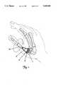
- FIG. 1is a view of bones of the hand and, wrist and within which has been implanted a prosthesis of the invention, the hand being shown in phantom lines;
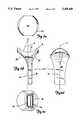
- FIGS. 2A, 2B, 2C, and 2Dare orthographic views of a first member of a prosthesis of the invention.
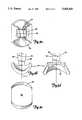
- FIGS. 3A, 3B, 3C, and 3Dare orthographic views of a second member of a prosthesis of the invention
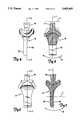
- FIG. 4is a plan view of the articulating members shown in FIGS. 3A-3D and 2A-2D;
- FIG. 5is a cross sectional view taken along line 5--5 of FIG. 4;
- FIG. 6is a plan view of the prosthesis shown in FIG. 4, taken from the right hand side of FIG. 4;
- FIG. 7is a cross sectional view taken along line 7--7 of FIG. 6;
- FIG. 8is a perspective view showing a step in the implantation of the member shown in FIGS. 3A-3D.
- FIG. 9is a perspective view showing an alternate step in implantation of the member shown in FIGS. 3A-3D.
- prosthesis of the inventionwill be described in terms of the first metacarpal/trapezium joint.
- the first member of the prosthesishas (as implanted) distal and proximal ends, the distal end comprising an elongated stem that is appropriately sized and shaped to fit within the surgically exposed marrow recess in the proximal end portion of the first metacarpal.
- the first memberincludes an enlarged head provided with a proximally-facing saddle-shaped articulation surface.
- the stemmay be offset slightly so as to provide a slightly convex aspect to the volar surface of the first metacarpal bone.
- the second memberwhich is to be carried by the trapezium, has a proximally extending stem for reception within the trapezium and an enlarged head bearing a distally facing saddle shaped articulating surface that is substantially congruent to the saddle-shaped surface of the first member. It is the saddle shaped articulating surfaces that enable the first metacarpal to enjoy a substantial degree of rotary circumduction with respect to the trapezium without permitting substantial rotation of the first metacarpal about its axis.
- the respective saddle-shaped articulating surfaces of the first and second membersmay be of different sizes or of different shapes, or both, to enable varying degrees of respective rotational movement between the first metacarpal and the trapezium.
- one of the saddle-shaped surfacesmay be more tightly or severly curved than the other, although they may substantially overlap each other.
- the trapeziumis designated "T” and the first metacarpal that articulates with the trapezium is designated "MC”.
- the first metacarpal and trapeziumare shown broken away adjacent their points of articulation, exposing respective first and second members 12, 14 of a prosthesis 10 of the invention.
- a first member 12is shown in orthographic views as having an elongated, somewhat flattened stem 16 and an enlarged proximal head 18, the head having a proximally presented saddle-shaped articulating surface 20.
- the surface 20may be considered a hyperbolic paraboloid.
- all points on the articulating surface 20can be viewed from a concave aspect as being formed upon a radius "r".
- Stem portion 16 of the first member 12 shown in FIGS. 2A-2Dis asymmetrical when viewed from the lateral aspect as in FIG. 2B with respect to the axis "K" of the hyperbolic paraboloid surface 20.
- the volar surface 22 of the stemis gently rounded at its proximal end 24, whereas the dorsal surface 26 is more tightly rounded at its proximal end.
- the stemis offset toward its dorsal surface, as shown best in FIG. 2B, so as to match more exactly the shape of the proximal end of the first metacarpal, the stem 16 being snugly received within the surgically exposed bone marrow cavity of the first metacarpal.
- the saddle-shaped surface 20presents a generally circular "footprint" or peripheral border 21 when viewed from the proximal end.
- FIGS. 3A-3Dshow a second member 14 of the prosthesis adapted for attachment to the trapezium.
- This memberincludes a stem 30 for reception within a recess surgically prepared in the trapezium, and a saddle-shaped articular surface 32 adapted to articulate with the surface 20 of the member shown in FIGS. 2A-2D.
- the surface 32is substantially congruent to the surface 20, and desirably is essentially perfectly congruent to the surface 20.
- the saddle-shaped surface 32is generally of the shape of a hyperbolic paraboloid.
- the surface 32When viewed from the distal end as in FIG. 3C, the surface 32 presents a "footprint" 33 which is substantially the same as that presented by the surface 20 shown in FIG. 2A.
- the surfaces 20 and 32When the surfaces 20 and 32 are in articulating contact with one another with their axes "K" and “L” generally aligned, the surfaces 32 and 20 cover one another over at least 70% of the larger saddle shaped area, preferably over at least 90% of that area so that at the limit of articulation, neither articulating surface extends beyond the other by more than about 10% of the surface area of the larger articulating surface.
- the stem 30 of member 14is generally symmetric to the axis "L" of the hyperbolic paraboloid surface 32.
- Stem 30has generally straight sides when viewed perpendicular to the volar or dorsal directions as in FIG. 3D, and these sides are designated generally as 34 in FIGS. 3A and 3D.
- the stemWhen viewed from its proximal end, as in FIG. 3A, the stem will be seen to be generally rectangular in cross section, and the walls 36 of the stem that are generally at fight angles to the walls 34 diverge proximally to form a generally dovetail shape as shown best in FIG. 3B.
- the symmetry of the stem 30 with respect to the axis of the saddle-shaped articulating surface 32enables the member 14 to be implanted in either the right hand or the left hand; that is, separate right and left hand prostheses are not required.
- FIGS. 4-7show articulation of the first and second members of the prosthesis.
- the second member 14 that is attached to the trapeziumis immovable, although in fact the trapezium is permitted some movement in normal motion of the hand for absorbing stress.
- articulation of the first metacarpal prosthesis member 12purely in flexion and extension occurs about an axis X (FIG. 5) spaced proximally from the articulating surfaces. Purely flexion/extension movement is shown by the arrow B in FIG. 7. This movement of the thumb is the primary movement involved in grasping and releasing objects from the hand.
- articulation of the member 12 in a near dorsal/volar direction(which may be described as abduction/adduction) takes place about an axis Y (FIG. 7) that is spaced distally from the articulating surfaces. Movement of the member 12 about this axis is shown by the arrow A in FIG. 5.
- Movement of the thumb first metacarpalis rarely purely flexion/extension or abduction/adduction, but rather is a combination of such movements.
- the pivot axis of the first member 12is neither X (FIG. 5) nor Y (FIG. 7), but rather dynamically moves between the axes X and Y.
- the pivot axiswill always lie along the axis K (FIG. 2B); that is, generally perpendicular to the articulating surface 20 of the first member.
- the axis of rotationwill move along the axis K between points X and Y.
- the orthopedic surgical procedures required to implant the prosthesis of the inventionare straightforward.
- surgical access to the trapezium/first metacarpal jointis had dorsally, the surgeon preserving as much soft tissue as possible.
- the proximal end of the first metacarpalis exposed and surgically sculpted to receive the stem 16 and head portion 18 of the first metacarpal prosthesis member 12.
- This proceduremay involve surgically enlarging the marrow cavity at the proximal end of the first metacarpal to appropriately receive the stem 16.
- FIG. 8shows a preferred procedure for attachment of the second member 14 to the trapezium T.
- the dorsal surface D of the trapeziumis surgically exposed and a cavity "C" is made in the trapezium, the cavity extending from the dorsal surface toward the volar surface of the trapezium through slightly over half the thickness of the trapezium.
- the cavity Cis open distally, as shown in FIG. 8.
- Sculpting of the distal surface of the trapeziumis performed as needed to enable the proximally facing surfaces of the head of member 14 to snugly contact the distal surface of the trapezium.
- the parallel surfaces 34 of the stemare snugly received between the confronting walls of the cavity C.
- the relatively long stem of the first metacarpal member 12is received within the marrow channel at the distal end of the first metacarpal.
- the stem 16is substantially narrower in the dorsal-volar direction, and this matches to some extent the physiologic configuration of the first metacarpal marrow cavity.
- the first member 12is received in the marrow cavity in only one orientation.
- the stem 30 of member 14is received in only one position in the trapezium, the saddle-shaped articulating surfaces of both members thus being positioned to articulate during normal movement of the first metacarpal. Bone cement is then used to hold both the first metacarpal portion 12 and the trapezium portion 14 in their respective bones.
- the surfaces of the stemsdesirably are shaped or treated to encourage bone ongrowth or ingrowth, as by providing the stems with porous surfaces, by applying to the stems a cell adhesion promoter such as collagen or the like, etc.
- FIG. 8The procedure depicted in FIG. 8, where entry into the trapezium is had from the dorsal surface of the trapezium, is preferred in that it does not require the trapezium to be moved with respect to the other carpal bones and results in maximum preservation of soft tissue.
- a second method of mounting the trapezium prosthetic member 14is shown in FIG. 9.
- the trapeziumis surgically exposed by reflecting the first metacarpal base dorsally so that the distal surface M is presented.
- a burr or other sculpting toola cavity P is made through the distal surface of the trapezium of sufficient depth to receive the stem 30 of the second or trapezium member 14.
- the distally presented surface M of the trapeziumis suitably sculpted to receive snugly the proximally facing surfaces of the head of the trapezium member 14.
- the forces imparted to the trapezium through the trapezium prosthetic member 14are largely compressive in nature, and hence are transmitted from the undersurface of the trapezium member 14 to the distal surface of the trapezium.
- the surface 20bears against the surface 32 with substantial sideways or laterally directed force, but this force again is transmitted to the trapezium largely through contact between the undersurface of the member 14 and the distal surface M of the trapezium.
- the stem 30serves to hold the trapezium member 14 in place, but the stem 30 is not depended upon to bear loads.
- first metacarpal member 12Substantial bending moments as well as compressive forces are imparted to the first metacarpal member 12.
- the stem 16 of the first metacarpal member 12thus bears a substantial bending load, and it is desired that the marrow cavity of the first metacarpal be carefully prepared to snugly receive the stem 16.
- the first and second membersmay be made of any suitable, biologically acceptable joint replacement materials having adequate strength and wear characteristics including such well known materials as ultra high molecular weight polyethylene, cobalt-chrome alloys or titanium alloys.
- the membersmay be machined from solid pieces of such materials so as to avoid seams or weldments.
- the first memberis machined from ultra high molecular weight polyethylene and the second member from cobalt/chrome alloy.
- the prosthesis of the inventionaffords substantial rotary circumduction of the first metacarpal with respect to the trapezium.
- the axis of the first metacarpalsweeps out a generally conical surface, but the cross section of that surface taken perpendicular to the axis of the first metacarpal is generally not circular but rather is elliptical in shape, with the first metacarpal having the greatest degree of freedom in the flexion/extension direction.
- the preferred embodimentemploys articulating, saddle-shaped surfaces that are congruent to one another and which maintain substantial surface-to-surface contact between the articulating surfaces as the joint is articulated.
- Soft tissue constraintsurge the two saddle-shaped surfaces together, thereby inhibiting rotation of the first metacarpal about its axis with respect to the trapezium. That is, rotation of the first metacarpal with respect to the trapezium would cause one saddle-shaped surface to twist with respect to the other, in turn causing the surfaces to separate from one another.
- some minor degree of rotation about its axismay be afforded the first metacarpal if desired, inasmuch as the first metacarpal in the normal hand structure twists slightly during grasping and ungrasping movements.
- the saddle-shaped surfacesmay be formed on greater radii, thereby flattening to some extent these surfaces and reducing the degree of axial displacement of the first metacarpal in response to rotation about its longitudinal axis.
- twisting motion of this typemay be afforded by reducing the congruence of the saddle-shaped surfaces; that is, one surface may be formed on a radius that is somewhat greater than the other surface.
- the saddle-shaped surface of the trapezium member 14is formed on a smaller radius than that of the first metacarpal portion, that is, the saddle-shaped surface of the trapezium member is more tightly curved.
- the prosthesis thus describedprovides several unique features.
- the articulating members of the prosthesiscan be implanted surgically with substantial preservation of soft tissue attachments. That is, ligamentous connections between the bones can largely be preserved.
- bone integrityis conserved since only moderate sculpting is required of the articulating surfaces of either the first metacarpal or the trapezium.
- a particularly strong connectionoccurs between the first metacarpal bone and the stem of the first member of the prosthesis that fits in the marrow cavity of that bone.
- the stemBy offsetting the stem dorsally, the stem more readily matches the anatomy of the first metacarpal.
- the prosthesis of the inventionprovides a full rotary circumduction of the metacarpal in a manner that mimics very closely the normal anatomy of the joint that is replaced.
Landscapes
- Health & Medical Sciences (AREA)
- Orthopedic Medicine & Surgery (AREA)
- Cardiology (AREA)
- Oral & Maxillofacial Surgery (AREA)
- Transplantation (AREA)
- Engineering & Computer Science (AREA)
- Biomedical Technology (AREA)
- Heart & Thoracic Surgery (AREA)
- Vascular Medicine (AREA)
- Life Sciences & Earth Sciences (AREA)
- Animal Behavior & Ethology (AREA)
- General Health & Medical Sciences (AREA)
- Public Health (AREA)
- Veterinary Medicine (AREA)
- Prostheses (AREA)
Abstract
Description
Claims (14)
Priority Applications (6)
| Application Number | Priority Date | Filing Date | Title |
|---|---|---|---|
| US08/132,296US5405400A (en) | 1993-10-05 | 1993-10-05 | Joint prosthesis enabling rotary circumduction |
| PCT/US1994/011237WO1995009587A1 (en) | 1993-10-05 | 1994-10-04 | Joint prosthesis enabling rotary circumduction |
| EP94930023AEP0726746A4 (en) | 1993-10-05 | 1994-10-04 | JOINT PROSTHESIS FOR ROTATING CIRCUMDUCTION |
| JP7510977AJPH09506009A (en) | 1993-10-05 | 1994-10-04 | Joint prosthesis capable of rotational circulation movement |
| CA002173581ACA2173581A1 (en) | 1993-10-05 | 1994-10-04 | Joint prosthesis enabling rotary circumduction |
| AU79277/94AAU680559B2 (en) | 1993-10-05 | 1994-10-04 | Joint prosthesis enabling rotary circumduction |
Applications Claiming Priority (1)
| Application Number | Priority Date | Filing Date | Title |
|---|---|---|---|
| US08/132,296US5405400A (en) | 1993-10-05 | 1993-10-05 | Joint prosthesis enabling rotary circumduction |
Publications (1)
| Publication Number | Publication Date |
|---|---|
| US5405400Atrue US5405400A (en) | 1995-04-11 |
Family
ID=22453361
Family Applications (1)
| Application Number | Title | Priority Date | Filing Date |
|---|---|---|---|
| US08/132,296Expired - LifetimeUS5405400A (en) | 1993-10-05 | 1993-10-05 | Joint prosthesis enabling rotary circumduction |
Country Status (6)
| Country | Link |
|---|---|
| US (1) | US5405400A (en) |
| EP (1) | EP0726746A4 (en) |
| JP (1) | JPH09506009A (en) |
| AU (1) | AU680559B2 (en) |
| CA (1) | CA2173581A1 (en) |
| WO (1) | WO1995009587A1 (en) |
Cited By (68)
| Publication number | Priority date | Publication date | Assignee | Title |
|---|---|---|---|---|
| US5549690A (en)* | 1993-12-17 | 1996-08-27 | Avanta Orthopaedics | Prosthetic thumb joint and method of manufacture |
| US5645605A (en)* | 1995-09-18 | 1997-07-08 | Ascension Orthopedics, Inc. | Implant device to replace the carpometacarpal joint of the human thumb |
| US5674297A (en)* | 1995-12-08 | 1997-10-07 | Lane; Lewis B. | Metacarpophalangeal prosthesis |
| US5728163A (en)* | 1996-01-23 | 1998-03-17 | Maksene; Philippe | Phalangeal joint prosthesis |
| US5782927A (en)* | 1996-11-06 | 1998-07-21 | Ascension Orthopedics, Inc. | Metacarpal-phalangeal joint replacement |
| WO1998047449A1 (en) | 1997-04-18 | 1998-10-29 | W.L. Gore & Associates, Inc. | Resorbable interposition arthroplasty implant |
| US5938700A (en)* | 1998-02-11 | 1999-08-17 | Engineering Consulting Services, Inc. | Constrained prosthesis for replacement of joints between long bones in the hand |
| US6090998A (en)* | 1997-10-27 | 2000-07-18 | University Of Florida | Segmentally demineralized bone implant |
| US6126690A (en)* | 1996-07-03 | 2000-10-03 | The Trustees Of Columbia University In The City Of New York | Anatomically correct prosthesis and method and apparatus for manufacturing prosthesis |
| US6652592B1 (en) | 1997-10-27 | 2003-11-25 | Regeneration Technologies, Inc. | Segmentally demineralized bone implant |
| US20040024462A1 (en)* | 2002-04-12 | 2004-02-05 | Ferree Bret A. | Spacerless artificial disc replacements |
| US20040030386A1 (en)* | 2000-12-08 | 2004-02-12 | Todd Boyce | Segmentally demineralized bone implant and method for its manufacture |
| US6699292B2 (en) | 2000-11-28 | 2004-03-02 | Ascension Orthopedics, Inc. | Interphalangeal joint replacement |
| WO2004026186A1 (en)* | 2002-09-18 | 2004-04-01 | Mathys Medizinaltechnik Ag | Implant comprising a two-piece joint |
| US20040073311A1 (en)* | 2002-04-23 | 2004-04-15 | Ferree Bret A. | Two-component artificial disc replacements |
| US20040093088A1 (en)* | 2001-10-18 | 2004-05-13 | Ralph James D. | Intervertebral spacer device having a slotted partial circular domed arch strip spring |
| EP1437104A1 (en)* | 2003-01-07 | 2004-07-14 | Ascension Orthopedics, Inc. | Carpometacarpal joint prosthesis |
| US20040176851A1 (en)* | 2003-03-06 | 2004-09-09 | Rafail Zubok | Cervical disc replacement |
| US20040193272A1 (en)* | 2003-03-06 | 2004-09-30 | Rafail Zubok | Instrumentation and methods for use in implanting a cervical disc replacement device |
| US20040204762A1 (en)* | 2001-10-01 | 2004-10-14 | Ralph James D. | Intervertebral spacer device utilizing a spirally slotted belleville washer having radially spaced concentric grooves |
| US20050015146A1 (en)* | 2001-11-15 | 2005-01-20 | Rene Louis | Posterior vertebral joint prosthesis |
| US20050055095A1 (en)* | 2001-07-16 | 2005-03-10 | Errico Joseph P. | Artificial intervertebral disc trials having a cylindrical engagement surface |
| US20050125064A1 (en)* | 2001-02-15 | 2005-06-09 | Spinecore, Inc. | Intervertebral spacer device |
| US20050165487A1 (en)* | 2004-01-28 | 2005-07-28 | Muhanna Nabil L. | Artificial intervertebral disc |
| US20050251265A1 (en)* | 2004-05-07 | 2005-11-10 | Calandruccio James H | Trapezium implant for thumb and method |
| US20060116773A1 (en)* | 2004-12-01 | 2006-06-01 | Cooney William P Iii | Sigmoid notch implant |
| US20080154385A1 (en)* | 2006-06-20 | 2008-06-26 | Finsbury (Development) Limited | Prosthesis |
| US20080177262A1 (en)* | 2005-04-14 | 2008-07-24 | Marc Augoyard | Intramedullar Osteosynthetic Device of Two Bone Parts, In Particular of the Hand and/or Foot |
| US20080255501A1 (en)* | 2007-04-10 | 2008-10-16 | Michael Hogendijk | Percutaneous delivery and retrieval systems for shape-changing orthopedic joint devices |
| US20080255664A1 (en)* | 2007-04-10 | 2008-10-16 | Mdesign International | Percutaneously deliverable orthopedic joint device |
| US7445639B2 (en) | 2001-02-23 | 2008-11-04 | Biomet Manufacturing Corp. | Knee joint prosthesis |
| US20090012612A1 (en)* | 2007-04-10 | 2009-01-08 | David White | Devices and methods for push-delivery of implants |
| US7497874B1 (en) | 2001-02-23 | 2009-03-03 | Biomet Manufacturing Corp. | Knee joint prosthesis |
| US20100010637A1 (en)* | 2007-02-07 | 2010-01-14 | Jean-Pierre Pequignot | Trapezo-metacarpal implant |
| US20100131014A1 (en)* | 2007-03-20 | 2010-05-27 | Memometal Technologies | Osteosynthesis device |
| US20100168864A1 (en)* | 2008-09-12 | 2010-07-01 | Articulinx, Inc. | Tensioned delivery of orthopedic joint device |
| US20100256770A1 (en)* | 2007-11-07 | 2010-10-07 | Gs Development Ab | Artificial joint |
| US20100262254A1 (en)* | 2009-04-09 | 2010-10-14 | Solana Surgical LLC | Metatarsal bone implant |
| US20100268345A1 (en)* | 2001-10-01 | 2010-10-21 | Spinecore, Inc. | Intervertebral spacer device |
| US20100331989A1 (en)* | 2009-06-26 | 2010-12-30 | The Cleveland Clinic Foundation | Multi-piece prosthetic joint component |
| US20110144644A1 (en)* | 2008-09-09 | 2011-06-16 | Memometal Technologies | Resorptive intramedullary implant between two bones or two bone fragments |
| US20110224790A1 (en)* | 2009-09-11 | 2011-09-15 | Articulinx, Inc. | Disc-based orthopedic devices |
| US8157869B2 (en) | 2007-01-10 | 2012-04-17 | Biomet Manufacturing Corp. | Knee joint prosthesis system and method for implantation |
| US8163028B2 (en) | 2007-01-10 | 2012-04-24 | Biomet Manufacturing Corp. | Knee joint prosthesis system and method for implantation |
| US8187280B2 (en) | 2007-10-10 | 2012-05-29 | Biomet Manufacturing Corp. | Knee joint prosthesis system and method for implantation |
| US20120158153A1 (en)* | 2009-06-23 | 2012-06-21 | Replication Medical Inc. | Trapezium prosthesis |
| US8328873B2 (en) | 2007-01-10 | 2012-12-11 | Biomet Manufacturing Corp. | Knee joint prosthesis system and method for implantation |
| US8562616B2 (en) | 2007-10-10 | 2013-10-22 | Biomet Manufacturing, Llc | Knee joint prosthesis system and method for implantation |
| US8702809B2 (en) | 2007-09-14 | 2014-04-22 | Purdue Research Foundation | Demineralized cancellous bone scaffolds |
| US8784492B2 (en) | 2002-04-23 | 2014-07-22 | Spinecore, Inc. | Artificial disc replacements with natural kinematics |
| US8858644B2 (en) | 2009-01-08 | 2014-10-14 | Memometal Technologies | Orthopaedic implant for arthroplasty of the fingers |
| US9173691B2 (en) | 2010-05-24 | 2015-11-03 | Skeletal Dynamics Llc | Devices, implements and methods for the treatment of a multi-axis joint |
| US9474561B2 (en) | 2013-11-19 | 2016-10-25 | Wright Medical Technology, Inc. | Two-wire technique for installing hammertoe implant |
| US9498273B2 (en) | 2010-06-02 | 2016-11-22 | Wright Medical Technology, Inc. | Orthopedic implant kit |
| US9498266B2 (en) | 2014-02-12 | 2016-11-22 | Wright Medical Technology, Inc. | Intramedullary implant, system, and method for inserting an implant into a bone |
| US9504582B2 (en) | 2012-12-31 | 2016-11-29 | Wright Medical Technology, Inc. | Ball and socket implants for correction of hammer toes and claw toes |
| US9545274B2 (en) | 2014-02-12 | 2017-01-17 | Wright Medical Technology, Inc. | Intramedullary implant, system, and method for inserting an implant into a bone |
| US9597192B2 (en) | 2014-06-02 | 2017-03-21 | Stryker European Holdings I, Llc | Metacarpal rod anchor for a trapezometacarpal prosthesis |
| US9603643B2 (en) | 2010-06-02 | 2017-03-28 | Wright Medical Technology, Inc. | Hammer toe implant with expansion portion for retrograde approach |
| US9724140B2 (en) | 2010-06-02 | 2017-08-08 | Wright Medical Technology, Inc. | Tapered, cylindrical cruciform hammer toe implant and method |
| US9724139B2 (en) | 2013-10-01 | 2017-08-08 | Wright Medical Technology, Inc. | Hammer toe implant and method |
| US9757168B2 (en) | 2015-03-03 | 2017-09-12 | Howmedica Osteonics Corp. | Orthopedic implant and methods of implanting and removing same |
| US9808296B2 (en) | 2014-09-18 | 2017-11-07 | Wright Medical Technology, Inc. | Hammertoe implant and instrument |
| US10080597B2 (en) | 2014-12-19 | 2018-09-25 | Wright Medical Technology, Inc. | Intramedullary anchor for interphalangeal arthrodesis |
| US10470807B2 (en) | 2016-06-03 | 2019-11-12 | Stryker European Holdings I, Llc | Intramedullary implant and method of use |
| US10799365B1 (en)* | 2019-03-25 | 2020-10-13 | Loci Orthopaedics Limited | Bone joint implants |
| US20220079768A1 (en)* | 2020-09-15 | 2022-03-17 | New York Society for the Relief of the Ruptured and Crippled, Maintaining the Hospital for Special S | Total Arthroplasty of the Carpometacarpal Joint |
| US12427022B1 (en) | 2024-11-14 | 2025-09-30 | Shoulder Hand Innovations Llc | Systems and methods of thumb caropmetacarpal joints implants |
Families Citing this family (4)
| Publication number | Priority date | Publication date | Assignee | Title |
|---|---|---|---|---|
| FR2805151B1 (en)* | 2000-02-21 | 2003-08-15 | Cremascolli Ortho S A | TRAPEZO-METACARPIEN PROSTHESIS WITH IMPROVED MOBILITY |
| EP1203569B1 (en) | 2000-11-03 | 2008-10-15 | Finsbury (Development) Limited | Metacarpo-phalangeal joint prosthesis |
| EP2364674A1 (en)* | 2010-03-10 | 2011-09-14 | Aequos Endoprothetik Gmbh | Saddle-shaped mechanical joint |
| DE102014115301A1 (en)* | 2014-10-21 | 2016-04-21 | HandImplants GmbH | Carpometacarpal joint implant |
Citations (53)
| Publication number | Priority date | Publication date | Assignee | Title |
|---|---|---|---|---|
| US2422302A (en)* | 1946-09-23 | 1947-06-17 | Horn Bernard | Artificial limb construction |
| US3462765A (en)* | 1967-01-06 | 1969-08-26 | Dow Corning | Surgically implantable prosthetic joint |
| US3466669A (en)* | 1966-09-20 | 1969-09-16 | Univ Iowa | Intramedullary finger joint prosthesis |
| US3506982A (en)* | 1965-06-21 | 1970-04-21 | Cleveland Clinic | Endoprosthetic joints |
| US3593342A (en)* | 1969-01-27 | 1971-07-20 | Cutter Lab | Prosthetic joint |
| US3638243A (en)* | 1970-05-04 | 1972-02-01 | Univ Ohio State | Surgically implantable prosthetic joint |
| US3651521A (en)* | 1969-02-07 | 1972-03-28 | Nat Res Dev | Prosthetic joint for use in the human body |
| US3739403A (en)* | 1970-10-09 | 1973-06-19 | F Nicolle | Prosthetic joint having a tissue ingrowth preventive capsule |
| US3760427A (en)* | 1972-03-24 | 1973-09-25 | R Schultz | Surgically implantable prosthetic joint |
| US3772709A (en)* | 1972-06-15 | 1973-11-20 | A Swanson | Prosthetic joint |
| US3805302A (en)* | 1971-10-08 | 1974-04-23 | R Mathys | Finger joint prothesis |
| US3818513A (en)* | 1971-10-27 | 1974-06-25 | Rhone Poulenc Sa | Implantable joint prosthesis |
| US3824631A (en)* | 1973-05-11 | 1974-07-23 | Sampson Corp | Bone joint fusion prosthesis |
| US3875594A (en)* | 1973-08-27 | 1975-04-08 | Dow Corning | Surgically implantable prosthetic joint having load distributing flexible hinge |
| US3886600A (en)* | 1971-07-15 | 1975-06-03 | Cutter Lab | Joint prosthesis |
| US3924276A (en)* | 1975-02-18 | 1975-12-09 | Richard E Eaton | Surgically implantable trapezium prosthesis and method of reconstructing the thumb carpometacarpal joint |
| US3946445A (en)* | 1974-05-03 | 1976-03-30 | National Research Development Corporation | Endoprosthetic bone joint |
| US3986212A (en)* | 1975-04-11 | 1976-10-19 | Glasrock Products, Inc. | Composite prosthetic device with porous polymeric coating |
| US3990118A (en)* | 1974-10-31 | 1976-11-09 | Bio-Dynamics, Inc. | Joint prosthesis |
| US3990116A (en)* | 1974-10-17 | 1976-11-09 | Fixel Irving E | Pretensioned prosthetic device for skeletal joints |
| US3991425A (en)* | 1975-11-20 | 1976-11-16 | Minnesota Mining And Manufacturing Company | Prosthetic bone joint devices |
| US3992726A (en)* | 1974-08-07 | 1976-11-23 | National Research Development Corporation | Endoprosthetic bone joint devices |
| US4011603A (en)* | 1975-08-29 | 1977-03-15 | Laure Prosthetics, Inc. | Finger joint implant |
| US4021864A (en)* | 1976-04-14 | 1977-05-10 | The Regents Of The University Of California | Ankle prosthesis |
| US4059854A (en)* | 1977-01-03 | 1977-11-29 | Laure Prosthetics, Inc. | Ribbed finger joint implant |
| US4106128A (en)* | 1976-12-06 | 1978-08-15 | Greenwald A Seth | Endoprosthetic bone joint |
| US4158893A (en)* | 1976-10-12 | 1979-06-26 | Swanson Alfred B | Protective sleeve for implantable prosthesis and method of protecting the prosthesis |
| US4194250A (en)* | 1978-03-08 | 1980-03-25 | Codman & Shurtleff, Inc. | Load-stabilizing prosthetic joint and connecting component thereof |
| US4204284A (en)* | 1977-11-16 | 1980-05-27 | Lord Corporation | Joint prosthesis with contoured pin |
| US4213208A (en)* | 1977-12-05 | 1980-07-22 | Sheldon Marne | Metatarso-phalangeal joint implant |
| US4231121A (en)* | 1979-07-05 | 1980-11-04 | Wright Dow Corning | Metacarpal-phalangeal prosthesis |
| US4242759A (en)* | 1979-03-12 | 1981-01-06 | Ontario Research Foundation | M.C.P. Joint replacement |
| GB1582974A (en)* | 1975-11-06 | 1981-01-21 | Schuett & Grundei Sanitaet | Finger joint endoprostheses |
| US4246662A (en)* | 1979-06-07 | 1981-01-27 | Zimmer Usa, Inc. | Prosthetic joint |
| US4276660A (en)* | 1979-05-25 | 1981-07-07 | Laure Prosthetics, Inc. | Carpometacarpal thumb joint |
| US4304011A (en)* | 1980-08-25 | 1981-12-08 | Whelan Iii Edward J | Semi-constrained metacarpophalangeal prosthesis |
| US4313232A (en)* | 1979-01-10 | 1982-02-02 | Habal Mutaz B | An elastomeric mesh hinge primarily for replacement of the finger joints |
| US4352212A (en)* | 1979-03-05 | 1982-10-05 | Howmedica, Inc. | Joint prosthesis |
| US4367562A (en)* | 1980-06-19 | 1983-01-11 | Georges Gauthier | Joint prosthesis |
| US4375703A (en)* | 1979-08-17 | 1983-03-08 | National Research Development Corporation | Endoprosthetic bone joint devices |
| US4516569A (en)* | 1982-05-06 | 1985-05-14 | National Research Development Corporation | Intramedullary orthopaedic devices |
| US4634445A (en)* | 1981-01-30 | 1987-01-06 | Oec Europe Limited | Joint prosthesis |
| US4685919A (en)* | 1985-03-14 | 1987-08-11 | Ngk Spark Plug Co., Ltd. | Artificial joint |
| US4759768A (en)* | 1987-02-11 | 1988-07-26 | Thierry Hermann | Joint prosthesis, in particular finger joint prosthesis |
| US4911719A (en)* | 1987-02-09 | 1990-03-27 | Dow Corning Corporation | Joint prosthesis |
| US4944758A (en)* | 1987-09-18 | 1990-07-31 | Ngk Spark Plug Co., Ltd. | Artificial finger joint |
| US4955916A (en)* | 1989-05-01 | 1990-09-11 | Techmedica, Inc. | Thumb joint prosthesis |
| US5007932A (en)* | 1985-01-08 | 1991-04-16 | Ngk Spark Plug Co., Ltd. | Artificial bone joint |
| US5047059A (en)* | 1987-09-28 | 1991-09-10 | Philippe Saffar | Prosthesis for metacarpopealangeal or interphalangeal articulation of the fingers |
| US5092896A (en)* | 1989-09-28 | 1992-03-03 | Protek Ag | Finger joint prosthesis |
| FR2669215A1 (en)* | 1990-11-15 | 1992-05-22 | Mecanique Const Distr Ste Gle | Astragalocalcanean joint prosthesis and equipment for its implantation |
| US5133761A (en)* | 1991-06-12 | 1992-07-28 | Research Development Foundation | Finger joint prosthesis |
| WO1993000053A1 (en)* | 1991-06-25 | 1993-01-07 | Orthopaedic Biosystems Limited | Non-constrained total joint system |
Family Cites Families (3)
| Publication number | Priority date | Publication date | Assignee | Title |
|---|---|---|---|---|
| US4725280A (en)* | 1986-03-28 | 1988-02-16 | Laure Prosthetics, Inc. | Finger implant |
| DE9005372U1 (en)* | 1990-05-11 | 1991-09-26 | Thera Patent GmbH & Co. KG Gesellschaft für industrielle Schutzrechte, 8031 Seefeld | Joint prosthesis, especially for a finger joint |
| US5522900A (en)* | 1993-12-17 | 1996-06-04 | Avanta Orthopaedics | Prosthetic joint and method of manufacture |
- 1993
- 1993-10-05USUS08/132,296patent/US5405400A/ennot_activeExpired - Lifetime
- 1994
- 1994-10-04WOPCT/US1994/011237patent/WO1995009587A1/ennot_activeApplication Discontinuation
- 1994-10-04CACA002173581Apatent/CA2173581A1/ennot_activeAbandoned
- 1994-10-04EPEP94930023Apatent/EP0726746A4/ennot_activeCeased
- 1994-10-04JPJP7510977Apatent/JPH09506009A/enactivePending
- 1994-10-04AUAU79277/94Apatent/AU680559B2/ennot_activeCeased
Patent Citations (53)
| Publication number | Priority date | Publication date | Assignee | Title |
|---|---|---|---|---|
| US2422302A (en)* | 1946-09-23 | 1947-06-17 | Horn Bernard | Artificial limb construction |
| US3506982A (en)* | 1965-06-21 | 1970-04-21 | Cleveland Clinic | Endoprosthetic joints |
| US3466669A (en)* | 1966-09-20 | 1969-09-16 | Univ Iowa | Intramedullary finger joint prosthesis |
| US3462765A (en)* | 1967-01-06 | 1969-08-26 | Dow Corning | Surgically implantable prosthetic joint |
| US3593342A (en)* | 1969-01-27 | 1971-07-20 | Cutter Lab | Prosthetic joint |
| US3651521A (en)* | 1969-02-07 | 1972-03-28 | Nat Res Dev | Prosthetic joint for use in the human body |
| US3638243A (en)* | 1970-05-04 | 1972-02-01 | Univ Ohio State | Surgically implantable prosthetic joint |
| US3739403A (en)* | 1970-10-09 | 1973-06-19 | F Nicolle | Prosthetic joint having a tissue ingrowth preventive capsule |
| US3886600A (en)* | 1971-07-15 | 1975-06-03 | Cutter Lab | Joint prosthesis |
| US3805302A (en)* | 1971-10-08 | 1974-04-23 | R Mathys | Finger joint prothesis |
| US3818513A (en)* | 1971-10-27 | 1974-06-25 | Rhone Poulenc Sa | Implantable joint prosthesis |
| US3760427A (en)* | 1972-03-24 | 1973-09-25 | R Schultz | Surgically implantable prosthetic joint |
| US3772709A (en)* | 1972-06-15 | 1973-11-20 | A Swanson | Prosthetic joint |
| US3824631A (en)* | 1973-05-11 | 1974-07-23 | Sampson Corp | Bone joint fusion prosthesis |
| US3875594A (en)* | 1973-08-27 | 1975-04-08 | Dow Corning | Surgically implantable prosthetic joint having load distributing flexible hinge |
| US3946445A (en)* | 1974-05-03 | 1976-03-30 | National Research Development Corporation | Endoprosthetic bone joint |
| US3992726A (en)* | 1974-08-07 | 1976-11-23 | National Research Development Corporation | Endoprosthetic bone joint devices |
| US3990116A (en)* | 1974-10-17 | 1976-11-09 | Fixel Irving E | Pretensioned prosthetic device for skeletal joints |
| US3990118A (en)* | 1974-10-31 | 1976-11-09 | Bio-Dynamics, Inc. | Joint prosthesis |
| US3924276A (en)* | 1975-02-18 | 1975-12-09 | Richard E Eaton | Surgically implantable trapezium prosthesis and method of reconstructing the thumb carpometacarpal joint |
| US3986212A (en)* | 1975-04-11 | 1976-10-19 | Glasrock Products, Inc. | Composite prosthetic device with porous polymeric coating |
| US4011603A (en)* | 1975-08-29 | 1977-03-15 | Laure Prosthetics, Inc. | Finger joint implant |
| GB1582974A (en)* | 1975-11-06 | 1981-01-21 | Schuett & Grundei Sanitaet | Finger joint endoprostheses |
| US3991425A (en)* | 1975-11-20 | 1976-11-16 | Minnesota Mining And Manufacturing Company | Prosthetic bone joint devices |
| US4021864A (en)* | 1976-04-14 | 1977-05-10 | The Regents Of The University Of California | Ankle prosthesis |
| US4158893A (en)* | 1976-10-12 | 1979-06-26 | Swanson Alfred B | Protective sleeve for implantable prosthesis and method of protecting the prosthesis |
| US4106128A (en)* | 1976-12-06 | 1978-08-15 | Greenwald A Seth | Endoprosthetic bone joint |
| US4059854A (en)* | 1977-01-03 | 1977-11-29 | Laure Prosthetics, Inc. | Ribbed finger joint implant |
| US4204284A (en)* | 1977-11-16 | 1980-05-27 | Lord Corporation | Joint prosthesis with contoured pin |
| US4213208A (en)* | 1977-12-05 | 1980-07-22 | Sheldon Marne | Metatarso-phalangeal joint implant |
| US4194250A (en)* | 1978-03-08 | 1980-03-25 | Codman & Shurtleff, Inc. | Load-stabilizing prosthetic joint and connecting component thereof |
| US4313232A (en)* | 1979-01-10 | 1982-02-02 | Habal Mutaz B | An elastomeric mesh hinge primarily for replacement of the finger joints |
| US4352212A (en)* | 1979-03-05 | 1982-10-05 | Howmedica, Inc. | Joint prosthesis |
| US4242759A (en)* | 1979-03-12 | 1981-01-06 | Ontario Research Foundation | M.C.P. Joint replacement |
| US4276660A (en)* | 1979-05-25 | 1981-07-07 | Laure Prosthetics, Inc. | Carpometacarpal thumb joint |
| US4246662A (en)* | 1979-06-07 | 1981-01-27 | Zimmer Usa, Inc. | Prosthetic joint |
| US4231121A (en)* | 1979-07-05 | 1980-11-04 | Wright Dow Corning | Metacarpal-phalangeal prosthesis |
| US4375703A (en)* | 1979-08-17 | 1983-03-08 | National Research Development Corporation | Endoprosthetic bone joint devices |
| US4367562A (en)* | 1980-06-19 | 1983-01-11 | Georges Gauthier | Joint prosthesis |
| US4304011A (en)* | 1980-08-25 | 1981-12-08 | Whelan Iii Edward J | Semi-constrained metacarpophalangeal prosthesis |
| US4634445A (en)* | 1981-01-30 | 1987-01-06 | Oec Europe Limited | Joint prosthesis |
| US4516569A (en)* | 1982-05-06 | 1985-05-14 | National Research Development Corporation | Intramedullary orthopaedic devices |
| US5007932A (en)* | 1985-01-08 | 1991-04-16 | Ngk Spark Plug Co., Ltd. | Artificial bone joint |
| US4685919A (en)* | 1985-03-14 | 1987-08-11 | Ngk Spark Plug Co., Ltd. | Artificial joint |
| US4911719A (en)* | 1987-02-09 | 1990-03-27 | Dow Corning Corporation | Joint prosthesis |
| US4759768A (en)* | 1987-02-11 | 1988-07-26 | Thierry Hermann | Joint prosthesis, in particular finger joint prosthesis |
| US4944758A (en)* | 1987-09-18 | 1990-07-31 | Ngk Spark Plug Co., Ltd. | Artificial finger joint |
| US5047059A (en)* | 1987-09-28 | 1991-09-10 | Philippe Saffar | Prosthesis for metacarpopealangeal or interphalangeal articulation of the fingers |
| US4955916A (en)* | 1989-05-01 | 1990-09-11 | Techmedica, Inc. | Thumb joint prosthesis |
| US5092896A (en)* | 1989-09-28 | 1992-03-03 | Protek Ag | Finger joint prosthesis |
| FR2669215A1 (en)* | 1990-11-15 | 1992-05-22 | Mecanique Const Distr Ste Gle | Astragalocalcanean joint prosthesis and equipment for its implantation |
| US5133761A (en)* | 1991-06-12 | 1992-07-28 | Research Development Foundation | Finger joint prosthesis |
| WO1993000053A1 (en)* | 1991-06-25 | 1993-01-07 | Orthopaedic Biosystems Limited | Non-constrained total joint system |
Cited By (185)
| Publication number | Priority date | Publication date | Assignee | Title |
|---|---|---|---|---|
| US5549690A (en)* | 1993-12-17 | 1996-08-27 | Avanta Orthopaedics | Prosthetic thumb joint and method of manufacture |
| US5645605A (en)* | 1995-09-18 | 1997-07-08 | Ascension Orthopedics, Inc. | Implant device to replace the carpometacarpal joint of the human thumb |
| US5674297A (en)* | 1995-12-08 | 1997-10-07 | Lane; Lewis B. | Metacarpophalangeal prosthesis |
| US5728163A (en)* | 1996-01-23 | 1998-03-17 | Maksene; Philippe | Phalangeal joint prosthesis |
| US6126690A (en)* | 1996-07-03 | 2000-10-03 | The Trustees Of Columbia University In The City Of New York | Anatomically correct prosthesis and method and apparatus for manufacturing prosthesis |
| US5782927A (en)* | 1996-11-06 | 1998-07-21 | Ascension Orthopedics, Inc. | Metacarpal-phalangeal joint replacement |
| US6159247A (en)* | 1996-11-06 | 2000-12-12 | Ascension Orthopedics, Inc. | Metacarpal-phalangeal joint replacement |
| WO1998047449A1 (en) | 1997-04-18 | 1998-10-29 | W.L. Gore & Associates, Inc. | Resorbable interposition arthroplasty implant |
| US6090998A (en)* | 1997-10-27 | 2000-07-18 | University Of Florida | Segmentally demineralized bone implant |
| US6652592B1 (en) | 1997-10-27 | 2003-11-25 | Regeneration Technologies, Inc. | Segmentally demineralized bone implant |
| US5938700A (en)* | 1998-02-11 | 1999-08-17 | Engineering Consulting Services, Inc. | Constrained prosthesis for replacement of joints between long bones in the hand |
| US6699292B2 (en) | 2000-11-28 | 2004-03-02 | Ascension Orthopedics, Inc. | Interphalangeal joint replacement |
| US20040030386A1 (en)* | 2000-12-08 | 2004-02-12 | Todd Boyce | Segmentally demineralized bone implant and method for its manufacture |
| US20050125064A1 (en)* | 2001-02-15 | 2005-06-09 | Spinecore, Inc. | Intervertebral spacer device |
| US7445639B2 (en) | 2001-02-23 | 2008-11-04 | Biomet Manufacturing Corp. | Knee joint prosthesis |
| US7497874B1 (en) | 2001-02-23 | 2009-03-03 | Biomet Manufacturing Corp. | Knee joint prosthesis |
| US20100174371A9 (en)* | 2001-07-16 | 2010-07-08 | Errico Joseph P | Artificial intervertebral disc trials having a cylindrical engagement surface |
| US20050055095A1 (en)* | 2001-07-16 | 2005-03-10 | Errico Joseph P. | Artificial intervertebral disc trials having a cylindrical engagement surface |
| US8357167B2 (en) | 2001-07-16 | 2013-01-22 | Spinecore, Inc. | Artificial intervertebral disc trials with baseplates having inward tool engagement holes |
| US20100268345A1 (en)* | 2001-10-01 | 2010-10-21 | Spinecore, Inc. | Intervertebral spacer device |
| US8092539B2 (en) | 2001-10-01 | 2012-01-10 | Spinecore, Inc. | Intervertebral spacer device having a belleville washer with concentric grooves |
| US7713302B2 (en) | 2001-10-01 | 2010-05-11 | Spinecore, Inc. | Intervertebral spacer device utilizing a spirally slotted belleville washer having radially spaced concentric grooves |
| US20040204762A1 (en)* | 2001-10-01 | 2004-10-14 | Ralph James D. | Intervertebral spacer device utilizing a spirally slotted belleville washer having radially spaced concentric grooves |
| US20040093088A1 (en)* | 2001-10-18 | 2004-05-13 | Ralph James D. | Intervertebral spacer device having a slotted partial circular domed arch strip spring |
| US8029568B2 (en) | 2001-10-18 | 2011-10-04 | Spinecore, Inc. | Intervertebral spacer device having a slotted partial circular domed arch strip spring |
| US7147664B2 (en)* | 2001-11-15 | 2006-12-12 | Louis Rene | Posterior vertebral joint prosthesis |
| US20050015146A1 (en)* | 2001-11-15 | 2005-01-20 | Rene Louis | Posterior vertebral joint prosthesis |
| US9198773B2 (en) | 2002-04-12 | 2015-12-01 | Spinecore, Inc. | Spacerless artificial disc replacements |
| US10271956B2 (en) | 2002-04-12 | 2019-04-30 | Spinecore, Inc. | Spacerless artificial disc replacements |
| US8277507B2 (en) | 2002-04-12 | 2012-10-02 | Spinecore, Inc. | Spacerless artificial disc replacements |
| US10786363B2 (en) | 2002-04-12 | 2020-09-29 | Spinecore, Inc. | Spacerless artificial disc replacements |
| US20100241233A1 (en)* | 2002-04-12 | 2010-09-23 | Spinecore, Inc. | Spacerless artificial disc replacements |
| US20040024462A1 (en)* | 2002-04-12 | 2004-02-05 | Ferree Bret A. | Spacerless artificial disc replacements |
| US20080027548A9 (en)* | 2002-04-12 | 2008-01-31 | Ferree Bret A | Spacerless artificial disc replacements |
| US8470041B2 (en) | 2002-04-12 | 2013-06-25 | Spinecore, Inc. | Two-component artificial disc replacements |
| US8679182B2 (en) | 2002-04-12 | 2014-03-25 | Spinecore, Inc. | Spacerless artificial disc replacements |
| US8801789B2 (en) | 2002-04-12 | 2014-08-12 | Spinecore, Inc. | Two-component artificial disc replacements |
| US9572679B2 (en) | 2002-04-23 | 2017-02-21 | Spinecore, Inc. | Artificial disc replacements with natural kinematics |
| US8038713B2 (en) | 2002-04-23 | 2011-10-18 | Spinecore, Inc. | Two-component artificial disc replacements |
| US10299933B2 (en) | 2002-04-23 | 2019-05-28 | Spinecore, Inc. | Artificial disc replacements with natural kinematics |
| US9877841B2 (en) | 2002-04-23 | 2018-01-30 | Spinecore, Inc. | Artificial disc replacements with natural kinematics |
| US9168146B2 (en) | 2002-04-23 | 2015-10-27 | Spinecore, Inc. | Artificial disc replacements with natural kinematics |
| US8784492B2 (en) | 2002-04-23 | 2014-07-22 | Spinecore, Inc. | Artificial disc replacements with natural kinematics |
| US20040073311A1 (en)* | 2002-04-23 | 2004-04-15 | Ferree Bret A. | Two-component artificial disc replacements |
| AU2002322984B2 (en)* | 2002-09-18 | 2006-06-22 | Synthes Gmbh | Implant comprising a two-piece joint |
| US20090204217A1 (en)* | 2002-09-18 | 2009-08-13 | Daniel Baumgartner | Implant comprising a two-piece joint |
| US7537614B2 (en)* | 2002-09-18 | 2009-05-26 | Synthes Usa, Llc | Implant comprising a two-piece joint |
| WO2004026186A1 (en)* | 2002-09-18 | 2004-04-01 | Mathys Medizinaltechnik Ag | Implant comprising a two-piece joint |
| US20050256577A1 (en)* | 2002-09-18 | 2005-11-17 | Mathys Medizinaltechnik Ag | Implant comprising a two-piece joint |
| US8092540B2 (en) | 2002-09-18 | 2012-01-10 | Synthes Usa, Llc | Implant comprising a two-piece joint |
| US7641696B2 (en)* | 2003-01-07 | 2010-01-05 | Ascension Orthopedics, Inc. | Carpometacarpal joint prosthesis |
| EP1437104A1 (en)* | 2003-01-07 | 2004-07-14 | Ascension Orthopedics, Inc. | Carpometacarpal joint prosthesis |
| US20050033426A1 (en)* | 2003-01-07 | 2005-02-10 | Ogilvie William F. | Carpometacarpal joint prosthesis |
| US20040193272A1 (en)* | 2003-03-06 | 2004-09-30 | Rafail Zubok | Instrumentation and methods for use in implanting a cervical disc replacement device |
| US20040176844A1 (en)* | 2003-03-06 | 2004-09-09 | Rafail Zubok | Cervical disc replacement |
| US6997955B2 (en) | 2003-03-06 | 2006-02-14 | Spinecore, Inc. | Cervical disc replacement |
| US20040176851A1 (en)* | 2003-03-06 | 2004-09-09 | Rafail Zubok | Cervical disc replacement |
| US6994728B2 (en) | 2003-03-06 | 2006-02-07 | Spinecore, Inc. | Cervical disc replacement method |
| US6994729B2 (en) | 2003-03-06 | 2006-02-07 | Spinecore, Inc. | Cervical disc replacement |
| US20040176849A1 (en)* | 2003-03-06 | 2004-09-09 | Rafail Zubok | Cervical disc replacement |
| US7198643B2 (en) | 2003-03-06 | 2007-04-03 | Spinecore, Inc. | Cervical disc replacement |
| US7226452B2 (en) | 2003-03-06 | 2007-06-05 | Spinecore, Inc. | Instrumentation and methods for use in implanting a cervical disc replacement device |
| US20040176845A1 (en)* | 2003-03-06 | 2004-09-09 | Rafail Zubok | Cervical disc replacement |
| US6972037B2 (en) | 2003-03-06 | 2005-12-06 | Spinecore, Inc. | Cervical disc replacement |
| US20040176846A1 (en)* | 2003-03-06 | 2004-09-09 | Rafail Zubok | Cervical disc replacement |
| US9028552B2 (en) | 2003-03-06 | 2015-05-12 | Spinecore, Inc. | Cervical disc replacement |
| US8936640B2 (en)* | 2003-03-06 | 2015-01-20 | Spinecore, Inc. | Cervical disc replacement |
| US20040176847A1 (en)* | 2003-03-06 | 2004-09-09 | Rafail Zubok | Cervical disc replacement method |
| US6972038B2 (en) | 2003-03-06 | 2005-12-06 | Spinecore, Inc. | Cervical disc replacement |
| US20040176777A1 (en)* | 2003-03-06 | 2004-09-09 | Rafail Zubok | Instrumentation and methods for use in implanting a cervical disc replacement device |
| US20040176776A1 (en)* | 2003-03-06 | 2004-09-09 | Rafail Zubok | Instrumentation and methods for use in implanting a cervical disc replacement device |
| US20050240270A1 (en)* | 2003-03-06 | 2005-10-27 | Spinecore, Inc. | Cervical disc replacement |
| US20050240271A1 (en)* | 2003-03-06 | 2005-10-27 | Spinecore, Inc. | Cervical disc replacement |
| US7618439B2 (en) | 2003-03-06 | 2009-11-17 | Spinecore, Inc. | Instrumentation and methods for use in implanting a cervical disc replacement device |
| US7637911B2 (en) | 2003-03-06 | 2009-12-29 | Spinecore, Inc. | Instrumentation and methods for use in implanting a cervical disc replacement device |
| US20050240272A1 (en)* | 2003-03-06 | 2005-10-27 | Spinecore, Inc. | Cervical disc replacement |
| US7641654B2 (en) | 2003-03-06 | 2010-01-05 | Spinecore, Inc. | Instrumentation and methods for use in implanting a cervical disc replacement device |
| US7641665B2 (en) | 2003-03-06 | 2010-01-05 | Spinecore, Inc. | Instrumentation and methods for use in implementing a cervical disc replacement device |
| US20040176773A1 (en)* | 2003-03-06 | 2004-09-09 | Rafail Zubok | Instrumentation and methods for use in implanting a cervical disc replacement device |
| US7648511B2 (en) | 2003-03-06 | 2010-01-19 | Spinecore, Inc. | Instrumentation and methods for use in implanting a cervical disc replacement device |
| US7662182B2 (en) | 2003-03-06 | 2010-02-16 | Spinecore, Inc. | Instrumentation and methods for use in implanting a cervical disc replacement device |
| US7674292B2 (en) | 2003-03-06 | 2010-03-09 | Spinecore, Inc. | Instrumentation and methods for use in implanting a cervical disc replacement device |
| US7708780B2 (en) | 2003-03-06 | 2010-05-04 | Spinecore, Inc. | Instrumentation and methods for use in implanting a cervical disc replacement device |
| US20040176850A1 (en)* | 2003-03-06 | 2004-09-09 | Rafail Zubok | Cervical disc replacement |
| US20040176774A1 (en)* | 2003-03-06 | 2004-09-09 | Rafail Zubok | Instrumentation and methods for use in implanting a cervical disc replacement device |
| US20040176772A1 (en)* | 2003-03-06 | 2004-09-09 | Rafail Zubok | Instrumentation and methods for use in implanting a cervical disc replacement device |
| US6908484B2 (en) | 2003-03-06 | 2005-06-21 | Spinecore, Inc. | Cervical disc replacement |
| US6896676B2 (en) | 2003-03-06 | 2005-05-24 | Spinecore, Inc. | Instrumentation and methods for use in implanting a cervical disc replacement device |
| US10369005B2 (en) | 2003-03-06 | 2019-08-06 | Spinecore, Inc. | Cervical disc replacement |
| US20040176778A1 (en)* | 2003-03-06 | 2004-09-09 | Rafail Zubok | Instrumentation and methods for use in implanting a cervical disc replacement device |
| US20050071013A1 (en)* | 2003-03-06 | 2005-03-31 | Spinecore, Inc. | Instrumentation and methods for use in implanting a cervical disc replacement device |
| US8231628B2 (en) | 2003-03-06 | 2012-07-31 | Spinecore, Inc. | Instrumentation and methods for use in implanting a cervical disc replacement device |
| US20040176848A1 (en)* | 2003-03-06 | 2004-09-09 | Rafail Zubok | Cervical disc replacement method |
| US20040220590A1 (en)* | 2003-03-06 | 2004-11-04 | Rafail Zubok | Instrumentation and methods for use in implanting a cervical disc replacement device |
| US8109979B2 (en) | 2003-03-06 | 2012-02-07 | Spinecore, Inc. | Instrumentation and methods for use in implanting a cervical disc replacement device |
| US20040176852A1 (en)* | 2003-03-06 | 2004-09-09 | Rafail Zubok | Instrumentation and methods for use in implanting a cervical disc replacement device |
| US20040176843A1 (en)* | 2003-03-06 | 2004-09-09 | Rafail Zubok | Instrumentation and methods for use in implanting a cervical disc replacement device |
| US6997954B2 (en) | 2003-03-06 | 2006-02-14 | Spinecore, Inc. | Cervical disc replacement method |
| US20050165487A1 (en)* | 2004-01-28 | 2005-07-28 | Muhanna Nabil L. | Artificial intervertebral disc |
| US20050251265A1 (en)* | 2004-05-07 | 2005-11-10 | Calandruccio James H | Trapezium implant for thumb and method |
| US7160331B2 (en)* | 2004-12-01 | 2007-01-09 | Mayo Foundation For Medical Research And Education | Sigmoid notch implant |
| US9549826B2 (en) | 2004-12-01 | 2017-01-24 | Mayo Foundation For Medical Research And Education | Sigmoid notch implant |
| US20060116773A1 (en)* | 2004-12-01 | 2006-06-01 | Cooney William P Iii | Sigmoid notch implant |
| US20070142919A1 (en)* | 2004-12-01 | 2007-06-21 | Cooney William P Iii | Sigmoid notch implant |
| US8206453B2 (en) | 2004-12-01 | 2012-06-26 | Mayo Foundation For Medical Research And Education | Sigmoid notch implant |
| US11006984B2 (en) | 2005-04-14 | 2021-05-18 | Stryker European Operations Holdings Llc | Device for osteosyntheses or arthrodesis of two-bone parts, in particular of the hand and / or foot |
| US9283007B2 (en) | 2005-04-14 | 2016-03-15 | Stryker European Holdings I, Llc | Device for osteosyntheses or arthrodeses of two- bone parts, in particular of the hand and / or foot |
| US11478285B2 (en) | 2005-04-14 | 2022-10-25 | Stryker European Operations Holdings Llc | Device for osteosyntheses or arthrodesis of two-bone parts, in particular of the hand and/or foot |
| US10022167B2 (en) | 2005-04-14 | 2018-07-17 | Stryker European Holdings I, Llc | Method of osteosyntheses or arthrodesis of two-bone parts, in particular of the hand and / or foot |
| US8475456B2 (en) | 2005-04-14 | 2013-07-02 | Memometal Technologies | Intramedullar osteosynthetic device of two bone parts, in particular of the hand and/or foot |
| US20080177262A1 (en)* | 2005-04-14 | 2008-07-24 | Marc Augoyard | Intramedullar Osteosynthetic Device of Two Bone Parts, In Particular of the Hand and/or Foot |
| US9492215B2 (en) | 2005-04-14 | 2016-11-15 | Stryker European Holdings I, Llc | Method of osteosyntheses or arthrodeses of two- bone parts, in particular of the hand and / or foot |
| US8377142B2 (en)* | 2006-06-20 | 2013-02-19 | Finsbury (Development) Limited | Prosthesis |
| US20080154385A1 (en)* | 2006-06-20 | 2008-06-26 | Finsbury (Development) Limited | Prosthesis |
| US8157869B2 (en) | 2007-01-10 | 2012-04-17 | Biomet Manufacturing Corp. | Knee joint prosthesis system and method for implantation |
| US8328873B2 (en) | 2007-01-10 | 2012-12-11 | Biomet Manufacturing Corp. | Knee joint prosthesis system and method for implantation |
| US8480751B2 (en) | 2007-01-10 | 2013-07-09 | Biomet Manufacturing, Llc | Knee joint prosthesis system and method for implantation |
| US8163028B2 (en) | 2007-01-10 | 2012-04-24 | Biomet Manufacturing Corp. | Knee joint prosthesis system and method for implantation |
| US8936648B2 (en) | 2007-01-10 | 2015-01-20 | Biomet Manufacturing, Llc | Knee joint prosthesis system and method for implantation |
| US20100010637A1 (en)* | 2007-02-07 | 2010-01-14 | Jean-Pierre Pequignot | Trapezo-metacarpal implant |
| US9161789B2 (en) | 2007-03-20 | 2015-10-20 | Memometal Technologies | Osteosynthesis device |
| US20100131014A1 (en)* | 2007-03-20 | 2010-05-27 | Memometal Technologies | Osteosynthesis device |
| US8394097B2 (en) | 2007-03-20 | 2013-03-12 | Memometal Technologies | Osteosynthesis device |
| US12396766B2 (en) | 2007-03-20 | 2025-08-26 | Stryker European Operations Holdings Llc | Osteosynthesis device |
| US10912594B2 (en) | 2007-03-20 | 2021-02-09 | Stryker European Holdings I, Llc | Osteosynthesis device |
| US9839453B2 (en) | 2007-03-20 | 2017-12-12 | Stryker European Holdings I, Llc | Osteosynthesis device |
| US20080255501A1 (en)* | 2007-04-10 | 2008-10-16 | Michael Hogendijk | Percutaneous delivery and retrieval systems for shape-changing orthopedic joint devices |
| US20090012612A1 (en)* | 2007-04-10 | 2009-01-08 | David White | Devices and methods for push-delivery of implants |
| US20080255664A1 (en)* | 2007-04-10 | 2008-10-16 | Mdesign International | Percutaneously deliverable orthopedic joint device |
| US20110029094A1 (en)* | 2007-04-10 | 2011-02-03 | Articulinx, Inc. | Retrieval of orthopedic joint device |
| US8357203B2 (en) | 2007-04-10 | 2013-01-22 | Articulinx, Inc. | Suture-based orthopedic joint devices |
| EP3708126A1 (en) | 2007-09-14 | 2020-09-16 | Purdue Research Foundation | Demineralized cancellous bone scaffolds |
| US8702809B2 (en) | 2007-09-14 | 2014-04-22 | Purdue Research Foundation | Demineralized cancellous bone scaffolds |
| US9364584B2 (en) | 2007-09-14 | 2016-06-14 | Purdue Research Foundation | Demineralized cancellous bone scaffolds |
| US8562616B2 (en) | 2007-10-10 | 2013-10-22 | Biomet Manufacturing, Llc | Knee joint prosthesis system and method for implantation |
| US10736747B2 (en) | 2007-10-10 | 2020-08-11 | Biomet Manufacturing, Llc | Knee joint prosthesis system and method for implantation |
| US9763793B2 (en) | 2007-10-10 | 2017-09-19 | Biomet Manufacturing, Llc | Knee joint prosthesis system and method for implantation |
| US8187280B2 (en) | 2007-10-10 | 2012-05-29 | Biomet Manufacturing Corp. | Knee joint prosthesis system and method for implantation |
| US20100256770A1 (en)* | 2007-11-07 | 2010-10-07 | Gs Development Ab | Artificial joint |
| US8449620B2 (en)* | 2007-11-07 | 2013-05-28 | Gs Development Ab | Artificial joint |
| US20110144644A1 (en)* | 2008-09-09 | 2011-06-16 | Memometal Technologies | Resorptive intramedullary implant between two bones or two bone fragments |
| US12383319B2 (en) | 2008-09-09 | 2025-08-12 | Stryker European Operations Holdings Llc | Resorptive intramedullary implant between two bones or two bone fragments |
| US12059186B2 (en) | 2008-09-09 | 2024-08-13 | Stryker European Operations Holdings Llc | Resorptive intramedullary implant between two bones or two bone fragments |
| US10383671B2 (en) | 2008-09-09 | 2019-08-20 | Stryker European Holdings I, Llc | Resorptive intramedullary implant between two bones or two bone fragments |
| US8414583B2 (en) | 2008-09-09 | 2013-04-09 | Memometal Technologies | Resorptive intramedullary implant between two bones or two bone fragments |
| US12390255B2 (en) | 2008-09-09 | 2025-08-19 | Stryker European Operations Holdings Llc | Resorptive intramedullary implant between two bones or two bone fragments |
| US9168074B2 (en) | 2008-09-09 | 2015-10-27 | Memometal Technologies | Resorptive intramedullary implant between two bones or two bone fragments |
| US20100168864A1 (en)* | 2008-09-12 | 2010-07-01 | Articulinx, Inc. | Tensioned delivery of orthopedic joint device |
| US8858644B2 (en) | 2009-01-08 | 2014-10-14 | Memometal Technologies | Orthopaedic implant for arthroplasty of the fingers |
| US20100262254A1 (en)* | 2009-04-09 | 2010-10-14 | Solana Surgical LLC | Metatarsal bone implant |
| US20120158153A1 (en)* | 2009-06-23 | 2012-06-21 | Replication Medical Inc. | Trapezium prosthesis |
| US20100331989A1 (en)* | 2009-06-26 | 2010-12-30 | The Cleveland Clinic Foundation | Multi-piece prosthetic joint component |
| US8268007B2 (en) | 2009-06-26 | 2012-09-18 | The Cleveland Clinic Foundation | Multi-piece prosthetic joint component |
| US8292955B2 (en) | 2009-09-11 | 2012-10-23 | Articulinx, Inc. | Disc-shaped orthopedic devices |
| US8292954B2 (en) | 2009-09-11 | 2012-10-23 | Articulinx, Inc. | Disc-based orthopedic devices |
| US20110224790A1 (en)* | 2009-09-11 | 2011-09-15 | Articulinx, Inc. | Disc-based orthopedic devices |
| US8764830B2 (en) | 2009-09-11 | 2014-07-01 | Articulinx, Inc. | Disc-shaped orthopedic devices |
| US9173691B2 (en) | 2010-05-24 | 2015-11-03 | Skeletal Dynamics Llc | Devices, implements and methods for the treatment of a multi-axis joint |
| US10736676B2 (en) | 2010-06-02 | 2020-08-11 | Wright Medical Technology, Inc. | Orthopedic implant kit |
| US9949775B2 (en) | 2010-06-02 | 2018-04-24 | Wright Medical Technology, Inc. | Hammer toe implant with expansion portion for retrograde approach |
| US9724140B2 (en) | 2010-06-02 | 2017-08-08 | Wright Medical Technology, Inc. | Tapered, cylindrical cruciform hammer toe implant and method |
| US9498273B2 (en) | 2010-06-02 | 2016-11-22 | Wright Medical Technology, Inc. | Orthopedic implant kit |
| US9603643B2 (en) | 2010-06-02 | 2017-03-28 | Wright Medical Technology, Inc. | Hammer toe implant with expansion portion for retrograde approach |
| US9877753B2 (en) | 2010-06-02 | 2018-01-30 | Wright Medical Technology, Inc. | Orthopedic implant kit |
| US9504582B2 (en) | 2012-12-31 | 2016-11-29 | Wright Medical Technology, Inc. | Ball and socket implants for correction of hammer toes and claw toes |
| US10278828B2 (en) | 2012-12-31 | 2019-05-07 | Wright Medical Technology, Inc. | Ball and socket implants for correction of hammer toes and claw toes |
| US9724139B2 (en) | 2013-10-01 | 2017-08-08 | Wright Medical Technology, Inc. | Hammer toe implant and method |
| US9675392B2 (en) | 2013-11-19 | 2017-06-13 | Wright Medical Technology, Inc. | Two-wire technique for installing hammertoe implant |
| US9474561B2 (en) | 2013-11-19 | 2016-10-25 | Wright Medical Technology, Inc. | Two-wire technique for installing hammertoe implant |
| US9545274B2 (en) | 2014-02-12 | 2017-01-17 | Wright Medical Technology, Inc. | Intramedullary implant, system, and method for inserting an implant into a bone |
| US9498266B2 (en) | 2014-02-12 | 2016-11-22 | Wright Medical Technology, Inc. | Intramedullary implant, system, and method for inserting an implant into a bone |
| US9597192B2 (en) | 2014-06-02 | 2017-03-21 | Stryker European Holdings I, Llc | Metacarpal rod anchor for a trapezometacarpal prosthesis |
| US9808296B2 (en) | 2014-09-18 | 2017-11-07 | Wright Medical Technology, Inc. | Hammertoe implant and instrument |
| US10299840B2 (en) | 2014-09-18 | 2019-05-28 | Wright Medical Technology, Inc. | Hammertoe implant and instrument |
| US10080597B2 (en) | 2014-12-19 | 2018-09-25 | Wright Medical Technology, Inc. | Intramedullary anchor for interphalangeal arthrodesis |
| US10702318B2 (en) | 2015-03-03 | 2020-07-07 | Howmedica Osteonics Corp. | Orthopedic implant and methods of implanting and removing same |
| US11672576B2 (en) | 2015-03-03 | 2023-06-13 | Howmedica Osteonics Corp. | Orthopedic implant and methods of implanting and removing same |
| US12383318B2 (en) | 2015-03-03 | 2025-08-12 | Howmedica Osteonics Corp. | Orthopedic implant and methods of implanting and removing same |
| US9757168B2 (en) | 2015-03-03 | 2017-09-12 | Howmedica Osteonics Corp. | Orthopedic implant and methods of implanting and removing same |
| US11272966B2 (en) | 2016-06-03 | 2022-03-15 | Stryker European Operations Holdings Llc | Intramedullary implant and method of use |
| US11992248B2 (en) | 2016-06-03 | 2024-05-28 | Stryker European Operations Holdings Llc | Intramedullary implant and method of use |
| US10470807B2 (en) | 2016-06-03 | 2019-11-12 | Stryker European Holdings I, Llc | Intramedullary implant and method of use |
| US10799365B1 (en)* | 2019-03-25 | 2020-10-13 | Loci Orthopaedics Limited | Bone joint implants |
| US20220079768A1 (en)* | 2020-09-15 | 2022-03-17 | New York Society for the Relief of the Ruptured and Crippled, Maintaining the Hospital for Special S | Total Arthroplasty of the Carpometacarpal Joint |
| US12427022B1 (en) | 2024-11-14 | 2025-09-30 | Shoulder Hand Innovations Llc | Systems and methods of thumb caropmetacarpal joints implants |
Also Published As
| Publication number | Publication date |
|---|---|
| JPH09506009A (en) | 1997-06-17 |
| CA2173581A1 (en) | 1995-04-13 |
| AU680559B2 (en) | 1997-07-31 |
| EP0726746A4 (en) | 1997-11-12 |
| AU7927794A (en) | 1995-05-01 |
| EP0726746A1 (en) | 1996-08-21 |
| WO1995009587A1 (en) | 1995-04-13 |
Similar Documents
| Publication | Publication Date | Title |
|---|---|---|
| US5405400A (en) | Joint prosthesis enabling rotary circumduction | |
| AU683100B2 (en) | Prosthesis for replacement of joints between long bones in the hand | |
| EP0854695B1 (en) | Implant device to replace the carpometacarpal joint of the human thumb | |
| AU2017277467B2 (en) | Elbow replacement apparatus | |
| US3991425A (en) | Prosthetic bone joint devices | |
| US6290725B1 (en) | Modular elbow | |
| US3816854A (en) | Prosthesis for total arthroplasty of the elbow joint | |
| EP1203569B1 (en) | Metacarpo-phalangeal joint prosthesis | |
| US6699290B1 (en) | Modular elbow | |
| US6045582A (en) | Implantable humeral shoulder prosthesis having extended articular surface | |
| JP2003319956A (en) | Wrist prosthesis | |
| US20060069445A1 (en) | Extended articulation prosthesis adaptor and associated method | |
| US20040030391A1 (en) | Artificial intervertebral disc spacers | |
| JPS6054065B2 (en) | Hinged bone joint prosthesis | |
| US5728163A (en) | Phalangeal joint prosthesis | |
| US5938700A (en) | Constrained prosthesis for replacement of joints between long bones in the hand | |
| JPS5841857B2 (en) | finger joint prosthesis | |
| US9132019B2 (en) | Metacarpal-phalangeal prosthesis | |
| GB2126097A (en) | Prosthetic finger joint | |
| JP3164675B2 (en) | Joint component | |
| WO2004000175A1 (en) | Unicompartmental prosthetic knee joint device |
Legal Events
| Date | Code | Title | Description |
|---|---|---|---|
| AS | Assignment | Owner name:MAYO FOUNDATION FOR MEDICAL EDUCATION AND RESEARCH Free format text:ASSIGNMENT OF ASSIGNORS INTEREST;ASSIGNOR:LINSCHEID, RONALD L.;REEL/FRAME:006837/0024 Effective date:19931027 Owner name:ORTHOMET, INC., MINNESOTA Free format text:ASSIGNMENT OF ASSIGNORS INTEREST;ASSIGNOR:LIPPINCOTT, ALBERT L. III;REEL/FRAME:006837/0022 Effective date:19931111 | |
| AS | Assignment | Owner name:MAYO FOUNDATION FOR MEDICAL EDUCATON AND RESEARCH, Free format text:ASSIGNMENT OF ASSIGNORS INTEREST;ASSIGNOR:ORTHOMET, INC.;REEL/FRAME:007613/0727 Effective date:19950824 Owner name:ORTHOMET, INC., TENNESSEE Free format text:MERGER;ASSIGNORS:ORTHOMET, INC.;WRIGHT ACQUISITION, INC.;REEL/FRAME:007629/0282 Effective date:19950804 | |
| AS | Assignment | Owner name:WRIGHT MEDICAL TECHNOLOGY, INC., TENNESSEE Free format text:MERGER;ASSIGNOR:ORTHOMET, INC., A MN CORP.;REEL/FRAME:007773/0214 Effective date:19951221 | |
| FEPP | Fee payment procedure | Free format text:PETITION RELATED TO MAINTENANCE FEES GRANTED (ORIGINAL EVENT CODE: PMFG); ENTITY STATUS OF PATENT OWNER: LARGE ENTITY | |
| REMI | Maintenance fee reminder mailed | ||
| FP | Lapsed due to failure to pay maintenance fee | Effective date:19990411 | |
| FPAY | Fee payment | Year of fee payment:4 | |
| SULP | Surcharge for late payment | ||
| STCF | Information on status: patent grant | Free format text:PATENTED CASE | |
| PRDP | Patent reinstated due to the acceptance of a late maintenance fee | Effective date:19991224 | |
| AS | Assignment | Owner name:CHASE MANHATTAN BANK, AS COLLATERAL AGENT FOR SECU Free format text:GUARANTEE AND COLLATERAL AGREEMENT;ASSIGNOR:WRIGHT MEDICAL TECHNOLOGY, INC.;REEL/FRAME:012066/0233 Effective date:20010801 | |
| FPAY | Fee payment | Year of fee payment:8 | |
| AS | Assignment | Owner name:WRIGHT MEDICAL TECHNOLOGY, INC., TENNESSEE Free format text:OTHER RELEASE;ASSIGNOR:JPMORGAN CHASE BANK;REEL/FRAME:015293/0476 Effective date:20041022 | |
| FEPP | Fee payment procedure | Free format text:PAYOR NUMBER ASSIGNED (ORIGINAL EVENT CODE: ASPN); ENTITY STATUS OF PATENT OWNER: LARGE ENTITY | |
| FPAY | Fee payment | Year of fee payment:12 | |
| AS | Assignment | Owner name:FORTRESS CREDIT CORP., NEW YORK Free format text:PATENT SECURITY AGREEMENT;ASSIGNOR:AVANTA ORTHOPAEDICS, LLC;REEL/FRAME:019098/0942 Effective date:20070330 | |
| AS | Assignment | Owner name:FORTRESS CREDIT CORP., AS ADMINISTRATIVE AGENT, NE Free format text:SECURITY AGREEMENT;ASSIGNOR:AVANTA ORTHOPAEDICS, LLC;REEL/FRAME:023556/0637 Effective date:20091120 | |
| AS | Assignment | Owner name:AVANTA ORTHOPAEDICS, LLC, DISTRICT OF COLUMBIA Free format text:RELEASE BY SECURED PARTY;ASSIGNOR:FORTRESS CREDIT CORP., AS ADMINISTRATIVE AGENT;REEL/FRAME:027447/0716 Effective date:20111202 |