US5405347A - Adjustable connector for external fixation rods - Google Patents
Adjustable connector for external fixation rodsDownload PDFInfo
- Publication number
- US5405347A US5405347AUS08/016,909US1690993AUS5405347AUS 5405347 AUS5405347 AUS 5405347AUS 1690993 AUS1690993 AUS 1690993AUS 5405347 AUS5405347 AUS 5405347A
- Authority
- US
- United States
- Prior art keywords
- adjustable connector
- adjustment means
- component
- intermediate component
- relative
- Prior art date
- Legal status (The legal status is an assumption and is not a legal conclusion. Google has not performed a legal analysis and makes no representation as to the accuracy of the status listed.)
- Expired - Fee Related
Links
Images


Classifications
- A—HUMAN NECESSITIES
- A61—MEDICAL OR VETERINARY SCIENCE; HYGIENE
- A61B—DIAGNOSIS; SURGERY; IDENTIFICATION
- A61B17/00—Surgical instruments, devices or methods
- A61B17/56—Surgical instruments or methods for treatment of bones or joints; Devices specially adapted therefor
- A61B17/58—Surgical instruments or methods for treatment of bones or joints; Devices specially adapted therefor for osteosynthesis, e.g. bone plates, screws or setting implements
- A61B17/60—Surgical instruments or methods for treatment of bones or joints; Devices specially adapted therefor for osteosynthesis, e.g. bone plates, screws or setting implements for external osteosynthesis, e.g. distractors, contractors
- A61B17/64—Devices extending alongside the bones to be positioned
- A61B17/6416—Devices extending alongside the bones to be positioned with non-continuous, e.g. hinged, pin-clamp connecting element
- F—MECHANICAL ENGINEERING; LIGHTING; HEATING; WEAPONS; BLASTING
- F16—ENGINEERING ELEMENTS AND UNITS; GENERAL MEASURES FOR PRODUCING AND MAINTAINING EFFECTIVE FUNCTIONING OF MACHINES OR INSTALLATIONS; THERMAL INSULATION IN GENERAL
- F16B—DEVICES FOR FASTENING OR SECURING CONSTRUCTIONAL ELEMENTS OR MACHINE PARTS TOGETHER, e.g. NAILS, BOLTS, CIRCLIPS, CLAMPS, CLIPS OR WEDGES; JOINTS OR JOINTING
- F16B2200/00—Constructional details of connections not covered for in other groups of this subclass
- F16B2200/30—Dovetail-like connections
- Y—GENERAL TAGGING OF NEW TECHNOLOGICAL DEVELOPMENTS; GENERAL TAGGING OF CROSS-SECTIONAL TECHNOLOGIES SPANNING OVER SEVERAL SECTIONS OF THE IPC; TECHNICAL SUBJECTS COVERED BY FORMER USPC CROSS-REFERENCE ART COLLECTIONS [XRACs] AND DIGESTS
- Y10—TECHNICAL SUBJECTS COVERED BY FORMER USPC
- Y10T—TECHNICAL SUBJECTS COVERED BY FORMER US CLASSIFICATION
- Y10T403/00—Joints and connections
- Y10T403/32—Articulated members
- Y10T403/32008—Plural distinct articulation axes
- Y10T403/32057—Angular and linear
- Y—GENERAL TAGGING OF NEW TECHNOLOGICAL DEVELOPMENTS; GENERAL TAGGING OF CROSS-SECTIONAL TECHNOLOGIES SPANNING OVER SEVERAL SECTIONS OF THE IPC; TECHNICAL SUBJECTS COVERED BY FORMER USPC CROSS-REFERENCE ART COLLECTIONS [XRACs] AND DIGESTS
- Y10—TECHNICAL SUBJECTS COVERED BY FORMER USPC
- Y10T—TECHNICAL SUBJECTS COVERED BY FORMER US CLASSIFICATION
- Y10T403/00—Joints and connections
- Y10T403/32—Articulated members
- Y10T403/32254—Lockable at fixed position
- Y10T403/32262—At selected angle
- Y10T403/32418—Plural distinct positions
Definitions
- This inventionrelates to external fixators as used in the reduction and stabilization of long bone fractures and has specific relevance to an adjustable link for positioning between a pair of fixation rods.
- fixatorsused for the reduction and stabilization of long bone fractures are well known in the field of orthopaedics.
- the fixatortypically includes an elongate rod which has a plurality of bone pins connected thereto by a series of clamps.
- a limitation with prior art fixatorsoccurs when after the fixator and bone pins are connected, the surgeon notes that one of the sections of fractured bone is out of alignment.
- prior art fixatorswhich have a single elongate rod to support the bone pins, the surgeon would be required to disconnect some or all of the pins so that the fracture may be realigned.
- This inventionprovides for the angular and lateral adjustment of a pair of fixator rods in an infinite direction about the longitudinal axis of the connector.
- the angular adjustment membermay be rotated about a center axis of the connector such that the connected fixator rods may be angled relative to one another in any direction required.
- the lateral adjustmentmay be rotated about the center axis of the connector such that the two fixator rods may be shifted laterally relative to one another in any direction.
- the adjustable connectorprovides for the adjustment of the fixator rods after the rods have been connected to the bone pins without disassembling the fixator setup. Therefore, after a surgeon has reduced and stabilized the fracture, minor adjustments can be carried out to fully align the bone fragments without disconnecting the fixator rods or the bone pins. After all adjustments have been made, a series of set screws are tightened to maintain the adjustable connector in a fixed position.
- Another advantage of the inventionis to provide for an adjustable connector for a pair of fixator rods wherein the angular adjustment mechanism may be rotated about a longitudinal axis of the connector.
- Another advantage of the inventionis the ability to rotate a lateral adjustment mechanism about the longitudinal axis of the body such that a pair of fixator rods connected to the body may be laterally shifted in any direction.
- Another advantage of the inventionis to provide for a connector for a pair of external fixator rods which can be adjusted after the fixator rods are connected to bone pins.
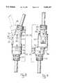
- FIG. 1is an exploded perspective view of the adjustable connector of the invention.
- FIG. 2is an elevational view of the adjustable connector with the lateral adjustment section exploded for illustrative purposes.
- FIG. 3is an elevational view of the adjustable connector with the angular adjustment mechanism exploded for illustrative purposes.
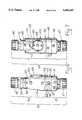
- FIGS. 4-7are side elevational view of the adjustable connector of the invention.
- FIG. 8is an elevational view of the adjustable connector of the invention illustrating the pivotal relationship of the angular adjustment mechanism.
- FIG. 9is an elevational view of the adjustable connector of the invention illustrating the lateral shifting available by use of the lateral adjustment mechanism.
- FIG. 10is an elevational view of the adjustable connector of the invention viewed along its longitudinal axis and illustrating the lateral adjustment capability of the connector.
- FIG. 11is an elevational view of upper component 52.
- the adjustable connector of the inventionis divided into a section discussing the lateral adjustment mechanism and a section discussing the angular adjustment mechanism. It is to be understood that although described as separate components, the two combine to yield a connector which can be angularly and laterally adjustable after connection.
- Lateral adjustment mechanism 12includes a base 14 which includes a generally cylindrical portion 16 defining an interior cavity 18.
- Base 14terminates in an upper surface 19 having an annular flat groove 17 adjacent cavity 18.
- a pair of threaded boresare provided within base 14 in communication with cavity 18 for accommodating set screws 20 such that screws 20 can extend into cavity 18.
- An externally threaded throat 22extends longitudinally from portion 16 of base 14 and defines a cavity 24 shaped as illustrated. Cavity 24 accommodates a spherical slotted connection device 26 and a portion of an external fixation rod (see FIGS. 8 and 9).
- An end cap 27screws onto throat 22 to compress the slotted connection device 26 for clamping engagement with the fixator rod,
- a series of flats 28are formed on base 14 between the throat 22 and portion 16 to provide a surface for connection of a tightening device such as a wrench (not shown).
- Base 14is fixed relative to the fixation rod (FIGS. 8 and 9) after the end cap 27 compresses the connection device 26 onto the fixator rod.
- An intermediate component 30is provided and as is illustrated includes a plate 32 having a circular periphery defining an upper surface 34 and a lower surface 36.
- a generally cylindrical post 38 having a circumference substantially conforming to cavity 18extends integrally from lower surface 36 and includes an annular V-shaped groove 40.
- a dovetail shaped slot 42is formed in plate 32 extending into the plate from upper surface 34 as illustrated.
- a longitudinal groove 35is formed centrally on the bottom wall of the dovetail slot 42.
- a pair of threaded boresare formed in the peripheral side wall of plate 32 and are in communication with slot 42.
- a pair of set screws 44are accommodated by the threaded bores for extension into the dovetail slot 42.
- a slot 45is formed in plate 32 transverse to slot 42 and adjacent one end thereof.
- a screw 46is positioned within slot 42 and includes a head 48 and a collar 50 spaced from the head as illustrated. Collar 50 is accommodated within slot 45 and rotates freely therein about the longitudinal axis of the screw 46.
- Intermediate component 30is configured for connection to base 14. Cylindrical post 38 is seated within cavity 18 of base 14 with the upper surface 19 and lower surface 36 in abutting engagement. Intermediate component 30 is rotatable relative to base 14 about post 38. Intermediate component 30 may be held fixed relative to base 14 by turning screws 20 into their threaded bores such that the pointed end of the screws contact the V-shaped groove of the post in an interference fashion. Groove 17 reduces the surface contact between base 14 and intermediate component 30 thereby reducing the friction between the two components making the rotation of component 30 relative to component 14 easier.
- An upper component 52 for connection between the intermediate component 30 and angle adjustment mechanism 70(described below) is provided and includes a plate 54 having a circular periphery closely matching the periphery of intermediate component 30.
- a dovetail shaped rail 56extends along one surface of plate 54 and is slidably accommodated within the dovetail shaped slot 42 of the intermediate plate 30.
- Rail 56extends a partial distance across the diameter of plate 54 and includes a threaded central longitudinal bore 57 for accommodating the shaft of screw 46 carried by the intermediate plate 30.
- a cylindrical post 58 similar to post 38extends integrally from plate 54 on an opposite side of rail 56.
- Post 58includes an annular V-shaped groove 60.
- Angular adjustment mechanism 70is shown in exploded view in FIGS. 1 and 3 and includes a base 72 which includes a plate 74 having a circular periphery.
- An externally threaded throat 76extends from one side of plate 74 and includes a cavity 78 which is substantially similar to the cavity 24 of base 14 for the accommodation of a clamping device 79 and an end portion of a fixator rod.
- Cap 80screws onto throat 76 for compressing the clamping device about the fixator rod to secure the rod to the angular adjustment mechanism 70.
- a generally cylindrical post 82extends from plate 74 opposite throat 76 and includes a annular V-shaped grove 84.
- a plurality of flats 86are formed about the periphery of plate 74 for accommodation of a tightening device such as a wrench (not shown).
- An intermediate component 90includes a body 92 having a cylindrical end with a cylindrical cavity 94 formed therein.
- An annular groove 91is formed on the upper surface 93 about cavity 94.
- the opposite end of body 92is forked and includes a pair of legs 96 which terminate in an arcuate tapered ends as illustrated.
- a flattened outer surface 97is formed on each leg 96.
- Legs 96are spaced from one another to define an opening therebetween as illustrated in the figures.
- a smooth through bore 100is formed in each leg 96 adjacent its arcuate end.
- a through bore 102is formed through body 92 parallel with through bores 100.
- a pair of threaded boresare formed in the cylindrical end of body 94 in communication with cavity 94 for accommodation of set screws 98.
- a smooth shaft 104is carried within through bores 100 and rotates freely therein.
- Shaft 104includes a central transverse through bore 106 having internal threads. Bore 106 is in alignment with the opening between legs 96
- a lower component 110is provided and includes a pair of spaced legs 112, 113 extending integrally from a circular plate 114 and each having an arcuate periphery and terminating in an arcuate end as illustrated in the figures.
- a threaded boreis formed adjacent the distal ends of legs 112, 113 for accommodating set screws 116 therein.
- a second threaded bore 118is formed in leg 113 as illustrated.
- a smooth throughbore 120is formed in leg 112 in alignment with threaded bore 118.
- Legs 112, 113are spaced so as to accommodate intermediate component 90 therebetween as illustrated.
- a pin 122 having a threaded endis inserted through smooth throughbore 120, throughbore 102 and turned within threaded bore 118 to secure the intermediate component 90 to lower component.
- Intermediate component 90is rotatable relative to lower component 110 about pin 122.
- a plate 124 having a central openingis connected by screws 126 to component 110 and spans legs 112, 113.
- the shaft of screw 128extends through the central opening of plate 124.
- a face plate 125is connected to plate 124 by screws 123 and includes an opening aligned with the central opening of plate 124.
- the head of screw 128is generally round and is rotatably captured between plates 124 and 125.
- the threaded shaft of screw 128is threadibly accommodated within the central transverse opening of shaft 104 such that as screw 128 is rotated, shaft 104 travels along the screw which causes the intermediate component 90 to rotate about pin 122.
- a cavity 130is formed in plate 114 of lower component 110 as illustrated to accommodate the cylindrical component 58 of the lateral adjustment mechanism 12.
- An annular groove 131is formed adjacent cavity 130 on the lower surface of component 110.
- a pair of threaded through boresare formed through plate 114 in communication with cavity 130 for accommodating set screws 132.
- FIG. 9Two basic adjustments are possible using the adjustable connector of the invention, a lateral adjustment as illustrated in FIG. 9 wherein the two fixator rods are laterally offset from one another, and an angular adjustment as illustrated in FIG. 8 wherein the fixator rods are positioned at an angle less than 180 degrees relative to one another.
- the lateral adjustment mechanism 12 and the angular adjustment mechanism 70may be independently rotated about the cylindrical posts so as to enable the user to effect the lateral and angular adjustments in any direction around the central longitudinal axis of the connector as identified in FIGS. 6 through 9.
- FIG. 9illustrates a possible orientation of the upper component 52 relative to intermediate component 30 which can be achieved by rotation of screw 46.
- components 30 and 52may be rotated by the surgeon 360 degrees around the longitudinal axis of the mechanism 10.
- the mechanismprovides lateral adjustment of a pair of fixator rods in any direction with a single adjustment mechanism.
- the rotation freedom of the adjustment mechanism 10 of the inventionis illustrated in FIG. 10.
- the userrotates screw 128 with an appropriate driver instrument (not shown) such as a hex driver. Since the screw head is captured between plates 124 and 125, the screw is laterally static during rotation. However, as screw 128 is rotated, shaft 104 travels along the threaded screw shaft causing intermediate component 90 to rotate about pin 122 as illustrated in FIG. 8. Since intermediate component 90 and lower component 110 are connected to base 72 and the lateral adjustment mechanism 12 by posts 82 and 58 respectively, the intermediate component and the lower component may be rotated 360 degrees on the posts. The ability to rotate these components allows a user to rotate intermediate component 90 in any direction to properly position the attached fixator rods.
- an appropriate driver instrumentsuch as a hex driver. Since the screw head is captured between plates 124 and 125, the screw is laterally static during rotation. However, as screw 128 is rotated, shaft 104 travels along the threaded screw shaft causing intermediate component 90 to rotate about pin 122 as illustrated in FIG. 8. Since intermediate component 90 and lower component 110 are connected to base 72 and the
- the lateral adjustment mechanism 12 and angle adjustment mechanism 70may be rotated independently of one another. If desired, by tightening screws 132 into engagement with post 58, the adjustment mechanism 12 and 70 could be rotated together about posts 38 and 82.
- set screws 20, 44, 132, 116, and 98may be tightened to rigidly secure the component parts of the device 10 in the desired orientation.
Landscapes
- Health & Medical Sciences (AREA)
- Orthopedic Medicine & Surgery (AREA)
- Life Sciences & Earth Sciences (AREA)
- Surgery (AREA)
- Biomedical Technology (AREA)
- Engineering & Computer Science (AREA)
- Nuclear Medicine, Radiotherapy & Molecular Imaging (AREA)
- Heart & Thoracic Surgery (AREA)
- Medical Informatics (AREA)
- Molecular Biology (AREA)
- Animal Behavior & Ethology (AREA)
- General Health & Medical Sciences (AREA)
- Public Health (AREA)
- Veterinary Medicine (AREA)
- Surgical Instruments (AREA)
Abstract
Description
Claims (15)
Priority Applications (5)
| Application Number | Priority Date | Filing Date | Title |
|---|---|---|---|
| US08/016,909US5405347A (en) | 1993-02-12 | 1993-02-12 | Adjustable connector for external fixation rods |
| CA002114759ACA2114759A1 (en) | 1993-02-12 | 1994-02-02 | Adjustable connector for external fixation rods |
| DE69420435TDE69420435D1 (en) | 1993-02-12 | 1994-02-10 | Adjustable connecting element for external fixation rods |
| EP94200354AEP0611007B1 (en) | 1993-02-12 | 1994-02-10 | Adjustable connector for external fixation rods |
| AU55030/94AAU683628B2 (en) | 1993-02-12 | 1994-02-10 | Adjustable connector for external fixation rods |
Applications Claiming Priority (1)
| Application Number | Priority Date | Filing Date | Title |
|---|---|---|---|
| US08/016,909US5405347A (en) | 1993-02-12 | 1993-02-12 | Adjustable connector for external fixation rods |
Publications (1)
| Publication Number | Publication Date |
|---|---|
| US5405347Atrue US5405347A (en) | 1995-04-11 |
Family
ID=21779671
Family Applications (1)
| Application Number | Title | Priority Date | Filing Date |
|---|---|---|---|
| US08/016,909Expired - Fee RelatedUS5405347A (en) | 1993-02-12 | 1993-02-12 | Adjustable connector for external fixation rods |
Country Status (5)
| Country | Link |
|---|---|
| US (1) | US5405347A (en) |
| EP (1) | EP0611007B1 (en) |
| AU (1) | AU683628B2 (en) |
| CA (1) | CA2114759A1 (en) |
| DE (1) | DE69420435D1 (en) |
Cited By (69)
| Publication number | Priority date | Publication date | Assignee | Title |
|---|---|---|---|---|
| US5676664A (en)* | 1995-11-27 | 1997-10-14 | Zimmer, Inc. | Orthopaedic distractor and/or fixator |
| US5683404A (en)* | 1996-06-05 | 1997-11-04 | Metagen, Llc | Clamp and method for its use |
| US5702389A (en)* | 1995-03-01 | 1997-12-30 | Smith & Nephew Richards, Inc. | Orthopaedic fixation device |
| US5728095A (en)* | 1995-03-01 | 1998-03-17 | Smith & Nephew, Inc. | Method of using an orthopaedic fixation device |
| US5738684A (en)* | 1995-05-01 | 1998-04-14 | Keele University | External bone fixator |
| US5971984A (en)* | 1995-03-01 | 1999-10-26 | Smith & Nephew, Inc. | Method of using an orthopaedic fixation device |
| US5997537A (en)* | 1998-05-28 | 1999-12-07 | Electro Biology, Inc. | Ring system for external fixation of bone and related method |
| US6010501A (en)* | 1997-12-15 | 2000-01-04 | Electro-Biology, Inc. | Method and apparatus for external fixation of small bones |
| WO2001056486A1 (en)* | 2000-02-02 | 2001-08-09 | Immedica | Adjustable bone stabilizing frame system |
| US6413258B1 (en) | 1999-08-12 | 2002-07-02 | Osteotech, Inc. | Rod-to-rod coupler |
| US6461358B1 (en)* | 1998-12-31 | 2002-10-08 | Orthofix, S.R.L. | Device for the external fixation of bones fractures, in particular ankle fractures |
| US20030069580A1 (en)* | 2001-10-09 | 2003-04-10 | Langmaid Michael N. | Adjustable fixator |
| US20030149430A1 (en)* | 2002-02-04 | 2003-08-07 | Joseph Ferrante | Devices, systems, and methods for placing and positioning fixation elements in external fixation systems |
| US20030149429A1 (en)* | 2002-02-04 | 2003-08-07 | Joseph Ferrante | External fixation system |
| US6607202B1 (en)* | 1998-05-08 | 2003-08-19 | R. T. Palmer Ltd. | Orthotic walker |
| US20030185621A1 (en)* | 2002-03-27 | 2003-10-02 | Rundle Kenneth P. | Adjustable support apparatus |
| US20030216734A1 (en)* | 2002-05-20 | 2003-11-20 | Citieffe S.R.L. | External fixation system for treating bone fractures |
| US20040116926A1 (en)* | 2000-05-09 | 2004-06-17 | Daniele Venturini | Ring fixator |
| US20040138659A1 (en)* | 2003-01-10 | 2004-07-15 | Ed Austin | External fixation apparatus and method |
| US20040258460A1 (en)* | 2003-06-20 | 2004-12-23 | Taylor Steve B. | Coupler |
| US20050089363A1 (en)* | 2003-10-24 | 2005-04-28 | Curtis Michael J. | Device for offsetting prosthetic components |
| US20050228376A1 (en)* | 2004-03-31 | 2005-10-13 | Boomer Mark C | Adjustable-angle spinal fixation element |
| US20050245939A1 (en)* | 2002-06-14 | 2005-11-03 | Joseph Ferrante | Device and methods for placing external fixation elements |
| US20050261680A1 (en)* | 2001-03-28 | 2005-11-24 | Imperial College Innovations Ltd. | Bone fixated, articulated joint load control device |
| US7116911B2 (en)* | 2000-05-16 | 2006-10-03 | Kiribati Wireless Ventures, Llc | Optical transceiver design and mechanical features |
| US20060229602A1 (en)* | 2005-03-18 | 2006-10-12 | Olsen Ron A | Adjustable splint for osteosynthesis |
| US20060229605A1 (en)* | 2005-03-18 | 2006-10-12 | Olsen Ron A | Adjustable splint for osteosynthesis with incrementing assembly for adjustment in predetermined increments |
| US20070162028A1 (en)* | 2005-12-09 | 2007-07-12 | Jesse Jackson | Cannulated screw |
| US20080275560A1 (en)* | 2007-05-01 | 2008-11-06 | Exploramed Nc4, Inc. | Femoral and tibial base components |
| US20080275559A1 (en)* | 2007-05-01 | 2008-11-06 | Exploramed Nc4, Inc. | Adjustable absorber designs for implantable device |
| US20080275558A1 (en)* | 2007-05-01 | 2008-11-06 | Exploramed Nc4, Inc. | Extra-articular implantable mechanical energy absorbing systems and implantation method |
| US20080275555A1 (en)* | 2007-05-01 | 2008-11-06 | Exploramed Nc4, Inc. | Extra-Articular Implantable Mechanical Energy Absorbing Systems |
| US20080306553A1 (en)* | 2007-06-05 | 2008-12-11 | Spartek Medical, Inc. | Bone anchor with a compressor element for receiving a rod for a dynamic stabilization and motion preservation spinal implantation system and method |
| US20090189038A1 (en)* | 2008-01-30 | 2009-07-30 | James Timothy R | Apparatus and method for mounting a bimini top |
| USRE40914E1 (en) | 1997-10-20 | 2009-09-08 | Smith & Nephew, Inc. | Orthopaedic fixation plate |
| US20090276052A1 (en)* | 2008-04-30 | 2009-11-05 | Exploramed Nc4, Inc. | Ball and socket assembly |
| US20100087819A1 (en)* | 2008-10-07 | 2010-04-08 | Extraortho, Inc. | Forward Kinematic Solution for a Hexapod Manipulator and Method of Use |
| US20100137996A1 (en)* | 2007-05-01 | 2010-06-03 | Moximed, Inc. | Femoral and tibial base components |
| US20110093080A1 (en)* | 2009-10-20 | 2011-04-21 | Slone Clinton N | Extra-articular implantable mechanical energy absorbing assemblies having two deflecting members and methods |
| US20110202138A1 (en)* | 2009-08-27 | 2011-08-18 | The Foundry Llc | Method and Apparatus for Force Redistribution in Articular Joints |
| US8123805B2 (en) | 2007-05-01 | 2012-02-28 | Moximed, Inc. | Adjustable absorber designs for implantable device |
| US20130047813A1 (en)* | 2011-08-22 | 2013-02-28 | Sean T. Kehoe | Draw stud connector |
| US8523948B2 (en) | 2009-10-20 | 2013-09-03 | Moximed, Inc. | Extra-articular implantable mechanical energy absorbing assemblies having a tension member, and methods |
| US20140018930A1 (en)* | 2011-03-04 | 2014-01-16 | Swemac Innovation Ab | Prosthesis for arthrodhesis |
| US8709090B2 (en) | 2007-05-01 | 2014-04-29 | Moximed, Inc. | Adjustable absorber designs for implantable device |
| US8758343B2 (en) | 2005-04-27 | 2014-06-24 | DePuy Synthes Products, LLC | Bone fixation apparatus |
| US8845724B2 (en) | 2009-08-27 | 2014-09-30 | Cotera, Inc. | Method and apparatus for altering biomechanics of the articular joints |
| US8894714B2 (en) | 2007-05-01 | 2014-11-25 | Moximed, Inc. | Unlinked implantable knee unloading device |
| US9044270B2 (en) | 2011-03-29 | 2015-06-02 | Moximed, Inc. | Apparatus for controlling a load on a hip joint |
| US9393711B2 (en) | 2011-04-11 | 2016-07-19 | Milwaukee Electric Tool Corporation | Hand-held knockout punch driver |
| US9398957B2 (en) | 2007-05-01 | 2016-07-26 | Moximed, Inc. | Femoral and tibial bases |
| US9468466B1 (en) | 2012-08-24 | 2016-10-18 | Cotera, Inc. | Method and apparatus for altering biomechanics of the spine |
| CN106102616A (en)* | 2014-01-24 | 2016-11-09 | 奥瑟菲克斯有限公司 | Elongate pin for external fixer |
| US9668868B2 (en) | 2009-08-27 | 2017-06-06 | Cotera, Inc. | Apparatus and methods for treatment of patellofemoral conditions |
| US9770272B2 (en) | 2012-12-12 | 2017-09-26 | Wright Medical Technology, Inc. | Orthopedic compression/distraction device |
| US9827011B2 (en)* | 2013-03-15 | 2017-11-28 | Biomet Manufacturing, Llc | Polyaxial pivot housing for external fixation system |
| US9861408B2 (en) | 2009-08-27 | 2018-01-09 | The Foundry, Llc | Method and apparatus for treating canine cruciate ligament disease |
| US9907645B2 (en) | 2007-05-01 | 2018-03-06 | Moximed, Inc. | Adjustable absorber designs for implantable device |
| US9962188B2 (en) | 2013-10-29 | 2018-05-08 | Cardinal Health 247. Inc. | External fixation system and methods of use |
| US10004538B2 (en)* | 2016-04-27 | 2018-06-26 | Warsaw Orthopedic, Inc. | Surgical instrument and method |
| US20190071153A1 (en)* | 2017-09-05 | 2019-03-07 | Railblaza Limited | Extender for holding accessories |
| US10349980B2 (en) | 2009-08-27 | 2019-07-16 | The Foundry, Llc | Method and apparatus for altering biomechanics of the shoulder |
| US10368918B2 (en) | 2011-03-01 | 2019-08-06 | Nuvasive, Inc. | Posterior cervical fixation system |
| US10610261B2 (en) | 2016-02-12 | 2020-04-07 | Nuvasive, Inc. | Post-operatively adjustable angled rod |
| US20210186562A1 (en)* | 2018-09-05 | 2021-06-24 | Amdt Holdings, Inc. | Adjustable rail apparatus for external fixation systems |
| USD953146S1 (en)* | 2020-11-18 | 2022-05-31 | Western Technology, Inc. | Cogged mounting knuckle assembly |
| US11378114B2 (en)* | 2018-10-09 | 2022-07-05 | Taylor Made Group, Llc | Quick disconnect mount |
| US11446063B2 (en) | 2016-02-12 | 2022-09-20 | Nuvasive, Inc. | Post-operatively adjustable angled rod |
| US11460062B2 (en)* | 2020-11-18 | 2022-10-04 | Western Technology, Inc. | Lockable relative rotation device |
Families Citing this family (11)
| Publication number | Priority date | Publication date | Assignee | Title |
|---|---|---|---|---|
| FR2725613B1 (en)* | 1994-10-12 | 1997-03-14 | Hardy Jean Marie | EXTERNAL FIXER APPLICABLE IN ORTHOPEDICS AND TRAUMATOLOGY |
| DE29619711U1 (en)* | 1996-11-13 | 1998-03-12 | Synthes AG Chur, Chur, Graubünden | Device for repositioning bone fracture fragments |
| US8858555B2 (en) | 2009-10-05 | 2014-10-14 | Stryker Trauma Sa | Dynamic external fixator and methods for use |
| US8945128B2 (en) | 2010-08-11 | 2015-02-03 | Stryker Trauma Sa | External fixator system |
| US11141196B2 (en) | 2010-08-11 | 2021-10-12 | Stryker European Operations Holdings Llc | External fixator system |
| EP2417924B1 (en) | 2010-08-11 | 2015-07-01 | Stryker Trauma SA | External fixator system |
| US9101398B2 (en) | 2012-08-23 | 2015-08-11 | Stryker Trauma Sa | Bone transport external fixation frame |
| US10010350B2 (en) | 2016-06-14 | 2018-07-03 | Stryker European Holdings I, Llc | Gear mechanisms for fixation frame struts |
| US10874433B2 (en) | 2017-01-30 | 2020-12-29 | Stryker European Holdings I, Llc | Strut attachments for external fixation frame |
| CN213549184U (en)* | 2020-10-09 | 2021-06-29 | 威海泰美瑞金属制品有限公司 | Fishing rod handle device capable of rotatably adjusting bending and straightening |
| CN118697396B (en)* | 2024-07-23 | 2025-04-11 | 中国人民解放军总医院第一医学中心 | Scalp traction surgical device |
Citations (32)
| Publication number | Priority date | Publication date | Assignee | Title |
|---|---|---|---|---|
| US2333033A (en)* | 1943-06-11 | 1943-10-26 | Leslie E Mraz | Bone splint |
| US2911178A (en)* | 1958-05-16 | 1959-11-03 | Joffe Leon | Micro-swing holder for dial indicator |
| US3976061A (en)* | 1974-07-22 | 1976-08-24 | Mstislav Vasilievich Volkov | Apparatus for surgical treatment of bones and joints |
| US3977397A (en)* | 1974-11-27 | 1976-08-31 | Kalnberz Viktor Konstantinovic | Surgical compression-distraction instrument |
| US4033340A (en)* | 1973-12-14 | 1977-07-05 | Kalnberz Viktor Konstantinovic | Surgical compression-distraction instrument |
| US4185623A (en)* | 1978-07-18 | 1980-01-29 | Oganesian Oganes V | Apparatus for restoration of hip joint mobility |
| US4312336A (en)* | 1978-11-10 | 1982-01-26 | Orthofix S.R.1. | External axial fixation unit |
| US4365624A (en)* | 1979-01-16 | 1982-12-28 | Jaquet Orthopedie Sa | External bone-anchoring element |
| FR2517535A1 (en)* | 1981-12-09 | 1983-06-10 | Zbikowski Juan | FUNCTIONAL IMMOBILIZATION DEVICE FOR OSTEO-SYNTHESIS USING EXTERNAL FIXATORS |
| US4502473A (en)* | 1981-08-06 | 1985-03-05 | National Research Development Corp. | Apparatus for external fixation of bone fractures |
| US4615338A (en)* | 1985-09-18 | 1986-10-07 | Kurgansky Nauchno-Issledovatelsky Institut Experimentalnoi I Klinicheskoi Ortopedii I Travmatologii | Automatic compression-distraction apparatus |
| US4621627A (en)* | 1984-12-18 | 1986-11-11 | Orthofix S.R.L. | External axial fixation device |
| US4714076A (en)* | 1984-01-19 | 1987-12-22 | Synthes | Device for the setting of bone segments |
| EP0261252A1 (en)* | 1986-09-15 | 1988-03-30 | Agee, John Milton | Colles' fracture splint |
| US4768524A (en)* | 1986-02-28 | 1988-09-06 | Hardy Jean Marie | Device for immobilizing a bone structure, especially intended for orthopedic use |
| US4784125A (en)* | 1985-01-24 | 1988-11-15 | Jaquet Orthopedie, S. A. | Arcuate element and external fixation device containing same for osteosynthesis and osteoplasty |
| US4823781A (en)* | 1987-07-02 | 1989-04-25 | Buchanan William J | Method and apparatus for percutaneous fracture reduction and fixation |
| US4923458A (en)* | 1986-04-17 | 1990-05-08 | Ace Medical Company | Surgical fixation pin tension adjuster |
| US4936843A (en)* | 1989-02-16 | 1990-06-26 | Ace Orthopedic Manufacturing | Kirschner wire clamp and tensioner |
| US4973331A (en)* | 1989-03-08 | 1990-11-27 | Autogenesis Corporation | Automatic compression-distraction-torsion method and apparatus |
| US4988349A (en)* | 1987-01-21 | 1991-01-29 | Orthofix S.R.L. | Device for osteosynthesis |
| EP0420813A1 (en)* | 1989-09-27 | 1991-04-03 | Jaquet Orthopedie S.A. | Device for relative motion and locking of two articulated parts |
| US5019077A (en)* | 1989-03-17 | 1991-05-28 | Orthofix S.R.L. | External splint |
| US5026372A (en)* | 1987-11-05 | 1991-06-25 | Robert Sturtzkopf | Fixation device for the external adjusting of bone fragments |
| US5041112A (en)* | 1989-11-30 | 1991-08-20 | Citieffe S.R.L. | External splint for the treatment of fractures of the long bones of limbs |
| US5062844A (en)* | 1990-09-07 | 1991-11-05 | Smith & Nephew Richards Inc. | Method and apparatus for the fixation of bone fractures, limb lengthening and the correction of deformities |
| EP0460944A1 (en)* | 1990-06-08 | 1991-12-11 | SMITH & NEPHEW RICHARDS, INC. | Dynamic elbow support |
| US5074866A (en)* | 1990-10-16 | 1991-12-24 | Smith & Nephew Richards Inc. | Translation/rotation device for external bone fixation system |
| WO1992002184A1 (en)* | 1990-08-03 | 1992-02-20 | Ascanio Campopiano | Orthopaedic manipulator for reduction and external fixation |
| US5112331A (en)* | 1989-06-15 | 1992-05-12 | Vel Miletich | Orthopedic pins for external fixator |
| GB2250682A (en)* | 1990-12-13 | 1992-06-17 | Weisheng Liu | Universal external fixation device for setting fractured long bone diaphysis |
| US5152280A (en)* | 1989-01-04 | 1992-10-06 | Confida S.A.S | Bone support device |
Family Cites Families (1)
| Publication number | Priority date | Publication date | Assignee | Title |
|---|---|---|---|---|
| US2976061A (en)* | 1959-10-02 | 1961-03-21 | Embree Clifford Albert | Hitch |
- 1993
- 1993-02-12USUS08/016,909patent/US5405347A/ennot_activeExpired - Fee Related
- 1994
- 1994-02-02CACA002114759Apatent/CA2114759A1/ennot_activeAbandoned
- 1994-02-10EPEP94200354Apatent/EP0611007B1/ennot_activeExpired - Lifetime
- 1994-02-10DEDE69420435Tpatent/DE69420435D1/ennot_activeExpired - Lifetime
- 1994-02-10AUAU55030/94Apatent/AU683628B2/ennot_activeCeased
Patent Citations (35)
| Publication number | Priority date | Publication date | Assignee | Title |
|---|---|---|---|---|
| US2333033A (en)* | 1943-06-11 | 1943-10-26 | Leslie E Mraz | Bone splint |
| US2911178A (en)* | 1958-05-16 | 1959-11-03 | Joffe Leon | Micro-swing holder for dial indicator |
| US4033340A (en)* | 1973-12-14 | 1977-07-05 | Kalnberz Viktor Konstantinovic | Surgical compression-distraction instrument |
| US3976061A (en)* | 1974-07-22 | 1976-08-24 | Mstislav Vasilievich Volkov | Apparatus for surgical treatment of bones and joints |
| US3977397A (en)* | 1974-11-27 | 1976-08-31 | Kalnberz Viktor Konstantinovic | Surgical compression-distraction instrument |
| US4185623A (en)* | 1978-07-18 | 1980-01-29 | Oganesian Oganes V | Apparatus for restoration of hip joint mobility |
| US4312336A (en)* | 1978-11-10 | 1982-01-26 | Orthofix S.R.1. | External axial fixation unit |
| US4365624A (en)* | 1979-01-16 | 1982-12-28 | Jaquet Orthopedie Sa | External bone-anchoring element |
| US4502473A (en)* | 1981-08-06 | 1985-03-05 | National Research Development Corp. | Apparatus for external fixation of bone fractures |
| FR2517535A1 (en)* | 1981-12-09 | 1983-06-10 | Zbikowski Juan | FUNCTIONAL IMMOBILIZATION DEVICE FOR OSTEO-SYNTHESIS USING EXTERNAL FIXATORS |
| US4714076A (en)* | 1984-01-19 | 1987-12-22 | Synthes | Device for the setting of bone segments |
| US4621627A (en)* | 1984-12-18 | 1986-11-11 | Orthofix S.R.L. | External axial fixation device |
| US4784125A (en)* | 1985-01-24 | 1988-11-15 | Jaquet Orthopedie, S. A. | Arcuate element and external fixation device containing same for osteosynthesis and osteoplasty |
| US5095919A (en)* | 1985-01-24 | 1992-03-17 | Jaquet Orthopedie S.A. | Arcuate element and external fixation device |
| US4615338A (en)* | 1985-09-18 | 1986-10-07 | Kurgansky Nauchno-Issledovatelsky Institut Experimentalnoi I Klinicheskoi Ortopedii I Travmatologii | Automatic compression-distraction apparatus |
| US4768524A (en)* | 1986-02-28 | 1988-09-06 | Hardy Jean Marie | Device for immobilizing a bone structure, especially intended for orthopedic use |
| US4923458A (en)* | 1986-04-17 | 1990-05-08 | Ace Medical Company | Surgical fixation pin tension adjuster |
| EP0261252A1 (en)* | 1986-09-15 | 1988-03-30 | Agee, John Milton | Colles' fracture splint |
| US4988349A (en)* | 1987-01-21 | 1991-01-29 | Orthofix S.R.L. | Device for osteosynthesis |
| US4823781A (en)* | 1987-07-02 | 1989-04-25 | Buchanan William J | Method and apparatus for percutaneous fracture reduction and fixation |
| US5026372A (en)* | 1987-11-05 | 1991-06-25 | Robert Sturtzkopf | Fixation device for the external adjusting of bone fragments |
| US5152280A (en)* | 1989-01-04 | 1992-10-06 | Confida S.A.S | Bone support device |
| US4936843A (en)* | 1989-02-16 | 1990-06-26 | Ace Orthopedic Manufacturing | Kirschner wire clamp and tensioner |
| US4973331A (en)* | 1989-03-08 | 1990-11-27 | Autogenesis Corporation | Automatic compression-distraction-torsion method and apparatus |
| US5019077A (en)* | 1989-03-17 | 1991-05-28 | Orthofix S.R.L. | External splint |
| US5112331A (en)* | 1989-06-15 | 1992-05-12 | Vel Miletich | Orthopedic pins for external fixator |
| EP0420813A1 (en)* | 1989-09-27 | 1991-04-03 | Jaquet Orthopedie S.A. | Device for relative motion and locking of two articulated parts |
| US5167661A (en)* | 1989-09-27 | 1992-12-01 | Jaquet Orthopedie S.A. | Device for articulation and relative locking of two pieces |
| US5041112A (en)* | 1989-11-30 | 1991-08-20 | Citieffe S.R.L. | External splint for the treatment of fractures of the long bones of limbs |
| EP0460944A1 (en)* | 1990-06-08 | 1991-12-11 | SMITH & NEPHEW RICHARDS, INC. | Dynamic elbow support |
| WO1992002184A1 (en)* | 1990-08-03 | 1992-02-20 | Ascanio Campopiano | Orthopaedic manipulator for reduction and external fixation |
| US5062844A (en)* | 1990-09-07 | 1991-11-05 | Smith & Nephew Richards Inc. | Method and apparatus for the fixation of bone fractures, limb lengthening and the correction of deformities |
| US5074866A (en)* | 1990-10-16 | 1991-12-24 | Smith & Nephew Richards Inc. | Translation/rotation device for external bone fixation system |
| EP0481697A1 (en)* | 1990-10-16 | 1992-04-22 | SMITH & NEPHEW RICHARDS, INC. | Translation/rotation device for external bone fixation system |
| GB2250682A (en)* | 1990-12-13 | 1992-06-17 | Weisheng Liu | Universal external fixation device for setting fractured long bone diaphysis |
Cited By (177)
| Publication number | Priority date | Publication date | Assignee | Title |
|---|---|---|---|---|
| US5702389A (en)* | 1995-03-01 | 1997-12-30 | Smith & Nephew Richards, Inc. | Orthopaedic fixation device |
| US5728095A (en)* | 1995-03-01 | 1998-03-17 | Smith & Nephew, Inc. | Method of using an orthopaedic fixation device |
| US5971984A (en)* | 1995-03-01 | 1999-10-26 | Smith & Nephew, Inc. | Method of using an orthopaedic fixation device |
| US5738684A (en)* | 1995-05-01 | 1998-04-14 | Keele University | External bone fixator |
| US5676664A (en)* | 1995-11-27 | 1997-10-14 | Zimmer, Inc. | Orthopaedic distractor and/or fixator |
| US5683404A (en)* | 1996-06-05 | 1997-11-04 | Metagen, Llc | Clamp and method for its use |
| USRE40914E1 (en) | 1997-10-20 | 2009-09-08 | Smith & Nephew, Inc. | Orthopaedic fixation plate |
| US6010501A (en)* | 1997-12-15 | 2000-01-04 | Electro-Biology, Inc. | Method and apparatus for external fixation of small bones |
| US6607202B1 (en)* | 1998-05-08 | 2003-08-19 | R. T. Palmer Ltd. | Orthotic walker |
| US5997537A (en)* | 1998-05-28 | 1999-12-07 | Electro Biology, Inc. | Ring system for external fixation of bone and related method |
| US6461358B1 (en)* | 1998-12-31 | 2002-10-08 | Orthofix, S.R.L. | Device for the external fixation of bones fractures, in particular ankle fractures |
| US6413258B1 (en) | 1999-08-12 | 2002-07-02 | Osteotech, Inc. | Rod-to-rod coupler |
| WO2001056486A1 (en)* | 2000-02-02 | 2001-08-09 | Immedica | Adjustable bone stabilizing frame system |
| US8696668B2 (en) | 2000-02-02 | 2014-04-15 | Zimmer, Inc. | Adjustable bone stabilizing frame system |
| US7226449B2 (en)* | 2000-05-09 | 2007-06-05 | Orthofix S.R.L. | Ring fixator |
| US20040116926A1 (en)* | 2000-05-09 | 2004-06-17 | Daniele Venturini | Ring fixator |
| US20070116471A1 (en)* | 2000-05-16 | 2007-05-24 | Scott Harris Bloom | Optical transceiver design and mechanical features |
| US7116911B2 (en)* | 2000-05-16 | 2006-10-03 | Kiribati Wireless Ventures, Llc | Optical transceiver design and mechanical features |
| US7536106B2 (en) | 2000-05-16 | 2009-05-19 | Kiribati Wireless Ventures, Llc | Optical transceiver design and mechanical features |
| US9943336B2 (en) | 2001-03-28 | 2018-04-17 | Moximed, Inc. | Bone fixated, articulated joint load control device |
| US7763020B2 (en)* | 2001-03-28 | 2010-07-27 | Moximed, Inc. | Bone fixated, articulated joint load control device |
| US20090248026A1 (en)* | 2001-03-28 | 2009-10-01 | Moximed, Inc. | Bone fixated, articulated joint load control device |
| US9610103B2 (en) | 2001-03-28 | 2017-04-04 | Moximed, Inc. | Bone fixated, articulated joint load control device |
| US20050261680A1 (en)* | 2001-03-28 | 2005-11-24 | Imperial College Innovations Ltd. | Bone fixated, articulated joint load control device |
| US20100145336A1 (en)* | 2001-03-28 | 2010-06-10 | Moximed, Inc. | Bone fixated, articulated joint load control device |
| US8382757B1 (en)* | 2001-10-09 | 2013-02-26 | Synthes Usa, Llc | Adjustable fixator |
| US20030069580A1 (en)* | 2001-10-09 | 2003-04-10 | Langmaid Michael N. | Adjustable fixator |
| US7261713B2 (en) | 2001-10-09 | 2007-08-28 | Synthes (Usa) | Adjustable fixator |
| US7887537B2 (en) | 2002-02-04 | 2011-02-15 | Smith & Nephew, Inc. | External fixation system |
| US7048735B2 (en) | 2002-02-04 | 2006-05-23 | Smith & Nephew | External fixation system |
| US7004943B2 (en) | 2002-02-04 | 2006-02-28 | Smith & Nephew, Inc. | Devices, systems, and methods for placing and positioning fixation elements in external fixation systems |
| US20030149429A1 (en)* | 2002-02-04 | 2003-08-07 | Joseph Ferrante | External fixation system |
| US20030149430A1 (en)* | 2002-02-04 | 2003-08-07 | Joseph Ferrante | Devices, systems, and methods for placing and positioning fixation elements in external fixation systems |
| US20050119656A1 (en)* | 2002-02-04 | 2005-06-02 | Joseph Ferrante | External fixation system |
| US20030185621A1 (en)* | 2002-03-27 | 2003-10-02 | Rundle Kenneth P. | Adjustable support apparatus |
| US6921226B2 (en) | 2002-03-27 | 2005-07-26 | Biomec, Inc. | Adjustable support apparatus |
| US20030216734A1 (en)* | 2002-05-20 | 2003-11-20 | Citieffe S.R.L. | External fixation system for treating bone fractures |
| US7758582B2 (en) | 2002-06-14 | 2010-07-20 | Smith & Nephew, Inc. | Device and methods for placing external fixation elements |
| US20050245939A1 (en)* | 2002-06-14 | 2005-11-03 | Joseph Ferrante | Device and methods for placing external fixation elements |
| US7608074B2 (en) | 2003-01-10 | 2009-10-27 | Smith & Nephew, Inc. | External fixation apparatus and method |
| WO2004062514A1 (en)* | 2003-01-10 | 2004-07-29 | Smith & Nephew, Inc. | External fixation apparatus |
| US20040138659A1 (en)* | 2003-01-10 | 2004-07-15 | Ed Austin | External fixation apparatus and method |
| US20070255280A1 (en)* | 2003-01-10 | 2007-11-01 | Smith & Nephew, Inc. | External fixation apparatus and method |
| US8382755B2 (en)* | 2003-01-10 | 2013-02-26 | Smith & Nephew, Inc. | External fixation apparatus and method |
| US7334956B2 (en)* | 2003-06-20 | 2008-02-26 | Taylor Steve B | Coupler |
| US20040258460A1 (en)* | 2003-06-20 | 2004-12-23 | Taylor Steve B. | Coupler |
| US20050089363A1 (en)* | 2003-10-24 | 2005-04-28 | Curtis Michael J. | Device for offsetting prosthetic components |
| US7090700B2 (en)* | 2003-10-24 | 2006-08-15 | American Prosthetic Components, Inc. | Device for offsetting prosthetic components |
| US8870918B2 (en) | 2004-03-31 | 2014-10-28 | Depuy Spine Sarl | Adjustable-angle spinal fixation element |
| US8795339B2 (en) | 2004-03-31 | 2014-08-05 | Depuy Spine Sarl | Adjustable-angle spinal fixation element |
| US10722275B2 (en) | 2004-03-31 | 2020-07-28 | Medos International Sàrl | Adjustable-angle spinal fixation element |
| US20050228376A1 (en)* | 2004-03-31 | 2005-10-13 | Boomer Mark C | Adjustable-angle spinal fixation element |
| US20080033434A1 (en)* | 2004-03-31 | 2008-02-07 | Depuy Spine, Inc. | Adjustable-angle spinal fixation element |
| US8109974B2 (en) | 2004-03-31 | 2012-02-07 | Depuy Spine Sarl | Adjustable-angle spinal fixation element |
| US7909852B2 (en)* | 2004-03-31 | 2011-03-22 | Depuy Spine Sarl | Adjustable-angle spinal fixation element |
| US9155565B2 (en) | 2004-03-31 | 2015-10-13 | Medos International Sarl | Adjustable-angle spinal fixation element |
| US11717330B2 (en) | 2004-03-31 | 2023-08-08 | Medos International Sarl | Adjustable-angle spinal fixation element |
| US20110098749A1 (en)* | 2004-03-31 | 2011-04-28 | Depuy Spine, Inc. | Adjustable-angle spinal fixation element |
| US9974572B2 (en) | 2004-03-31 | 2018-05-22 | Medos International Sarl | Adjustable-angle spinal fixation element |
| US9498258B2 (en) | 2004-03-31 | 2016-11-22 | Medos International Sarl | Adjustable-angle spinal fixation element |
| US7575575B2 (en) | 2005-03-18 | 2009-08-18 | Ron Anthon Olsen | Adjustable splint for osteosynthesis with modular components |
| US20060229605A1 (en)* | 2005-03-18 | 2006-10-12 | Olsen Ron A | Adjustable splint for osteosynthesis with incrementing assembly for adjustment in predetermined increments |
| US7588571B2 (en) | 2005-03-18 | 2009-09-15 | Ron Anthon Olsen | Adjustable splint for osteosynthesis with modular joint |
| US7507240B2 (en) | 2005-03-18 | 2009-03-24 | Ron Anthon Olsen | Adjustable splint for osteosynthesis |
| US20060229602A1 (en)* | 2005-03-18 | 2006-10-12 | Olsen Ron A | Adjustable splint for osteosynthesis |
| US20060229604A1 (en)* | 2005-03-18 | 2006-10-12 | Olsen Ron A | Adjustable splint for osteosynthesis with modular components |
| US8758343B2 (en) | 2005-04-27 | 2014-06-24 | DePuy Synthes Products, LLC | Bone fixation apparatus |
| US20070162028A1 (en)* | 2005-12-09 | 2007-07-12 | Jesse Jackson | Cannulated screw |
| US7731738B2 (en) | 2005-12-09 | 2010-06-08 | Orthopro, Llc | Cannulated screw |
| US20110137415A1 (en)* | 2007-05-01 | 2011-06-09 | Moximed, Inc. | Extra-Articular Implantable Mechanical Energy Absorbing Systems and Implantation Method |
| US10010421B2 (en) | 2007-05-01 | 2018-07-03 | Moximed, Inc. | Extra-articular implantable mechanical energy absorbing systems |
| US20100114322A1 (en)* | 2007-05-01 | 2010-05-06 | Moximed, Inc. | Extra-Articular Implantable Mechanical Energy Absorbing Systems and Implantation Method |
| US20100106247A1 (en)* | 2007-05-01 | 2010-04-29 | Moximed, Inc. | Extra-Articular Implantable Mechanical Energy Absorbing Systems |
| US20100106248A1 (en)* | 2007-05-01 | 2010-04-29 | Moximed, Inc. | Extra-Articular Implantable Mechanical Energy Absorbing Systems |
| US20110060422A1 (en)* | 2007-05-01 | 2011-03-10 | Moximed, Inc. | Adjustable Absorber Designs for Implantable Device |
| US20080275560A1 (en)* | 2007-05-01 | 2008-11-06 | Exploramed Nc4, Inc. | Femoral and tibial base components |
| US7678147B2 (en) | 2007-05-01 | 2010-03-16 | Moximed, Inc. | Extra-articular implantable mechanical energy absorbing systems and implantation method |
| US7655041B2 (en) | 2007-05-01 | 2010-02-02 | Moximed, Inc. | Extra-articular implantable mechanical energy absorbing systems and implantation method |
| US9655648B2 (en) | 2007-05-01 | 2017-05-23 | Moximed, Inc. | Femoral and tibial base components |
| US11389298B2 (en) | 2007-05-01 | 2022-07-19 | Moximed, Inc. | Extra-articular implantable mechanical energy absorbing systems |
| US8088166B2 (en) | 2007-05-01 | 2012-01-03 | Moximed, Inc. | Adjustable absorber designs for implantable device |
| US8100967B2 (en) | 2007-05-01 | 2012-01-24 | Moximed, Inc. | Adjustable absorber designs for implantable device |
| US9700419B2 (en) | 2007-05-01 | 2017-07-11 | Moximed, Inc. | Extra-articular implantable mechanical energy absorbing systems and implantation method |
| US8123805B2 (en) | 2007-05-01 | 2012-02-28 | Moximed, Inc. | Adjustable absorber designs for implantable device |
| US7611540B2 (en) | 2007-05-01 | 2009-11-03 | Moximed, Inc. | Extra-articular implantable mechanical energy absorbing systems and implantation method |
| US9814579B2 (en) | 2007-05-01 | 2017-11-14 | Moximed, Inc. | Unlinked implantable knee unloading device |
| US10736746B2 (en) | 2007-05-01 | 2020-08-11 | Moximed, Inc. | Extra-articular implantable mechanical energy absorbing systems |
| US8409281B2 (en) | 2007-05-01 | 2013-04-02 | Moximed, Inc. | Adjustable absorber designs for implantable device |
| US9398957B2 (en) | 2007-05-01 | 2016-07-26 | Moximed, Inc. | Femoral and tibial bases |
| US20080275556A1 (en)* | 2007-05-01 | 2008-11-06 | Exploramed Nc4, Inc. | Adjustable absorber designs for implantable device |
| US9907645B2 (en) | 2007-05-01 | 2018-03-06 | Moximed, Inc. | Adjustable absorber designs for implantable device |
| US10639161B2 (en) | 2007-05-01 | 2020-05-05 | Moximed, Inc. | Extra-articular implantable load sharing systems |
| US10596007B2 (en) | 2007-05-01 | 2020-03-24 | Moximed, Inc. | Extra-articular implantable mechanical energy absorbing systems and implantation method |
| US20080275567A1 (en)* | 2007-05-01 | 2008-11-06 | Exploramed Nc4, Inc. | Extra-Articular Implantable Mechanical Energy Absorbing Systems |
| US8709090B2 (en) | 2007-05-01 | 2014-04-29 | Moximed, Inc. | Adjustable absorber designs for implantable device |
| US20080275555A1 (en)* | 2007-05-01 | 2008-11-06 | Exploramed Nc4, Inc. | Extra-Articular Implantable Mechanical Energy Absorbing Systems |
| US20080275557A1 (en)* | 2007-05-01 | 2008-11-06 | Exploramed Nc4, Inc. | Adjustable absorber designs for implantable device |
| US8801795B2 (en) | 2007-05-01 | 2014-08-12 | Moximed, Inc. | Extra-articular implantable mechanical energy absorbing systems |
| US10383736B2 (en) | 2007-05-01 | 2019-08-20 | Moximed, Inc. | Femoral and tibial base components |
| US20080275565A1 (en)* | 2007-05-01 | 2008-11-06 | Exploramed Nc4, Inc. | Adjustable absorber designs for implantable device |
| US8894714B2 (en) | 2007-05-01 | 2014-11-25 | Moximed, Inc. | Unlinked implantable knee unloading device |
| US9005298B2 (en) | 2007-05-01 | 2015-04-14 | Moximed, Inc. | Extra-articular implantable mechanical energy absorbing systems |
| US20080275559A1 (en)* | 2007-05-01 | 2008-11-06 | Exploramed Nc4, Inc. | Adjustable absorber designs for implantable device |
| US10327816B2 (en) | 2007-05-01 | 2019-06-25 | Moximed, Inc. | Adjustable absorber designs for implantable device |
| US10070964B2 (en) | 2007-05-01 | 2018-09-11 | Moximed, Inc. | Extra-articular implantable mechanical energy absorbing systems and implantation method |
| US10022154B2 (en) | 2007-05-01 | 2018-07-17 | Moximed, Inc. | Femoral and tibial base components |
| US20100137996A1 (en)* | 2007-05-01 | 2010-06-03 | Moximed, Inc. | Femoral and tibial base components |
| US9125746B2 (en) | 2007-05-01 | 2015-09-08 | Moximed, Inc. | Methods of implanting extra-articular implantable mechanical energy absorbing systems |
| US20080275561A1 (en)* | 2007-05-01 | 2008-11-06 | Exploramed Nc4, Inc. | Extra-articular implantable mechanical energy absorbing systems and implantation method |
| US20080275558A1 (en)* | 2007-05-01 | 2008-11-06 | Exploramed Nc4, Inc. | Extra-articular implantable mechanical energy absorbing systems and implantation method |
| US20080306553A1 (en)* | 2007-06-05 | 2008-12-11 | Spartek Medical, Inc. | Bone anchor with a compressor element for receiving a rod for a dynamic stabilization and motion preservation spinal implantation system and method |
| US7635380B2 (en)* | 2007-06-05 | 2009-12-22 | Spartek Medical, Inc. | Bone anchor with a compressor element for receiving a rod for a dynamic stabilization and motion preservation spinal implantation system and method |
| US8616511B2 (en) | 2008-01-30 | 2013-12-31 | Dowco, Inc. | Apparatus and method for mounting a bimini top |
| US20090189038A1 (en)* | 2008-01-30 | 2009-07-30 | James Timothy R | Apparatus and method for mounting a bimini top |
| US9168065B2 (en) | 2008-04-30 | 2015-10-27 | Moximed, Inc. | Ball and socket assembly |
| US10363139B2 (en) | 2008-04-30 | 2019-07-30 | Moximed, Inc. | Ball and socket assembly |
| US20090276052A1 (en)* | 2008-04-30 | 2009-11-05 | Exploramed Nc4, Inc. | Ball and socket assembly |
| US20100087819A1 (en)* | 2008-10-07 | 2010-04-08 | Extraortho, Inc. | Forward Kinematic Solution for a Hexapod Manipulator and Method of Use |
| US8597362B2 (en) | 2009-08-27 | 2013-12-03 | Cotera, Inc. | Method and apparatus for force redistribution in articular joints |
| US9931136B2 (en) | 2009-08-27 | 2018-04-03 | The Foundry, Llc | Method and apparatus for altering biomechanics of articular joints |
| US11730519B2 (en) | 2009-08-27 | 2023-08-22 | The Foundry, Llc | Method and apparatus for force redistribution in articular joints |
| US9668868B2 (en) | 2009-08-27 | 2017-06-06 | Cotera, Inc. | Apparatus and methods for treatment of patellofemoral conditions |
| US9114016B2 (en) | 2009-08-27 | 2015-08-25 | Cotera, Inc. | Method and apparatus for altering biomechanics of the articular joints |
| US9278004B2 (en) | 2009-08-27 | 2016-03-08 | Cotera, Inc. | Method and apparatus for altering biomechanics of the articular joints |
| US11517360B2 (en) | 2009-08-27 | 2022-12-06 | The Foundry, Llc | Method and apparatus for treating canine cruciate ligament disease |
| US10695094B2 (en) | 2009-08-27 | 2020-06-30 | The Foundry, Llc | Method and apparatus for altering biomechanics of articular joints |
| US9795410B2 (en) | 2009-08-27 | 2017-10-24 | Cotera, Inc. | Method and apparatus for force redistribution in articular joints |
| US10349980B2 (en) | 2009-08-27 | 2019-07-16 | The Foundry, Llc | Method and apparatus for altering biomechanics of the shoulder |
| US20110202138A1 (en)* | 2009-08-27 | 2011-08-18 | The Foundry Llc | Method and Apparatus for Force Redistribution in Articular Joints |
| US9861408B2 (en) | 2009-08-27 | 2018-01-09 | The Foundry, Llc | Method and apparatus for treating canine cruciate ligament disease |
| US8845724B2 (en) | 2009-08-27 | 2014-09-30 | Cotera, Inc. | Method and apparatus for altering biomechanics of the articular joints |
| US9788956B2 (en) | 2009-10-20 | 2017-10-17 | Moximed, Inc. | Extra-articular implantable mechanical energy absorbing assemblies having two deflecting members and methods |
| US9034049B2 (en) | 2009-10-20 | 2015-05-19 | Moximed, Inc. | Extra-articular implantable mechanical energy absorbing assemblies having a tension member, and methods |
| US8679178B2 (en) | 2009-10-20 | 2014-03-25 | Moximed, Inc. | Extra-articular implantable mechanical energy absorbing assemblies having two deflecting members and compliance member |
| US9060867B2 (en) | 2009-10-20 | 2015-06-23 | Moximed, Inc. | Extra-articular implantable mechanical energy absorbing assemblies having a tension member, and methods |
| US8523948B2 (en) | 2009-10-20 | 2013-09-03 | Moximed, Inc. | Extra-articular implantable mechanical energy absorbing assemblies having a tension member, and methods |
| US20110093080A1 (en)* | 2009-10-20 | 2011-04-21 | Slone Clinton N | Extra-articular implantable mechanical energy absorbing assemblies having two deflecting members and methods |
| US10368918B2 (en) | 2011-03-01 | 2019-08-06 | Nuvasive, Inc. | Posterior cervical fixation system |
| US20180214277A1 (en)* | 2011-03-04 | 2018-08-02 | Swemac Innovation AG | Prosthesis |
| US10010425B2 (en) | 2011-03-04 | 2018-07-03 | Swemac Innovation Ab | Prosthesis |
| US9993348B2 (en)* | 2011-03-04 | 2018-06-12 | Swemac Innovation Ab | Prosthesis |
| US20160374816A1 (en)* | 2011-03-04 | 2016-12-29 | Swemac Innovation Ab | Prosthesis |
| US20140018930A1 (en)* | 2011-03-04 | 2014-01-16 | Swemac Innovation Ab | Prosthesis for arthrodhesis |
| US10213316B2 (en)* | 2011-03-04 | 2019-02-26 | Swemac Innovation Ab | Prosthesis |
| US9445912B2 (en)* | 2011-03-04 | 2016-09-20 | Swemac Innovation Ab | Prosthesis for arthrodhesis |
| US9044270B2 (en) | 2011-03-29 | 2015-06-02 | Moximed, Inc. | Apparatus for controlling a load on a hip joint |
| US11034047B2 (en) | 2011-04-11 | 2021-06-15 | Milwaukee Electric Tool Corporation | Hand-held knockout punch driver |
| US10252438B2 (en) | 2011-04-11 | 2019-04-09 | Milwaukee Electric Tool Corporation | Hand-held knockout punch driver |
| US9393711B2 (en) | 2011-04-11 | 2016-07-19 | Milwaukee Electric Tool Corporation | Hand-held knockout punch driver |
| US11701789B2 (en) | 2011-04-11 | 2023-07-18 | Milwaukee Electric Tool Corporation | Hand-held knockout punch driver |
| US20150298339A1 (en)* | 2011-08-22 | 2015-10-22 | Milwaukee Electric Tool Corporation | Draw stud connector |
| US9089986B2 (en)* | 2011-08-22 | 2015-07-28 | Milwaukee Electric Tool Corporation | Draw stud connector |
| US9782909B2 (en)* | 2011-08-22 | 2017-10-10 | Milwaukee Electric Tool Corporation | Draw stud connector |
| US20130047813A1 (en)* | 2011-08-22 | 2013-02-28 | Sean T. Kehoe | Draw stud connector |
| US9468466B1 (en) | 2012-08-24 | 2016-10-18 | Cotera, Inc. | Method and apparatus for altering biomechanics of the spine |
| US10898237B2 (en) | 2012-08-24 | 2021-01-26 | The Foundry, Llc | Method and apparatus for altering biomechanics of the spine |
| US9770272B2 (en) | 2012-12-12 | 2017-09-26 | Wright Medical Technology, Inc. | Orthopedic compression/distraction device |
| US10631900B2 (en) | 2012-12-12 | 2020-04-28 | Wright Medical Technology, Inc. | Orthopedic compression/distraction device |
| US10299830B2 (en) | 2013-03-15 | 2019-05-28 | Biomet Manufacturing, Llc | Clamping assembly for external fixation system |
| US9827011B2 (en)* | 2013-03-15 | 2017-11-28 | Biomet Manufacturing, Llc | Polyaxial pivot housing for external fixation system |
| US9962188B2 (en) | 2013-10-29 | 2018-05-08 | Cardinal Health 247. Inc. | External fixation system and methods of use |
| CN106102616A (en)* | 2014-01-24 | 2016-11-09 | 奥瑟菲克斯有限公司 | Elongate pin for external fixer |
| CN106102616B (en)* | 2014-01-24 | 2018-10-16 | 奥瑟菲克斯有限公司 | Elongate pin for external fixer |
| US11241256B2 (en) | 2015-10-15 | 2022-02-08 | The Foundry, Llc | Method and apparatus for altering biomechanics of the shoulder |
| US11446063B2 (en) | 2016-02-12 | 2022-09-20 | Nuvasive, Inc. | Post-operatively adjustable angled rod |
| US12156678B2 (en) | 2016-02-12 | 2024-12-03 | Globus Medical Inc. | Post-operatively adjustable angled rod |
| US10610261B2 (en) | 2016-02-12 | 2020-04-07 | Nuvasive, Inc. | Post-operatively adjustable angled rod |
| US10004538B2 (en)* | 2016-04-27 | 2018-06-26 | Warsaw Orthopedic, Inc. | Surgical instrument and method |
| US10597122B2 (en)* | 2017-09-05 | 2020-03-24 | Railblaza Limited | Extender for holding accessories |
| US20190071153A1 (en)* | 2017-09-05 | 2019-03-07 | Railblaza Limited | Extender for holding accessories |
| US20210186562A1 (en)* | 2018-09-05 | 2021-06-24 | Amdt Holdings, Inc. | Adjustable rail apparatus for external fixation systems |
| US12232773B2 (en)* | 2018-09-05 | 2025-02-25 | Arthrex, Inc. | Adjustable rail apparatus for external fixation systems |
| US20220299056A1 (en)* | 2018-10-09 | 2022-09-22 | Taylor Made Group, Llc | Quick disconnect mount |
| US11655836B2 (en)* | 2018-10-09 | 2023-05-23 | Taylor Made Group, Llc | Quick disconnect mount |
| US11378114B2 (en)* | 2018-10-09 | 2022-07-05 | Taylor Made Group, Llc | Quick disconnect mount |
| US11460062B2 (en)* | 2020-11-18 | 2022-10-04 | Western Technology, Inc. | Lockable relative rotation device |
| USD953146S1 (en)* | 2020-11-18 | 2022-05-31 | Western Technology, Inc. | Cogged mounting knuckle assembly |
Also Published As
| Publication number | Publication date |
|---|---|
| AU683628B2 (en) | 1997-11-20 |
| EP0611007A1 (en) | 1994-08-17 |
| AU5503094A (en) | 1994-08-18 |
| CA2114759A1 (en) | 1994-08-13 |
| EP0611007B1 (en) | 1999-09-08 |
| DE69420435D1 (en) | 1999-10-14 |
Similar Documents
| Publication | Publication Date | Title |
|---|---|---|
| US5405347A (en) | Adjustable connector for external fixation rods | |
| US8998902B2 (en) | Multi-pin clamp and rod attachment | |
| US6171308B1 (en) | Method and apparatus for external fixation of large bones | |
| US6024745A (en) | External minisplint device | |
| US5443464A (en) | External fixator apparatus | |
| US5743898A (en) | Method and apparatus for external fixation of small bones | |
| US5304177A (en) | Auxiliary device for osteosynthesis | |
| US7799059B2 (en) | Offset orthopedic fixation device with locking mechanism | |
| US5261907A (en) | Interconnecting device able to lock spinal osteosynthesis fasteners | |
| EP0609409B1 (en) | External axial fixator for osteosynthesis | |
| JP5922725B2 (en) | Orthopedic equipment | |
| US5725526A (en) | Transport carriage for an external fixator | |
| GB2154144A (en) | Bone fixation device | |
| US20180103987A1 (en) | External fixation device | |
| WO1995010240A1 (en) | A device for the mutual positioning of bone sections | |
| US4942872A (en) | External fastener for bones and joints | |
| KR102030140B1 (en) | Pin clamp of an external fixator for fracture cure | |
| US20240341812A1 (en) | Clamp of external fixation device | |
| CA2533997C (en) | Device for fixing a longitudinal carrier to a bone fixing element | |
| AU599015B2 (en) | Improved bone fixation system | |
| KR0181253B1 (en) | Dermoskeleton straightening machine | |
| MXPA98003982A (en) | Expert miniforge device |
Legal Events
| Date | Code | Title | Description |
|---|---|---|---|
| AS | Assignment | Owner name:ZIMMER, INC. 345 EAST MAIN STREET, INDIANA Free format text:ASSIGNMENT OF ASSIGNORS INTEREST.;ASSIGNOR:NAZRE, ANIRUDDHA;REEL/FRAME:006494/0914 Effective date:19930210 | |
| FPAY | Fee payment | Year of fee payment:4 | |
| AS | Assignment | Owner name:TRAUMAMARK, LLC, MICHIGAN Free format text:ASSIGNMENT OF ASSIGNORS INTEREST;ASSIGNORS:LEE, HARRY E. JR.;RUSSELL, THOMAS A.;MEMPHIS ORTHOPAEDIC DESIGN, INC.;REEL/FRAME:010996/0690 Effective date:19991228 Owner name:MEMPHIS ORTHOPAEDIC DESIGN, INC., TENNESSEE Free format text:ASSIGNMENT OF ASSIGNORS INTEREST;ASSIGNOR:ZIMMER, INC.;REEL/FRAME:010996/0608 Effective date:19990311 | |
| REMI | Maintenance fee reminder mailed | ||
| FEPP | Fee payment procedure | Free format text:PAT HOLDER CLAIMS SMALL ENTITY STATUS, ENTITY STATUS SET TO SMALL (ORIGINAL EVENT CODE: LTOS); ENTITY STATUS OF PATENT OWNER: SMALL ENTITY | |
| FPAY | Fee payment | Year of fee payment:8 | |
| SULP | Surcharge for late payment | Year of fee payment:7 | |
| REMI | Maintenance fee reminder mailed | ||
| LAPS | Lapse for failure to pay maintenance fees | ||
| STCH | Information on status: patent discontinuation | Free format text:PATENT EXPIRED DUE TO NONPAYMENT OF MAINTENANCE FEES UNDER 37 CFR 1.362 | |
| FP | Lapsed due to failure to pay maintenance fee | Effective date:20070411 |