US5404894A - Conveyor apparatus - Google Patents
Conveyor apparatusDownload PDFInfo
- Publication number
- US5404894A US5404894AUS08/062,611US6261193AUS5404894AUS 5404894 AUS5404894 AUS 5404894AUS 6261193 AUS6261193 AUS 6261193AUS 5404894 AUS5404894 AUS 5404894A
- Authority
- US
- United States
- Prior art keywords
- conveyor
- processed
- intermediate transfer
- mounting chamber
- thermal processing
- Prior art date
- Legal status (The legal status is an assumption and is not a legal conclusion. Google has not performed a legal analysis and makes no representation as to the accuracy of the status listed.)
- Expired - Fee Related
Links
Images


Classifications
- H—ELECTRICITY
- H01—ELECTRIC ELEMENTS
- H01L—SEMICONDUCTOR DEVICES NOT COVERED BY CLASS H10
- H01L21/00—Processes or apparatus adapted for the manufacture or treatment of semiconductor or solid state devices or of parts thereof
- H01L21/67—Apparatus specially adapted for handling semiconductor or electric solid state devices during manufacture or treatment thereof; Apparatus specially adapted for handling wafers during manufacture or treatment of semiconductor or electric solid state devices or components ; Apparatus not specifically provided for elsewhere
- H01L21/677—Apparatus specially adapted for handling semiconductor or electric solid state devices during manufacture or treatment thereof; Apparatus specially adapted for handling wafers during manufacture or treatment of semiconductor or electric solid state devices or components ; Apparatus not specifically provided for elsewhere for conveying, e.g. between different workstations
- H01L21/67763—Apparatus specially adapted for handling semiconductor or electric solid state devices during manufacture or treatment thereof; Apparatus specially adapted for handling wafers during manufacture or treatment of semiconductor or electric solid state devices or components ; Apparatus not specifically provided for elsewhere for conveying, e.g. between different workstations the wafers being stored in a carrier, involving loading and unloading
- H01L21/67778—Apparatus specially adapted for handling semiconductor or electric solid state devices during manufacture or treatment thereof; Apparatus specially adapted for handling wafers during manufacture or treatment of semiconductor or electric solid state devices or components ; Apparatus not specifically provided for elsewhere for conveying, e.g. between different workstations the wafers being stored in a carrier, involving loading and unloading involving loading and unloading of wafers
- H01L21/67781—Batch transfer of wafers
- H—ELECTRICITY
- H01—ELECTRIC ELEMENTS
- H01L—SEMICONDUCTOR DEVICES NOT COVERED BY CLASS H10
- H01L21/00—Processes or apparatus adapted for the manufacture or treatment of semiconductor or solid state devices or of parts thereof
- H01L21/67—Apparatus specially adapted for handling semiconductor or electric solid state devices during manufacture or treatment thereof; Apparatus specially adapted for handling wafers during manufacture or treatment of semiconductor or electric solid state devices or components ; Apparatus not specifically provided for elsewhere
- H01L21/67005—Apparatus not specifically provided for elsewhere
- H01L21/67011—Apparatus for manufacture or treatment
- H01L21/67155—Apparatus for manufacturing or treating in a plurality of work-stations
- H01L21/67161—Apparatus for manufacturing or treating in a plurality of work-stations characterized by the layout of the process chambers
- H01L21/67167—Apparatus for manufacturing or treating in a plurality of work-stations characterized by the layout of the process chambers surrounding a central transfer chamber
- H—ELECTRICITY
- H01—ELECTRIC ELEMENTS
- H01L—SEMICONDUCTOR DEVICES NOT COVERED BY CLASS H10
- H01L21/00—Processes or apparatus adapted for the manufacture or treatment of semiconductor or solid state devices or of parts thereof
- H01L21/67—Apparatus specially adapted for handling semiconductor or electric solid state devices during manufacture or treatment thereof; Apparatus specially adapted for handling wafers during manufacture or treatment of semiconductor or electric solid state devices or components ; Apparatus not specifically provided for elsewhere
- H01L21/67005—Apparatus not specifically provided for elsewhere
- H01L21/67011—Apparatus for manufacture or treatment
- H01L21/67155—Apparatus for manufacturing or treating in a plurality of work-stations
- H01L21/6719—Apparatus for manufacturing or treating in a plurality of work-stations characterized by the construction of the processing chambers, e.g. modular processing chambers
- H—ELECTRICITY
- H01—ELECTRIC ELEMENTS
- H01L—SEMICONDUCTOR DEVICES NOT COVERED BY CLASS H10
- H01L21/00—Processes or apparatus adapted for the manufacture or treatment of semiconductor or solid state devices or of parts thereof
- H01L21/67—Apparatus specially adapted for handling semiconductor or electric solid state devices during manufacture or treatment thereof; Apparatus specially adapted for handling wafers during manufacture or treatment of semiconductor or electric solid state devices or components ; Apparatus not specifically provided for elsewhere
- H01L21/677—Apparatus specially adapted for handling semiconductor or electric solid state devices during manufacture or treatment thereof; Apparatus specially adapted for handling wafers during manufacture or treatment of semiconductor or electric solid state devices or components ; Apparatus not specifically provided for elsewhere for conveying, e.g. between different workstations
- H01L21/67739—Apparatus specially adapted for handling semiconductor or electric solid state devices during manufacture or treatment thereof; Apparatus specially adapted for handling wafers during manufacture or treatment of semiconductor or electric solid state devices or components ; Apparatus not specifically provided for elsewhere for conveying, e.g. between different workstations into and out of processing chamber
- H01L21/67745—Apparatus specially adapted for handling semiconductor or electric solid state devices during manufacture or treatment thereof; Apparatus specially adapted for handling wafers during manufacture or treatment of semiconductor or electric solid state devices or components ; Apparatus not specifically provided for elsewhere for conveying, e.g. between different workstations into and out of processing chamber characterized by movements or sequence of movements of transfer devices
- Y—GENERAL TAGGING OF NEW TECHNOLOGICAL DEVELOPMENTS; GENERAL TAGGING OF CROSS-SECTIONAL TECHNOLOGIES SPANNING OVER SEVERAL SECTIONS OF THE IPC; TECHNICAL SUBJECTS COVERED BY FORMER USPC CROSS-REFERENCE ART COLLECTIONS [XRACs] AND DIGESTS
- Y10—TECHNICAL SUBJECTS COVERED BY FORMER USPC
- Y10S—TECHNICAL SUBJECTS COVERED BY FORMER USPC CROSS-REFERENCE ART COLLECTIONS [XRACs] AND DIGESTS
- Y10S414/00—Material or article handling
- Y10S414/135—Associated with semiconductor wafer handling
- Y10S414/136—Associated with semiconductor wafer handling including wafer orienting means
- Y—GENERAL TAGGING OF NEW TECHNOLOGICAL DEVELOPMENTS; GENERAL TAGGING OF CROSS-SECTIONAL TECHNOLOGIES SPANNING OVER SEVERAL SECTIONS OF THE IPC; TECHNICAL SUBJECTS COVERED BY FORMER USPC CROSS-REFERENCE ART COLLECTIONS [XRACs] AND DIGESTS
- Y10—TECHNICAL SUBJECTS COVERED BY FORMER USPC
- Y10S—TECHNICAL SUBJECTS COVERED BY FORMER USPC CROSS-REFERENCE ART COLLECTIONS [XRACs] AND DIGESTS
- Y10S414/00—Material or article handling
- Y10S414/135—Associated with semiconductor wafer handling
- Y10S414/137—Associated with semiconductor wafer handling including means for charging or discharging wafer cassette
- Y—GENERAL TAGGING OF NEW TECHNOLOGICAL DEVELOPMENTS; GENERAL TAGGING OF CROSS-SECTIONAL TECHNOLOGIES SPANNING OVER SEVERAL SECTIONS OF THE IPC; TECHNICAL SUBJECTS COVERED BY FORMER USPC CROSS-REFERENCE ART COLLECTIONS [XRACs] AND DIGESTS
- Y10—TECHNICAL SUBJECTS COVERED BY FORMER USPC
- Y10S—TECHNICAL SUBJECTS COVERED BY FORMER USPC CROSS-REFERENCE ART COLLECTIONS [XRACs] AND DIGESTS
- Y10S414/00—Material or article handling
- Y10S414/135—Associated with semiconductor wafer handling
- Y10S414/141—Associated with semiconductor wafer handling includes means for gripping wafer
Definitions
- the present inventionrelates to a conveyor device for conveying an object to be processed or conveyed, such as a semiconductor wafer, in a processing station.
- an object to be processedcould be subjected to preprocessing before a prescribed processing is performed on it in a certain processing station, or it could be subjected to postprocessing after a prescribed processing is performed.
- a thermal processingsuch as CVD is performed on a semiconductor wafer in a thermal processing station
- the waferis washed in hydrofluoric acid in order to prevent the formation of natural oxide layers on the wafer surfaces.
- the stationis provided with a plurality of conveyor access opening portions and a plurality of conveyor means for conveying the wafers into and out of each of the conveyor access opening portions.
- carriers for holding each different type of waferare set in each conveyor access portion to enable the processing of different types of wafer.
- orientation flatsare formed in the wafers to align this crystal orientation. Wafers are held in a carrier with their orientation flats aligned, and the orientation flats are made to match a prescribed direction within the thermal processing furnace.
- the conveyor route within the thermal processing stationhas different conveyor access openings.
- the wafer conveyor routesare different between a case in which a wafer is taken by a first conveyor means from one conveyor access opening, that wafer is transferred to a second conveyor means and is conveyed thereby into a washing portion, the wafer is removed after it is washed from the washing portion by the second conveyor means, and then it is returned by the first conveyor means, and a case in which a wafer is taken by the second conveyor means from another conveyor access opening, that wafer is conveyed as is into the washing portion, the wafer is removed from the washing portion after it is washed, then it is transferred to the first conveyor means and is conveyed thereby into a processing furnace.
- the positional relationships of the orientations of the conveyor means and the orientation flatscan also change during the transfer of wafers between two or more conveyor means. For example, if a wafer is transferred directly from one conveyor means to another conveyor means, the orientation flat of the wafer will seem to have been rotated through 180° from the individual viewpoints of the two conveyor means. This positional relationship of the orientation flat also varies with the number of times the wafer is transferred one conveyor means to another. Therefore, even if the orientation flats of all the wafers in the carriers have been aligned before processing, the orientations of some wafers may end up differing from the prescribed orientation within the thermal processing furnace, depending on which conveyor access opening the wafers are introduced through.
- an operatorfirst sets each wafer-containing carrier in such a manner that the orientation of the wafers in the carrier corresponds to the conveyor access opening that is to be used, to ensure that wafers end up loaded within the thermal processing furnace in a prescribed orientation.
- the present inventionwas devised in the light of the above problems, and has as its objective the provision of a conveyor apparatus wherein the orientation of objects to be processed can -be automatically controlled to suit the path along which the objects are conveyed, and wherein the management of the objects to be processed is extremely simple.
- a further objective of the present inventionis the provision of a conveyor apparatus wherein, when an object to be conveyed is transferred between a first conveyor means and a second conveyor means, it can be conveyed efficiently and also its orientation can be controlled.
- the present inventionrelates to a conveyor apparatus wherein objects to be processed, which have a specific orientation and which have been extracted by a loading portion for objects to be processed, are transferred via an intermediate transfer portion between a first conveyor means and a second conveyor means, before they are introduced into a processing portion.
- This conveyor apparatusis characterized in that the intermediate transfer portion is configured so as to be rotatable, and the conveyor apparatus is also provided with a control portion that uses the intermediate transfer portion to automatically control the orientations of the objects to be processed that have been transferred in the intermediate transfer portion, in accordance with the conveyor route of the objects to be processed and in such a manner that the objects to be processed are introduced into the processing portion at a predetermined orientation.
- the present inventionis further characterized in that, in a conveyor apparatus that transfers objects to be processed, which have a specific directionality, between a first conveyor means and a second conveyor means via an intermediate transfer portion, the intermediate transfer portion is provided with a first transfer opening through which the objects to be processed are inserted by one of the first conveyor means and the second conveyor means and a second transfer opening through which the objects to be processed are removed by the other conveyor means.
- the intermediate transfer portionhas a configuration in which a plurality of the objects to be processed are held in a vertical stack, and the intermediate transfer portion is also provided with a rotational means that rotates the intermediate transfer portion in a reciprocal fashion to switch the positions of the first conveyor transfer opening and the second conveyor transfer opening, and an elevator means that raises and lowers the intermediate transfer portion relative to the first conveyor means and the second conveyor means.
- the orientation of the objects to be processedis controlled to depend upon whether the objects to be processed have been transferred an odd or an even number of times by the intermediate transfer portion, to ensure that the orientation of the objects to be processed end up in a predetermined direction.
- the objects to be processedare transferred an odd number of times, after one of the conveyor means has mounted the objects to be processed in the intermediate transfer portion, the objects to be processed are reversed and are then picked up by the other conveyor means. Conversely, if they are transferred an even number of times, the intermediate transfer portion is controlled so as not to rotate.
- the intermediate transfer portionis rotated so that two transfer openings thereof are switched, or the intermediate transfer portion is not rotated (depending on the conveyor route), and then the plurality of objects to be processed are transferred in a batch to the conveyor means. If there should be any difference in speed between the first and second conveyor means, the intermediate transfer portion can also function as a buffer.
- Another objective of the present inventionis the provision of a conveyor apparatus that is able to accurately convey objects to be processed, using a conveyor means of a simple configuration.
- Another aspect of the present inventionconcerns a conveyor apparatus that conveys objects to be processed between a plurality of loading portions for the objects to be processed.
- the apparatususes conveyor means that is provided with a holder member that is free to move forward and backward in a straight line, and is also free to rotate, and the loading portions are arranged around the path that the holder member rotates around.
- This apparatusis characterized in that it is provided with a movement mechanism that moves in a direction crossing the direction in which the holder member moves forward and backward.
- the present inventionalso relates to a conveyor apparatus that is provided with a conveyor access portion through which a loading portion for objects to be processed is introduced into and removed from a processing portion, and a conveyor means that conveys objects to be processed to and from the loading portion for objects to be processed supported in the conveyor access portion.
- This apparatusis characterized in that it is provided with a movement mechanism that moves the loading portion for objects to be processed away from the conveyor access portion and toward the conveyor means.
- the holder memberfetches objects to be processed that have been inserted into one loading portion for objects to be processed, then the holder member moves linearly and rotates to align itself with another loading portion for objects to be processed. During this time, if the orientation of the second loading portion for objects to be processed should deviate from the axial line of the holder member, the holder member is moved perpendicular to its direction of forward motion before it enters the second loading portion for objects to be processed, to ensure it is positioned to enable the prescribed transfer of the objects to be processed into or from the loading portion for objects to be processed. In this manner, objects to be processed can be accurately conveyed by a conveyor mechanism of a simple configuration.
- the stroke of the holder member of the conveyor meanscan be reduced, and thus the size of the conveyor means can also be reduced.
- FIG. 1is a plan view of an embodiment of the conveyor apparatus of the present invention applied to a thermal processing station for semiconductor wafers.
- FIG. 2is a perspective view of the thermal processing station of FIG. 1.
- FIG. 3is a perspective view of the essential components of a first embodiment of the conveyor apparatus of the present invention.
- FIG. 4is an explanatory view of the conveyor route of semiconductor wafers enabled by the conveyor apparatus of the present invention.
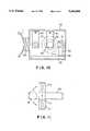
- FIG. 5A to FIG. 5Dare explanatory views of the orientation of semiconductor wafers on the intermediate transfer portion of the conveyor apparatus of the present invention.
- FIG. 6is a perspective view of a second embodiment of the conveyor apparatus of the present invention, illustrating the positional relationship between a holder arm thereof and a wafer boat.
- FIG. 7is a perspective view of essential components of the second embodiment of the conveyor apparatus of the present invention.
- FIG. 8is an explanatory view of the positional relationship between a holder arm of the conveyor apparatus and a wafer boat.
- FIG. 9is a perspective view of a third embodiment of the conveyor apparatus of the present invention.
- FIG. 10is a plan view of the third embodiment shown in FIG. 9.
- FIG. 11is a plan view of essential components of a fourth embodiment of the conveyor apparatus of the present invention.
- FIG. 1A plan view of a first embodiment of the conveyor apparatus of the present invention, applied to a thermal processing station for semiconductor wafers, is shown in FIG. 1 and a perspective view thereof is shown in FIG. 2.
- a first conveyor means 11 that conveys a semiconductor waferis provided in a first mounting chamber 1, and the first mounting chamber 1 is connected to two cassette chambers 2A and 2B that form a first conveyor access portion 20, via gate valves G1 and G2, respectively.
- the first mounting chamber 1is also connected to thermal processing portions 3A and 3B via gate valves G3 and G4, respectively, and to an intermediate transfer chamber 50 via a gate valve G5.
- the intermediate transfer chamber 50is connected via a gate valve G6 to a second mounting chamber 6 that is provided with a second conveyor means 61.
- the second mounting chamber 6is connected to two cassette chambers 7A and 7B that form a second conveyor access portion 70, via gate valves G7 and G8 respectively, and it is also connected via a gate valve G9 to a washing portion 72 for washing off and removing natural oxide layers on the surfaces of wafers W by a substance such as hydrofluoric acid.
- the first conveyor means 11 provided in the first mounting chamber 1comprises a conveyor arm 11B that is free to advance and retreat along a conveyor base 11A, and a rotational base 11C that rotates the conveyor base 11A about the center of the first mounting chamber 1.
- Five conveyor arms 11Bcould be provided stacked one above the other with spaces therebetween, as will be described below (see FIG. 3).
- the cassette chambers 2A and 2Bare provided with openable gate valves G10 and G11 that enable isolation from the outside (the atmosphere), and freely movable and rotatable turntables 21A and 21B that each support a number of wafer cassettes 21, such as five wafer cassettes, evenly spaced about the peripheries thereof.
- the cassette chamber 2Ais connected to an exhaust pipeline 23 with a vacuum pump 22 therein, a gas supply pipeline 24 of which one end is connected to a nitrogen (N 2 ) supply source, and an air pipeline 25 of which one end is connected to a factory exhaust pipeline.
- the interior of the cassette chamber 2Ais first evacuated to a prescribed degree of vacuum by the vacuum pump 22, then a continuous fresh supply of N 2 gas is passed by supplying N 2 from the gas supply pipeline 24 while exhausting it through the air pipeline 25, thus ensuring that the concentration of N 2 gas in the cassette chamber 2A is maintained constant and also that any particles generated in the cassette chamber 2A are exhausted from the cassette chamber 2A to prevent these particles from attaching to the wafers.
- the cassette chamber 2Aforms a loadlock chamber.
- the other cassette chamber 2B, the mounting chambers 1 and 6, the cassette chambers 7A and 7B, and the thermal processing portions 3A and 3Bare connected to an exhaust pipeline 23, a gas supply pipeline 24, and an air pipeline 25, in the same way as the cassette chamber 2A, to form a loadlock chamber maintained continuously in an N 2 atmosphere.
- these loadlock chambersdo not deform under reduced pressures, they are made of stainless steel plate of a thickness of, for example, 15 to 20 mm.
- the thermal processing portions 3A and 3Bare provided with process tubes 32A and 32B surrounded by heaters 31A and 31B, and wafer boats 33A and 33B which each support a large number of wafers stacked vertically and which is moved upward and downward by an elevator base between the interior of the corresponding process tube 32 and a mounting chamber at the lower side thereof.
- the intermediate transfer portion 5comprises a casing body formed of a front surface and a back surface that are open to define a first transfer opening 51A and a second transfer opening 51B, and a plurality of holder portions 51C are formed of protrusions along the two side surfaces of the casing body, for loading and holding a plurality of wafers horizontally, as shown in FIG. 3.
- a rotational mechanism 52is provided at the lower side of the intermediate transfer portion 5.
- the rotational mechanism 52has a drive portion 52A comprising a motor M1 or the like, and a turntable 52B which is rotated about a vertical axis thereof by the drive portion 52A and which has the intermediate transfer portion 5 fixed to the upper surface thereof.
- the drive portion 52Ais connected to a control portion 10.
- This control portion 10controls the drive portion 52A in accordance with the conveyor route of wafers W.
- controlis such that the wafers W are rotated through 180° after they are loaded into the intermediate transfer portion 5, in other words, the positions of the first transfer opening 51A and the second transfer opening 51B are switched. If the wafers W pass twice through the intermediate transfer portion 5, the function of the control portion 10 is to control the intermediate transfer portion 5 so that it is not rotated and the wafers W remain in the same orientation.
- the mode of control provided by the control portion 10could be set by a man-machine interface such as through a keyboard to suit different routes along which the wafers W are introduced into the thermal processing portion 3A or 3B.
- controlcould be enabled by automatically selecting either a control program under which the drive portion 52A is not rotated or one in which it is rotated, in accordance with preset modes.
- the conveyor routeis determined depending on whether wafers are introduced from the first conveyor access portion 20 or the second conveyor access portion 70, as will be described below, only two modes need be provided.
- the rotational mechanism 52is combined with an elevator mechanism 53.
- the elevator mechanism 53is configured of, for example, a planar base 53A fixed to the lower surface of the intermediate transfer portion 5, a guide portion 53C of H-shaped cross-section which extends vertically from the base 53A and which is also provided with a vertically arranged ball screw 53B driven by a motor M2, and an elevator base 53D which engages with the guide portion 53C and also is raised and lowered by the rotation of the ball screw 53B.
- the drive portion 52Ais fixed to the upper surface of the elevator base 53D.
- the second conveyor means 61 provided in the second mounting chamber 6is configured in virtually the same manner as the first conveyor means 11 described above. It differs from the first conveyor means 11, however, in that a conveyor base 61A thereof, on which a conveyor arm 61B is mounted, is configured so as to be free to move in an X direction (to left and right in FIG. 1).
- the cassette chambers 7A and 7Bare provided with gate valves G12 and G13, respectively, that open and shut off the cassette chambers from the outside, in the same manner as the cassette chambers 2A and 2B described above, and each has mounted thereon a wafer cassette 71.
- a number of wafers Wsuch as 25, which are the objects to be processed, are loaded into each of the cassettes 21 and 71 with orientation flats F thereof facing the back surface .of the cassettes, and these cassettes are set within the corresponding cassette chambers 2A, 2B, 7A, and 7B.
- N 2 gasis introduced into these chambers to provide an inert gas atmosphere therein.
- the contents of the first conveyor access portion 20are conveyed along a route (a first mode) consisting of the first mounting chamber 1 (the first conveyor means 11), the intermediate transfer portion 5, the second mounting chamber 6 (the second conveyor means 61), the washing portion 72, the second conveyor means 61, the intermediate transfer portion 5, the first conveyor means 11, and the thermal processing portion 3A (or 3B), as shown by the solid lines in FIG. 4.
- a routeconsisting of the first mounting chamber 1 (the first conveyor means 11), the intermediate transfer portion 5, the second mounting chamber 6 (the second conveyor means 61), the washing portion 72, the second conveyor means 61, the intermediate transfer portion 5, the first conveyor means 11, and the thermal processing portion 3A (or 3B), as shown by the solid lines in FIG. 4.
- the contents of the second conveyor access portion 70(in other words, the wafers W in the cassette chamber 7A or 7B), are conveyed along a route (a second mode) consisting of the second conveyor means 61, the washing portion 72, the second conveyor means 61, the intermediate transfer portion 5, the first conveyor means 11, and the thermal processing portion 3A (or 3B), as shown by the broken lines in FIG. 4.
- the transfer of wafers to and from the two conveyor means 11 and 61, the intermediate transfer portion 5, and the thermal processing portions 3A and 3Bcan be done five wafers at a time.
- the waferspass twice over the intermediate transfer portion 5. If this first mode is set in the control portion 10, the wafers W are transferred in accordance with a program under which the intermediate transfer portion 5 is not rotated when the wafers W pass over it.
- the conveyor arms 61B of the second conveyor means 61are then inserted into the intermediate transfer portion 5 through the second transfer opening 51B, the intermediate transfer portion 5 is lowered slightly so that each of the five wafers W is supported by the corresponding conveyor arm 61B, and then the conveyor arms 61B are moved backward to complete the transfer of the wafers W. After the wafers W supported on the conveyor arms 61B have been washed in the washing portion 72, the operation described above of transferring them in the first conveyor means 11 is reversed.
- FIG. 5AThe orientation of the wafers W when they are transferred from the first conveyor means 11 to the second conveyor means 61 in the first mode is shown in FIG. 5A, and their orientation when they are transferred in the opposite direction is shown in FIG. 5B.
- FIG. 5BAs is clear from these diagrams, from the point of view of each of the first conveyor means 11 and the second conveyor means 61, the orientation of the wafers W (in other words the direction in which their orientation flats F is facing) when the wafers W are transferred from the first conveyor means 11 to the second conveyor means 61 is rotated through 180°.
- the wafers Wpass once over the intermediate transfer portion 5.
- this second modeis set in the control portion 10
- the wafers Ware transferred in accordance with a program under which the intermediate transfer portion 5 is rotated through 180° when the wafers W pass over it.
- the first transfer opening 51A and the second transfer opening 51Bare switched over.
- the intermediate transfer portion 5is rotated through 180° by the drive portion 52A, and then the wafers W are transferred to the first conveyor means 11, as shown in FIG. 5C and FIG. 5D.
- the direction of the orientation flats F after the second conveyor means 61 has transferred the wafers W to the intermediate transfer portion 5would be rotated through 180°.
- the intermediate transfer portion 5rotates through 180°, and thus the wafers W are introduced into the thermal processing portion 3A (or 3B) in the orientation in which they were fetched from the cassette 71 by the second conveyor means 61.
- the wafer boat 33Ais loaded into the process tube 32A and a thermal processing such as CVD is performed on the wafers W. After undergoing the thermal processing, the wafers W that were introduced from the first conveyor access portion 20 are returned to their original cassette 21 by the first conveyor means 11, and those that were introduced from the second conveyor access portion 70 are returned to their original cassette 71 along the route of the first conveyor means 11, the intermediate transfer portion 5, and the second conveyor means 61.
- a thermal processingsuch as CVD is performed on the wafers W.
- the intermediate transfer portion 5is rotated through 180°, except that, if it is rotated, the wafers W are returned to the cassette 71 in their original orientation, so they are in the same orientation as the wafers returned to the first conveyor access portion 20 and this could be advantageous during subsequent management of the carriers.
- the orientation in which the wafers W end up in the thermal processing portion 3A (or 3B)is the same, regardless of whether the wafers W are introduced into the thermal processing portion 3A (or 3B) from the first conveyor access portion 20 or the second conveyor access portion 70. Therefore there is no need for the operator to always be conscious of the orientation of the wafers in the carriers depending on the conveyor route, and there is no need for him to set the orientation accordingly.
- the intermediate transfer portion 5has a configuration such that it can hold a plurality of wafers W, not only can a plurality of wafers be simultaneously transferred as a batch between the conveyor means 11 and 61, but also more efficient conveying can be enabled because it can also act as a sort of buffer portion to absorb any discrepancy in the timing of either of the conveyor means 11 and 61. Moreover, since the intermediate transfer portion 5 can be freely raised and lowered, there is no need to change the level of the height of the conveyor means 11 and 61, and thus the conveyor access openings for the wafers between the loadlock chambers can be made smaller and therefore the gate valves can also be made smaller.
- the intermediate transfer portion 5is not limited to a structure that can hold a plurality of wafers W; for example, a plurality of pins can be provided erected on the upper surface of the turntable 52B, and a single wafer W can be mounted on those pins.
- the intermediate transfer portion 5 in the conveyor apparatus in accordance with the present inventionis not limited to being able to move up and down; for example, the first conveyor means 11 and the second conveyor means 61 could be raised and lowered relative to the intermediate transfer portion 5 instead.
- the present inventioncan be applied to an apparatus in which the object to be processed is conveyed into the processing portion from a common conveyor opening through the first conveyor means or the second conveyor means.
- the present inventionis not limited to the conveying of wafers into a thermal processing station; it can also be applied to a processing station wherein ion implantation or ashing is performed. Similarly it can be applied to an apparatus that conveys objects in the atmosphere, or to an apparatus that conveys any object to be processed (or conveyed), not just a wafer, such as a glass substrate.
- the orientation of an object to be processedcan be controlled by the intermediate transfer portion to face in a prescribed direction to suit the conveyor route of the object to be processed, the orientation of the object to be processed at the conveyor access portion can be kept constant regardless of the conveyor route, thus facilitating management of the object to be processed.
- each of the thermal processing portions 3A and 3Bis provided with a wafer boat 80 which is moved upward and downward by an elevator base 81 between the interior of the corresponding process tube 32 (see FIG. 1) and a mounting chamber at the lower side thereof.
- This wafer boat 80has a configuration such that it can hold a large number of wafers W by supporting them vertically in grooves formed in a number (such as four) of pillars 82 to 85 thereof.
- the conveyor means 11comprises, as shown in FIG. 7, a support portion 11D that is arranged so as to be free to move along the longitudinal direction of a conveyor base 11A; five conveyor support members such as tongue-shaped conveyor arms 11B each with a base end side thereof mounted on the support portion 11D and together holding five wafers in a vertical stack so as to convey them in a batch; a movement mechanism 11E made up of components such as a ball screw 11F engaged with the lower surface of the conveyor base 11A and a guide portion 11H which is provided on the lower surface of the conveyor base 11A and which is guided by a mounting frame 11G of the ball screw 11F in such a manner as to move the conveyor base 11A in small increments in a direction across the direction of movement of the support portion 11D, such as perpendicular thereto; and a rotational base 11C which is fixed to the mounting frame 11G and which is rotated about a vertical axis by a motor M3.
- This configurationenables the conveyor arms 11B to both move forward and backward along the
- each turntable 21A and 21B of the cassette chambers 2A and 2Bare set to be equal, and that the distances from that center of rotation to each wafer boat 80 in the region on the lower side of the mounting chamber process tubes 32 of the thermal processing portions 3A and 3B are also set to be equal.
- the conveyor arms 11Bare moved forward and inserted into the wafer boat 80 between the pillars 82 to 85 thereof, the wafer boat 80 is raised slightly by the elevator base 81, and the wafers W mate with the grooves in the pillars 82 to 85 in such a manner that five wafers W are transferred simultaneously.
- the conveyor arms 11Bare then moved backward and return to fetch the next group of wafers W from within the cassette chamber 2A. In this manner, a prescribed number of unprocessed wafers are loaded into the wafer boat 80.
- the gate valve G3is closed, the wafer boat 80 is raised to load it into the process tube 32, and the prescribed thermal processing, such as CVD, is performed on the wafers W. Subsequently, the wafer boat 80 is lowered to unload it from the process tube 32, and, by an operation the reverse of that described above, the processed wafers W are fetched out of the wafer boat 80 by the conveyor arms 11B and are returned to their original cassette 21 in the cassette chamber 2A. In this case, depending on the mode, various different routes could be utilized.
- the processed wafers Wcould be introduced into the other thermal processing portion 3B and subjected to a different thermal processing, or wafers W fetched from the cassette chamber 2A on one side could be transferred to the cassette chamber 2B on the other side after they have been processed.
- the conveyor base 11A of the conveyor means 11is rotated together with the rotational base 11C in such a manner that the axial line (k) of the conveyor base 11A (the axial line of the conveyor arms 11B ends up perpendicular to the line (m) joining the pillars 82 and 85. If the ball screw 11F is also driven, the conveyor base 11A can be moved sideways until the axial line (k) is positioned passing through the center of the opening in the wafer boat 80.
- the conveyor arms 11BAfter the conveyor arms 11B have been positioned in this manner, the wafers W inserted into the wafer boat 80 are transferred. If the opening of the wafer boat 80 is accurately aligned with respect to the center of rotation (a), as it is designed to be, the conveyor arms 11B are moved forward for a setting at a reference position (shown by the solid lines in FIG. 8).
- the conveyor arms 11Balways pass through the center of the opening on the wafer boat 80, so that the clearance between the pillars 82 and 83 on the left and the pillars 84 and 85 on the right is balanced, and thus the wafers W can be accurately conveyed, in other words, fetched and transferred.
- This contrivanceneed not be limited to a wafer boat 80; the same effect can be obtained when the conveyor arms 11B are conveying wafers W between the cassette in the cassette chamber 2A or 2B and the intermediate transfer portion 5 within the intermediate transfer chamber 50.
- the configurationcould be such that the conveyor base 11A is fixed onto the rotational base 11C of the conveyor means 11, and the rotational base 11C is moved sideways.
- the conveyor arms 11B combined with the elevator mechanismneed not be raised and lowered, and the number of conveyor arms 11B need not be limited to five, for example there could be just one conveyor arm 11B.
- the thermal processing portions 3A and 3Bcould also be configured as shown in FIG. 9 and FIG. 10.
- another embodiment of the present invention shown in FIG. 9 and FIG. 10is provided with a separate elevator base 87 that is integral with a reciprocating elevator base 81 that reciprocates at a position on the side of the mounting chamber 1 closer than the center of the process tube 32 when the wafers W are exchanged.
- the wafer boat 80 that forms the portion holding the objects to be processedreciprocates between the two elevator bases 81 and 87 of a thus-configured reciprocating mechanism 90.
- the reciprocating mechanism 90has a support arm 91 that mates with the lower surface of a flange portion 86 into which a cylindrical component at the lower end of the wafer boat 80 is inserted, an elevator mechanism 92 that raises and lowers the support arm 91, and a horizontal drive mechanism 93 that moves the elevator mechanism 92 in a horizontal direction (the direction of the arrows).
- the wafer boat 80 unloaded from the process tube 32is removed from the elevator base 81 by the reciprocating mechanism 90 and moved toward the elevator base 87, and the wafers W in the wafer boat 80 are fetched by the conveyor means 11 and also unprocessed wafers W are transferred into the wafer boat 80. Subsequently, the wafer boat 80 is moved back to the elevator base 81 by the reciprocating mechanism 90 and is loaded into the process tube 32.
- the stroke of the conveyor arms 11B of the conveyor means 11is determined by the position of the process tube 32.
- the wafer boat 80is moved in a reciprocal fashion as described above, the wafer boat 80 can be placed extremely close to the conveyor means 11, and thus the stroke of the conveyor arms 11B can be made shorter. Therefore, not only the conveyor means 11 but also the mounting chamber 1 can be made smaller, which has the advantage of strengthening the mounting chamber 1 in its role as a loadlock chamber and also the amount by which the stroke is shortened has the effect of reducing the effect on the conveying of wafers W, caused by design errors in components such as the rotational mechanism of the conveyor means 11.
- the wafers Wcan be transferred by using the reciprocating mechanism 90 to move the conveyor means 11 while it is supporting the wafer boat 80.
- This apparatus that reciprocatescan also be applied to a lateral type of thermal processing portion, and a conveyor means can be used that does not have a movement mechanism that moves laterally, as in the previous embodiments.
- the conveyor means 11can use different types of conveyor arm 11B to support the wafers to be conveyed.
- a tip portion 11J of each conveyor arm 11Bcould be configured so as to be free to rotate and also have wafer support portions 11K and 11L formed in two end portions thereof, so that the tip portion 11J can be rotated to bring either of the wafer support portions 11K and 11L into use as required.
Landscapes
- Engineering & Computer Science (AREA)
- Physics & Mathematics (AREA)
- Condensed Matter Physics & Semiconductors (AREA)
- General Physics & Mathematics (AREA)
- Manufacturing & Machinery (AREA)
- Computer Hardware Design (AREA)
- Microelectronics & Electronic Packaging (AREA)
- Power Engineering (AREA)
- Container, Conveyance, Adherence, Positioning, Of Wafer (AREA)
Abstract
Description
Claims (13)
Applications Claiming Priority (4)
| Application Number | Priority Date | Filing Date | Title |
|---|---|---|---|
| JP4-152808 | 1992-05-20 | ||
| JP15280892AJPH05319513A (en) | 1992-05-20 | 1992-05-20 | Transport device |
| JP4-154337 | 1992-05-21 | ||
| JP15433792AJP3380570B2 (en) | 1992-05-21 | 1992-05-21 | Transfer device |
Publications (1)
| Publication Number | Publication Date |
|---|---|
| US5404894Atrue US5404894A (en) | 1995-04-11 |
Family
ID=26481619
Family Applications (1)
| Application Number | Title | Priority Date | Filing Date |
|---|---|---|---|
| US08/062,611Expired - Fee RelatedUS5404894A (en) | 1992-05-20 | 1993-05-18 | Conveyor apparatus |
Country Status (1)
| Country | Link |
|---|---|
| US (1) | US5404894A (en) |
Cited By (133)
| Publication number | Priority date | Publication date | Assignee | Title |
|---|---|---|---|---|
| US5486080A (en)* | 1994-06-30 | 1996-01-23 | Diamond Semiconductor Group, Inc. | High speed movement of workpieces in vacuum processing |
| US5565034A (en)* | 1993-10-29 | 1996-10-15 | Tokyo Electron Limited | Apparatus for processing substrates having a film formed on a surface of the substrate |
| US5570987A (en)* | 1993-12-14 | 1996-11-05 | W. L. Gore & Associates, Inc. | Semiconductor wafer transport container |
| US5575611A (en)* | 1994-10-13 | 1996-11-19 | Semitool, Inc. | Wafer transfer apparatus |
| US5603777A (en)* | 1994-06-27 | 1997-02-18 | Dainippon Screen Mfg. Co., Ltd. | Substrate surface treating apparatus and substrate surface treating method |
| US5609459A (en)* | 1995-07-06 | 1997-03-11 | Brooks Automation, Inc. | Door drive mechanisms for substrate carrier and load lock |
| US5695564A (en)* | 1994-08-19 | 1997-12-09 | Tokyo Electron Limited | Semiconductor processing system |
| US5730574A (en)* | 1995-10-09 | 1998-03-24 | Dainippon Screen Mfg. Co., Ltd. | Transfer apparatus for and method of transferring substrate |
| US5751003A (en)* | 1996-02-16 | 1998-05-12 | Eaton Corporation | Loadlock assembly for an ion implantation system |
| US5760405A (en)* | 1996-02-16 | 1998-06-02 | Eaton Corporation | Plasma chamber for controlling ion dosage in ion implantation |
| US5788447A (en)* | 1995-08-05 | 1998-08-04 | Kokusai Electric Co., Ltd. | Substrate processing apparatus |
| US5793050A (en)* | 1996-02-16 | 1998-08-11 | Eaton Corporation | Ion implantation system for implanting workpieces |
| US5807062A (en)* | 1995-12-28 | 1998-09-15 | Jenoptik Aktiengesellschaft | Arrangement for handling wafer-shaped objects |
| US5811823A (en)* | 1996-02-16 | 1998-09-22 | Eaton Corporation | Control mechanisms for dosimetry control in ion implantation systems |
| US5810028A (en)* | 1996-06-25 | 1998-09-22 | Speedfam Co., Ltd. | Washing apparatus for disc-like workpieces |
| US5820679A (en)* | 1993-07-15 | 1998-10-13 | Hitachi, Ltd. | Fabrication system and method having inter-apparatus transporter |
| US5825470A (en)* | 1995-03-14 | 1998-10-20 | Nikon Corporation | Exposure apparatus |
| US5825038A (en)* | 1996-11-26 | 1998-10-20 | Eaton Corporation | Large area uniform ion beam formation |
| US5828070A (en)* | 1996-02-16 | 1998-10-27 | Eaton Corporation | System and method for cooling workpieces processed by an ion implantation system |
| US5830272A (en)* | 1995-11-07 | 1998-11-03 | Sputtered Films, Inc. | System for and method of providing a controlled deposition on wafers |
| US5895923A (en)* | 1996-02-16 | 1999-04-20 | Eaton Corporation | Ion beam shield for implantation systems |
| US5935330A (en)* | 1997-01-24 | 1999-08-10 | Electroplating Engineers Of Japan Ltd. | Automatic wafer plating equipment |
| US5976919A (en)* | 1994-06-10 | 1999-11-02 | Matsushita Electric Industrial Co., Ltd. | Apparatus and method of manufacturing semiconductor element |
| US5997290A (en)* | 1996-08-30 | 1999-12-07 | Hillingrathner; Franz | Revolving transfer furnace for treating workpieces |
| US6019564A (en)* | 1995-10-27 | 2000-02-01 | Advantest Corporation | Semiconductor device transporting and handling apparatus |
| US6048162A (en)* | 1997-08-28 | 2000-04-11 | Cvc Products, Inc. | Wafer handler for multi-station tool |
| US6056544A (en)* | 1998-05-02 | 2000-05-02 | Samsung Electronics Co., Ltd. | Apparatus for baking resists on semiconductor wafers |
| US6071055A (en)* | 1997-09-30 | 2000-06-06 | Applied Materials, Inc. | Front end vacuum processing environment |
| US6091498A (en)* | 1996-07-15 | 2000-07-18 | Semitool, Inc. | Semiconductor processing apparatus having lift and tilt mechanism |
| US6120229A (en)* | 1999-02-01 | 2000-09-19 | Brooks Automation Inc. | Substrate carrier as batchloader |
| US6125862A (en)* | 1996-10-02 | 2000-10-03 | Sankyo Seiki Mfg. Co., Ltd. | Cleaning apparatus |
| US6132165A (en)* | 1998-02-23 | 2000-10-17 | Applied Materials, Inc. | Single drive, dual plane robot |
| US6158941A (en)* | 1995-10-27 | 2000-12-12 | Brooks Automation, Inc. | Substrate transport apparatus with double substrate holders |
| US6193506B1 (en) | 1995-05-24 | 2001-02-27 | Brooks Automation, Inc. | Apparatus and method for batch thermal conditioning of substrates |
| US6234788B1 (en)* | 1998-11-05 | 2001-05-22 | Applied Science And Technology, Inc. | Disk furnace for thermal processing |
| WO2001049894A1 (en)* | 2000-01-03 | 2001-07-12 | Skion Corporation | Multi wafer introduction/single wafer conveyor mode processing system and method of processing wafers using the same |
| US6280134B1 (en)* | 1997-06-17 | 2001-08-28 | Applied Materials, Inc. | Apparatus and method for automated cassette handling |
| US6305895B1 (en)* | 1998-12-25 | 2001-10-23 | Tokyo Electron Limited | Transfer system for vacuum process equipment |
| US20010035346A1 (en)* | 1998-04-24 | 2001-11-01 | Keiichi Maeda | Apparatus and method for electroplating |
| US20020034886A1 (en)* | 2000-09-15 | 2002-03-21 | Applied Materials, Inc. | Double dual slot load lock for process equipment |
| US6371354B2 (en) | 1999-10-08 | 2002-04-16 | Seho Systemtechnik Gmbh | Apparatus for the temperature regulation of electronic components |
| US6450750B1 (en)* | 1997-07-28 | 2002-09-17 | Applied Materials, Inc. | Multiple loadlock system |
| US6462411B1 (en)* | 1997-12-05 | 2002-10-08 | Kokusai Electric Co., Ltd | Semiconductor wafer processing apparatus for transferring a wafer mount |
| US6464448B1 (en) | 1998-09-01 | 2002-10-15 | Brooks Automation, Inc. | Substrate transport apparatus |
| US6473157B2 (en)* | 1992-02-07 | 2002-10-29 | Nikon Corporation | Method of manufacturing exposure apparatus and method for exposing a pattern on a mask onto a substrate |
| US6481956B1 (en) | 1995-10-27 | 2002-11-19 | Brooks Automation Inc. | Method of transferring substrates with two different substrate holding end effectors |
| US20030027085A1 (en)* | 1997-05-27 | 2003-02-06 | Mullee William H. | Removal of photoresist and photoresist residue from semiconductors using supercritical carbon dioxide process |
| US6547510B1 (en) | 1998-05-04 | 2003-04-15 | Brooks Automation Inc. | Substrate transport apparatus with coaxial drive shafts and dual independent scara arms |
| US6572320B2 (en) | 1997-05-05 | 2003-06-03 | Semitool, Inc. | Robot for handling workpieces in an automated processing system |
| US20030113188A1 (en)* | 2001-12-17 | 2003-06-19 | Applied Materials, Inc. | Mechanism for providing a continuous supply of wafers and cassettes to semiconductor fabrication tool |
| US20030121535A1 (en)* | 1999-11-02 | 2003-07-03 | Biberger Maximilian Albert | Method for supercritical processing of multiple workpieces |
| US20030150559A1 (en)* | 1999-11-02 | 2003-08-14 | Biberger Maximilian Albert | Apparatus for supercritical processing of a workpiece |
| US20030155541A1 (en)* | 2002-02-15 | 2003-08-21 | Supercritical Systems, Inc. | Pressure enhanced diaphragm valve |
| US6643563B2 (en) | 2001-07-13 | 2003-11-04 | Brooks Automation, Inc. | Trajectory planning and motion control strategies for a planar three-degree-of-freedom robotic arm |
| US6645355B2 (en) | 1996-07-15 | 2003-11-11 | Semitool, Inc. | Semiconductor processing apparatus having lift and tilt mechanism |
| US20040040660A1 (en)* | 2001-10-03 | 2004-03-04 | Biberger Maximilian Albert | High pressure processing chamber for multiple semiconductor substrates |
| US6722642B1 (en) | 2002-11-06 | 2004-04-20 | Tokyo Electron Limited | High pressure compatible vacuum chuck for semiconductor wafer including lift mechanism |
| US6722834B1 (en)* | 1997-10-08 | 2004-04-20 | Applied Materials, Inc. | Robot blade with dual offset wafer supports |
| US6748293B1 (en) | 2003-03-24 | 2004-06-08 | Varian Semiconductor Equipment Associates, Inc. | Methods and apparatus for high speed object handling |
| EP0948031A3 (en)* | 1998-03-31 | 2004-06-09 | NEC Electronics Corporation | Semiconductor fabrication line with contamination preventing function |
| US20040157420A1 (en)* | 2003-02-06 | 2004-08-12 | Supercritical Systems, Inc. | Vacuum chuck utilizing sintered material and method of providing thereof |
| US20040157463A1 (en)* | 2003-02-10 | 2004-08-12 | Supercritical Systems, Inc. | High-pressure processing chamber for a semiconductor wafer |
| US20040167743A1 (en)* | 2002-12-20 | 2004-08-26 | Martin Hosek | System and method for on-the-fly eccentricity recognition |
| US6814573B2 (en)* | 2001-12-14 | 2004-11-09 | Jh Corporation | Vacuum heat-treatment apparatus |
| US20040258504A1 (en)* | 2001-08-28 | 2004-12-23 | Kazuyoshi Yasukawa | Heating and cooling system and production system including this heating and cooling system |
| US20050000651A1 (en)* | 2000-07-26 | 2005-01-06 | Biberger Maximilian A. | High pressure processing chamber for semiconductor substrate |
| US20050005850A1 (en)* | 1999-07-23 | 2005-01-13 | Semiconductor Energy Laboratory Co., Ltd. | Method of fabricating an EL display device, and apparatus for forming a thin film |
| US20050016454A1 (en)* | 1999-12-15 | 2005-01-27 | Applied Materials, Inc. | Dual substrate loadlock process equipment |
| US20050034660A1 (en)* | 2003-08-11 | 2005-02-17 | Supercritical Systems, Inc. | Alignment means for chamber closure to reduce wear on surfaces |
| US20050045214A1 (en)* | 1994-04-28 | 2005-03-03 | Semitool, Inc. | Automated semiconductor processing systems |
| US20050095088A1 (en)* | 2003-10-20 | 2005-05-05 | Applied Materials, Inc. | Load lock chamber for large area substrate processing system |
| US20050150757A1 (en)* | 1997-03-17 | 2005-07-14 | Applied Komatsu Technology, Inc. | Heated and cooled vacuum chamber shield |
| US6960057B1 (en) | 1998-09-30 | 2005-11-01 | Brooks Automation, Inc. | Substrate transport apparatus |
| US20060003592A1 (en)* | 2004-06-30 | 2006-01-05 | Tokyo Electron Limited | System and method for processing a substrate using supercritical carbon dioxide processing |
| US7001468B1 (en) | 2002-02-15 | 2006-02-21 | Tokyo Electron Limited | Pressure energized pressure vessel opening and closing device and method of providing therefor |
| US20060068583A1 (en)* | 2004-09-29 | 2006-03-30 | Tokyo Electron Limited | A method for supercritical carbon dioxide processing of fluoro-carbon films |
| US20060065288A1 (en)* | 2004-09-30 | 2006-03-30 | Darko Babic | Supercritical fluid processing system having a coating on internal members and a method of using |
| US20060073041A1 (en)* | 2004-10-05 | 2006-04-06 | Supercritical Systems Inc. | Temperature controlled high pressure pump |
| US20060102208A1 (en)* | 2004-11-12 | 2006-05-18 | Tokyo Electron Limited | System for removing a residue from a substrate using supercritical carbon dioxide processing |
| US20060102204A1 (en)* | 2004-11-12 | 2006-05-18 | Tokyo Electron Limited | Method for removing a residue from a substrate using supercritical carbon dioxide processing |
| US20060104831A1 (en)* | 2004-11-12 | 2006-05-18 | Tokyo Electron Limited | Method and system for cooling a pump |
| US20060102590A1 (en)* | 2004-11-12 | 2006-05-18 | Tokyo Electron Limited | Method for treating a substrate with a high pressure fluid using a preoxide-based process chemistry |
| US20060102591A1 (en)* | 2004-11-12 | 2006-05-18 | Tokyo Electron Limited | Method and system for treating a substrate using a supercritical fluid |
| US20060130875A1 (en)* | 2004-12-22 | 2006-06-22 | Alexei Sheydayi | Method and apparatus for clamping a substrate in a high pressure processing system |
| US20060130966A1 (en)* | 2004-12-20 | 2006-06-22 | Darko Babic | Method and system for flowing a supercritical fluid in a high pressure processing system |
| US20060130913A1 (en)* | 2004-12-22 | 2006-06-22 | Alexei Sheydayi | Non-contact shuttle valve for flow diversion in high pressure systems |
| US20060135047A1 (en)* | 2004-12-22 | 2006-06-22 | Alexei Sheydayi | Method and apparatus for clamping a substrate in a high pressure processing system |
| US20060151735A1 (en)* | 2004-06-14 | 2006-07-13 | Jae-Chull Lee | Curved slit valve door with flexible coupling |
| US20060180573A1 (en)* | 2005-02-15 | 2006-08-17 | Tokyo Electron Limited | Method and system for treating a substrate with a high pressure fluid using fluorosilicic acid |
| US20060180174A1 (en)* | 2005-02-15 | 2006-08-17 | Tokyo Electron Limited | Method and system for treating a substrate with a high pressure fluid using a peroxide-based process chemistry in conjunction with an initiator |
| US20060180572A1 (en)* | 2005-02-15 | 2006-08-17 | Tokyo Electron Limited | Removal of post etch residue for a substrate with open metal surfaces |
| US20060180175A1 (en)* | 2005-02-15 | 2006-08-17 | Parent Wayne M | Method and system for determining flow conditions in a high pressure processing system |
| US20060182615A1 (en)* | 2001-09-21 | 2006-08-17 | Shinichi Kurita | Method for transferring substrates in a load lock chamber |
| US20060255012A1 (en)* | 2005-05-10 | 2006-11-16 | Gunilla Jacobson | Removal of particles from substrate surfaces using supercritical processing |
| US20060254615A1 (en)* | 2005-05-13 | 2006-11-16 | Tokyo Electron Limited | Treatment of substrate using functionalizing agent in supercritical carbon dioxide |
| US20060263177A1 (en)* | 2003-11-10 | 2006-11-23 | Meulen Peter V D | Linear semiconductor processing facilities |
| US20060266287A1 (en)* | 2005-05-25 | 2006-11-30 | Parent Wayne M | Method and system for passivating a processing chamber |
| US20060273815A1 (en)* | 2005-06-06 | 2006-12-07 | Applied Materials, Inc. | Substrate support with integrated prober drive |
| US20070006936A1 (en)* | 2005-07-07 | 2007-01-11 | Applied Materials, Inc. | Load lock chamber with substrate temperature regulation |
| US7163380B2 (en) | 2003-07-29 | 2007-01-16 | Tokyo Electron Limited | Control of fluid flow in the processing of an object with a fluid |
| US20070012337A1 (en)* | 2005-07-15 | 2007-01-18 | Tokyo Electron Limited | In-line metrology for supercritical fluid processing |
| US20070020082A1 (en)* | 2005-07-11 | 2007-01-25 | Caveney Robert T | Unequal link SCARA arm |
| US7225820B2 (en) | 2003-02-10 | 2007-06-05 | Tokyo Electron Limited | High-pressure processing chamber for a semiconductor wafer |
| US20070166133A1 (en)* | 2006-01-13 | 2007-07-19 | Applied Materials, Inc. | Decoupled chamber body |
| US20070280816A1 (en)* | 2006-06-02 | 2007-12-06 | Shinichi Kurita | Multiple slot load lock chamber and method of operation |
| US20080087214A1 (en)* | 2006-08-04 | 2008-04-17 | Jae-Chull Lee | Load lock chamber with decoupled slit valve door seal compartment |
| US7380984B2 (en) | 2005-03-28 | 2008-06-03 | Tokyo Electron Limited | Process flow thermocouple |
| US20080138176A1 (en)* | 2006-12-12 | 2008-06-12 | Semes Co., Ltd. | Apparatus for manufacturing semiconductor device |
| US7387868B2 (en) | 2002-03-04 | 2008-06-17 | Tokyo Electron Limited | Treatment of a dielectric layer using supercritical CO2 |
| US20080168815A1 (en)* | 2004-12-23 | 2008-07-17 | Michael Jonathan Coates | Multi-Stage Process Handling Equipment |
| US20080251019A1 (en)* | 2007-04-12 | 2008-10-16 | Sriram Krishnaswami | System and method for transferring a substrate into and out of a reduced volume chamber accommodating multiple substrates |
| US20080302281A1 (en)* | 2005-11-23 | 2008-12-11 | Bernard William J | Surface Treatment of Metallic Articles in an Atmospheric Furnace |
| US7494107B2 (en) | 2005-03-30 | 2009-02-24 | Supercritical Systems, Inc. | Gate valve for plus-atmospheric pressure semiconductor process vessels |
| US20090087807A1 (en)* | 2007-10-02 | 2009-04-02 | United Microelectronics Corp. | Method of semiconductor process and semiconductor apparatus system |
| US20090170047A1 (en)* | 2008-01-01 | 2009-07-02 | Dongguan Anwell Digital Machinery Ltd. | Method and system for thermal processing of objects in chambers |
| US7767145B2 (en) | 2005-03-28 | 2010-08-03 | Toyko Electron Limited | High pressure fourier transform infrared cell |
| US7845618B2 (en) | 2006-06-28 | 2010-12-07 | Applied Materials, Inc. | Valve door with ball coupling |
| US20120107082A1 (en)* | 2010-05-07 | 2012-05-03 | Thermo Electron Led Gmbh | Climate Cabinet Having Multiple Intake and Output Stations |
| US20120152168A1 (en)* | 2005-01-21 | 2012-06-21 | Kabushiki Kaisha Toshiba | Semiconductor device having oxidized metal film and manufacture method of the same |
| US20120213613A1 (en)* | 2011-02-18 | 2012-08-23 | De Ridder Chris G M | Wafer boat assembly, loading apparatus comprising such a wafer boat assembly and method for loading a vertical furnace |
| US20140064886A1 (en)* | 2012-08-30 | 2014-03-06 | Orbotech LT Solar, LLC. | System, architecture and method for simultaneous transfer and process of substrates |
| EP2481530A3 (en)* | 2010-09-16 | 2014-11-26 | Tokyo Electron Limited | Transfer device, processing system, control method of transfer device, and computer-readable storage medium |
| US9177844B2 (en) | 2012-11-27 | 2015-11-03 | Denso Corporation | Transport system |
| US9202733B2 (en) | 2011-11-07 | 2015-12-01 | Persimmon Technologies Corporation | Robot system with independent arms |
| US9287152B2 (en) | 2009-12-10 | 2016-03-15 | Orbotech LT Solar, LLC. | Auto-sequencing multi-directional inline processing method |
| US9401296B2 (en) | 2011-11-29 | 2016-07-26 | Persimmon Technologies Corporation | Vacuum robot adapted to grip and transport a substrate and method thereof with passive bias |
| US9462921B2 (en) | 2011-05-24 | 2016-10-11 | Orbotech LT Solar, LLC. | Broken wafer recovery system |
| US10014199B2 (en)* | 2015-11-18 | 2018-07-03 | Tokyo Electron Limited | Wafer boat support table and heat treatment apparatus using the same |
| WO2018219424A1 (en)* | 2017-05-29 | 2018-12-06 | Applied Materials Italia S.R.L. | Method and apparatus for use in substrate processing |
| US10811294B2 (en)* | 2016-09-20 | 2020-10-20 | Wonik Ips Co., Ltd. | Substrate transfer apparatus and control method thereof |
| US10998209B2 (en)* | 2019-05-31 | 2021-05-04 | Applied Materials, Inc. | Substrate processing platforms including multiple processing chambers |
| US11226368B2 (en)* | 2019-08-26 | 2022-01-18 | Tokyo Electron Limited | Placement apparatus control method, placement apparatus, and inspection apparatus |
| US20220044968A1 (en)* | 2020-08-10 | 2022-02-10 | Applied Materials, Inc. | Mainframe-less wafer transfer platform for wafer processing modules |
Citations (22)
| Publication number | Priority date | Publication date | Assignee | Title |
|---|---|---|---|---|
| US4550242A (en)* | 1981-10-05 | 1985-10-29 | Tokyo Denshi Kagaku Kabushiki Kaisha | Automatic plasma processing device and heat treatment device for batch treatment of workpieces |
| US4715921A (en)* | 1986-10-24 | 1987-12-29 | General Signal Corporation | Quad processor |
| US4715764A (en)* | 1986-04-28 | 1987-12-29 | Varian Associates, Inc. | Gate valve for wafer processing system |
| US4770590A (en)* | 1986-05-16 | 1988-09-13 | Silicon Valley Group, Inc. | Method and apparatus for transferring wafers between cassettes and a boat |
| US4781511A (en)* | 1986-03-25 | 1988-11-01 | Shimizu Construction Co., Ltd. | Semiconductor processing system |
| US4785962A (en)* | 1987-04-20 | 1988-11-22 | Applied Materials, Inc. | Vacuum chamber slit valve |
| US4825808A (en)* | 1986-12-19 | 1989-05-02 | Anelva Corporation | Substrate processing apparatus |
| JPH0276261A (en)* | 1988-09-12 | 1990-03-15 | Fuji Xerox Co Ltd | Manufacture of image sensor |
| US4923054A (en)* | 1987-11-27 | 1990-05-08 | Dainippon Screen Mfg. Co., Ltd. | Wafer transfer apparatus having an improved wafer transfer portion |
| JPH02122541A (en)* | 1988-10-31 | 1990-05-10 | Toshiba Ceramics Co Ltd | Transfer device for semiconductor wafer |
| WO1990010949A1 (en)* | 1989-03-06 | 1990-09-20 | Asm International N.V. | Method for depositing a layer on a substrate and also a processing system for that purpose |
| US4962726A (en)* | 1987-11-10 | 1990-10-16 | Matsushita Electric Industrial Co., Ltd. | Chemical vapor deposition reaction apparatus having isolated reaction and buffer chambers |
| US4990047A (en)* | 1988-05-24 | 1991-02-05 | Balzers Aktiengesellschaft | Vacuum apparatus |
| WO1991004213A1 (en)* | 1989-09-12 | 1991-04-04 | Rapro Technology, Inc. | Automated wafer transport system |
| US5026239A (en)* | 1988-09-06 | 1991-06-25 | Canon Kabushiki Kaisha | Mask cassette and mask cassette loading device |
| JPH0426138A (en)* | 1990-05-21 | 1992-01-29 | Tokyo Electron Sagami Ltd | Conveyor for platelike element |
| US5096364A (en)* | 1986-04-28 | 1992-03-17 | Varian Associates, Inc. | Wafer arm handler mechanism |
| JPH04106952A (en)* | 1990-08-27 | 1992-04-08 | Kokusai Electric Co Ltd | semiconductor manufacturing equipment |
| US5110248A (en)* | 1989-07-17 | 1992-05-05 | Tokyo Electron Sagami Limited | Vertical heat-treatment apparatus having a wafer transfer mechanism |
| US5174067A (en)* | 1990-10-19 | 1992-12-29 | Shin-Etsu Handotai Co., Ltd. | Automatic wafer lapping apparatus |
| US5217340A (en)* | 1989-01-28 | 1993-06-08 | Kokusai Electric Co., Ltd. | Wafer transfer mechanism in vertical CVD diffusion apparatus |
| US5234303A (en)* | 1990-05-15 | 1993-08-10 | Seiko Instruments Inc. | In-vacuum conveyance robot |
- 1993
- 1993-05-18USUS08/062,611patent/US5404894A/ennot_activeExpired - Fee Related
Patent Citations (22)
| Publication number | Priority date | Publication date | Assignee | Title |
|---|---|---|---|---|
| US4550242A (en)* | 1981-10-05 | 1985-10-29 | Tokyo Denshi Kagaku Kabushiki Kaisha | Automatic plasma processing device and heat treatment device for batch treatment of workpieces |
| US4781511A (en)* | 1986-03-25 | 1988-11-01 | Shimizu Construction Co., Ltd. | Semiconductor processing system |
| US5096364A (en)* | 1986-04-28 | 1992-03-17 | Varian Associates, Inc. | Wafer arm handler mechanism |
| US4715764A (en)* | 1986-04-28 | 1987-12-29 | Varian Associates, Inc. | Gate valve for wafer processing system |
| US4770590A (en)* | 1986-05-16 | 1988-09-13 | Silicon Valley Group, Inc. | Method and apparatus for transferring wafers between cassettes and a boat |
| US4715921A (en)* | 1986-10-24 | 1987-12-29 | General Signal Corporation | Quad processor |
| US4825808A (en)* | 1986-12-19 | 1989-05-02 | Anelva Corporation | Substrate processing apparatus |
| US4785962A (en)* | 1987-04-20 | 1988-11-22 | Applied Materials, Inc. | Vacuum chamber slit valve |
| US4962726A (en)* | 1987-11-10 | 1990-10-16 | Matsushita Electric Industrial Co., Ltd. | Chemical vapor deposition reaction apparatus having isolated reaction and buffer chambers |
| US4923054A (en)* | 1987-11-27 | 1990-05-08 | Dainippon Screen Mfg. Co., Ltd. | Wafer transfer apparatus having an improved wafer transfer portion |
| US4990047A (en)* | 1988-05-24 | 1991-02-05 | Balzers Aktiengesellschaft | Vacuum apparatus |
| US5026239A (en)* | 1988-09-06 | 1991-06-25 | Canon Kabushiki Kaisha | Mask cassette and mask cassette loading device |
| JPH0276261A (en)* | 1988-09-12 | 1990-03-15 | Fuji Xerox Co Ltd | Manufacture of image sensor |
| JPH02122541A (en)* | 1988-10-31 | 1990-05-10 | Toshiba Ceramics Co Ltd | Transfer device for semiconductor wafer |
| US5217340A (en)* | 1989-01-28 | 1993-06-08 | Kokusai Electric Co., Ltd. | Wafer transfer mechanism in vertical CVD diffusion apparatus |
| WO1990010949A1 (en)* | 1989-03-06 | 1990-09-20 | Asm International N.V. | Method for depositing a layer on a substrate and also a processing system for that purpose |
| US5110248A (en)* | 1989-07-17 | 1992-05-05 | Tokyo Electron Sagami Limited | Vertical heat-treatment apparatus having a wafer transfer mechanism |
| WO1991004213A1 (en)* | 1989-09-12 | 1991-04-04 | Rapro Technology, Inc. | Automated wafer transport system |
| US5234303A (en)* | 1990-05-15 | 1993-08-10 | Seiko Instruments Inc. | In-vacuum conveyance robot |
| JPH0426138A (en)* | 1990-05-21 | 1992-01-29 | Tokyo Electron Sagami Ltd | Conveyor for platelike element |
| JPH04106952A (en)* | 1990-08-27 | 1992-04-08 | Kokusai Electric Co Ltd | semiconductor manufacturing equipment |
| US5174067A (en)* | 1990-10-19 | 1992-12-29 | Shin-Etsu Handotai Co., Ltd. | Automatic wafer lapping apparatus |
Cited By (198)
| Publication number | Priority date | Publication date | Assignee | Title |
|---|---|---|---|---|
| US6473157B2 (en)* | 1992-02-07 | 2002-10-29 | Nikon Corporation | Method of manufacturing exposure apparatus and method for exposing a pattern on a mask onto a substrate |
| US20060111802A1 (en)* | 1993-07-15 | 2006-05-25 | Renesas Technology Corp. | Fabrication system and fabrication method |
| US5858863A (en)* | 1993-07-15 | 1999-01-12 | Hitachi, Ltd. | Fabrication system and method having inter-apparatus transporter |
| US20040107020A1 (en)* | 1993-07-15 | 2004-06-03 | Hitachi, Ltd. | Fabrication system and fabrication method |
| US5820679A (en)* | 1993-07-15 | 1998-10-13 | Hitachi, Ltd. | Fabrication system and method having inter-apparatus transporter |
| US6099598A (en)* | 1993-07-15 | 2000-08-08 | Hitachi, Ltd. | Fabrication system and fabrication method |
| US7310563B2 (en) | 1993-07-15 | 2007-12-18 | Renesas Technology Corp. | Fabrication system and fabrication method |
| US7392106B2 (en) | 1993-07-15 | 2008-06-24 | Renesas Technology Corp. | Fabrication system and fabrication method |
| US7062344B2 (en) | 1993-07-15 | 2006-06-13 | Renesas Technology Corp. | Fabrication system and fabrication method |
| US20100131093A1 (en)* | 1993-07-15 | 2010-05-27 | Renesas Technology Corp. | Fabrication system and fabrication method |
| US7603194B2 (en) | 1993-07-15 | 2009-10-13 | Renesas Technology Corp. | Fabrication system and fabrication method |
| US5565034A (en)* | 1993-10-29 | 1996-10-15 | Tokyo Electron Limited | Apparatus for processing substrates having a film formed on a surface of the substrate |
| US5570987A (en)* | 1993-12-14 | 1996-11-05 | W. L. Gore & Associates, Inc. | Semiconductor wafer transport container |
| US7080652B2 (en)* | 1994-04-28 | 2006-07-25 | Semitool, Inc. | Automated semiconductor processing systems |
| US20050045214A1 (en)* | 1994-04-28 | 2005-03-03 | Semitool, Inc. | Automated semiconductor processing systems |
| US5976919A (en)* | 1994-06-10 | 1999-11-02 | Matsushita Electric Industrial Co., Ltd. | Apparatus and method of manufacturing semiconductor element |
| US5603777A (en)* | 1994-06-27 | 1997-02-18 | Dainippon Screen Mfg. Co., Ltd. | Substrate surface treating apparatus and substrate surface treating method |
| US5486080A (en)* | 1994-06-30 | 1996-01-23 | Diamond Semiconductor Group, Inc. | High speed movement of workpieces in vacuum processing |
| US5695564A (en)* | 1994-08-19 | 1997-12-09 | Tokyo Electron Limited | Semiconductor processing system |
| US5590996A (en)* | 1994-10-13 | 1997-01-07 | Semitherm | Wafer transfer apparatus |
| US5575611A (en)* | 1994-10-13 | 1996-11-19 | Semitool, Inc. | Wafer transfer apparatus |
| US5825470A (en)* | 1995-03-14 | 1998-10-20 | Nikon Corporation | Exposure apparatus |
| US6193506B1 (en) | 1995-05-24 | 2001-02-27 | Brooks Automation, Inc. | Apparatus and method for batch thermal conditioning of substrates |
| US5609459A (en)* | 1995-07-06 | 1997-03-11 | Brooks Automation, Inc. | Door drive mechanisms for substrate carrier and load lock |
| US5788447A (en)* | 1995-08-05 | 1998-08-04 | Kokusai Electric Co., Ltd. | Substrate processing apparatus |
| US6143083A (en)* | 1995-08-05 | 2000-11-07 | Kokusai Electric Co., Ltd. | Substrate transferring mechanism |
| US6066210A (en)* | 1995-08-05 | 2000-05-23 | Kokusai Electric Co., Ltd. | Substrate processing apparatus with a processing chamber, transfer chamber, intermediate holding chamber, and an atmospheric pressure section |
| US5730574A (en)* | 1995-10-09 | 1998-03-24 | Dainippon Screen Mfg. Co., Ltd. | Transfer apparatus for and method of transferring substrate |
| US6299404B1 (en)* | 1995-10-27 | 2001-10-09 | Brooks Automation Inc. | Substrate transport apparatus with double substrate holders |
| US6481956B1 (en) | 1995-10-27 | 2002-11-19 | Brooks Automation Inc. | Method of transferring substrates with two different substrate holding end effectors |
| US6019564A (en)* | 1995-10-27 | 2000-02-01 | Advantest Corporation | Semiconductor device transporting and handling apparatus |
| US6158941A (en)* | 1995-10-27 | 2000-12-12 | Brooks Automation, Inc. | Substrate transport apparatus with double substrate holders |
| US5830272A (en)* | 1995-11-07 | 1998-11-03 | Sputtered Films, Inc. | System for and method of providing a controlled deposition on wafers |
| US6117238A (en)* | 1995-11-07 | 2000-09-12 | Applied Science And Technology, Inc. | End effector assembly for inclusion in a system for producing uniform deposits on a wafer |
| US5807062A (en)* | 1995-12-28 | 1998-09-15 | Jenoptik Aktiengesellschaft | Arrangement for handling wafer-shaped objects |
| US6025602A (en)* | 1996-02-16 | 2000-02-15 | Eaton Corporation | Ion implantation system for implanting workpieces |
| US5895923A (en)* | 1996-02-16 | 1999-04-20 | Eaton Corporation | Ion beam shield for implantation systems |
| US5828070A (en)* | 1996-02-16 | 1998-10-27 | Eaton Corporation | System and method for cooling workpieces processed by an ion implantation system |
| US5811823A (en)* | 1996-02-16 | 1998-09-22 | Eaton Corporation | Control mechanisms for dosimetry control in ion implantation systems |
| US5793050A (en)* | 1996-02-16 | 1998-08-11 | Eaton Corporation | Ion implantation system for implanting workpieces |
| US5760405A (en)* | 1996-02-16 | 1998-06-02 | Eaton Corporation | Plasma chamber for controlling ion dosage in ion implantation |
| US5751003A (en)* | 1996-02-16 | 1998-05-12 | Eaton Corporation | Loadlock assembly for an ion implantation system |
| US5810028A (en)* | 1996-06-25 | 1998-09-22 | Speedfam Co., Ltd. | Washing apparatus for disc-like workpieces |
| US20040226510A1 (en)* | 1996-07-15 | 2004-11-18 | Semitool. Inc. | Semiconductor processing apparatus having lift and tilt mechanism |
| US6654122B1 (en) | 1996-07-15 | 2003-11-25 | Semitool, Inc. | Semiconductor processing apparatus having lift and tilt mechanism |
| US6091498A (en)* | 1996-07-15 | 2000-07-18 | Semitool, Inc. | Semiconductor processing apparatus having lift and tilt mechanism |
| US7002698B2 (en) | 1996-07-15 | 2006-02-21 | Semitool, Inc. | Semiconductor processing apparatus having lift and tilt mechanism |
| US6645355B2 (en) | 1996-07-15 | 2003-11-11 | Semitool, Inc. | Semiconductor processing apparatus having lift and tilt mechanism |
| US5997290A (en)* | 1996-08-30 | 1999-12-07 | Hillingrathner; Franz | Revolving transfer furnace for treating workpieces |
| US6125862A (en)* | 1996-10-02 | 2000-10-03 | Sankyo Seiki Mfg. Co., Ltd. | Cleaning apparatus |
| US5825038A (en)* | 1996-11-26 | 1998-10-20 | Eaton Corporation | Large area uniform ion beam formation |
| US5935330A (en)* | 1997-01-24 | 1999-08-10 | Electroplating Engineers Of Japan Ltd. | Automatic wafer plating equipment |
| US20050150757A1 (en)* | 1997-03-17 | 2005-07-14 | Applied Komatsu Technology, Inc. | Heated and cooled vacuum chamber shield |
| US6572320B2 (en) | 1997-05-05 | 2003-06-03 | Semitool, Inc. | Robot for handling workpieces in an automated processing system |
| US6871656B2 (en) | 1997-05-27 | 2005-03-29 | Tokyo Electron Limited | Removal of photoresist and photoresist residue from semiconductors using supercritical carbon dioxide process |
| US20030027085A1 (en)* | 1997-05-27 | 2003-02-06 | Mullee William H. | Removal of photoresist and photoresist residue from semiconductors using supercritical carbon dioxide process |
| US6280134B1 (en)* | 1997-06-17 | 2001-08-28 | Applied Materials, Inc. | Apparatus and method for automated cassette handling |
| US6450750B1 (en)* | 1997-07-28 | 2002-09-17 | Applied Materials, Inc. | Multiple loadlock system |
| US6048162A (en)* | 1997-08-28 | 2000-04-11 | Cvc Products, Inc. | Wafer handler for multi-station tool |
| US6071055A (en)* | 1997-09-30 | 2000-06-06 | Applied Materials, Inc. | Front end vacuum processing environment |
| US6722834B1 (en)* | 1997-10-08 | 2004-04-20 | Applied Materials, Inc. | Robot blade with dual offset wafer supports |
| US6462411B1 (en)* | 1997-12-05 | 2002-10-08 | Kokusai Electric Co., Ltd | Semiconductor wafer processing apparatus for transferring a wafer mount |
| US6132165A (en)* | 1998-02-23 | 2000-10-17 | Applied Materials, Inc. | Single drive, dual plane robot |
| EP0948031A3 (en)* | 1998-03-31 | 2004-06-09 | NEC Electronics Corporation | Semiconductor fabrication line with contamination preventing function |
| US20010035346A1 (en)* | 1998-04-24 | 2001-11-01 | Keiichi Maeda | Apparatus and method for electroplating |
| US6056544A (en)* | 1998-05-02 | 2000-05-02 | Samsung Electronics Co., Ltd. | Apparatus for baking resists on semiconductor wafers |
| US6547510B1 (en) | 1998-05-04 | 2003-04-15 | Brooks Automation Inc. | Substrate transport apparatus with coaxial drive shafts and dual independent scara arms |
| US6464448B1 (en) | 1998-09-01 | 2002-10-15 | Brooks Automation, Inc. | Substrate transport apparatus |
| US6960057B1 (en) | 1998-09-30 | 2005-11-01 | Brooks Automation, Inc. | Substrate transport apparatus |
| US6234788B1 (en)* | 1998-11-05 | 2001-05-22 | Applied Science And Technology, Inc. | Disk furnace for thermal processing |
| US6305895B1 (en)* | 1998-12-25 | 2001-10-23 | Tokyo Electron Limited | Transfer system for vacuum process equipment |
| US6120229A (en)* | 1999-02-01 | 2000-09-19 | Brooks Automation Inc. | Substrate carrier as batchloader |
| US7258768B2 (en)* | 1999-07-23 | 2007-08-21 | Semiconductor Energy Laboratory Co., Ltd. | Method of fabricating an EL display device, and apparatus for forming a thin film |
| US20050005850A1 (en)* | 1999-07-23 | 2005-01-13 | Semiconductor Energy Laboratory Co., Ltd. | Method of fabricating an EL display device, and apparatus for forming a thin film |
| US6371354B2 (en) | 1999-10-08 | 2002-04-16 | Seho Systemtechnik Gmbh | Apparatus for the temperature regulation of electronic components |
| US6748960B1 (en)* | 1999-11-02 | 2004-06-15 | Tokyo Electron Limited | Apparatus for supercritical processing of multiple workpieces |
| US20030121535A1 (en)* | 1999-11-02 | 2003-07-03 | Biberger Maximilian Albert | Method for supercritical processing of multiple workpieces |
| US7060422B2 (en) | 1999-11-02 | 2006-06-13 | Tokyo Electron Limited | Method of supercritical processing of a workpiece |
| US20030150559A1 (en)* | 1999-11-02 | 2003-08-14 | Biberger Maximilian Albert | Apparatus for supercritical processing of a workpiece |
| US6926798B2 (en) | 1999-11-02 | 2005-08-09 | Tokyo Electron Limited | Apparatus for supercritical processing of a workpiece |
| US6926012B2 (en) | 1999-11-02 | 2005-08-09 | Tokyo Electron Limited | Method for supercritical processing of multiple workpieces |
| US6736149B2 (en) | 1999-11-02 | 2004-05-18 | Supercritical Systems, Inc. | Method and apparatus for supercritical processing of multiple workpieces |
| US20050016454A1 (en)* | 1999-12-15 | 2005-01-27 | Applied Materials, Inc. | Dual substrate loadlock process equipment |
| US6949143B1 (en) | 1999-12-15 | 2005-09-27 | Applied Materials, Inc. | Dual substrate loadlock process equipment |
| US7641434B2 (en) | 1999-12-15 | 2010-01-05 | Applied Materials, Inc. | Dual substrate loadlock process equipment |
| WO2001049894A1 (en)* | 2000-01-03 | 2001-07-12 | Skion Corporation | Multi wafer introduction/single wafer conveyor mode processing system and method of processing wafers using the same |
| US20050000651A1 (en)* | 2000-07-26 | 2005-01-06 | Biberger Maximilian A. | High pressure processing chamber for semiconductor substrate |
| US7255772B2 (en) | 2000-07-26 | 2007-08-14 | Tokyo Electron Limited | High pressure processing chamber for semiconductor substrate |
| US6921456B2 (en) | 2000-07-26 | 2005-07-26 | Tokyo Electron Limited | High pressure processing chamber for semiconductor substrate |
| US20020034886A1 (en)* | 2000-09-15 | 2002-03-21 | Applied Materials, Inc. | Double dual slot load lock for process equipment |
| US7105463B2 (en) | 2000-09-15 | 2006-09-12 | Applied Materials, Inc. | Load lock chamber having two dual slot regions |
| US6643563B2 (en) | 2001-07-13 | 2003-11-04 | Brooks Automation, Inc. | Trajectory planning and motion control strategies for a planar three-degree-of-freedom robotic arm |
| US20040258504A1 (en)* | 2001-08-28 | 2004-12-23 | Kazuyoshi Yasukawa | Heating and cooling system and production system including this heating and cooling system |
| US20080044259A1 (en)* | 2001-09-21 | 2008-02-21 | Shinichi Kurita | Double dual slot load lock chamber |
| US7316966B2 (en) | 2001-09-21 | 2008-01-08 | Applied Materials, Inc. | Method for transferring substrates in a load lock chamber |
| US8616820B2 (en) | 2001-09-21 | 2013-12-31 | Applied Materials, Inc. | Double dual slot load lock chamber |
| US20060182615A1 (en)* | 2001-09-21 | 2006-08-17 | Shinichi Kurita | Method for transferring substrates in a load lock chamber |
| US20040040660A1 (en)* | 2001-10-03 | 2004-03-04 | Biberger Maximilian Albert | High pressure processing chamber for multiple semiconductor substrates |
| US6814573B2 (en)* | 2001-12-14 | 2004-11-09 | Jh Corporation | Vacuum heat-treatment apparatus |
| US20030113188A1 (en)* | 2001-12-17 | 2003-06-19 | Applied Materials, Inc. | Mechanism for providing a continuous supply of wafers and cassettes to semiconductor fabrication tool |
| US20030155541A1 (en)* | 2002-02-15 | 2003-08-21 | Supercritical Systems, Inc. | Pressure enhanced diaphragm valve |
| US7001468B1 (en) | 2002-02-15 | 2006-02-21 | Tokyo Electron Limited | Pressure energized pressure vessel opening and closing device and method of providing therefor |
| US7387868B2 (en) | 2002-03-04 | 2008-06-17 | Tokyo Electron Limited | Treatment of a dielectric layer using supercritical CO2 |
| US6722642B1 (en) | 2002-11-06 | 2004-04-20 | Tokyo Electron Limited | High pressure compatible vacuum chuck for semiconductor wafer including lift mechanism |
| US20040167743A1 (en)* | 2002-12-20 | 2004-08-26 | Martin Hosek | System and method for on-the-fly eccentricity recognition |
| US6990430B2 (en) | 2002-12-20 | 2006-01-24 | Brooks Automation, Inc. | System and method for on-the-fly eccentricity recognition |
| US7021635B2 (en) | 2003-02-06 | 2006-04-04 | Tokyo Electron Limited | Vacuum chuck utilizing sintered material and method of providing thereof |
| US20040157420A1 (en)* | 2003-02-06 | 2004-08-12 | Supercritical Systems, Inc. | Vacuum chuck utilizing sintered material and method of providing thereof |
| US7225820B2 (en) | 2003-02-10 | 2007-06-05 | Tokyo Electron Limited | High-pressure processing chamber for a semiconductor wafer |
| US7077917B2 (en) | 2003-02-10 | 2006-07-18 | Tokyo Electric Limited | High-pressure processing chamber for a semiconductor wafer |
| US20040157463A1 (en)* | 2003-02-10 | 2004-08-12 | Supercritical Systems, Inc. | High-pressure processing chamber for a semiconductor wafer |
| US6748293B1 (en) | 2003-03-24 | 2004-06-08 | Varian Semiconductor Equipment Associates, Inc. | Methods and apparatus for high speed object handling |
| US7163380B2 (en) | 2003-07-29 | 2007-01-16 | Tokyo Electron Limited | Control of fluid flow in the processing of an object with a fluid |
| US20050034660A1 (en)* | 2003-08-11 | 2005-02-17 | Supercritical Systems, Inc. | Alignment means for chamber closure to reduce wear on surfaces |
| US7207766B2 (en) | 2003-10-20 | 2007-04-24 | Applied Materials, Inc. | Load lock chamber for large area substrate processing system |
| US20070140814A1 (en)* | 2003-10-20 | 2007-06-21 | Shinichi Kurita | Large area substrate transferring method |
| US20050095088A1 (en)* | 2003-10-20 | 2005-05-05 | Applied Materials, Inc. | Load lock chamber for large area substrate processing system |
| US7651315B2 (en) | 2003-10-20 | 2010-01-26 | Applied Materials, Inc. | Large area substrate transferring method for aligning with horizontal actuation of lever arm |
| US8807905B2 (en) | 2003-11-10 | 2014-08-19 | Brooks Automation, Inc. | Linear semiconductor processing facilities |
| US8439623B2 (en)* | 2003-11-10 | 2013-05-14 | Brooks Automation, Inc. | Linear semiconductor processing facilities |
| US20060263177A1 (en)* | 2003-11-10 | 2006-11-23 | Meulen Peter V D | Linear semiconductor processing facilities |
| US7497414B2 (en) | 2004-06-14 | 2009-03-03 | Applied Materials, Inc. | Curved slit valve door with flexible coupling |
| US20060151735A1 (en)* | 2004-06-14 | 2006-07-13 | Jae-Chull Lee | Curved slit valve door with flexible coupling |
| US7250374B2 (en) | 2004-06-30 | 2007-07-31 | Tokyo Electron Limited | System and method for processing a substrate using supercritical carbon dioxide processing |
| US20060003592A1 (en)* | 2004-06-30 | 2006-01-05 | Tokyo Electron Limited | System and method for processing a substrate using supercritical carbon dioxide processing |
| US20060068583A1 (en)* | 2004-09-29 | 2006-03-30 | Tokyo Electron Limited | A method for supercritical carbon dioxide processing of fluoro-carbon films |
| US7307019B2 (en) | 2004-09-29 | 2007-12-11 | Tokyo Electron Limited | Method for supercritical carbon dioxide processing of fluoro-carbon films |
| US20060065288A1 (en)* | 2004-09-30 | 2006-03-30 | Darko Babic | Supercritical fluid processing system having a coating on internal members and a method of using |
| US20060073041A1 (en)* | 2004-10-05 | 2006-04-06 | Supercritical Systems Inc. | Temperature controlled high pressure pump |
| US7186093B2 (en) | 2004-10-05 | 2007-03-06 | Tokyo Electron Limited | Method and apparatus for cooling motor bearings of a high pressure pump |
| US20060102208A1 (en)* | 2004-11-12 | 2006-05-18 | Tokyo Electron Limited | System for removing a residue from a substrate using supercritical carbon dioxide processing |
| US20060102591A1 (en)* | 2004-11-12 | 2006-05-18 | Tokyo Electron Limited | Method and system for treating a substrate using a supercritical fluid |
| US20060102590A1 (en)* | 2004-11-12 | 2006-05-18 | Tokyo Electron Limited | Method for treating a substrate with a high pressure fluid using a preoxide-based process chemistry |
| US20060104831A1 (en)* | 2004-11-12 | 2006-05-18 | Tokyo Electron Limited | Method and system for cooling a pump |
| US20060102204A1 (en)* | 2004-11-12 | 2006-05-18 | Tokyo Electron Limited | Method for removing a residue from a substrate using supercritical carbon dioxide processing |
| US7491036B2 (en) | 2004-11-12 | 2009-02-17 | Tokyo Electron Limited | Method and system for cooling a pump |
| US20060130966A1 (en)* | 2004-12-20 | 2006-06-22 | Darko Babic | Method and system for flowing a supercritical fluid in a high pressure processing system |
| US20060130913A1 (en)* | 2004-12-22 | 2006-06-22 | Alexei Sheydayi | Non-contact shuttle valve for flow diversion in high pressure systems |
| US20060135047A1 (en)* | 2004-12-22 | 2006-06-22 | Alexei Sheydayi | Method and apparatus for clamping a substrate in a high pressure processing system |
| US20060130875A1 (en)* | 2004-12-22 | 2006-06-22 | Alexei Sheydayi | Method and apparatus for clamping a substrate in a high pressure processing system |
| US7140393B2 (en) | 2004-12-22 | 2006-11-28 | Tokyo Electron Limited | Non-contact shuttle valve for flow diversion in high pressure systems |
| US7434590B2 (en) | 2004-12-22 | 2008-10-14 | Tokyo Electron Limited | Method and apparatus for clamping a substrate in a high pressure processing system |
| US20080168815A1 (en)* | 2004-12-23 | 2008-07-17 | Michael Jonathan Coates | Multi-Stage Process Handling Equipment |
| US7942256B2 (en)* | 2004-12-23 | 2011-05-17 | Crown Packaging Technology, Inc. | Multi-stage process handling equipment |
| US20120152168A1 (en)* | 2005-01-21 | 2012-06-21 | Kabushiki Kaisha Toshiba | Semiconductor device having oxidized metal film and manufacture method of the same |
| US20060180572A1 (en)* | 2005-02-15 | 2006-08-17 | Tokyo Electron Limited | Removal of post etch residue for a substrate with open metal surfaces |
| US20060180175A1 (en)* | 2005-02-15 | 2006-08-17 | Parent Wayne M | Method and system for determining flow conditions in a high pressure processing system |
| US20060180573A1 (en)* | 2005-02-15 | 2006-08-17 | Tokyo Electron Limited | Method and system for treating a substrate with a high pressure fluid using fluorosilicic acid |
| US7291565B2 (en) | 2005-02-15 | 2007-11-06 | Tokyo Electron Limited | Method and system for treating a substrate with a high pressure fluid using fluorosilicic acid |
| US20060180174A1 (en)* | 2005-02-15 | 2006-08-17 | Tokyo Electron Limited | Method and system for treating a substrate with a high pressure fluid using a peroxide-based process chemistry in conjunction with an initiator |
| US7435447B2 (en) | 2005-02-15 | 2008-10-14 | Tokyo Electron Limited | Method and system for determining flow conditions in a high pressure processing system |
| US7380984B2 (en) | 2005-03-28 | 2008-06-03 | Tokyo Electron Limited | Process flow thermocouple |
| US7767145B2 (en) | 2005-03-28 | 2010-08-03 | Toyko Electron Limited | High pressure fourier transform infrared cell |
| US7494107B2 (en) | 2005-03-30 | 2009-02-24 | Supercritical Systems, Inc. | Gate valve for plus-atmospheric pressure semiconductor process vessels |
| US20060255012A1 (en)* | 2005-05-10 | 2006-11-16 | Gunilla Jacobson | Removal of particles from substrate surfaces using supercritical processing |
| US20060254615A1 (en)* | 2005-05-13 | 2006-11-16 | Tokyo Electron Limited | Treatment of substrate using functionalizing agent in supercritical carbon dioxide |
| US7789971B2 (en) | 2005-05-13 | 2010-09-07 | Tokyo Electron Limited | Treatment of substrate using functionalizing agent in supercritical carbon dioxide |
| US20060266287A1 (en)* | 2005-05-25 | 2006-11-30 | Parent Wayne M | Method and system for passivating a processing chamber |
| US7524383B2 (en) | 2005-05-25 | 2009-04-28 | Tokyo Electron Limited | Method and system for passivating a processing chamber |
| US20060273815A1 (en)* | 2005-06-06 | 2006-12-07 | Applied Materials, Inc. | Substrate support with integrated prober drive |
| US20070006936A1 (en)* | 2005-07-07 | 2007-01-11 | Applied Materials, Inc. | Load lock chamber with substrate temperature regulation |
| US10406679B2 (en) | 2005-07-11 | 2019-09-10 | Brooks Automation, Inc | Unequal link SCARA arm |
| US9248568B2 (en) | 2005-07-11 | 2016-02-02 | Brooks Automation, Inc. | Unequal link SCARA arm |
| US20070020082A1 (en)* | 2005-07-11 | 2007-01-25 | Caveney Robert T | Unequal link SCARA arm |
| US20070012337A1 (en)* | 2005-07-15 | 2007-01-18 | Tokyo Electron Limited | In-line metrology for supercritical fluid processing |
| US8293167B2 (en) | 2005-11-23 | 2012-10-23 | Surface Combustion, Inc. | Surface treatment of metallic articles in an atmospheric furnace |
| US20080302281A1 (en)* | 2005-11-23 | 2008-12-11 | Bernard William J | Surface Treatment of Metallic Articles in an Atmospheric Furnace |
| US7845891B2 (en) | 2006-01-13 | 2010-12-07 | Applied Materials, Inc. | Decoupled chamber body |
| US20070166133A1 (en)* | 2006-01-13 | 2007-07-19 | Applied Materials, Inc. | Decoupled chamber body |
| US7665951B2 (en) | 2006-06-02 | 2010-02-23 | Applied Materials, Inc. | Multiple slot load lock chamber and method of operation |
| US20070280816A1 (en)* | 2006-06-02 | 2007-12-06 | Shinichi Kurita | Multiple slot load lock chamber and method of operation |
| US7845618B2 (en) | 2006-06-28 | 2010-12-07 | Applied Materials, Inc. | Valve door with ball coupling |
| US8124907B2 (en) | 2006-08-04 | 2012-02-28 | Applied Materials, Inc. | Load lock chamber with decoupled slit valve door seal compartment |
| US20080087214A1 (en)* | 2006-08-04 | 2008-04-17 | Jae-Chull Lee | Load lock chamber with decoupled slit valve door seal compartment |
| US20080138176A1 (en)* | 2006-12-12 | 2008-06-12 | Semes Co., Ltd. | Apparatus for manufacturing semiconductor device |
| US20080251019A1 (en)* | 2007-04-12 | 2008-10-16 | Sriram Krishnaswami | System and method for transferring a substrate into and out of a reduced volume chamber accommodating multiple substrates |
| US7806684B2 (en)* | 2007-10-02 | 2010-10-05 | United Microelectronics Corp. | Method of semiconductor process and semiconductor apparatus system |
| US20090087807A1 (en)* | 2007-10-02 | 2009-04-02 | United Microelectronics Corp. | Method of semiconductor process and semiconductor apparatus system |
| TWI382490B (en)* | 2008-01-01 | 2013-01-11 | Dongguan Anwell Digital Mach | Method and system for thermal processing of objects in chambers |
| US8016592B2 (en)* | 2008-01-01 | 2011-09-13 | Dongguan Anwell Digital Machinery Ltd. | Method and system for thermal processing of objects in chambers |
| US20090170047A1 (en)* | 2008-01-01 | 2009-07-02 | Dongguan Anwell Digital Machinery Ltd. | Method and system for thermal processing of objects in chambers |
| US9287152B2 (en) | 2009-12-10 | 2016-03-15 | Orbotech LT Solar, LLC. | Auto-sequencing multi-directional inline processing method |
| US20120107082A1 (en)* | 2010-05-07 | 2012-05-03 | Thermo Electron Led Gmbh | Climate Cabinet Having Multiple Intake and Output Stations |
| EP2481530A3 (en)* | 2010-09-16 | 2014-11-26 | Tokyo Electron Limited | Transfer device, processing system, control method of transfer device, and computer-readable storage medium |
| US20120213613A1 (en)* | 2011-02-18 | 2012-08-23 | De Ridder Chris G M | Wafer boat assembly, loading apparatus comprising such a wafer boat assembly and method for loading a vertical furnace |
| US8641350B2 (en)* | 2011-02-18 | 2014-02-04 | Asm International N.V. | Wafer boat assembly, loading apparatus comprising such a wafer boat assembly and method for loading a vertical furnace |
| US9462921B2 (en) | 2011-05-24 | 2016-10-11 | Orbotech LT Solar, LLC. | Broken wafer recovery system |
| US9202733B2 (en) | 2011-11-07 | 2015-12-01 | Persimmon Technologies Corporation | Robot system with independent arms |
| US9401296B2 (en) | 2011-11-29 | 2016-07-26 | Persimmon Technologies Corporation | Vacuum robot adapted to grip and transport a substrate and method thereof with passive bias |
| US20140064886A1 (en)* | 2012-08-30 | 2014-03-06 | Orbotech LT Solar, LLC. | System, architecture and method for simultaneous transfer and process of substrates |
| US9177844B2 (en) | 2012-11-27 | 2015-11-03 | Denso Corporation | Transport system |
| US10014199B2 (en)* | 2015-11-18 | 2018-07-03 | Tokyo Electron Limited | Wafer boat support table and heat treatment apparatus using the same |
| US10811294B2 (en)* | 2016-09-20 | 2020-10-20 | Wonik Ips Co., Ltd. | Substrate transfer apparatus and control method thereof |
| WO2018219424A1 (en)* | 2017-05-29 | 2018-12-06 | Applied Materials Italia S.R.L. | Method and apparatus for use in substrate processing |
| US10998209B2 (en)* | 2019-05-31 | 2021-05-04 | Applied Materials, Inc. | Substrate processing platforms including multiple processing chambers |
| US11226368B2 (en)* | 2019-08-26 | 2022-01-18 | Tokyo Electron Limited | Placement apparatus control method, placement apparatus, and inspection apparatus |
| US20220044968A1 (en)* | 2020-08-10 | 2022-02-10 | Applied Materials, Inc. | Mainframe-less wafer transfer platform for wafer processing modules |
| US11721583B2 (en)* | 2020-08-10 | 2023-08-08 | Applied Materials, Inc. | Mainframe-less wafer transfer platform with linear transfer system for wafer processing modules |
Similar Documents
| Publication | Publication Date | Title |
|---|---|---|
| US5404894A (en) | Conveyor apparatus | |
| JP7263642B2 (en) | wafer aligner | |
| US5357115A (en) | Processing method for wafers | |
| EP0690480B1 (en) | High speed movement of workpieces in vacuum processing | |
| JP3238432B2 (en) | Multi-chamber type single wafer processing equipment | |
| US5697749A (en) | Wafer processing apparatus | |
| JP2905857B2 (en) | Vertical processing equipment | |
| US7059817B2 (en) | Wafer handling apparatus and method | |
| US20030053894A1 (en) | Method for transporting substrates and a semiconductor manufacturing apparatus using the method | |
| CN102099907B (en) | Workpiece transfer system and method | |
| US7661919B2 (en) | Discontinuous conveyor system | |
| US20060263187A1 (en) | Method and apparatus for unloading substrate carriers from substrate carrier transport system | |
| JPH0936198A (en) | Vacuum processing apparatus and semiconductor manufacturing line using the same | |
| KR19990072722A (en) | Apparatus for and method of transporting substrates to be processed | |
| KR20020019414A (en) | Substrate processing apparatus and method for manufacturing a semiconductor device by using the substrate processing apparatus | |
| WO1999052143A1 (en) | Alignment processing mechanism and semiconductor processing device using it | |
| US6364592B1 (en) | Small footprint carrier front end loader | |
| US20180286729A1 (en) | Processing system | |
| JP2002043395A (en) | Wafer transfer system and transfer method thereby | |
| US20240312821A1 (en) | Automatic teaching apparatus for semiconductor manufacturing equipment | |
| JP7279858B2 (en) | Conveying device, conveying method and conveying system | |
| JP3380570B2 (en) | Transfer device | |
| CN113169107A (en) | Load lock chamber | |
| JPH11233584A (en) | Substrate conveying processor | |
| JP3605692B2 (en) | Transport processing method and transport processing device |
Legal Events
| Date | Code | Title | Description |
|---|---|---|---|
| AS | Assignment | Owner name:TOKYO ELECTRON KABUSHIKI KAISHA, JAPAN Free format text:UNDIVIDED FIFTY PERCENT;ASSIGNOR:SHIRAIWA, HIROTSUGU;REEL/FRAME:006553/0449 Effective date:19930512 Owner name:TOKYO ELECTRON TOHOKU KABUSHIKI KAISHA, JAPAN Free format text:UNDIVIDED FIFTY PERCENT;ASSIGNOR:SHIRAIWA, HIROTSUGU;REEL/FRAME:006553/0449 Effective date:19930512 | |
| AS | Assignment | Owner name:TOKYO ELECTRON LIMITED, JAPAN Free format text:ASSIGNMENT OF ASSIGNORS INTEREST;ASSIGNOR:TOKYO ELECTRON TOHOKU KABUSHIKI KAISHA;REEL/FRAME:008613/0307 Effective date:19970630 | |
| FPAY | Fee payment | Year of fee payment:4 | |
| FEPP | Fee payment procedure | Free format text:PAYOR NUMBER ASSIGNED (ORIGINAL EVENT CODE: ASPN); ENTITY STATUS OF PATENT OWNER: LARGE ENTITY | |
| REMI | Maintenance fee reminder mailed | ||
| LAPS | Lapse for failure to pay maintenance fees | ||
| STCH | Information on status: patent discontinuation | Free format text:PATENT EXPIRED DUE TO NONPAYMENT OF MAINTENANCE FEES UNDER 37 CFR 1.362 | |
| FP | Lapsed due to failure to pay maintenance fee | Effective date:20030411 |