US5404887A - Guide wire having an unsmooth exterior surface - Google Patents
Guide wire having an unsmooth exterior surfaceDownload PDFInfo
- Publication number
- US5404887A US5404887AUS08/147,724US14772493AUS5404887AUS 5404887 AUS5404887 AUS 5404887AUS 14772493 AUS14772493 AUS 14772493AUS 5404887 AUS5404887 AUS 5404887A
- Authority
- US
- United States
- Prior art keywords
- guide wire
- exterior surface
- catheter
- sleeve member
- cross
- Prior art date
- Legal status (The legal status is an assumption and is not a legal conclusion. Google has not performed a legal analysis and makes no representation as to the accuracy of the status listed.)
- Expired - Lifetime
Links
Images


Classifications
- A—HUMAN NECESSITIES
- A61—MEDICAL OR VETERINARY SCIENCE; HYGIENE
- A61M—DEVICES FOR INTRODUCING MEDIA INTO, OR ONTO, THE BODY; DEVICES FOR TRANSDUCING BODY MEDIA OR FOR TAKING MEDIA FROM THE BODY; DEVICES FOR PRODUCING OR ENDING SLEEP OR STUPOR
- A61M25/00—Catheters; Hollow probes
- A61M25/01—Introducing, guiding, advancing, emplacing or holding catheters
- A61M25/09—Guide wires
- A61M25/09016—Guide wires with mandrils
- A61M25/09033—Guide wires with mandrils with fixed mandrils, e.g. mandrils fixed to tip; Tensionable wires
- A—HUMAN NECESSITIES
- A61—MEDICAL OR VETERINARY SCIENCE; HYGIENE
- A61M—DEVICES FOR INTRODUCING MEDIA INTO, OR ONTO, THE BODY; DEVICES FOR TRANSDUCING BODY MEDIA OR FOR TAKING MEDIA FROM THE BODY; DEVICES FOR PRODUCING OR ENDING SLEEP OR STUPOR
- A61M25/00—Catheters; Hollow probes
- A61M25/0043—Catheters; Hollow probes characterised by structural features
- A61M2025/0062—Catheters; Hollow probes characterised by structural features having features to improve the sliding of one part within another by using lubricants or surfaces with low friction
- A—HUMAN NECESSITIES
- A61—MEDICAL OR VETERINARY SCIENCE; HYGIENE
- A61M—DEVICES FOR INTRODUCING MEDIA INTO, OR ONTO, THE BODY; DEVICES FOR TRANSDUCING BODY MEDIA OR FOR TAKING MEDIA FROM THE BODY; DEVICES FOR PRODUCING OR ENDING SLEEP OR STUPOR
- A61M25/00—Catheters; Hollow probes
- A61M25/01—Introducing, guiding, advancing, emplacing or holding catheters
- A61M25/09—Guide wires
- A61M2025/09175—Guide wires having specific characteristics at the distal tip
Definitions
- the present inventionrelates to intravascular guide wires, and methods of manufacture thereof.
- the present inventionrelates to an intravascular guide wire, and methods for the manufacture thereof, with improved properties to enhance the use thereof.
- Guide wiresare used in various procedures in both the coronary regions and the peripheral regions of the body.
- guide wires of a very small diameterfor example, on the order of 0.010 to 0.018 inches (0.26 to 0.46 mm) may be suitable for use in narrow coronary vessels.
- Such guide wiresmay have an extremely floppy distal tip which may be bent or preformed by the physician to facilitate placement of the guide wire at the desired location.
- Guide wirescome in a range of sizes in addition to those discussed above.
- Some of the characteristics preferred in guide wires by physiciansinclude strength, the ability to provide a track for a balloon or other device to advance over and good torsional transmittance.
- the size of the guide wireoften affects the size and usefulness of devices used in conjunction therewith.
- guide wirescan be used in conjunction with dilation balloons used to perform angioplasty.
- dilation catheteris referred to as an "over-the-wire" (OTW) catheter.
- OOTW catheteris one in which a guide wire lumen is provided in the catheter so that a guide wire can be used to establish the path through the stenoses. The dilation catheter can then be advanced over the guide wire until the balloon on the catheter is positioned within the stenoses.
- the guide wire lumen as well as other parts of the catheterare made from polymers which allow a decrease in the wall thickness of the components while still providing the structural and mechanical characteristics needed. Portions of the guide wire may also be made from polymers.
- the polymer components on the guide wiremay make intimate contact with the polymer generally used for the guide wire lumen of the catheter. This contact becomes greater as the difference between the two dimensions, the outer diameter of the guide wire and the inner diameter of the catheter lumen, decreases. The increasing surface contact and resulting polymer on polymer interactions can increase frictional resistance.
- a guide wirehaving a core member with a proximal and distal end and a sleeve member disposed about an exterior portion of the core member.
- the sleeve memberhas an unsmooth surface profile.
- a catheter and guide wirethere is provided in combination a catheter and guide wire.
- the catheterhas an interior surface defining a guide wire lumen having generally a circular cross-section.
- the guide wireis slidably positioned in the guide wire lumen of the catheter.
- the guide wirehas an exterior surface along a portion thereof which is at least partially in contact with the interior surface of the catheter.
- the exterior surfacehas a surface contour extending longitudinally therealong which has a shape such that there is a lesser amount of area in contact between the interior surface of the catheter and the exterior surface of the guide wire compared to an amount of area in contact between the interior surface of the catheter and the exterior surface of the guide wire if the exterior surface were circular in cross-section.
- a guide wireand a method for the manufacture thereof, having a core composed of a relatively rigid material.
- the corehas a proximal portion having a relatively uniform cross section and a distal portion having at least one taper.
- An extruded polymer sleeve having an unsmooth exterior profileis connected to and surrounds at least a portion of the core.
- FIG. 1illustrates a cross-sectional view of a guide wire according to the present invention.
- FIG. 2illustrates a cross sectional view of the guide wire of FIG. 1 taken along line 2--2.
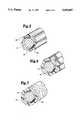
- FIG. 3is a cross sectional view of the guide wire of FIG. 1 taken along line a--a according to a first embodiment of the present invention.
- FIG. 4is a cross sectional view of the guide wire of FIG. 1 taken along line a--a according to a second embodiment of the present invention.
- FIG. 5is a cross sectional view of the guide wire of FIG. 1 taken along line a--a according to a third embodiment of the present invention.
- FIG. 6is a cross sectional view of the guide wire of FIG. 1 taken along line a--a according to a fourth embodiment of the present invention.
- FIG. 7is a cross sectional view of the guide wire of FIG. 1 taken along line a--a according to a fifth embodiment of the present invention.
- FIG. 8illustrates an example of a first type of over-the-wire catheter.
- FIG. 9is a cross sectional view of the catheter of FIG. 8 taken along line 9--9.
- FIG. 10illustrates an example of a second type of over-the-wire catheter.
- FIG. 11is a cross sectional view of the catheter of FIG. 10 taken along line 11--11.
- FIG. 12is a schematic of an extruder.
- FIG. 13illustrates a cross-sectional view of a guide wire having a smooth exterior surface in a lumen.
- FIG. 14illustrates a cross-sectional view of a guide wire according to the present invention in a lumen.
- FIG. 1illustrates a cross-sectional view of a guide wire 10 according to the present invention.
- the guide wire 10is designed preferably for intravascular use and more preferably for percutaneous transluminal coronary angioplasty (PTCA).
- This guide wirehas a proximal end 11 and a distal end 13.
- the guide wire 10includes a core member 12, a coil spring 14, a bridge member 16 and a sleeve member 18.
- the core member 12is formed of stainless steel and has a proximal portion of substantially uniform diameter and a distal portion of reduced and tapered diameters.
- Other materials, including metals such as nitinol which are strong yet flexiblemay be used alone or in combination with other materials.
- the reduced and tapered diameters in the distal portion of the core member 12provide greater flexibility to the distal portion of the guide wire 10. More specifically, the degree of flexibility in the distal portion of the guide wire 10 is determined by the number of tapers and the length and degree of each taper of the core member 12. The most distal portion of the core member 12 is flattened, i.e., preferably tapered from a circular cross-section to a rectangular or ribbon cross-section. The dimensions of the core member 12 as well as the dimensions of other parts of the guide wire 10 will be described in detail hereinafter.
- the coil spring 14surrounds the distal most portion of the core member 12.
- the coil spring 14is composed of a radiopaque material and, most preferably, the coil spring 14 is composed of a platinum alloy having 92% platinum and 8% tungsten.
- the distal end of the coil spring 14is connected to the distal end of the core member 12 by a ball weld 20 that forms a rounded distal tip. Other methods such as soldering may also be used to connect the distal end of the coil spring 14 to the distal end of the core member 12.
- the sleeve member 18surrounds a distal portion of the core member 12 proximal of the coil spring 14.
- the sleeve member 18is positioned proximal to the coil spring 14 so that the distal end of the sleeve member 18 abuts the proximal end of the coil spring 14.
- the distal end of the sleeve member 18 and the proximal end of the coil spring 14have substantially equal outer diameters so as to form a smooth transition between them.
- the sleeve member 18is composed of a blend of nylon and polyether or polyether block amide, commercially available under the tradename PEBAX from Autochem of Birdsboro, Pa. Other materials such as polyester, polyurethane, polyimide and polytetrafluoroethylene (PTFE), for example may be used.
- the bridge member 16is located around the core member 12 under the distal end of the sleeve member 18 and the proximal end of the coil spring 14.
- the bridge member 16is a small cylindrical hypotube of 304 stainless steel that fits around a portion of the core member 12.
- the outer diameter of the bridge member 16corresponds to the inner diameters of the sleeve member 18 and the coil spring 14 as will be described in detail hereinafter.
- the bridge member 16facilitates the alignment between the sleeve member 18 and the coil spring 14 over the core member 12.
- the guide wire 10may be constructed in various sizes to accommodate the specific environment in which it will be used.
- the guide wire 10will have an overall outer diameter of either 0.014 or 0.018 inches (0.36 mm or 0.46 mm) and an overall length of about 74.8 inches (190 cm).
- the dimensions of the guide wire 10 having a diameter of about 0.014 inches (0.36 mm)will be described first. The following dimensional information is for illustration purposes and is not intended as a limitation of the preferred embodiments of the present invention.
- Guide wires having other dimensionsmay be constructed according to the present invention, in particular, smaller guide wires, for example, guide wires having a diameter of about 0.009 inches (0.23 mm) may be constructed.
- the core member 12has several tapers along its length.
- the tapers in the core member 12are separated by regions of the core member 12 having a constant diameter.
- a first region (r 1 ) having a length of about 60 inches (152.4 cm)the diameter of the core member 12 is about 0.0138 inches (0.351 mm).
- Adjacent to the first region (r 1 )is a first taper (t 1 ) having a length of about 0.7 to about 1.3 inches (17.78 to 33.02 mm).
- the diameter of the core member 12is reduced from the diameter of the first region (r 1 ), about 0.0138 inches (0.351 mm), to a diameter ranging from about 0.0064 to about 0.007 inches (0.1626 to 0.178 mm).
- Adjacent to the first taper (t 1 )is a second region (r 2 ) having a length of about 6.75 to about 7.75 inches (17.15 to 19.69 mm) and a diameter of about 0.0064 to about 0.007 inches (0.1626 to 0.0178 mm).
- Adjacent to second region (r 2 )is a second taper (t 2 ) having a length of about 0.7 to 1.3 inches (17.78 to 33.02 mm).
- the diameter of the core member 12is reduced from the diameter of the second region (r 2 ), about 0.0064 to about 0.007 inches (0.1626 to 0.178 mm), to a diameter of about 0.0052 to about 0.0058 inches (0.132 to 0.147 mm).
- Adjacent to the second taper (t 2 )is a third region (r 3 ) having a length of about 1.50 inches (38.1 mm) and a diameter of about 0.0042 to about 0.0058 inches (0.132 to 0.147 mm).
- Adjacent to third region (r 3 )is a third taper (t 3 ) having a length of about 1.73 to about 1.77 inches (43.9 to 44.9 mm).
- the diameter of the core wire 10is reduced from the diameter of the third region (r 3 ), about 0.0058 inches (0.132 to 0.147 mm), to a diameter of about 0.0023 to about 0.0027 inches (0.058 to 0.069 mm).
- There is a further reduction of the core wireaccomplished by forming a ribbon having a flattened cross-section having a thickness of about 0.001 inches (0.026 mm) and a width of about 0.005 inches (0.13 mm) as will be described with reference to FIG. 2.
- FIG. 2illustrates a cross sectional view of the guide wire of FIG. 1 taken along line 2--2.
- the flattened portionhas a length of about 0.48 to about 0.52 inches (12.2 to 13.2 mm), a thickness (t) of about 0.0009 to about 0.0013 inches (0.023 to 0.033 mm) and a width of about 0.005 inches (0.13 mm).
- the various regions of the core wire having tapers and sections of uniform cross sectionmay be formed by methods known in the art, such as chemical washes, polishes, grinding or compressing for example.
- the coil spring 14has a length of about 1.33 to about 1.43 inches (33.78 to 36.32 mm).
- the coil spring 14is constructed of a wire having a diameter of about 0.0027 to about 0.0033 inches (0.069 to 0.084 mm) wound to form a coil having a pitch of about 0.0041 to about 0.0049 inches (0.104 to 0.125 mm).
- the coil spring 14is formed of a platinum alloy wire having 92% platinum and 8% tungsten.
- the bridge member 16has a length of about 0.03 inches (0.76 mm), an outer diameter of about 0.0075 to about 0.0081 inches (0.19 to 0.21 mm) and an inner diameter of about 0.006 inches (0.15 mm). As previously described, the bridge member 16 is formed of 304 stainless steel. The sleeve member 18 will be described in detail with reference to FIGS. 3-7.
- the diameter of the first region (r 1 )is about 0.0178 inches (0.452 mm)
- the diameter of the second region (r 2 )is about 0.0092 to about 0.0098 inches (0.234 to 0.249 mm).
- the distal end of the guide wire 10has a diameter ranging from about 0.0175 to about 0.0185 inches (0.446 to 0.47 mm) and the bridge member 16 has an outer diameter of about 0.0115 to about 0.0121 inches (0.29 to 0.31 mm).
- the sleeve member 18has a length of about 10.5 to 11.0 inches (26.7 to 27.9 mm) and an inner diameter of about 0.009 inches (0.23 mm).
- the exterior surface profile of the sleeve member 18is unsmooth as will be described with reference to FIGS. 3-7.
- the sleeve member 18has a variable outer diameter which may range from a maximum outer diameter of about 0.014 inches (0.36 mm) and a minimum outer diameter of about 0.012 inches (0.30 mm).
- FIG. 3is a cross sectional view of the guide wire 10 of FIG. 1 taken along line a--a according to a first embodiment of the present invention.
- the unsmooth exterior surface 22 of the sleeve member 18is created by ribs or nubs 24 formed on the exterior surface 22 of the sleeve member 18.
- the number of ribs 24 formed on the exterior surface 22 of the sleeve member 18is determined by the surface area of the sleeve member 18 and the footprint of each rib 24.
- the number of ribs located around the periphery of the sleeve member 18may range from four (4) to about sixteen (16).
- the sleeve member 18is preferably constructed of an extrudable material.
- the sleeve memberis constructed by extruding the sleeve material through a die having a configuration or shape complementary to the exterior of the sleeve member 18 so that when the sleeve material is extruded through the die, ribs 24 are formed on its exterior surface 22.
- the inner surface 26 of the sleeve member 18is smooth and preferably circular in cross-section.
- FIG. 12is a schematic of an extruder used to create a sleeve member according to the present invention.
- the extruderincludes a hopper 50, a barrel 52, a first clamp ring 54 and a second clamp ring 56, a melt pump 58, a melt filter 60 and die 62.
- Temperature controllers(not shown) are used to control the temperatures in the various zones of the extruder.
- zone 1is set to a temperature of about 351° F.
- zone 2is set to about 354° F.
- zone 3is set to about 364° F.
- zone 4is set to about 400° F.
- zone 5is set to about 409° F.
- zone 6is set to about 409° F.
- zone 7is set to about 412° F.
- the extruder screw(not shown) is activated preferably at 4.5 revolutions per minute (rpm).
- Sleeve materialis added to the hopper 50.
- the inlet pressure to the melt pump 58is observed and once has increased from about 500 to about 1,000 psi, the melt pump 58 can be started.
- the pump 58is started at about 2 rpm plus or minus 1 rpm.
- the pump 58is run for about 10 to 15 minutes at this speed. Its speed can then be increased to about 15-20 rpm to fill the melt filter 60 with sleeve material.
- the melt pump 58 speedis adjusted to obtain a desired die pressure and output which will be explained in detail hereinafter.
- a puller and cutter assembly(not shown) is turned on and the speed of the puller is set to a reasonable speed so that when the extruded tubing goes into the puller it does not break off from the die face as is well known to those of ordinary skill in the art.
- the speedis set to approximately 125 feet per minute.
- the pullerpulls the extruded tubing through a water bath positioned between the die face and the puller immediately after the die. The tubing extruded is then measured and if necessary adjustments are made in the puller speed.
- FIG. 4is a cross sectional view of the guide wire 10 of FIG. 1 taken along line a--a according to a second embodiment of the present invention.
- the sleeve member 18 of FIG. 4is similar to that illustrated in FIG. 3, however, the ribs 24 do not extend longitudinally parallel to the longitudinal axis of the core member 12. Rather the ribs 24 form spirals along the exterior surface 22 of the sleeve member 18.
- the sleeve materialis extruded through a die having the same shape as described with reference to FIG. 3 except the tubing or die is spun or twisted as it is extruded.
- FIG. 5is a cross sectional view of the guide wire 10 of FIG. 1 taken along line a--a according to a third embodiment of the present invention.
- the cross section of the exterior surface of the sleeve member 18is polygonal. Preferably the corners 28 of the polygon are rounded. In a most preferred embodiment, the cross section of the sleeve member 18 is octagonal with rounded corners.
- the sleeve member 18 according to this preferred embodimentis also formed by extruding the sleeve material through a die having a configuration complementary to the exterior surface of the sleeve member 18.
- FIG. 6is a cross sectional view of the guide wire 10 of FIG. 1 taken along line a--a according to a fourth embodiment of the present invention.
- the sleeve member 18 of FIG. 6is similar to that illustrated in FIG. 5 with the exception that the corners of the polygon are more rounded than those of FIG. 5. This can be accomplished by selecting a die having a configuration complementary to the exterior surface of the sleeve as previously described with reference to the other preferred embodiments or, the corners can be formed by extruding a sleeve member having the shape illustrated in FIG. 5 and then buffing the corners so that they become more rounded.
- FIG. 7is a cross sectional view of the guide wire 10 of FIG. 1 taken along line a--a according to a fifth embodiment of the present invention.
- the sleeve member 18is constructed from a piece of tubing initially having a smooth exterior surface 22. The exterior surface is then altered so that it becomes unsmooth. This may be accomplished by several methods. For example, an abrasive material may be rubbed along the exterior surface to form grooves in the surface of the sleeve member 18. Or the tubing may be placed in a cryogenic tumbler which causes the exterior surface to become unsmooth.
- the sleeve materialmay be extruded through a die having a smooth and preferably circular cross section but, as the tubing is extruded, air may be blown at the tubing thereby causing its surface to become unsmooth.
- the temperature of the extrudermay be altered so that the outside surface of the extruded tube hardens before its inner surface thereby causing the exterior surface profile of the tubing to become irregular.
- the construction of the guide wire 10 shown in FIG. 1will now be described.
- the sleeve member 18is loaded on the core member 12 and slid proximally.
- the bridge member 16 and coil spring 14are then loaded on the core member 12.
- a weldis then formed at the distal end of the core member 12 to bond the distal end of the coil spring 14 with the distal end of the core wire and also to form the rounded tip 20. Forming such a weld is well known to those skilled in the art and this need not be described in detail.
- the rounded distal end 20will have a diameter ranging from about 0.0135 to about 0.0145 inches (0.228 to 0.368 mm).
- the bridge member 16is then positioned half way under the coil spring 14 and the coil spring 14 and bridge member 16 are soldered to the core member 12.
- the sleeve member 18is then slid distally over the exposed half on the bridge member 16 and then bonded to the bridge member 16 at its distal end and the core member at its proximal end with LOCTITE 405 cyanoacrylate available from Loctite Corporation of Newington, Conn.
- a coatingmay be applied to the distal 12 to 18 inches (40.6 to 45.7 cm) of the guide wire 10 approximately corresponding to the sleeve member 18 and the coil spring 14.
- the coatingis composed of silicon oil and a modified moisture curable polydimethylsiloxane used on some commercially available devices sold by SciMed Life Systems, Inc., the assignee of the present invention, known under the tradename XTRA.
- the coatingprovides a uniform, low friction surface along the distal portion of the guide wire 10.
- a coating of low friction materialis applied, preferably Teflon.
- the low friction coatingextends substantially the entire length of the proximal core member 12 from about 1.0 inch (25.4 mm) of the proximal end of the sleeve member 18 to within about 1.0 inch (25.4 mm) of the proximal end of the core member 12.
- FIGS. 8 and 10illustrate examples of two catheters that may be used with the guide wire 10 of the preferred embodiments.
- FIG. 8illustrates an example of a first type of over-the-wire catheter.
- the catheter 30has a guide wire lumen 32 provided by inner tubular member 34.
- the guide wire lumenhas a smooth circular cross section extending along its length as can be seen in FIG. 9 which is a cross-sectional view of the catheter of FIG. 8 taken along line 9--9.
- the catheteris conventional in design and thus need not be described in greater detail.
- FIG. 10illustrates an example of a second type of over-the-wire catheter.
- the catheter 40has a guide wire lumen 42 which preferably has a smooth circular cross section as can be seen in FIG. 11 which is a cross sectional view of the catheter of FIG. 10 taken along line 11--11.
- the catheter 40is conventional in design and thus need not be described in greater detail.
- One suitable catheter which may be used with the guide wire of the present inventionis commercially available under the tradename COBRA from SciMed Life Systems, Inc.
- the guide wire 10 of the presently preferred embodimentshas an unsmooth surface profile on at least a portion of its exterior so that when it is located within the guide wire lumen of the catheter 30 the exterior surface of the sleeve member 18 makes limited contact with the guide wire lumen wall. More specifically, the points of contact are made by the raised surface areas of the sleeve member 18 such as the ribs of FIGS. 3 and 4, the corner 28 of FIGS. 5 and 6 or the crests of the grooves of FIG. 7.
- the points of contact between the exterior surface of the sleeve member 18 and the guide wire lumen wallare less than would be the case if the exterior surface of the guide wire 10 were smooth, such as if it had a circular cross section, the amount of friction between the guide wire 10 and the guide wire lumen is reduced.
- FIG. 13illustrates a cross-sectional view of wire 70 having a smooth exterior surface in a lumen 72 such as the guide wire lumen of a catheter.
- the catheterbends as it travels through passageways, such as blood vessels, in the body thereby bringing the exterior of the guide wire in contact with the guide wire lumen wall 73 as shown in FIG. 13. Because the exterior surface of the guide wire is smooth, a large surface area of the guide wire contacts the guide wire lumen wall.
- FIG. 14illustrates a cross-sectional view of a guide wire 74 according to the present invention in a guide wire lumen 76 of a catheter.
- the raised surfaces 78limit the amount of contact between the exterior surface area of the guide wire 74 and the guide wire lumen wall 77.
- the guide wire according to the present inventionreduces the amount of surface area contact between the exterior of the guide wire and the guide wire lumen wall.
- the sleeve according to the inventionmay be extended over a greater length of the core wire than illustrated in the preferred embodiments. In fact, the sleeve member could extend substantially the entire length of the core member if desired.
Landscapes
- Health & Medical Sciences (AREA)
- Life Sciences & Earth Sciences (AREA)
- Biophysics (AREA)
- Pulmonology (AREA)
- Engineering & Computer Science (AREA)
- Anesthesiology (AREA)
- Biomedical Technology (AREA)
- Heart & Thoracic Surgery (AREA)
- Hematology (AREA)
- Animal Behavior & Ethology (AREA)
- General Health & Medical Sciences (AREA)
- Public Health (AREA)
- Veterinary Medicine (AREA)
- Media Introduction/Drainage Providing Device (AREA)
Abstract
Description
Claims (7)
Priority Applications (1)
| Application Number | Priority Date | Filing Date | Title |
|---|---|---|---|
| US08/147,724US5404887A (en) | 1993-11-04 | 1993-11-04 | Guide wire having an unsmooth exterior surface |
Applications Claiming Priority (1)
| Application Number | Priority Date | Filing Date | Title |
|---|---|---|---|
| US08/147,724US5404887A (en) | 1993-11-04 | 1993-11-04 | Guide wire having an unsmooth exterior surface |
Publications (1)
| Publication Number | Publication Date |
|---|---|
| US5404887Atrue US5404887A (en) | 1995-04-11 |
Family
ID=22522663
Family Applications (1)
| Application Number | Title | Priority Date | Filing Date |
|---|---|---|---|
| US08/147,724Expired - LifetimeUS5404887A (en) | 1993-11-04 | 1993-11-04 | Guide wire having an unsmooth exterior surface |
Country Status (1)
| Country | Link |
|---|---|
| US (1) | US5404887A (en) |
Cited By (82)
| Publication number | Priority date | Publication date | Assignee | Title |
|---|---|---|---|---|
| US5673707A (en)* | 1994-09-23 | 1997-10-07 | Boston Scientific Corporation | Enhanced performance guidewire |
| US5722424A (en)* | 1995-09-29 | 1998-03-03 | Target Therapeutics, Inc. | Multi-coating stainless steel guidewire |
| US5746701A (en)* | 1995-09-14 | 1998-05-05 | Medtronic, Inc. | Guidewire with non-tapered tip |
| US5762631A (en)* | 1995-07-14 | 1998-06-09 | Localmed, Inc. | Method and system for reduced friction introduction of coaxial catheters |
| US5797856A (en)* | 1995-01-05 | 1998-08-25 | Cardiometrics, Inc. | Intravascular guide wire and method |
| US5827201A (en)* | 1996-07-26 | 1998-10-27 | Target Therapeutics, Inc. | Micro-braided guidewire |
| US5987352A (en)* | 1996-07-11 | 1999-11-16 | Medtronic, Inc. | Minimally invasive implantable device for monitoring physiologic events |
| US6039699A (en)* | 1996-01-22 | 2000-03-21 | Cordis Corporation | Stiff catheter guidewire with flexible distal portion |
| US6102874A (en)* | 1998-05-13 | 2000-08-15 | Medtronic, Inc. | Implantable medical device for tracking patient functional status |
| US6106485A (en)* | 1997-11-18 | 2000-08-22 | Advanced Cardivascular Systems, Inc. | Guidewire with shaped intermediate portion |
| US6113557A (en)* | 1997-06-20 | 2000-09-05 | Medtronic Ave, Inc. | Variable stiffness angioplasty guide wire |
| US6206834B1 (en)* | 1995-06-29 | 2001-03-27 | Schneider (Europe) A.G. | Stiffened hollow vascular device |
| US6236882B1 (en) | 1999-07-14 | 2001-05-22 | Medtronic, Inc. | Noise rejection for monitoring ECG's |
| US6336906B1 (en)* | 1998-12-23 | 2002-01-08 | Radi Medical Systems Ab | Sensor and guide wire assembly |
| US6347245B1 (en) | 1999-07-14 | 2002-02-12 | Medtronic, Inc. | Medical device ECG marker for use in compressed data system |
| US6454702B1 (en)* | 1999-10-14 | 2002-09-24 | Scimed Life Systems, Inc. | Endoscope and endoscopic instrument system having reduced backlash when moving the endoscopic instrument within a working channel of the endoscope |
| US20020165580A1 (en)* | 2001-05-03 | 2002-11-07 | Aaron Zwiefel | Biopsy forceps device with transparent outer sheath |
| US6496715B1 (en) | 1996-07-11 | 2002-12-17 | Medtronic, Inc. | System and method for non-invasive determination of optimal orientation of an implantable sensing device |
| US6517539B1 (en) | 1999-08-06 | 2003-02-11 | Scimed Life Systems, Inc. | Polypectomy snare having ability to actuate through tortuous path |
| US6537205B1 (en)* | 1999-10-14 | 2003-03-25 | Scimed Life Systems, Inc. | Endoscopic instrument system having reduced backlash control wire action |
| US20030125731A1 (en)* | 1999-08-06 | 2003-07-03 | Scimed Life Systems, Inc. | Polypectomy snare having ability to actuate through tortuous path |
| US6596020B2 (en) | 1996-11-04 | 2003-07-22 | Advanced Stent Technologies, Inc. | Method of delivering a stent with a side opening |
| US20030181923A1 (en)* | 1996-11-04 | 2003-09-25 | Gil Vardi | Methods for deploying stents in bifurcations |
| US20030195606A1 (en)* | 1999-09-23 | 2003-10-16 | Advanced Stent Technologies, Inc., A Delaware Corporation | Bifurcation stent system and method |
| US6673025B1 (en) | 1993-12-01 | 2004-01-06 | Advanced Cardiovascular Systems, Inc. | Polymer coated guidewire |
| US6682536B2 (en) | 2000-03-22 | 2004-01-27 | Advanced Stent Technologies, Inc. | Guidewire introducer sheath |
| US6689156B1 (en) | 1999-09-23 | 2004-02-10 | Advanced Stent Technologies, Inc. | Stent range transducers and methods of use |
| US6689151B2 (en)* | 2001-01-25 | 2004-02-10 | Scimed Life Systems, Inc. | Variable wall thickness for delivery sheath housing |
| US6692483B2 (en) | 1996-11-04 | 2004-02-17 | Advanced Stent Technologies, Inc. | Catheter with attached flexible side sheath |
| US6743206B1 (en) | 2000-03-07 | 2004-06-01 | Syntheon, Llc | Endoscopic needle |
| US20040133268A1 (en)* | 1998-01-14 | 2004-07-08 | Advanced Stent Technologies, Inc. | Extendible stent apparatus |
| US6761717B2 (en) | 1999-10-15 | 2004-07-13 | Scimed Life Systems, Inc. | Multifilar flexible rotary shaft and medical instruments incorporating the same |
| US20040151882A1 (en)* | 2002-09-26 | 2004-08-05 | Fujitsu Limited | Wiring board with core layer containing inorganic filler |
| US20040167439A1 (en)* | 2003-02-26 | 2004-08-26 | Sharrow James S. | Guidewire having textured proximal portion |
| US6835203B1 (en) | 1996-11-04 | 2004-12-28 | Advanced Stent Technologies, Inc. | Extendible stent apparatus |
| US6884258B2 (en) | 1999-06-04 | 2005-04-26 | Advanced Stent Technologies, Inc. | Bifurcation lesion stent delivery using multiple guidewires |
| US20050113845A1 (en)* | 2003-11-20 | 2005-05-26 | Scimed Life Systems, Inc. | Self-orienting polypectomy snare device |
| US20050245941A1 (en)* | 1999-12-06 | 2005-11-03 | Vardi Gil M | Catheter with attached flexible side sheath |
| US6962602B2 (en) | 1996-11-04 | 2005-11-08 | Advanced Stent Tech Llc | Method for employing an extendible stent apparatus |
| US20060073264A1 (en)* | 2002-09-20 | 2006-04-06 | I.S.T Corporation | Medical guide wire and process for production thereof |
| US20060116602A1 (en)* | 2004-12-01 | 2006-06-01 | Alden Dana A | Medical sensing device and system |
| EP1685870A1 (en)* | 2005-01-31 | 2006-08-02 | Cordis Corporation | Guidewire with superelastic core |
| US7220275B2 (en) | 1996-11-04 | 2007-05-22 | Advanced Stent Technologies, Inc. | Stent with protruding branch portion for bifurcated vessels |
| US20070135904A1 (en)* | 2005-12-14 | 2007-06-14 | Tracee Eidenschink | Telescoping bifurcated stent |
| US20070135903A1 (en)* | 2005-12-14 | 2007-06-14 | Daniel Gregorich | Connectors for bifurcated stent |
| US20070149951A1 (en)* | 2005-12-27 | 2007-06-28 | Mina Wu | Variable stiffness guidewire |
| US20070208414A1 (en)* | 2006-03-06 | 2007-09-06 | Shawn Sorenson | Tapered strength rings on a bifurcated stent petal |
| US20070225554A1 (en)* | 2006-03-22 | 2007-09-27 | Boston Scientific Scimed, Inc. | Endoscope working channel with multiple functionality |
| US20070233233A1 (en)* | 2006-03-31 | 2007-10-04 | Boston Scientific Scimed, Inc | Tethered expansion columns for controlled stent expansion |
| US20070255217A1 (en)* | 2003-09-16 | 2007-11-01 | Abbott Cardiovascular Systems Inc. | Textured polymer coated guide wire and method of manufacture |
| US20080021405A1 (en)* | 2002-07-25 | 2008-01-24 | Precision Vascular Systems, Inc. | Medical device for navigation through anatomy and method of making same |
| US7341598B2 (en) | 1999-01-13 | 2008-03-11 | Boston Scientific Scimed, Inc. | Stent with protruding branch portion for bifurcated vessels |
| US7344557B2 (en) | 2003-11-12 | 2008-03-18 | Advanced Stent Technologies, Inc. | Catheter balloon systems and methods |
| US20080146967A1 (en)* | 1997-06-04 | 2008-06-19 | Richardson Mark T | Polymer coated guidewire |
| US20080228109A1 (en)* | 2007-03-14 | 2008-09-18 | Terumo Kabushiki Kaisha | Guide wire |
| US7455646B2 (en) | 1997-06-04 | 2008-11-25 | Advanced Cardiovascular Systems, Inc. | Polymer coated guide wire |
| US20100004561A1 (en)* | 2008-06-30 | 2010-01-07 | Terumo Kabushiki Kaisha | Guide wire |
| US7655030B2 (en) | 2003-07-18 | 2010-02-02 | Boston Scientific Scimed, Inc. | Catheter balloon systems and methods |
| US7766955B2 (en) | 1996-11-04 | 2010-08-03 | Boston Scientific Scimed, Inc. | Extendible stent apparatus |
| US7846171B2 (en) | 2004-05-27 | 2010-12-07 | C.R. Bard, Inc. | Method and apparatus for delivering a prosthetic fabric into a patient |
| US20110071423A1 (en)* | 2009-09-21 | 2011-03-24 | Speeg Trevor W V | Flexible biopsy marker delivery device |
| US20110152791A1 (en)* | 2008-08-11 | 2011-06-23 | Terumo Kabushiki Kaisha | Medical instrument |
| US20110288624A1 (en)* | 2010-05-24 | 2011-11-24 | Roeder Blayne A | Variable diameter trigger wire |
| US20120197159A1 (en)* | 2011-01-28 | 2012-08-02 | Asahi Intecc Co., Ltd. | Guidewire |
| US8298280B2 (en) | 2003-08-21 | 2012-10-30 | Boston Scientific Scimed, Inc. | Stent with protruding branch portion for bifurcated vessels |
| US20130006149A1 (en)* | 2011-06-29 | 2013-01-03 | Abbott Cardiovascular Systems | Guide Wire Device Including a Solderable Linear Elastic Nickel-Titanium Distal End Section and Methods Of Preparation Therefor |
| US8377108B2 (en) | 2008-06-02 | 2013-02-19 | Boston Scientific Scimed, Inc. | Staggered two balloon bifurcation catheter assembly and methods |
| US20130053844A1 (en)* | 2011-03-02 | 2013-02-28 | Olympus Medical Systems Corp. | Treatment instrument for endoscope |
| US8486134B2 (en) | 2007-08-01 | 2013-07-16 | Boston Scientific Scimed, Inc. | Bifurcation treatment system and methods |
| US8617231B2 (en) | 2001-05-18 | 2013-12-31 | Boston Scientific Scimed, Inc. | Dual guidewire exchange catheter system |
| US20140103273A1 (en)* | 2011-06-13 | 2014-04-17 | Nissei Electric Co., Ltd. | Resin Tube for Guide Wire, Method for Manufacturing Resin Tube for Guide Wire, and Guide Wire |
| US8747456B2 (en) | 2007-12-31 | 2014-06-10 | Boston Scientific Scimed, Inc. | Bifurcation stent delivery system and methods |
| US8821561B2 (en) | 2006-02-22 | 2014-09-02 | Boston Scientific Scimed, Inc. | Marker arrangement for bifurcation catheter |
| US8827954B2 (en) | 2008-06-05 | 2014-09-09 | Boston Scientific Scimed, Inc. | Deflatable bifurcated device |
| US8936567B2 (en) | 2007-11-14 | 2015-01-20 | Boston Scientific Scimed, Inc. | Balloon bifurcated lumen treatment |
| US20170043119A1 (en)* | 2015-08-10 | 2017-02-16 | Asahi Intecc Co., Ltd. | Catheter and balloon catheter |
| JP2017209419A (en)* | 2016-05-27 | 2017-11-30 | 朝日インテック株式会社 | Guide wire |
| US10603067B2 (en) | 2016-07-28 | 2020-03-31 | Boston Scientific Scimed, Inc. | Polypectomy snare devices |
| JPWO2022070424A1 (en)* | 2020-10-02 | 2022-04-07 | ||
| US11452533B2 (en) | 2019-01-10 | 2022-09-27 | Abbott Cardiovascular Systems Inc. | Guide wire tip having roughened surface |
| US11779477B2 (en) | 2010-11-17 | 2023-10-10 | Abbott Cardiovascular Systems, Inc. | Radiopaque intraluminal stents |
| US12151049B2 (en) | 2019-10-14 | 2024-11-26 | Abbott Cardiovascular Systems, Inc. | Methods for manufacturing radiopaque intraluminal stents comprising cobalt-based alloys with supersaturated tungsten content |
Citations (20)
| Publication number | Priority date | Publication date | Assignee | Title |
|---|---|---|---|---|
| US3452742A (en)* | 1966-05-31 | 1969-07-01 | Us Catheter & Instr Corp | Controlled vascular curvable spring guide |
| US3731671A (en)* | 1971-10-21 | 1973-05-08 | Cordis Corp | Low-friction catheter guide |
| US3973556A (en)* | 1975-06-20 | 1976-08-10 | Lake Region Manufacturing Company, Inc. | Smoothened coil spring wire guide |
| US4080706A (en)* | 1975-04-22 | 1978-03-28 | Medrad, Inc. | Method of manufacturing catheter guidewire |
| GB2017182A (en)* | 1978-03-28 | 1979-10-03 | Fresenius Chem Pharm Ind | Stuffenig core for catheters |
| US4257421A (en)* | 1979-01-10 | 1981-03-24 | Health Development Corporation | Gastro-intestinal tube guide and stiffener |
| US4430083A (en)* | 1981-03-06 | 1984-02-07 | American Hospital Supply Corporation | Infusion catheter |
| US4534363A (en)* | 1982-04-29 | 1985-08-13 | Cordis Corporation | Coating for angiographic guidewire |
| US4579127A (en)* | 1983-08-02 | 1986-04-01 | Intermedicat Gmbh | Mandrel for hose type catheters and body probes |
| US4682607A (en)* | 1985-12-02 | 1987-07-28 | Vlv Associates | Wire guide |
| US4811743A (en)* | 1987-04-21 | 1989-03-14 | Cordis Corporation | Catheter guidewire |
| US4884579A (en)* | 1988-04-18 | 1989-12-05 | Target Therapeutics | Catheter guide wire |
| US5107852A (en)* | 1990-04-02 | 1992-04-28 | W. L. Gore & Associates, Inc. | Catheter guidewire device having a covering of fluoropolymer tape |
| US5122125A (en)* | 1990-04-25 | 1992-06-16 | Ashridge A.G. | Catheter for angioplasty with soft centering tip |
| US5125909A (en)* | 1989-06-14 | 1992-06-30 | Richard Wolf Gmbh | Flexible tubular channel with external supporting ridges |
| US5147317A (en)* | 1990-06-04 | 1992-09-15 | C.R. Bard, Inc. | Low friction varied radiopacity guidewire |
| US5147316A (en)* | 1990-11-19 | 1992-09-15 | Castillenti Thomas A | Laparoscopic trocar with self-locking port sleeve |
| WO1993004722A2 (en)* | 1991-09-05 | 1993-03-18 | Mayo Foundation For Medical Education And Research | Flexible tubular device for use in medical applications |
| US5228453A (en)* | 1991-05-07 | 1993-07-20 | Target Therapeutics, Inc. | Catheter guide wire |
| US5258003A (en)* | 1992-06-01 | 1993-11-02 | Conmed Corporation | Method and apparatus for induction of pneumoperitoneum |
- 1993
- 1993-11-04USUS08/147,724patent/US5404887A/ennot_activeExpired - Lifetime
Patent Citations (21)
| Publication number | Priority date | Publication date | Assignee | Title |
|---|---|---|---|---|
| US3452742A (en)* | 1966-05-31 | 1969-07-01 | Us Catheter & Instr Corp | Controlled vascular curvable spring guide |
| US3731671A (en)* | 1971-10-21 | 1973-05-08 | Cordis Corp | Low-friction catheter guide |
| US4080706A (en)* | 1975-04-22 | 1978-03-28 | Medrad, Inc. | Method of manufacturing catheter guidewire |
| US3973556A (en)* | 1975-06-20 | 1976-08-10 | Lake Region Manufacturing Company, Inc. | Smoothened coil spring wire guide |
| GB2017182A (en)* | 1978-03-28 | 1979-10-03 | Fresenius Chem Pharm Ind | Stuffenig core for catheters |
| US4362163A (en)* | 1978-03-28 | 1982-12-07 | Eduard Fresenius Chem.-Pharm. Industrie Kg Apparatebau Kg | Stiffening core for catheters |
| US4257421A (en)* | 1979-01-10 | 1981-03-24 | Health Development Corporation | Gastro-intestinal tube guide and stiffener |
| US4430083A (en)* | 1981-03-06 | 1984-02-07 | American Hospital Supply Corporation | Infusion catheter |
| US4534363A (en)* | 1982-04-29 | 1985-08-13 | Cordis Corporation | Coating for angiographic guidewire |
| US4579127A (en)* | 1983-08-02 | 1986-04-01 | Intermedicat Gmbh | Mandrel for hose type catheters and body probes |
| US4682607A (en)* | 1985-12-02 | 1987-07-28 | Vlv Associates | Wire guide |
| US4811743A (en)* | 1987-04-21 | 1989-03-14 | Cordis Corporation | Catheter guidewire |
| US4884579A (en)* | 1988-04-18 | 1989-12-05 | Target Therapeutics | Catheter guide wire |
| US5125909A (en)* | 1989-06-14 | 1992-06-30 | Richard Wolf Gmbh | Flexible tubular channel with external supporting ridges |
| US5107852A (en)* | 1990-04-02 | 1992-04-28 | W. L. Gore & Associates, Inc. | Catheter guidewire device having a covering of fluoropolymer tape |
| US5122125A (en)* | 1990-04-25 | 1992-06-16 | Ashridge A.G. | Catheter for angioplasty with soft centering tip |
| US5147317A (en)* | 1990-06-04 | 1992-09-15 | C.R. Bard, Inc. | Low friction varied radiopacity guidewire |
| US5147316A (en)* | 1990-11-19 | 1992-09-15 | Castillenti Thomas A | Laparoscopic trocar with self-locking port sleeve |
| US5228453A (en)* | 1991-05-07 | 1993-07-20 | Target Therapeutics, Inc. | Catheter guide wire |
| WO1993004722A2 (en)* | 1991-09-05 | 1993-03-18 | Mayo Foundation For Medical Education And Research | Flexible tubular device for use in medical applications |
| US5258003A (en)* | 1992-06-01 | 1993-11-02 | Conmed Corporation | Method and apparatus for induction of pneumoperitoneum |
Cited By (166)
| Publication number | Priority date | Publication date | Assignee | Title |
|---|---|---|---|---|
| US6673025B1 (en) | 1993-12-01 | 2004-01-06 | Advanced Cardiovascular Systems, Inc. | Polymer coated guidewire |
| US5673707A (en)* | 1994-09-23 | 1997-10-07 | Boston Scientific Corporation | Enhanced performance guidewire |
| US5797856A (en)* | 1995-01-05 | 1998-08-25 | Cardiometrics, Inc. | Intravascular guide wire and method |
| US6206834B1 (en)* | 1995-06-29 | 2001-03-27 | Schneider (Europe) A.G. | Stiffened hollow vascular device |
| EP0843618A4 (en)* | 1995-07-14 | 2000-05-03 | Localmed Inc | Method and system for reduced friction introduction of coaxial catheters |
| US5762631A (en)* | 1995-07-14 | 1998-06-09 | Localmed, Inc. | Method and system for reduced friction introduction of coaxial catheters |
| US5746701A (en)* | 1995-09-14 | 1998-05-05 | Medtronic, Inc. | Guidewire with non-tapered tip |
| US5984878A (en)* | 1995-09-29 | 1999-11-16 | Target Therapeutics, Inc. | Multi-coating stainless steel guidewire |
| US5722424A (en)* | 1995-09-29 | 1998-03-03 | Target Therapeutics, Inc. | Multi-coating stainless steel guidewire |
| US6039699A (en)* | 1996-01-22 | 2000-03-21 | Cordis Corporation | Stiff catheter guidewire with flexible distal portion |
| US5987352A (en)* | 1996-07-11 | 1999-11-16 | Medtronic, Inc. | Minimally invasive implantable device for monitoring physiologic events |
| US6496715B1 (en) | 1996-07-11 | 2002-12-17 | Medtronic, Inc. | System and method for non-invasive determination of optimal orientation of an implantable sensing device |
| US6412490B1 (en) | 1996-07-11 | 2002-07-02 | Medtronic, Inc. | Tool for insertion of implanatable monitoring device and method |
| US5827201A (en)* | 1996-07-26 | 1998-10-27 | Target Therapeutics, Inc. | Micro-braided guidewire |
| US7850725B2 (en) | 1996-11-04 | 2010-12-14 | Boston Scientific Scimed, Inc. | Extendible stent apparatus |
| US6835203B1 (en) | 1996-11-04 | 2004-12-28 | Advanced Stent Technologies, Inc. | Extendible stent apparatus |
| US9561126B2 (en) | 1996-11-04 | 2017-02-07 | Boston Scientific Scimed, Inc. | Catheter with attached flexible side sheath |
| US20090132028A1 (en)* | 1996-11-04 | 2009-05-21 | Advanced Stent Technologies, Inc. | Extendible Stent Apparatus and Method for Deploying the Same |
| US6596020B2 (en) | 1996-11-04 | 2003-07-22 | Advanced Stent Technologies, Inc. | Method of delivering a stent with a side opening |
| US6692483B2 (en) | 1996-11-04 | 2004-02-17 | Advanced Stent Technologies, Inc. | Catheter with attached flexible side sheath |
| US8771342B2 (en) | 1996-11-04 | 2014-07-08 | Boston Scientific Scimed, Inc. | Methods for deploying stents in bifurcations |
| US7591846B2 (en) | 1996-11-04 | 2009-09-22 | Boston Scientific Scimed, Inc. | Methods for deploying stents in bifurcations |
| US7766955B2 (en) | 1996-11-04 | 2010-08-03 | Boston Scientific Scimed, Inc. | Extendible stent apparatus |
| US6962602B2 (en) | 1996-11-04 | 2005-11-08 | Advanced Stent Tech Llc | Method for employing an extendible stent apparatus |
| US20110082533A1 (en)* | 1996-11-04 | 2011-04-07 | Boston Scientific Scimed, Inc. | Extendible Stent Apparatus |
| US7678142B2 (en) | 1996-11-04 | 2010-03-16 | Boston Scientific Scimed, Inc. | Extendible stent apparatus |
| US7220275B2 (en) | 1996-11-04 | 2007-05-22 | Advanced Stent Technologies, Inc. | Stent with protruding branch portion for bifurcated vessels |
| US20030181923A1 (en)* | 1996-11-04 | 2003-09-25 | Gil Vardi | Methods for deploying stents in bifurcations |
| US7494474B2 (en) | 1997-06-04 | 2009-02-24 | Advanced Cardiovascular Systems, Inc. | Polymer coated guidewire |
| US7455646B2 (en) | 1997-06-04 | 2008-11-25 | Advanced Cardiovascular Systems, Inc. | Polymer coated guide wire |
| US20080146967A1 (en)* | 1997-06-04 | 2008-06-19 | Richardson Mark T | Polymer coated guidewire |
| US6113557A (en)* | 1997-06-20 | 2000-09-05 | Medtronic Ave, Inc. | Variable stiffness angioplasty guide wire |
| US6106485A (en)* | 1997-11-18 | 2000-08-22 | Advanced Cardivascular Systems, Inc. | Guidewire with shaped intermediate portion |
| US6296616B1 (en) | 1997-11-18 | 2001-10-02 | Advanced Cardiovascular Systems, Inc. | Guidewire with shaped intermediate portion |
| US20040133268A1 (en)* | 1998-01-14 | 2004-07-08 | Advanced Stent Technologies, Inc. | Extendible stent apparatus |
| US7537609B2 (en) | 1998-01-14 | 2009-05-26 | Boston Scientific Scimed, Inc. | Extendible stent apparatus |
| US8241349B2 (en) | 1998-01-14 | 2012-08-14 | Boston Scientific Scimed, Inc. | Extendible stent apparatus |
| US7892279B2 (en) | 1998-01-14 | 2011-02-22 | Boston Scientific Scimed, Inc. | Extendible stent apparatus |
| US20110153002A1 (en)* | 1998-01-14 | 2011-06-23 | Boston Scientific Scimed, Inc. | Extendible Stent Apparatus |
| US7118593B2 (en) | 1998-01-14 | 2006-10-10 | Advanced Stent Technologies, Inc. | Extendible stent apparatus |
| US6102874A (en)* | 1998-05-13 | 2000-08-15 | Medtronic, Inc. | Implantable medical device for tracking patient functional status |
| US6280409B1 (en) | 1998-05-13 | 2001-08-28 | Medtronic, Inc. | Medical for tracking patient functional status |
| US6336906B1 (en)* | 1998-12-23 | 2002-01-08 | Radi Medical Systems Ab | Sensor and guide wire assembly |
| US7341598B2 (en) | 1999-01-13 | 2008-03-11 | Boston Scientific Scimed, Inc. | Stent with protruding branch portion for bifurcated vessels |
| US7771462B1 (en) | 1999-06-04 | 2010-08-10 | Boston Scientific Scimed, Inc. | Catheter with side sheath and methods |
| US6884258B2 (en) | 1999-06-04 | 2005-04-26 | Advanced Stent Technologies, Inc. | Bifurcation lesion stent delivery using multiple guidewires |
| US6236882B1 (en) | 1999-07-14 | 2001-05-22 | Medtronic, Inc. | Noise rejection for monitoring ECG's |
| US6347245B1 (en) | 1999-07-14 | 2002-02-12 | Medtronic, Inc. | Medical device ECG marker for use in compressed data system |
| US7016721B2 (en) | 1999-07-14 | 2006-03-21 | Medtronic, Inc. | Medical device ECG marker for use in compressed data stream |
| US20020026122A1 (en)* | 1999-07-14 | 2002-02-28 | Medtronic, Inc. | Medical device ECG marker for use in compressed data stream |
| US8506578B2 (en) | 1999-08-06 | 2013-08-13 | Boston Scientific Scimed, Inc. | Polypectomy snare instrument |
| US20060189978A1 (en)* | 1999-08-06 | 2006-08-24 | Scimed Life Systems, Inc. | Polypectomy snare instrument |
| US20050154254A1 (en)* | 1999-08-06 | 2005-07-14 | Smith Kevin W. | Polypectomy snare instrument |
| US20030125731A1 (en)* | 1999-08-06 | 2003-07-03 | Scimed Life Systems, Inc. | Polypectomy snare having ability to actuate through tortuous path |
| US6517539B1 (en) | 1999-08-06 | 2003-02-11 | Scimed Life Systems, Inc. | Polypectomy snare having ability to actuate through tortuous path |
| US6972017B2 (en) | 1999-08-06 | 2005-12-06 | Scimed Life Systems, Inc. | Polypectomy snare having ability to actuate through tortuous path |
| US20060047279A1 (en)* | 1999-08-06 | 2006-03-02 | Scimed Life Systems, Inc. | Polypectomy snare having ability to actuate through tortuous path |
| US8162938B2 (en) | 1999-08-06 | 2012-04-24 | Boston Scientific Scimed, Inc. | Polypectomy snare having ability to actuate through tortuous path |
| US7052495B2 (en) | 1999-08-06 | 2006-05-30 | Scimed Life Systems, Inc. | Polypectomy snare instrument |
| US20040148006A1 (en)* | 1999-09-23 | 2004-07-29 | Davidson Charles J | Stent range transducers and methods of use |
| US6689156B1 (en) | 1999-09-23 | 2004-02-10 | Advanced Stent Technologies, Inc. | Stent range transducers and methods of use |
| US7585317B2 (en) | 1999-09-23 | 2009-09-08 | Boston Scientific Scimed, Inc. | Stent range transducers |
| US20030195606A1 (en)* | 1999-09-23 | 2003-10-16 | Advanced Stent Technologies, Inc., A Delaware Corporation | Bifurcation stent system and method |
| US6881186B2 (en) | 1999-10-14 | 2005-04-19 | Scimed Life Systems, Inc. | Endoscope and endoscopic instrument system having reduced backlash when moving the endoscopic instrument within a working channel of the endoscope |
| US20030083545A1 (en)* | 1999-10-14 | 2003-05-01 | Scimed Life Systems, Inc. | Endoscopic instrument system having reduced backlash control wire action |
| US20060178658A1 (en)* | 1999-10-14 | 2006-08-10 | Scimed Life Systems, Inc. | Endoscope and endoscopic instrument system having reduced backlash when moving the endoscopic instrument within a working channel of the endoscope |
| US20050107668A1 (en)* | 1999-10-14 | 2005-05-19 | Scimed Life Systems, Inc. | Endoscopic instrument system having reduced backlash control wire action |
| US8652028B2 (en) | 1999-10-14 | 2014-02-18 | Boston Scientific Scimed, Inc. | Endoscopic instrument system having reduced backlash control wire action |
| US8678998B2 (en)* | 1999-10-14 | 2014-03-25 | Boston Scientific Scimed, Inc. | Endoscope and endoscopic instrument system having reduced backlash when moving the endoscopic instrument within a working channel of the endoscope |
| US20050107662A1 (en)* | 1999-10-14 | 2005-05-19 | Scimed Life Systems, Inc. | Endoscope and endoscopic instrument system having reduced backlash when moving the endoscopic instrument within a working channel of the endoscope |
| US6537205B1 (en)* | 1999-10-14 | 2003-03-25 | Scimed Life Systems, Inc. | Endoscopic instrument system having reduced backlash control wire action |
| US6840900B2 (en) | 1999-10-14 | 2005-01-11 | Scimed Life Systems, Inc. | Endoscopic instrument system having reduced backlash control wire action |
| US7033315B2 (en) | 1999-10-14 | 2006-04-25 | Scimed Life Systems, Inc. | Endoscope and endoscopic instrument system having reduced backlash when moving the endoscopic instrument within a working channel of the endoscope |
| US6454702B1 (en)* | 1999-10-14 | 2002-09-24 | Scimed Life Systems, Inc. | Endoscope and endoscopic instrument system having reduced backlash when moving the endoscopic instrument within a working channel of the endoscope |
| US7276067B2 (en) | 1999-10-15 | 2007-10-02 | Boston Scientific Scimed, Inc. | Multifilar flexible rotary shaft and medical instruments incorporating the same |
| US20070299428A1 (en)* | 1999-10-15 | 2007-12-27 | Boston Scientific Scimed, Inc. | Multifilar Flexible Rotary Shaft and Medical Instruments Incorporating the Same |
| US8241280B2 (en) | 1999-10-15 | 2012-08-14 | Boston Scientific Scimed, Inc. | Multifilar flexible rotary shaft and medical instruments incorporating the same |
| US6761717B2 (en) | 1999-10-15 | 2004-07-13 | Scimed Life Systems, Inc. | Multifilar flexible rotary shaft and medical instruments incorporating the same |
| US8211167B2 (en) | 1999-12-06 | 2012-07-03 | Boston Scientific Scimed, Inc. | Method of using a catheter with attached flexible side sheath |
| US20050245941A1 (en)* | 1999-12-06 | 2005-11-03 | Vardi Gil M | Catheter with attached flexible side sheath |
| US6743206B1 (en) | 2000-03-07 | 2004-06-01 | Syntheon, Llc | Endoscopic needle |
| US6682536B2 (en) | 2000-03-22 | 2004-01-27 | Advanced Stent Technologies, Inc. | Guidewire introducer sheath |
| US7097652B2 (en) | 2001-01-25 | 2006-08-29 | Scimed Life Systems, Inc. | Variable wall thickness for delivery sheath housing |
| US20040158278A1 (en)* | 2001-01-25 | 2004-08-12 | Scimed Life Systems, Inc. | Variable wall thickness for delivery sheath housing |
| US6689151B2 (en)* | 2001-01-25 | 2004-02-10 | Scimed Life Systems, Inc. | Variable wall thickness for delivery sheath housing |
| US20020165580A1 (en)* | 2001-05-03 | 2002-11-07 | Aaron Zwiefel | Biopsy forceps device with transparent outer sheath |
| US7341564B2 (en) | 2001-05-03 | 2008-03-11 | Boston Scientific Scimed, Inc. | Biopsy forceps device with transparent outer sheath |
| US8617231B2 (en) | 2001-05-18 | 2013-12-31 | Boston Scientific Scimed, Inc. | Dual guidewire exchange catheter system |
| US20080021405A1 (en)* | 2002-07-25 | 2008-01-24 | Precision Vascular Systems, Inc. | Medical device for navigation through anatomy and method of making same |
| US8192373B2 (en) | 2002-09-20 | 2012-06-05 | Seven Dreamers Laboratories, Inc. | Medical guide wire and process for production thereof |
| US20110177230A1 (en)* | 2002-09-20 | 2011-07-21 | I.S.T Corporation | Medical guide wire and process for production thereof |
| US20060073264A1 (en)* | 2002-09-20 | 2006-04-06 | I.S.T Corporation | Medical guide wire and process for production thereof |
| US8162855B2 (en)* | 2002-09-20 | 2012-04-24 | Seven Dreamers Laboratories, Inc. | Medical guide wire and process for production thereof |
| US20040151882A1 (en)* | 2002-09-26 | 2004-08-05 | Fujitsu Limited | Wiring board with core layer containing inorganic filler |
| US20040167439A1 (en)* | 2003-02-26 | 2004-08-26 | Sharrow James S. | Guidewire having textured proximal portion |
| US7655030B2 (en) | 2003-07-18 | 2010-02-02 | Boston Scientific Scimed, Inc. | Catheter balloon systems and methods |
| US8771334B2 (en) | 2003-07-18 | 2014-07-08 | Boston Scientific Scimed, Inc. | Catheter balloon systems and methods |
| US8298280B2 (en) | 2003-08-21 | 2012-10-30 | Boston Scientific Scimed, Inc. | Stent with protruding branch portion for bifurcated vessels |
| US8613712B1 (en)* | 2003-09-16 | 2013-12-24 | Abbott Cardiovascular Systems Inc. | Textured polymer coated guide wire and method of manufacture |
| US20070255217A1 (en)* | 2003-09-16 | 2007-11-01 | Abbott Cardiovascular Systems Inc. | Textured polymer coated guide wire and method of manufacture |
| US7344557B2 (en) | 2003-11-12 | 2008-03-18 | Advanced Stent Technologies, Inc. | Catheter balloon systems and methods |
| US8702779B2 (en) | 2003-11-12 | 2014-04-22 | Boston Scientific Scimed, Inc. | Catheter balloon systems and methods |
| US20050113845A1 (en)* | 2003-11-20 | 2005-05-26 | Scimed Life Systems, Inc. | Self-orienting polypectomy snare device |
| US8672949B2 (en) | 2003-11-20 | 2014-03-18 | Boston Scientific Scimed, Inc. | Self-orienting polypectomy snare device |
| US8142347B2 (en) | 2003-11-20 | 2012-03-27 | Boston Scientific Scimed, Inc. | Self-orienting polypectomy snare device |
| US7846171B2 (en) | 2004-05-27 | 2010-12-07 | C.R. Bard, Inc. | Method and apparatus for delivering a prosthetic fabric into a patient |
| US8221440B2 (en) | 2004-05-27 | 2012-07-17 | C.R. Bard, Inc. | Method and apparatus for delivering a prosthetic fabric into a patient |
| US20060116602A1 (en)* | 2004-12-01 | 2006-06-01 | Alden Dana A | Medical sensing device and system |
| EP1685870A1 (en)* | 2005-01-31 | 2006-08-02 | Cordis Corporation | Guidewire with superelastic core |
| US20060173382A1 (en)* | 2005-01-31 | 2006-08-03 | John Schreiner | Guidewire with superelastic core |
| US8343211B2 (en) | 2005-12-14 | 2013-01-01 | Boston Scientific Scimed, Inc. | Connectors for bifurcated stent |
| US20070135904A1 (en)* | 2005-12-14 | 2007-06-14 | Tracee Eidenschink | Telescoping bifurcated stent |
| US8435284B2 (en) | 2005-12-14 | 2013-05-07 | Boston Scientific Scimed, Inc. | Telescoping bifurcated stent |
| US20070135903A1 (en)* | 2005-12-14 | 2007-06-14 | Daniel Gregorich | Connectors for bifurcated stent |
| US20070149951A1 (en)* | 2005-12-27 | 2007-06-28 | Mina Wu | Variable stiffness guidewire |
| US7867176B2 (en)* | 2005-12-27 | 2011-01-11 | Cordis Corporation | Variable stiffness guidewire |
| US8821561B2 (en) | 2006-02-22 | 2014-09-02 | Boston Scientific Scimed, Inc. | Marker arrangement for bifurcation catheter |
| US20070208414A1 (en)* | 2006-03-06 | 2007-09-06 | Shawn Sorenson | Tapered strength rings on a bifurcated stent petal |
| US20070225554A1 (en)* | 2006-03-22 | 2007-09-27 | Boston Scientific Scimed, Inc. | Endoscope working channel with multiple functionality |
| US8834352B2 (en) | 2006-03-22 | 2014-09-16 | Boston Scientific Scimed, Inc. | Endoscope working channel with multiple functionality |
| US20110213202A1 (en)* | 2006-03-22 | 2011-09-01 | Boston Scientific Scimed, Inc. | Endoscope working channel with multiple functionality |
| US7918783B2 (en) | 2006-03-22 | 2011-04-05 | Boston Scientific Scimed, Inc. | Endoscope working channel with multiple functionality |
| US20070233233A1 (en)* | 2006-03-31 | 2007-10-04 | Boston Scientific Scimed, Inc | Tethered expansion columns for controlled stent expansion |
| US8187206B2 (en)* | 2007-03-14 | 2012-05-29 | Terumo Kabushiki Kaisha | Guide wire |
| US20080228109A1 (en)* | 2007-03-14 | 2008-09-18 | Terumo Kabushiki Kaisha | Guide wire |
| US8486134B2 (en) | 2007-08-01 | 2013-07-16 | Boston Scientific Scimed, Inc. | Bifurcation treatment system and methods |
| US8936567B2 (en) | 2007-11-14 | 2015-01-20 | Boston Scientific Scimed, Inc. | Balloon bifurcated lumen treatment |
| US8747456B2 (en) | 2007-12-31 | 2014-06-10 | Boston Scientific Scimed, Inc. | Bifurcation stent delivery system and methods |
| US8377108B2 (en) | 2008-06-02 | 2013-02-19 | Boston Scientific Scimed, Inc. | Staggered two balloon bifurcation catheter assembly and methods |
| US8827954B2 (en) | 2008-06-05 | 2014-09-09 | Boston Scientific Scimed, Inc. | Deflatable bifurcated device |
| US8197424B2 (en) | 2008-06-30 | 2012-06-12 | Terumo Kabushiki Kaisha | Guide wire |
| US9259555B2 (en) | 2008-06-30 | 2016-02-16 | Terumo Kabushiki Kaisha | Guide wire |
| US20100004561A1 (en)* | 2008-06-30 | 2010-01-07 | Terumo Kabushiki Kaisha | Guide wire |
| US9180278B2 (en)* | 2008-08-11 | 2015-11-10 | Terumo Kabushiki Kaisha | Medical instrument |
| US20110152791A1 (en)* | 2008-08-11 | 2011-06-23 | Terumo Kabushiki Kaisha | Medical instrument |
| US20110071423A1 (en)* | 2009-09-21 | 2011-03-24 | Speeg Trevor W V | Flexible biopsy marker delivery device |
| US8523932B2 (en)* | 2010-05-24 | 2013-09-03 | Cook Medical Technologies Llc | Variable diameter trigger wire |
| US20110288624A1 (en)* | 2010-05-24 | 2011-11-24 | Roeder Blayne A | Variable diameter trigger wire |
| US12150872B2 (en) | 2010-11-17 | 2024-11-26 | Abbott Cardiovascular Systems, Inc. | Radiopaque intraluminal stents |
| US11779477B2 (en) | 2010-11-17 | 2023-10-10 | Abbott Cardiovascular Systems, Inc. | Radiopaque intraluminal stents |
| US8758269B2 (en)* | 2011-01-28 | 2014-06-24 | Asahi Intecc Co., Ltd. | Guidewire |
| US20120197159A1 (en)* | 2011-01-28 | 2012-08-02 | Asahi Intecc Co., Ltd. | Guidewire |
| US20130053844A1 (en)* | 2011-03-02 | 2013-02-28 | Olympus Medical Systems Corp. | Treatment instrument for endoscope |
| US20140103273A1 (en)* | 2011-06-13 | 2014-04-17 | Nissei Electric Co., Ltd. | Resin Tube for Guide Wire, Method for Manufacturing Resin Tube for Guide Wire, and Guide Wire |
| JPWO2012172881A1 (en)* | 2011-06-13 | 2015-02-23 | 日星電気株式会社 | Resin tube for guide wire, method for producing resin tube for guide wire, and guide wire |
| US9724494B2 (en)* | 2011-06-29 | 2017-08-08 | Abbott Cardiovascular Systems, Inc. | Guide wire device including a solderable linear elastic nickel-titanium distal end section and methods of preparation therefor |
| US20130006149A1 (en)* | 2011-06-29 | 2013-01-03 | Abbott Cardiovascular Systems | Guide Wire Device Including a Solderable Linear Elastic Nickel-Titanium Distal End Section and Methods Of Preparation Therefor |
| US11806488B2 (en) | 2011-06-29 | 2023-11-07 | Abbott Cardiovascular Systems, Inc. | Medical device including a solderable linear elastic nickel-titanium distal end section and methods of preparation therefor |
| US11633567B2 (en) | 2015-08-10 | 2023-04-25 | Asahi Intecc Co., Ltd. | Catheter and balloon catheter |
| US10653858B2 (en)* | 2015-08-10 | 2020-05-19 | Asahi Intecc Co., Ltd. | Catheter and balloon catheter |
| US20170043119A1 (en)* | 2015-08-10 | 2017-02-16 | Asahi Intecc Co., Ltd. | Catheter and balloon catheter |
| JP2017209419A (en)* | 2016-05-27 | 2017-11-30 | 朝日インテック株式会社 | Guide wire |
| US10603067B2 (en) | 2016-07-28 | 2020-03-31 | Boston Scientific Scimed, Inc. | Polypectomy snare devices |
| US11779367B2 (en) | 2016-07-28 | 2023-10-10 | Boston Scientific Scimed, Inc. | Polypectomy snare devices |
| US11452533B2 (en) | 2019-01-10 | 2022-09-27 | Abbott Cardiovascular Systems Inc. | Guide wire tip having roughened surface |
| US12137923B2 (en) | 2019-01-10 | 2024-11-12 | Abbott Cardiovascular Systems Inc. | Guide wire tip having roughened surface |
| US12151049B2 (en) | 2019-10-14 | 2024-11-26 | Abbott Cardiovascular Systems, Inc. | Methods for manufacturing radiopaque intraluminal stents comprising cobalt-based alloys with supersaturated tungsten content |
| JPWO2022070424A1 (en)* | 2020-10-02 | 2022-04-07 | ||
| CN116322860A (en)* | 2020-10-02 | 2023-06-23 | 朝日英达科株式会社 | Long Medical Devices |
| EP4223349A4 (en)* | 2020-10-02 | 2024-07-17 | Asahi Intecc Co., Ltd. | LONG MEDICAL INSTRUMENT |
| JP2024128132A (en)* | 2020-10-02 | 2024-09-20 | 朝日インテック株式会社 | Long medical device and method of manufacturing same |
| JPWO2022071600A1 (en)* | 2020-10-02 | 2022-04-07 | ||
| WO2022070424A1 (en)* | 2020-10-02 | 2022-04-07 | 朝日インテック株式会社 | Long medical instrument |
| WO2022071600A1 (en)* | 2020-10-02 | 2022-04-07 | 朝日インテック株式会社 | Long medical instrument and production method therefor |
| CN116322860B (en)* | 2020-10-02 | 2025-02-25 | 朝日英达科株式会社 | Long medical appliance |
| JP2025062129A (en)* | 2020-10-02 | 2025-04-11 | 朝日インテック株式会社 | Long medical device and method of manufacturing same |
Similar Documents
| Publication | Publication Date | Title |
|---|---|---|
| US5404887A (en) | Guide wire having an unsmooth exterior surface | |
| US4998917A (en) | High torque steerable dilatation catheter | |
| JP4948791B2 (en) | Balloon catheter shaft structure | |
| US4976720A (en) | Vascular catheters | |
| US6387075B1 (en) | Catheter having improved proximal shaft design | |
| US5480383A (en) | Dilation catheter with a smooth transition between a stiff proximal portion and a flexible distal portion | |
| US5507301A (en) | Catheter and guidewire system with flexible distal portions | |
| US8622931B2 (en) | Extruded guidewires and methods of making | |
| US5042985A (en) | Dilatation catheter suitable for peripheral arteries | |
| US6849062B2 (en) | Catheter having a low-friction guidewire lumen and method of manufacture | |
| EP1441793B1 (en) | Intravascular microcatheter having hypotube proximal shaft with transition | |
| US5451209A (en) | Intraluminal catheter with a composite shaft | |
| CA1309634C (en) | Guiding member with deflectable tip | |
| US5868706A (en) | Catheter with reinforced oblong transverse cross section | |
| US5554121A (en) | Intraluminal catheter with high strength proximal shaft | |
| US8088121B2 (en) | Catheter | |
| US6443925B1 (en) | Balloon catheter shaft formed of liquid crystal polymeric material blend | |
| EP0600940A1 (en) | Low profile perfusion-type dilatation catheter | |
| WO2008014094A2 (en) | Catheter components formed of a compound of polymer with particles or fibers | |
| US8012123B2 (en) | Catheter with guidewire lumen with tubular portion and sleeve |
Legal Events
| Date | Code | Title | Description |
|---|---|---|---|
| AS | Assignment | Owner name:SCIMED LIFE SYSTEMS, INC., MINNESOTA Free format text:ASSIGNMENT OF ASSIGNORS INTEREST;ASSIGNOR:PRATHER, RICHARD R.;REEL/FRAME:006765/0754 Effective date:19931019 | |
| STCF | Information on status: patent grant | Free format text:PATENTED CASE | |
| FEPP | Fee payment procedure | Free format text:PAYOR NUMBER ASSIGNED (ORIGINAL EVENT CODE: ASPN); ENTITY STATUS OF PATENT OWNER: LARGE ENTITY | |
| FPAY | Fee payment | Year of fee payment:4 | |
| FEPP | Fee payment procedure | Free format text:PAYOR NUMBER ASSIGNED (ORIGINAL EVENT CODE: ASPN); ENTITY STATUS OF PATENT OWNER: LARGE ENTITY Free format text:PAYER NUMBER DE-ASSIGNED (ORIGINAL EVENT CODE: RMPN); ENTITY STATUS OF PATENT OWNER: LARGE ENTITY | |
| FPAY | Fee payment | Year of fee payment:8 | |
| FPAY | Fee payment | Year of fee payment:12 | |
| AS | Assignment | Owner name:BOSTON SCIENTIFIC SCIMED, INC., MINNESOTA Free format text:CHANGE OF NAME;ASSIGNOR:SCIMED LIFE SYSTEMS, INC.;REEL/FRAME:018505/0868 Effective date:20050101 Owner name:BOSTON SCIENTIFIC SCIMED, INC.,MINNESOTA Free format text:CHANGE OF NAME;ASSIGNOR:SCIMED LIFE SYSTEMS, INC.;REEL/FRAME:018505/0868 Effective date:20050101 |