US5403314A - Apparatus for retaining spinal elements in a desired spatial relationship - Google Patents
Apparatus for retaining spinal elements in a desired spatial relationshipDownload PDFInfo
- Publication number
- US5403314A US5403314AUS08/014,312US1431293AUS5403314AUS 5403314 AUS5403314 AUS 5403314AUS 1431293 AUS1431293 AUS 1431293AUS 5403314 AUS5403314 AUS 5403314A
- Authority
- US
- United States
- Prior art keywords
- connector member
- extends
- opening
- mounting section
- longitudinal
- Prior art date
- Legal status (The legal status is an assumption and is not a legal conclusion. Google has not performed a legal analysis and makes no representation as to the accuracy of the status listed.)
- Expired - Lifetime
Links
- 230000001154acute effectEffects0.000claimsabstractdescription18
- 230000000712assemblyEffects0.000description6
- 238000000429assemblyMethods0.000description6
- 210000000115thoracic cavityAnatomy0.000description5
- 230000006978adaptationEffects0.000description2
- 239000000560biocompatible materialSubstances0.000description2
- 238000012986modificationMethods0.000description2
- 230000004048modificationEffects0.000description2
- 210000003625skullAnatomy0.000description2
- 229910001220stainless steelInorganic materials0.000description2
- 239000010935stainless steelSubstances0.000description2
- 238000010276constructionMethods0.000description1
Images


Classifications
- A—HUMAN NECESSITIES
- A61—MEDICAL OR VETERINARY SCIENCE; HYGIENE
- A61B—DIAGNOSIS; SURGERY; IDENTIFICATION
- A61B17/00—Surgical instruments, devices or methods
- A61B17/56—Surgical instruments or methods for treatment of bones or joints; Devices specially adapted therefor
- A61B17/58—Surgical instruments or methods for treatment of bones or joints; Devices specially adapted therefor for osteosynthesis, e.g. bone plates, screws or setting implements
- A61B17/68—Internal fixation devices, including fasteners and spinal fixators, even if a part thereof projects from the skin
- A61B17/70—Spinal positioners or stabilisers, e.g. stabilisers comprising fluid filler in an implant
- A61B17/7001—Screws or hooks combined with longitudinal elements which do not contact vertebrae
- A61B17/7002—Longitudinal elements, e.g. rods
- A61B17/7004—Longitudinal elements, e.g. rods with a cross-section which varies along its length
- A—HUMAN NECESSITIES
- A61—MEDICAL OR VETERINARY SCIENCE; HYGIENE
- A61B—DIAGNOSIS; SURGERY; IDENTIFICATION
- A61B17/00—Surgical instruments, devices or methods
- A61B17/56—Surgical instruments or methods for treatment of bones or joints; Devices specially adapted therefor
- A61B17/58—Surgical instruments or methods for treatment of bones or joints; Devices specially adapted therefor for osteosynthesis, e.g. bone plates, screws or setting implements
- A61B17/68—Internal fixation devices, including fasteners and spinal fixators, even if a part thereof projects from the skin
- A61B17/70—Spinal positioners or stabilisers, e.g. stabilisers comprising fluid filler in an implant
- A61B17/7001—Screws or hooks combined with longitudinal elements which do not contact vertebrae
- A61B17/7041—Screws or hooks combined with longitudinal elements which do not contact vertebrae with single longitudinal rod offset laterally from single row of screws or hooks
- A—HUMAN NECESSITIES
- A61—MEDICAL OR VETERINARY SCIENCE; HYGIENE
- A61B—DIAGNOSIS; SURGERY; IDENTIFICATION
- A61B17/00—Surgical instruments, devices or methods
- A61B17/56—Surgical instruments or methods for treatment of bones or joints; Devices specially adapted therefor
- A61B17/58—Surgical instruments or methods for treatment of bones or joints; Devices specially adapted therefor for osteosynthesis, e.g. bone plates, screws or setting implements
- A61B17/68—Internal fixation devices, including fasteners and spinal fixators, even if a part thereof projects from the skin
- A61B17/70—Spinal positioners or stabilisers, e.g. stabilisers comprising fluid filler in an implant
- A61B17/7001—Screws or hooks combined with longitudinal elements which do not contact vertebrae
- A61B17/7002—Longitudinal elements, e.g. rods
- A61B17/7011—Longitudinal element being non-straight, e.g. curved, angled or branched
- A—HUMAN NECESSITIES
- A61—MEDICAL OR VETERINARY SCIENCE; HYGIENE
- A61B—DIAGNOSIS; SURGERY; IDENTIFICATION
- A61B17/00—Surgical instruments, devices or methods
- A61B17/56—Surgical instruments or methods for treatment of bones or joints; Devices specially adapted therefor
- A61B17/58—Surgical instruments or methods for treatment of bones or joints; Devices specially adapted therefor for osteosynthesis, e.g. bone plates, screws or setting implements
- A61B17/68—Internal fixation devices, including fasteners and spinal fixators, even if a part thereof projects from the skin
- A61B17/70—Spinal positioners or stabilisers, e.g. stabilisers comprising fluid filler in an implant
- A61B17/7049—Connectors, not bearing on the vertebrae, for linking longitudinal elements together
- A—HUMAN NECESSITIES
- A61—MEDICAL OR VETERINARY SCIENCE; HYGIENE
- A61B—DIAGNOSIS; SURGERY; IDENTIFICATION
- A61B17/00—Surgical instruments, devices or methods
- A61B17/56—Surgical instruments or methods for treatment of bones or joints; Devices specially adapted therefor
- A61B17/58—Surgical instruments or methods for treatment of bones or joints; Devices specially adapted therefor for osteosynthesis, e.g. bone plates, screws or setting implements
- A61B17/68—Internal fixation devices, including fasteners and spinal fixators, even if a part thereof projects from the skin
- A61B17/70—Spinal positioners or stabilisers, e.g. stabilisers comprising fluid filler in an implant
- A61B17/7053—Spinal positioners or stabilisers, e.g. stabilisers comprising fluid filler in an implant with parts attached to bones or to each other by flexible wires, straps, sutures or cables
- A—HUMAN NECESSITIES
- A61—MEDICAL OR VETERINARY SCIENCE; HYGIENE
- A61B—DIAGNOSIS; SURGERY; IDENTIFICATION
- A61B17/00—Surgical instruments, devices or methods
- A61B17/56—Surgical instruments or methods for treatment of bones or joints; Devices specially adapted therefor
- A61B17/58—Surgical instruments or methods for treatment of bones or joints; Devices specially adapted therefor for osteosynthesis, e.g. bone plates, screws or setting implements
- A61B17/68—Internal fixation devices, including fasteners and spinal fixators, even if a part thereof projects from the skin
- A61B17/70—Spinal positioners or stabilisers, e.g. stabilisers comprising fluid filler in an implant
- A61B17/7055—Spinal positioners or stabilisers, e.g. stabilisers comprising fluid filler in an implant connected to sacrum, pelvis or skull
- Y—GENERAL TAGGING OF NEW TECHNOLOGICAL DEVELOPMENTS; GENERAL TAGGING OF CROSS-SECTIONAL TECHNOLOGIES SPANNING OVER SEVERAL SECTIONS OF THE IPC; TECHNICAL SUBJECTS COVERED BY FORMER USPC CROSS-REFERENCE ART COLLECTIONS [XRACs] AND DIGESTS
- Y10—TECHNICAL SUBJECTS COVERED BY FORMER USPC
- Y10T—TECHNICAL SUBJECTS COVERED BY FORMER US CLASSIFICATION
- Y10T403/00—Joints and connections
- Y10T403/71—Rod side to plate or side
- Y10T403/7123—Traversed by connector
- Y—GENERAL TAGGING OF NEW TECHNOLOGICAL DEVELOPMENTS; GENERAL TAGGING OF CROSS-SECTIONAL TECHNOLOGIES SPANNING OVER SEVERAL SECTIONS OF THE IPC; TECHNICAL SUBJECTS COVERED BY FORMER USPC CROSS-REFERENCE ART COLLECTIONS [XRACs] AND DIGESTS
- Y10—TECHNICAL SUBJECTS COVERED BY FORMER USPC
- Y10T—TECHNICAL SUBJECTS COVERED BY FORMER US CLASSIFICATION
- Y10T403/00—Joints and connections
- Y10T403/71—Rod side to plate or side
- Y10T403/7171—Two rods encompassed by single connector
- Y—GENERAL TAGGING OF NEW TECHNOLOGICAL DEVELOPMENTS; GENERAL TAGGING OF CROSS-SECTIONAL TECHNOLOGIES SPANNING OVER SEVERAL SECTIONS OF THE IPC; TECHNICAL SUBJECTS COVERED BY FORMER USPC CROSS-REFERENCE ART COLLECTIONS [XRACs] AND DIGESTS
- Y10—TECHNICAL SUBJECTS COVERED BY FORMER USPC
- Y10T—TECHNICAL SUBJECTS COVERED BY FORMER US CLASSIFICATION
- Y10T403/00—Joints and connections
- Y10T403/71—Rod side to plate or side
- Y10T403/7194—Crossed rods
Definitions
- the present inventionrelates to an apparatus which is used to retain spinal elements, such as vertebrae, in a desired spatial relationship.
- a known apparatus for retaining vertebrae in a desired spatial relationshipis disclosed in U.S. Pat. No. 4,648,388.
- the apparatusincludes a plurality of threaded fasteners which are connected with vertebrae of a human spinal column. Retaining rods are bent to a configuration which is a function of the desired spatial relationship between vertebrae of the spinal column. After a rod has been bent to the desired configuration, it is inserted into clamps connected with the fasteners. The clamps are then engaged to hold the vertebrae against movement relative to the rod.
- Other known apparatus for retaining vertebrae in a desired spatial relationshipare disclosed in U.S. Pat. Nos. 4,611,581; 4,655,199; and 4,887,595.
- the prior art devicesare difficult to use for retaining cervical vertebrae of the spinal column in a desired spatial relationship. Due to the structure of the cervical vertebrae, fasteners must extend into the cervical vertebrae and relative to the rod in directions that the prior art devices do not readily permit.
- the present inventionprovides an apparatus for use in retaining spinal elements, such as vertebrae, in a desired spatial relationship. More specifically, the apparatus is for retaining cervical vertebrae of the spinal column in a desired spatial relationship.
- the apparatusincludes a fastener for engaging a spinal element.
- a longitudinal membersuch as a rod, is positionable along the spinal column.
- a connector memberinterconnects the fastener and the longitudinal member.
- the connector memberhas a mounting section with surface means defining a first opening through which the fastener extends.
- the connector memberalso includes surface means defining a second opening through which the longitudinal member extends.
- the connector memberhas top and bottom surfaces when connected to the spinal column. The axis of the opening through which the longitudinal member extends is perpendicular to the top and bottom surfaces.
- a side surface of the mounting sectionextends at an acute angle to the top and bottom surfaces.
- the side surface of the mounting sectionalso extends at an acute angle to a surface of the connector member which is parallel to the longitudinal axis of the second opening through which the longitudinal member extends.
- FIG. 1is a dorsal view of a portion of a spinal column with retainer assemblies constructed and installed in accordance with the present invention to maintain a desired spatial relationship between vertebrae of the spinal column;
- FIG. 2is a sagittal view of the spinal column of FIG. 1, further illustrating the manner in which vertebrae of the spinal column are held in the desired spatial relationship;
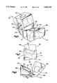
- FIG. 3is an enlarged pictorial illustration of a connector member of a first embodiment used in the left side retainer assembly of FIG. 1;
- FIG. 4is a lateral to medial view of the connector member of FIG. 3;
- FIG. 5is a caudad to cephalad view of the connector member of FIG. 3;
- FIG. 6is an enlarged pictorial illustration of a connector member of a second embodiment for a left side retainer assembly
- FIG. 7is a lateral to medial view of the connector member of FIG. 6.
- FIG. 8is a caudad to cephalad view of the connector member of FIG. 6.
- FIGS. 1 and 2A human spinal column 10 to which a pair of retainer assemblies 12 and 14 are connected is illustrated in FIGS. 1 and 2.
- the retainer assemblies 12 and 14retain portions of the spinal column, that is cervical vertebrae 16 and thoracic vertebrae 18, in a desired spatial relationship relative to each other.
- the retainer assemblies 12 and 14have the same construction and include fasteners 20 located in the cervical vertebrae 16 of the spinal column 10 and made of a bio-compatible material, such as stainless steel.
- the fasteners 20have threaded end portions which engage the vertebrae 16 to fixedly mount the fasteners in the vertebrae.
- Each of the retainer assemblies 12 and 14also includes a longitudinal member such as the depicted cylindrical rod 26 which extends along the spinal column.
- the rod 26is made of a bio-compatible material such as stainless steel.
- Each of the rods 26has a length which is at least sufficient to enable the rod to span at least two of the cervical vertebrae 16.
- the rod 26has a relatively large cross-sectional area located adjacent the thoracic vertebrae 18 of the spinal column 10 and a relatively small cross-sectional area located adjacent the cervical vertebrae 16 of the spinal column.
- the rods 26are bent to conform to a desired curvature of the spinal column 10 in all or any of three possible anatomic planes.
- the rods 26are connected to the base of the skull by connectors 27.
- the rods 26extend through openings in the connectors 27 and are fixed to the connectors 27 by set screws.
- the connectors 27have openings for receiving a fastener such as a screw 28 or a wire 29 for connecting the connectors 27 to the skull.
- Hooks 30,such as those disclosed in U.S. Pat. No. 5,024,213, interconnect the rods 26 to the thoracic vertebrae 18 of the spinal column 10 as is well known in the art.
- hooks 30are shown connecting the rods 26 to the thoracic vertebrae 18, any known apparatus can be used to connect the rods to the thoracic vertebrae.
- Transverse connectors 31,such as those disclosed in U.S. Pat. No. 5,084,049, interconnect the retainer assemblies 12 and 14, also as is well known in the art.
- Connector members 32 of a first embodimentinterconnect the rods 26 and the fasteners 20 in the cervical region of the spinal column 10.
- Each of the connector members 32is provided with a first opening 36 through which the rod 26 extends (FIG. 3).
- the first opening 36extends through the connector member in a first direction indicated by arrow 37.
- Each of the connector members 32has a mounting section 38 with a second tapered opening 40 through which the fastener 20 extends.
- the second opening 40extends through the connector member in a second direction indicated by arrow 42.
- the connector member 32includes top and bottom surfaces 46 and 48 (FIG. 4) when connected to the spinal column 10.
- the longitudinal axis of the first opening 36, through which the rod 26 extends,is perpendicular to the top and bottom surfaces 46 and 48.
- the mounting section 38has a side surface 50 that extends at an acute angle X, in FIG. 4, to the top and bottom surfaces 46 and 48. Therefore, the second direction 42, in which the second opening 40 extends, extends at an acute angle to a plane containing the top surface 46 and a plane containing the bottom surface 48.
- a surface 51 of the connector member 32 that engages the vertebra 16 when the connector member is connected to the vertebramay also extend at an angle to the top and bottom surfaces 46 and 48.
- the connector member 32also includes a surface 52 (FIGS. 3 and 5) that is parallel to the longitudinal axis of the first opening 36 through which the rod 26 extends.
- the side surface 50 of the mounting section 38extends at an acute angle Y, in FIG. 5, to the surface 52. Therefore, the second direction 42 also extends at an acute angle to a plane containing the surface 52.
- the connector member 32has a threaded opening 56 for receiving a set screw (not shown).
- the set screwengages the rod 26 to push the rod against the side of the first opening 36.
- the set screwclamps the rod 26 to the connector member 32.
- FIGS. 6-8The embodiment of the invention illustrated in FIGS. 6-8 is generally similar to the embodiment of the invention illustrated in FIGS. 3-5, similar numerals will be utilized to designate similar components, the suffix letter "a" being associated with the numerals of FIGS. 6-8 to avoid confusion.
- Connector member 32ais provided with a first opening 36a through which the rod 26 extends (FIG. 6).
- the first opening 36aextends through the connector member in a first direction indicated by arrow 37a.
- the connector member 32ahas a mounting section 38a with a second opening 40a through which the fastener 20 extends.
- the second opening 40aextends through the connector member in a second direction indicated by the arrow 42a.
- the opening 40aincludes a tapered portion 60 and a spherical counter sink 62 for receiving a head of a fastener 20.
- the tapered portion 60 of the opening 40aextends through a side surface 64 and a surface 51a that engages the vertebra when the connector member 32a is connected to the vertebra.
- the connector member 32aincludes top and bottom surfaces 46a and 48a (FIG. 7) when connected to the spinal column 10.
- the longitudinal axis of the first opening 36a through which the rod 26 extendsis perpendicular to the top and bottom surfaces 46a and 48a.
- the mounting section 38ahas a side surface 50a that extends at an acute angle X, in FIG. 7, to the top and bottom surfaces 46a and 48a. Therefore, the second direction 42a, in which the second opening 40a extends, extends at an acute angle to a plane containing the top surface 46a and a plane containing the bottom surface 48a.
- the surface 51aalso extends at an angle to the top and bottom surfaces 46a and 48a.
- the connector member 32aalso includes a surface 52a (FIGS. 6 and 8) that is parallel to the longitudinal axis of the first opening 36a through which the rod 26 extends.
- the side surface 50a of the mounting section 38aextends at an acute angle Y, in FIG. 8, to the surface 52a. Therefore, the second direction 42a also extends at an acute angle to a plane containing the surface 52a.
- the connector member 32ahas a threaded opening 56a for receiving a set screw (not shown).
- the set screwengages the rod 26 to push the rod against the side of the first opening 36a.
- the set screwclamps the rod 26 to the connector member 32a.
- connector members 32 and 32aare shown with threaded openings 56 and 56a for receiving a set screw, any known manner for clamping the rod 26 to the connector members may be used.
- connector members 32 and 32ahave been shown with connectors 27, hooks 30 and transverse connectors 31, it is contemplated that they could be used alone in maintaining only the cervical vertebrae 16 in a desired spatial relationship or with other connectors such as clamps and sublaminar wires.
- the configuration of the connector members 32 and 32aassure that the fasteners 20 extend into the cervical vertebrae 16 in a direction to provide a secure attachment of the rods 26 to the cervical vertebrae (FIG. 2).
- the angles that the side surfaces 50 and 50a of the mounting sections 38 and 38a make with the top surfaces 46 and 46a, the bottom surfaces 48 and 48a, and with the surfaces 52 and 52adepend on the configuration of the cervical vertebrae.
Landscapes
- Health & Medical Sciences (AREA)
- Orthopedic Medicine & Surgery (AREA)
- Life Sciences & Earth Sciences (AREA)
- Neurology (AREA)
- Surgery (AREA)
- Heart & Thoracic Surgery (AREA)
- Engineering & Computer Science (AREA)
- Biomedical Technology (AREA)
- Nuclear Medicine, Radiotherapy & Molecular Imaging (AREA)
- Medical Informatics (AREA)
- Molecular Biology (AREA)
- Animal Behavior & Ethology (AREA)
- General Health & Medical Sciences (AREA)
- Public Health (AREA)
- Veterinary Medicine (AREA)
- Surgical Instruments (AREA)
- Prostheses (AREA)
Abstract
Description
Claims (6)
Priority Applications (1)
| Application Number | Priority Date | Filing Date | Title |
|---|---|---|---|
| US08/014,312US5403314A (en) | 1993-02-05 | 1993-02-05 | Apparatus for retaining spinal elements in a desired spatial relationship |
Applications Claiming Priority (1)
| Application Number | Priority Date | Filing Date | Title |
|---|---|---|---|
| US08/014,312US5403314A (en) | 1993-02-05 | 1993-02-05 | Apparatus for retaining spinal elements in a desired spatial relationship |
Publications (1)
| Publication Number | Publication Date |
|---|---|
| US5403314Atrue US5403314A (en) | 1995-04-04 |
Family
ID=21764720
Family Applications (1)
| Application Number | Title | Priority Date | Filing Date |
|---|---|---|---|
| US08/014,312Expired - LifetimeUS5403314A (en) | 1993-02-05 | 1993-02-05 | Apparatus for retaining spinal elements in a desired spatial relationship |
Country Status (1)
| Country | Link |
|---|---|
| US (1) | US5403314A (en) |
Cited By (88)
| Publication number | Priority date | Publication date | Assignee | Title |
|---|---|---|---|---|
| US5545164A (en)* | 1992-12-28 | 1996-08-13 | Advanced Spine Fixation Systems, Incorporated | Occipital clamp assembly for cervical spine rod fixation |
| WO1996037159A1 (en)* | 1995-05-22 | 1996-11-28 | Synthes Ag Chur | Clamp jaw for a spinal fixation device |
| US5681312A (en)* | 1996-05-31 | 1997-10-28 | Acromed Corporation | Spine construct with band clamp |
| US5713900A (en)* | 1996-05-31 | 1998-02-03 | Acromed Corporation | Apparatus for retaining bone portions in a desired spatial relationship |
| US5800433A (en)* | 1996-05-31 | 1998-09-01 | Acromed Corporation | Spinal column retaining apparatus |
| US5843082A (en)* | 1996-05-31 | 1998-12-01 | Acromed Corporation | Cervical spine stabilization method and system |
| FR2769490A1 (en)* | 1997-10-13 | 1999-04-16 | Dimso Sa | Fixing for anchoring rod to thin bone wall |
| US5928233A (en)* | 1995-12-22 | 1999-07-27 | Ohio Medical Instrument Co., Inc. | Spinal fixation device with laterally attachable connectors |
| US5961518A (en)* | 1997-05-15 | 1999-10-05 | Spinal Concepts, Inc. | Polyaxial pedicle screw having a through bar clamp locking mechanism |
| US5997539A (en)* | 1997-05-15 | 1999-12-07 | Spinal Concepts, Inc. | Polyaxial pedicle screw having a compression locking rod gripping mechanism |
| US6030388A (en)* | 1995-03-16 | 2000-02-29 | Alphatech Manufacturing, Inc. | Top tightening bone fixation apparatus |
| US6066140A (en)* | 1995-01-25 | 2000-05-23 | Sdgi Holdings, Inc. | Spinal rod transverse connectors |
| US6086588A (en)* | 1997-05-07 | 2000-07-11 | Aesculap Ag & Co. Kg | Osteosynthesis system for vertebra arthrodesis |
| US6099528A (en)* | 1997-05-29 | 2000-08-08 | Sofamor S.N.C. | Vertebral rod for spinal osteosynthesis instrumentation and osteosynthesis instrumentation, including said rod |
| US6179838B1 (en) | 1998-02-24 | 2001-01-30 | Daniel Fiz | Bone fixation arrangements and method |
| US6193720B1 (en) | 1998-11-30 | 2001-02-27 | Depuy Orthopaedics, Inc. | Cervical spine stabilization method and system |
| US6328739B1 (en)* | 1999-05-04 | 2001-12-11 | Industrial Technology Research Institute | Enhanced spine fixation apparatus |
| WO2002009604A1 (en)* | 2000-08-02 | 2002-02-07 | Depuy International Limited | Surgical fixings |
| WO2001091656A3 (en)* | 2000-06-01 | 2002-05-30 | Hipokrat Tibbi Malzemeler Imal | Spinal system |
| US20020107573A1 (en)* | 1999-03-07 | 2002-08-08 | Discure Ltd. | Method and apparatus for computerized surgery |
| US20020128715A1 (en)* | 2000-08-08 | 2002-09-12 | Vincent Bryan | Implantable joint prosthesis |
| US20030055426A1 (en)* | 2001-09-14 | 2003-03-20 | John Carbone | Biased angulation bone fixation assembly |
| US6562045B2 (en) | 2001-02-13 | 2003-05-13 | Sdgi Holdings, Inc. | Machining apparatus |
| US20030135277A1 (en)* | 2001-11-26 | 2003-07-17 | Sdgi Holdings, Inc. | Implantable joint prosthesis and associated instrumentation |
| US20030153913A1 (en)* | 2002-02-13 | 2003-08-14 | Moti Altarac | Occipital plate and rod system |
| US20030199738A1 (en)* | 2000-08-08 | 2003-10-23 | Sdgi Holdings,Inc. | Clamping apparatus and methods |
| US20030199982A1 (en)* | 1998-09-04 | 2003-10-23 | Sdgi Holdings, Inc. | Peanut spectacle multi discoid thoraco-lumbar disc prosthesis |
| US6679883B2 (en) | 2001-10-31 | 2004-01-20 | Ortho Development Corporation | Cervical plate for stabilizing the human spine |
| US20040054411A1 (en)* | 2000-08-08 | 2004-03-18 | Sdgi Holdings, Inc. | Wear-resistant endoprosthetic devices |
| US20040098131A1 (en)* | 1996-07-22 | 2004-05-20 | Sdgi Holdings, Inc. | Human spinal disc prosthesis |
| US6749635B1 (en) | 1998-09-04 | 2004-06-15 | Sdgi Holdings, Inc. | Peanut spectacle multi discoid thoraco-lumbar disc prosthesis |
| US6755830B2 (en) | 2001-07-04 | 2004-06-29 | Sofamor S.N.C. | Connector for a spinal fixation member |
| US20040153077A1 (en)* | 2000-11-10 | 2004-08-05 | Lutz Biedermann | Bone screw |
| US20040158254A1 (en)* | 2003-02-12 | 2004-08-12 | Sdgi Holdings, Inc. | Instrument and method for milling a path into bone |
| US20040210216A1 (en)* | 2003-04-17 | 2004-10-21 | Farris Robert A | Spinal fixation system and method |
| WO2005032325A2 (en) | 2003-10-06 | 2005-04-14 | Mazor Surgical Technologies Ltd. | Apparatus for spinal fixation of vertebrae |
| EP1322241A4 (en)* | 2000-09-20 | 2005-05-11 | Kevin Jon Lawson | Cable-anchor system for spinal fixation |
| US20050154391A1 (en)* | 2003-12-30 | 2005-07-14 | Thomas Doherty | Bone anchor assemblies |
| US20050154393A1 (en)* | 2003-12-30 | 2005-07-14 | Thomas Doherty | Bone anchor assemblies and methods of manufacturing bone anchor assemblies |
| US6949105B2 (en) | 2000-08-08 | 2005-09-27 | Sdgi Holdings, Inc. | Method and apparatus for stereotactic implantation |
| US20050277919A1 (en)* | 2004-05-28 | 2005-12-15 | Depuy Spine, Inc. | Anchoring systems and methods for correcting spinal deformities |
| US20050277926A1 (en)* | 2004-06-15 | 2005-12-15 | Farris Robert A | Spinal rod system |
| US20060195098A1 (en)* | 2005-02-22 | 2006-08-31 | Jorg Schumacher | Implant system and fastening element for an implant system |
| US20060200128A1 (en)* | 2003-04-04 | 2006-09-07 | Richard Mueller | Bone anchor |
| US20060229611A1 (en)* | 2005-03-30 | 2006-10-12 | Sdgi Holdings, Inc. | Spinal rod connector |
| US20060247627A1 (en)* | 2005-04-29 | 2006-11-02 | Sdgi Holdings, Inc. | Spinal construct system |
| US7147665B1 (en) | 1998-07-22 | 2006-12-12 | Sdgi Holdings, Inc. | Threaded cylindrical multidiscoid single or multiple array disc prosthesis |
| US20070005063A1 (en)* | 2005-06-20 | 2007-01-04 | Sdgi Holdings, Inc. | Multi-level multi-functional spinal stabilization systems and methods |
| US20070233070A1 (en)* | 2006-03-01 | 2007-10-04 | Sdgi Holdings, Inc. | Low profile spinal rod connector system |
| US20070270838A1 (en)* | 2006-05-08 | 2007-11-22 | Sdgi Holdings, Inc. | Dynamic spinal stabilization device with dampener |
| US20070270836A1 (en)* | 2006-05-08 | 2007-11-22 | Sdgi Holdings, Inc. | Dynamic spinal stabilization members and methods |
| US20070270805A1 (en)* | 2006-04-07 | 2007-11-22 | Sdgi Holdings, Inc. | Spinal rod connector system and method for a bone anchor |
| US20070270837A1 (en)* | 2006-05-08 | 2007-11-22 | Sdgi Holdings, Inc. | Load bearing flexible spinal connecting element |
| US20080045951A1 (en)* | 2006-08-16 | 2008-02-21 | Depuy Spine, Inc. | Modular multi-level spine stabilization system and method |
| US20080195100A1 (en)* | 2007-02-08 | 2008-08-14 | Warsaw Orthopedic, Inc. | Adjustable coupling systems for spinal stabilization members |
| US20080281362A1 (en)* | 2007-05-09 | 2008-11-13 | Jeremy Lemoine | Device and system for cranial support |
| US20090163955A1 (en)* | 2007-12-19 | 2009-06-25 | Missoum Moumene | Polymeric Pedicle Rods and Methods of Manufacturing |
| US20090326584A1 (en)* | 2008-06-27 | 2009-12-31 | Michael Andrew Slivka | Spinal Dynamic Stabilization Rods Having Interior Bumpers |
| US20090326583A1 (en)* | 2008-06-25 | 2009-12-31 | Missoum Moumene | Posterior Dynamic Stabilization System With Flexible Ligament |
| US7736380B2 (en) | 2004-12-21 | 2010-06-15 | Rhausler, Inc. | Cervical plate system |
| US7766947B2 (en) | 2001-10-31 | 2010-08-03 | Ortho Development Corporation | Cervical plate for stabilizing the human spine |
| US20100211104A1 (en)* | 2009-02-13 | 2010-08-19 | Missoum Moumene | Dual Spring Posterior Dynamic Stabilization Device With Elongation Limiting Elastomers |
| US20100234893A1 (en)* | 2009-03-10 | 2010-09-16 | Andrew Iott | Spinal Implant Connection Assembly |
| US20100249845A1 (en)* | 2007-10-23 | 2010-09-30 | Alain Meunier | Fixing devices and stabilization systems using said fixing devices |
| US7854752B2 (en) | 2004-08-09 | 2010-12-21 | Theken Spine, Llc | System and method for dynamic skeletal stabilization |
| US20100331886A1 (en)* | 2009-06-25 | 2010-12-30 | Jonathan Fanger | Posterior Dynamic Stabilization Device Having A Mobile Anchor |
| US8025681B2 (en) | 2006-03-29 | 2011-09-27 | Theken Spine, Llc | Dynamic motion spinal stabilization system |
| US20110238119A1 (en)* | 2010-03-24 | 2011-09-29 | Missoum Moumene | Composite Material Posterior Dynamic Stabilization Spring Rod |
| US8197517B1 (en) | 2007-05-08 | 2012-06-12 | Theken Spine, Llc | Frictional polyaxial screw assembly |
| US20120158065A1 (en)* | 2009-06-22 | 2012-06-21 | Jean-Luc Jouve | Vertebral osteosynthesis equipment |
| WO2012176096A1 (en)* | 2011-06-22 | 2012-12-27 | Medicrea International | Vertebral osteosynthesis equipment |
| US20130085534A1 (en)* | 2011-09-30 | 2013-04-04 | Nicolas Hainard | Connectors for a secondary bone anchor |
| US9060813B1 (en) | 2008-02-29 | 2015-06-23 | Nuvasive, Inc. | Surgical fixation system and related methods |
| US9084634B1 (en) | 2010-07-09 | 2015-07-21 | Theken Spine, Llc | Uniplanar screw |
| US9198696B1 (en) | 2010-05-27 | 2015-12-01 | Nuvasive, Inc. | Cross-connector and related methods |
| US9247964B1 (en) | 2011-03-01 | 2016-02-02 | Nuasive, Inc. | Spinal Cross-connector |
| US9387013B1 (en) | 2011-03-01 | 2016-07-12 | Nuvasive, Inc. | Posterior cervical fixation system |
| US10307186B2 (en) | 2016-12-02 | 2019-06-04 | Nuvasive, Inc. | Surgical band clamp system |
| US10499954B2 (en) | 2016-03-10 | 2019-12-10 | Nuvasive, Inc. | Bone anchor with deployable purchase element |
| US10507043B1 (en) | 2017-10-11 | 2019-12-17 | Seaspine Orthopedics Corporation | Collet for a polyaxial screw assembly |
| US10595904B2 (en) | 2011-09-14 | 2020-03-24 | Band-Lok, Llc | Tensioning instrument and band clamp tensioning system |
| US10603083B1 (en) | 2010-07-09 | 2020-03-31 | Theken Spine, Llc | Apparatus and method for limiting a range of angular positions of a screw |
| US20200237411A1 (en)* | 2019-01-30 | 2020-07-30 | Medos International Sarl | Surgical device for spinal fixation |
| WO2020219735A1 (en) | 2019-04-26 | 2020-10-29 | Warsaw Orthopedic, Inc. | Spinal implant system and method |
| US20210121203A1 (en)* | 2019-10-29 | 2021-04-29 | Globus Medical, Inc. | Sublaminar band clamp |
| US11026722B2 (en) | 2011-09-14 | 2021-06-08 | Orthopediatrics Corp. | Orthopedic tethered implants and system |
| US20210290272A1 (en)* | 2015-12-23 | 2021-09-23 | Xiangyang Ma | Customized posterior atlantoaxial reduction fixatorwith screws and rods |
| US11331125B1 (en) | 2021-10-07 | 2022-05-17 | Ortho Inventions, Llc | Low profile rod-to-rod coupler |
Citations (5)
| Publication number | Priority date | Publication date | Assignee | Title |
|---|---|---|---|---|
| US4111580A (en)* | 1976-12-30 | 1978-09-05 | The Boeing Company | Continuously curved fastener head and countersink have interference fit |
| US4648388A (en)* | 1985-11-01 | 1987-03-10 | Acromed Corporation | Apparatus and method for maintaining vertebrae in a desired relationship |
| US4655199A (en)* | 1985-03-29 | 1987-04-07 | Acromed Corporation | Spinal column straightening apparatus |
| US5053034A (en)* | 1990-08-03 | 1991-10-01 | Sven Olerud | Spinal joint |
| US5254118A (en)* | 1991-12-04 | 1993-10-19 | Srdjian Mirkovic | Three dimensional spine fixation system |
- 1993
- 1993-02-05USUS08/014,312patent/US5403314A/ennot_activeExpired - Lifetime
Patent Citations (6)
| Publication number | Priority date | Publication date | Assignee | Title |
|---|---|---|---|---|
| US4111580A (en)* | 1976-12-30 | 1978-09-05 | The Boeing Company | Continuously curved fastener head and countersink have interference fit |
| US4655199A (en)* | 1985-03-29 | 1987-04-07 | Acromed Corporation | Spinal column straightening apparatus |
| US4648388A (en)* | 1985-11-01 | 1987-03-10 | Acromed Corporation | Apparatus and method for maintaining vertebrae in a desired relationship |
| US4648388B1 (en)* | 1985-11-01 | 1995-10-31 | Acromed Corp | Apparatus and method for maintaining vertebrae in a desired relationship |
| US5053034A (en)* | 1990-08-03 | 1991-10-01 | Sven Olerud | Spinal joint |
| US5254118A (en)* | 1991-12-04 | 1993-10-19 | Srdjian Mirkovic | Three dimensional spine fixation system |
Cited By (195)
| Publication number | Priority date | Publication date | Assignee | Title |
|---|---|---|---|---|
| US5545164A (en)* | 1992-12-28 | 1996-08-13 | Advanced Spine Fixation Systems, Incorporated | Occipital clamp assembly for cervical spine rod fixation |
| USRE42576E1 (en) | 1994-11-14 | 2011-07-26 | Warsaw Orthopedic, Inc. | Human spinal disc prosthesis |
| USRE42480E1 (en) | 1994-11-14 | 2011-06-21 | Warsaw Orthopedic, Inc. | Human spinal disc prothesis with hinges |
| US6602254B2 (en) | 1995-01-25 | 2003-08-05 | Sdgi Holdings, Inc. | Spinal rod transverse connectors |
| US6471704B2 (en) | 1995-01-25 | 2002-10-29 | Sdgi Holdings, Inc. | Spinal rod transverse connectors |
| US6254603B1 (en) | 1995-01-25 | 2001-07-03 | Sdgi Holdings, Inc. | Spinal rod transverse connectors |
| US6066140A (en)* | 1995-01-25 | 2000-05-23 | Sdgi Holdings, Inc. | Spinal rod transverse connectors |
| US6030388A (en)* | 1995-03-16 | 2000-02-29 | Alphatech Manufacturing, Inc. | Top tightening bone fixation apparatus |
| WO1996037159A1 (en)* | 1995-05-22 | 1996-11-28 | Synthes Ag Chur | Clamp jaw for a spinal fixation device |
| US5735852A (en)* | 1995-05-22 | 1998-04-07 | Synthes (U.S.A.) | Clamp jaw for a spinal affixation device |
| US7491219B2 (en) | 1995-09-04 | 2009-02-17 | Active Implants Corporation | Method and apparatus for computerized surgery |
| US20070093689A1 (en)* | 1995-09-04 | 2007-04-26 | Active Implants Corporation | Method and apparatus for computerized surgery |
| US7497868B2 (en) | 1995-09-04 | 2009-03-03 | Active Implants Corporation | Method and apparatus for computerized surgery |
| US20080071374A1 (en)* | 1995-09-04 | 2008-03-20 | Active Implants Corporation | Method and apparatus for computerized surgery |
| US20050177239A1 (en)* | 1995-09-04 | 2005-08-11 | Amiram Steinberg | Method and apparatus for computerized surgery |
| US20050197701A1 (en)* | 1995-09-04 | 2005-09-08 | Amiram Steinberg | Method and apparatus for computerized surgery |
| US5928233A (en)* | 1995-12-22 | 1999-07-27 | Ohio Medical Instrument Co., Inc. | Spinal fixation device with laterally attachable connectors |
| US5800433A (en)* | 1996-05-31 | 1998-09-01 | Acromed Corporation | Spinal column retaining apparatus |
| US5713900A (en)* | 1996-05-31 | 1998-02-03 | Acromed Corporation | Apparatus for retaining bone portions in a desired spatial relationship |
| US6036693A (en)* | 1996-05-31 | 2000-03-14 | Depuy Orthopaedics, Inc. | Cervical spine stabilization method and system |
| US6214005B1 (en) | 1996-05-31 | 2001-04-10 | Depuy Acromed, Inc. | Spinal column retaining apparatus |
| US5843082A (en)* | 1996-05-31 | 1998-12-01 | Acromed Corporation | Cervical spine stabilization method and system |
| US5681312A (en)* | 1996-05-31 | 1997-10-28 | Acromed Corporation | Spine construct with band clamp |
| US20040098131A1 (en)* | 1996-07-22 | 2004-05-20 | Sdgi Holdings, Inc. | Human spinal disc prosthesis |
| US6086588A (en)* | 1997-05-07 | 2000-07-11 | Aesculap Ag & Co. Kg | Osteosynthesis system for vertebra arthrodesis |
| US5997539A (en)* | 1997-05-15 | 1999-12-07 | Spinal Concepts, Inc. | Polyaxial pedicle screw having a compression locking rod gripping mechanism |
| US6017344A (en)* | 1997-05-15 | 2000-01-25 | Spinal Concepts, Inc. | Polyaxial pedicle screw having a through bar clamp locking mechanism |
| US5961518A (en)* | 1997-05-15 | 1999-10-05 | Spinal Concepts, Inc. | Polyaxial pedicle screw having a through bar clamp locking mechanism |
| US6102912A (en)* | 1997-05-29 | 2000-08-15 | Sofamor S.N.C. | Vertebral rod of constant section for spinal osteosynthesis instrumentations |
| US6099528A (en)* | 1997-05-29 | 2000-08-08 | Sofamor S.N.C. | Vertebral rod for spinal osteosynthesis instrumentation and osteosynthesis instrumentation, including said rod |
| WO1999018877A1 (en)* | 1997-10-13 | 1999-04-22 | Dimso (Distribution Medicale Du Sud-Ouest) | Device for fixing a rod in a thin bone wall |
| US6375656B1 (en) | 1997-10-13 | 2002-04-23 | Dimso (Distribution Medicale Du Sud-Ouest) | Device for fixing a rod to a thin bone wall |
| FR2769490A1 (en)* | 1997-10-13 | 1999-04-16 | Dimso Sa | Fixing for anchoring rod to thin bone wall |
| US6179838B1 (en) | 1998-02-24 | 2001-01-30 | Daniel Fiz | Bone fixation arrangements and method |
| US7147665B1 (en) | 1998-07-22 | 2006-12-12 | Sdgi Holdings, Inc. | Threaded cylindrical multidiscoid single or multiple array disc prosthesis |
| US20060074489A1 (en)* | 1998-09-04 | 2006-04-06 | Sdgi Holdings, Inc. | Peanut spectacle multi discoid thoraco-lumbar disc prosthesis |
| US6749635B1 (en) | 1998-09-04 | 2004-06-15 | Sdgi Holdings, Inc. | Peanut spectacle multi discoid thoraco-lumbar disc prosthesis |
| US20030199982A1 (en)* | 1998-09-04 | 2003-10-23 | Sdgi Holdings, Inc. | Peanut spectacle multi discoid thoraco-lumbar disc prosthesis |
| US6193720B1 (en) | 1998-11-30 | 2001-02-27 | Depuy Orthopaedics, Inc. | Cervical spine stabilization method and system |
| US7338526B2 (en) | 1999-03-07 | 2008-03-04 | Active Implants Corporation | Method and apparatus for computerized surgery |
| US9668875B2 (en) | 1999-03-07 | 2017-06-06 | Nuvasive, Inc. | Method and apparatus for computerized surgery |
| US9827109B2 (en) | 1999-03-07 | 2017-11-28 | Nuvasive, Inc. | Methods and apparatus for performing spine surgery |
| US20020107573A1 (en)* | 1999-03-07 | 2002-08-08 | Discure Ltd. | Method and apparatus for computerized surgery |
| US9017313B2 (en) | 1999-03-07 | 2015-04-28 | Nuvasive, Inc. | Method and apparatus for computerized surgery |
| US6328739B1 (en)* | 1999-05-04 | 2001-12-11 | Industrial Technology Research Institute | Enhanced spine fixation apparatus |
| WO2001091656A3 (en)* | 2000-06-01 | 2002-05-30 | Hipokrat Tibbi Malzemeler Imal | Spinal system |
| WO2002009604A1 (en)* | 2000-08-02 | 2002-02-07 | Depuy International Limited | Surgical fixings |
| US8092542B2 (en) | 2000-08-08 | 2012-01-10 | Warsaw Orthopedic, Inc. | Implantable joint prosthesis |
| US7641692B2 (en) | 2000-08-08 | 2010-01-05 | Warsaw Orthopedic, Inc. | Implantable joint prosthesis |
| US20030199738A1 (en)* | 2000-08-08 | 2003-10-23 | Sdgi Holdings,Inc. | Clamping apparatus and methods |
| US20100070042A1 (en)* | 2000-08-08 | 2010-03-18 | Warsaw Orthopedic, Inc. | Implantable Joint Prosthesis |
| US7601174B2 (en) | 2000-08-08 | 2009-10-13 | Warsaw Orthopedic, Inc. | Wear-resistant endoprosthetic devices |
| US20020128715A1 (en)* | 2000-08-08 | 2002-09-12 | Vincent Bryan | Implantable joint prosthesis |
| US20040054411A1 (en)* | 2000-08-08 | 2004-03-18 | Sdgi Holdings, Inc. | Wear-resistant endoprosthetic devices |
| US6949105B2 (en) | 2000-08-08 | 2005-09-27 | Sdgi Holdings, Inc. | Method and apparatus for stereotactic implantation |
| EP1322241A4 (en)* | 2000-09-20 | 2005-05-11 | Kevin Jon Lawson | Cable-anchor system for spinal fixation |
| US20110125195A1 (en)* | 2000-10-11 | 2011-05-26 | Lutz Biedermann | Bone Screw |
| US9498256B2 (en) | 2000-11-10 | 2016-11-22 | Biedermann Technologies Gmbh & Co. Kg | Bone screw |
| US20060106383A1 (en)* | 2000-11-10 | 2006-05-18 | Biedermann Motech Gmbh | Bone screw |
| US7785354B2 (en) | 2000-11-10 | 2010-08-31 | Biedermann Motech Gmbh | Bone screw |
| US10058353B2 (en) | 2000-11-10 | 2018-08-28 | Biedermann Technologies Gmbh & Co. Kg | Bone screw |
| US20110066189A2 (en)* | 2000-11-10 | 2011-03-17 | Biedermann Motech Gmbh | Bone screw |
| US9566093B2 (en) | 2000-11-10 | 2017-02-14 | Biedermann Technologies Gmbh & Co. Kg | Bone screw |
| US20060084995A1 (en)* | 2000-11-10 | 2006-04-20 | Biedermann Motech Gmbh | Bone screw |
| US8945194B2 (en) | 2000-11-10 | 2015-02-03 | Biedermann Technologies Gmbh & Co. Kg | Bone screw |
| US8864803B2 (en) | 2000-11-10 | 2014-10-21 | Biedermann Technologies Gmbh & Co. Kg | Bone screw |
| US20040153077A1 (en)* | 2000-11-10 | 2004-08-05 | Lutz Biedermann | Bone screw |
| US8409260B2 (en) | 2000-11-10 | 2013-04-02 | Biedermann Technologies Gmbh & Co. Kg | Bone screw |
| US11197694B2 (en) | 2000-11-10 | 2021-12-14 | Biedermann Technologies Gmbh & Co. Kg | Bone screw |
| US6562045B2 (en) | 2001-02-13 | 2003-05-13 | Sdgi Holdings, Inc. | Machining apparatus |
| US6755830B2 (en) | 2001-07-04 | 2004-06-29 | Sofamor S.N.C. | Connector for a spinal fixation member |
| US9662144B2 (en) | 2001-09-14 | 2017-05-30 | Stryker European Holdings I, Llc | Stabilizing bone using spinal fixation devices and systems |
| US8506600B2 (en) | 2001-09-14 | 2013-08-13 | Stryker Spine | Methods for stabilizing bone using spinal fixation devices |
| US10517646B2 (en) | 2001-09-14 | 2019-12-31 | Stryker European Holdings I, Llc | Stabilizing bone using spinal fixation devices and systems |
| US6974460B2 (en) | 2001-09-14 | 2005-12-13 | Stryker Spine | Biased angulation bone fixation assembly |
| US20030055426A1 (en)* | 2001-09-14 | 2003-03-20 | John Carbone | Biased angulation bone fixation assembly |
| EP1293168A3 (en)* | 2001-09-14 | 2003-08-20 | Stryker Spine | Biased angulation bone fixation assembly |
| AU2002301000B2 (en)* | 2001-09-14 | 2008-08-14 | Stryker European Operations Holdings Llc | Biased angulation bone fixation assembly |
| US8870930B2 (en) | 2001-09-14 | 2014-10-28 | Stryker Spine | Methods for stabilizing bone using spinal fixation devices |
| US20040243126A1 (en)* | 2001-09-14 | 2004-12-02 | Stryker Spine | Methods for stabilizing bone using spinal fixation devices |
| US6679883B2 (en) | 2001-10-31 | 2004-01-20 | Ortho Development Corporation | Cervical plate for stabilizing the human spine |
| US7766947B2 (en) | 2001-10-31 | 2010-08-03 | Ortho Development Corporation | Cervical plate for stabilizing the human spine |
| US20030135277A1 (en)* | 2001-11-26 | 2003-07-17 | Sdgi Holdings, Inc. | Implantable joint prosthesis and associated instrumentation |
| US7025787B2 (en) | 2001-11-26 | 2006-04-11 | Sdgi Holdings, Inc. | Implantable joint prosthesis and associated instrumentation |
| US20050096746A1 (en)* | 2001-11-26 | 2005-05-05 | Sdgi Holdings, Inc. | Instrumentation and associated methods for joint prosthesis implantation |
| US7232441B2 (en) | 2002-02-13 | 2007-06-19 | Cross Medicalproducts, Inc. | Occipital plate and rod system |
| US20030153913A1 (en)* | 2002-02-13 | 2003-08-14 | Moti Altarac | Occipital plate and rod system |
| US20040158254A1 (en)* | 2003-02-12 | 2004-08-12 | Sdgi Holdings, Inc. | Instrument and method for milling a path into bone |
| US20060200128A1 (en)* | 2003-04-04 | 2006-09-07 | Richard Mueller | Bone anchor |
| US20040210216A1 (en)* | 2003-04-17 | 2004-10-21 | Farris Robert A | Spinal fixation system and method |
| EP1682018A4 (en)* | 2003-10-06 | 2008-12-10 | Mazor Surgical Tech Ltd | Apparatus for spinal fixation of vertebrae |
| WO2005032325A2 (en) | 2003-10-06 | 2005-04-14 | Mazor Surgical Technologies Ltd. | Apparatus for spinal fixation of vertebrae |
| JP2007507279A (en)* | 2003-10-06 | 2007-03-29 | メイザー サージカル テクノロジーズ リミテッド | Spinal fixation device |
| US20080071272A1 (en)* | 2003-10-06 | 2008-03-20 | Mazor Surgical Technologies, Ltd. | Apparatus for Spinal Fixation of Vertebrae |
| US7887567B2 (en) | 2003-10-06 | 2011-02-15 | Mazer Surgical Technologies, Ltd. | Apparatus for spinal fixation of vertebrae |
| US20050154393A1 (en)* | 2003-12-30 | 2005-07-14 | Thomas Doherty | Bone anchor assemblies and methods of manufacturing bone anchor assemblies |
| US20050203515A1 (en)* | 2003-12-30 | 2005-09-15 | Thomas Doherty | Bone anchor assemblies |
| US20050159750A1 (en)* | 2003-12-30 | 2005-07-21 | Thomas Doherty | Bone anchor assemblies and methods of manufacturing bone anchor assemblies |
| US20050154391A1 (en)* | 2003-12-30 | 2005-07-14 | Thomas Doherty | Bone anchor assemblies |
| US8992578B2 (en) | 2004-05-28 | 2015-03-31 | Depuy Synthes Products Llc | Anchoring systems and methods for correcting spinal deformities |
| US8540754B2 (en) | 2004-05-28 | 2013-09-24 | DePuy Synthes Products, LLC | Anchoring systems and methods for correcting spinal deformities |
| US20050277919A1 (en)* | 2004-05-28 | 2005-12-15 | Depuy Spine, Inc. | Anchoring systems and methods for correcting spinal deformities |
| US20110077688A1 (en)* | 2004-05-28 | 2011-03-31 | Depuy Spine, Inc. | Anchoring systems and methods for correcting spinal deformities |
| US7901435B2 (en) | 2004-05-28 | 2011-03-08 | Depuy Spine, Inc. | Anchoring systems and methods for correcting spinal deformities |
| US20050277926A1 (en)* | 2004-06-15 | 2005-12-15 | Farris Robert A | Spinal rod system |
| US7744634B2 (en) | 2004-06-15 | 2010-06-29 | Warsaw Orthopedic, Inc. | Spinal rod system |
| US7175622B2 (en) | 2004-06-15 | 2007-02-13 | Warsaw Orthopedic, Inc. | Spinal rod system |
| US20050277932A1 (en)* | 2004-06-15 | 2005-12-15 | Sdgi Holdings, Inc. | Spinal rod system |
| US7854752B2 (en) | 2004-08-09 | 2010-12-21 | Theken Spine, Llc | System and method for dynamic skeletal stabilization |
| US7736380B2 (en) | 2004-12-21 | 2010-06-15 | Rhausler, Inc. | Cervical plate system |
| US20060195098A1 (en)* | 2005-02-22 | 2006-08-31 | Jorg Schumacher | Implant system and fastening element for an implant system |
| US20060229611A1 (en)* | 2005-03-30 | 2006-10-12 | Sdgi Holdings, Inc. | Spinal rod connector |
| US7993371B2 (en) | 2005-04-29 | 2011-08-09 | Warsaw Orthopedic, Inc. | Spinal construct system |
| US20060247627A1 (en)* | 2005-04-29 | 2006-11-02 | Sdgi Holdings, Inc. | Spinal construct system |
| US7828825B2 (en) | 2005-06-20 | 2010-11-09 | Warsaw Orthopedic, Inc. | Multi-level multi-functional spinal stabilization systems and methods |
| US20070005063A1 (en)* | 2005-06-20 | 2007-01-04 | Sdgi Holdings, Inc. | Multi-level multi-functional spinal stabilization systems and methods |
| US20070233070A1 (en)* | 2006-03-01 | 2007-10-04 | Sdgi Holdings, Inc. | Low profile spinal rod connector system |
| US7699874B2 (en) | 2006-03-01 | 2010-04-20 | Warsaw Orthopedic, Inc. | Low profile spinal rod connector system |
| US8025681B2 (en) | 2006-03-29 | 2011-09-27 | Theken Spine, Llc | Dynamic motion spinal stabilization system |
| US20070270805A1 (en)* | 2006-04-07 | 2007-11-22 | Sdgi Holdings, Inc. | Spinal rod connector system and method for a bone anchor |
| US7867255B2 (en)* | 2006-04-07 | 2011-01-11 | Warsaw Orthopedic, Inc. | Spinal rod connector system and method for a bone anchor |
| US8012179B2 (en) | 2006-05-08 | 2011-09-06 | Warsaw Orthopedic, Inc. | Dynamic spinal stabilization members and methods |
| US20070270836A1 (en)* | 2006-05-08 | 2007-11-22 | Sdgi Holdings, Inc. | Dynamic spinal stabilization members and methods |
| US20070270837A1 (en)* | 2006-05-08 | 2007-11-22 | Sdgi Holdings, Inc. | Load bearing flexible spinal connecting element |
| US20070270838A1 (en)* | 2006-05-08 | 2007-11-22 | Sdgi Holdings, Inc. | Dynamic spinal stabilization device with dampener |
| US20100298883A1 (en)* | 2006-05-08 | 2010-11-25 | Warsaw Orthopedic, Inc. | Load Bearing Flexible Spinal Connecting Element |
| US8231657B2 (en) | 2006-05-08 | 2012-07-31 | Warsaw Orthopedic | Load bearing flexible spinal connecting element |
| US7785350B2 (en) | 2006-05-08 | 2010-08-31 | Warsaw Orthopedic, Inc. | Load bearing flexible spinal connecting element |
| US8814909B2 (en) | 2006-08-16 | 2014-08-26 | DePuy Synthes Products, LLC | Modular multi-level spine stabilization system and method |
| US8486112B2 (en) | 2006-08-16 | 2013-07-16 | DePuy Synthes Products, LLC | Modular multi-level spine stabilization system and method |
| US20080045951A1 (en)* | 2006-08-16 | 2008-02-21 | Depuy Spine, Inc. | Modular multi-level spine stabilization system and method |
| US7806913B2 (en) | 2006-08-16 | 2010-10-05 | Depuy Spine, Inc. | Modular multi-level spine stabilization system and method |
| US20110022095A1 (en)* | 2006-08-16 | 2011-01-27 | Depuy Spine, Inc. | Modular Multi-Level Spine Stabilization System and Method |
| US8372121B2 (en) | 2007-02-08 | 2013-02-12 | Warsaw Orthopedic, Inc. | Adjustable coupling systems for spinal stabilization members |
| US20080195100A1 (en)* | 2007-02-08 | 2008-08-14 | Warsaw Orthopedic, Inc. | Adjustable coupling systems for spinal stabilization members |
| US8197517B1 (en) | 2007-05-08 | 2012-06-12 | Theken Spine, Llc | Frictional polyaxial screw assembly |
| US20080281362A1 (en)* | 2007-05-09 | 2008-11-13 | Jeremy Lemoine | Device and system for cranial support |
| US8870869B2 (en)* | 2007-10-23 | 2014-10-28 | Zimmer Spine | Fixing devices and stabilization systems using said fixing devices |
| US20100249845A1 (en)* | 2007-10-23 | 2010-09-30 | Alain Meunier | Fixing devices and stabilization systems using said fixing devices |
| US20090163955A1 (en)* | 2007-12-19 | 2009-06-25 | Missoum Moumene | Polymeric Pedicle Rods and Methods of Manufacturing |
| US9232968B2 (en) | 2007-12-19 | 2016-01-12 | DePuy Synthes Products, Inc. | Polymeric pedicle rods and methods of manufacturing |
| US9060813B1 (en) | 2008-02-29 | 2015-06-23 | Nuvasive, Inc. | Surgical fixation system and related methods |
| US20090326583A1 (en)* | 2008-06-25 | 2009-12-31 | Missoum Moumene | Posterior Dynamic Stabilization System With Flexible Ligament |
| US20090326584A1 (en)* | 2008-06-27 | 2009-12-31 | Michael Andrew Slivka | Spinal Dynamic Stabilization Rods Having Interior Bumpers |
| US20100211104A1 (en)* | 2009-02-13 | 2010-08-19 | Missoum Moumene | Dual Spring Posterior Dynamic Stabilization Device With Elongation Limiting Elastomers |
| US8641734B2 (en) | 2009-02-13 | 2014-02-04 | DePuy Synthes Products, LLC | Dual spring posterior dynamic stabilization device with elongation limiting elastomers |
| US8628559B2 (en) | 2009-03-10 | 2014-01-14 | Globus Medical, Inc. | Spinal implant connection assembly |
| US8252030B2 (en) | 2009-03-10 | 2012-08-28 | Globus Medical, Inc. | Spinal implant connection assembly |
| US20100234893A1 (en)* | 2009-03-10 | 2010-09-16 | Andrew Iott | Spinal Implant Connection Assembly |
| US20120158065A1 (en)* | 2009-06-22 | 2012-06-21 | Jean-Luc Jouve | Vertebral osteosynthesis equipment |
| US20100331886A1 (en)* | 2009-06-25 | 2010-12-30 | Jonathan Fanger | Posterior Dynamic Stabilization Device Having A Mobile Anchor |
| US9320543B2 (en) | 2009-06-25 | 2016-04-26 | DePuy Synthes Products, Inc. | Posterior dynamic stabilization device having a mobile anchor |
| US20110238119A1 (en)* | 2010-03-24 | 2011-09-29 | Missoum Moumene | Composite Material Posterior Dynamic Stabilization Spring Rod |
| US9445844B2 (en) | 2010-03-24 | 2016-09-20 | DePuy Synthes Products, Inc. | Composite material posterior dynamic stabilization spring rod |
| US9198696B1 (en) | 2010-05-27 | 2015-12-01 | Nuvasive, Inc. | Cross-connector and related methods |
| US11213324B2 (en) | 2010-07-09 | 2022-01-04 | Theken Spine, Llc | Apparatus and method for limiting a range of angular positions of a screw |
| US10206717B1 (en) | 2010-07-09 | 2019-02-19 | Theken Spine, Llc | Apparatus and method for limiting a range of angular positions of a screw |
| US12042186B1 (en) | 2010-07-09 | 2024-07-23 | Seaspine Orthopedics Corporation | Apparatus and method for limiting a range of angular positions of a screw |
| US9707014B1 (en) | 2010-07-09 | 2017-07-18 | Theken Spine, Llc | Apparatus and method for limiting a range of angular positions of a screw |
| US10603083B1 (en) | 2010-07-09 | 2020-03-31 | Theken Spine, Llc | Apparatus and method for limiting a range of angular positions of a screw |
| US9084634B1 (en) | 2010-07-09 | 2015-07-21 | Theken Spine, Llc | Uniplanar screw |
| US11147594B1 (en) | 2010-07-09 | 2021-10-19 | Theken Spine, Llc | Apparatus and method for limiting a range of angular positions of a screw |
| US9956009B1 (en) | 2011-03-01 | 2018-05-01 | Nuvasive, Inc. | Posterior cervical fixation system |
| US11123110B2 (en) | 2011-03-01 | 2021-09-21 | Nuvasive, Inc. | Posterior cervical fixation system |
| US11478282B2 (en) | 2011-03-01 | 2022-10-25 | Nuvasive, Inc. | Spinal cross connector |
| US9387013B1 (en) | 2011-03-01 | 2016-07-12 | Nuvasive, Inc. | Posterior cervical fixation system |
| US10368918B2 (en) | 2011-03-01 | 2019-08-06 | Nuvasive, Inc. | Posterior cervical fixation system |
| US9247964B1 (en) | 2011-03-01 | 2016-02-02 | Nuasive, Inc. | Spinal Cross-connector |
| US10779865B2 (en) | 2011-03-01 | 2020-09-22 | Nuvasive, Inc. | Spinal cross connector |
| US10136925B2 (en) | 2011-03-01 | 2018-11-27 | Nuvasive, Inc. | Spinal cross-connector |
| US9770269B1 (en) | 2011-03-01 | 2017-09-26 | Nuvasive, Inc. | Spinal Cross-connector |
| FR2976783A1 (en)* | 2011-06-22 | 2012-12-28 | Medicrea International | MATERIAL OF VERTEBRAL OSTEOSYNTHESIS |
| WO2012176096A1 (en)* | 2011-06-22 | 2012-12-27 | Medicrea International | Vertebral osteosynthesis equipment |
| US9314275B2 (en) | 2011-06-22 | 2016-04-19 | Medicrea International | Vertebral osteosynthesis equipment |
| US10595904B2 (en) | 2011-09-14 | 2020-03-24 | Band-Lok, Llc | Tensioning instrument and band clamp tensioning system |
| US11026722B2 (en) | 2011-09-14 | 2021-06-08 | Orthopediatrics Corp. | Orthopedic tethered implants and system |
| US20130085534A1 (en)* | 2011-09-30 | 2013-04-04 | Nicolas Hainard | Connectors for a secondary bone anchor |
| US12150678B2 (en)* | 2015-12-23 | 2024-11-26 | Xiangyang Ma | Customized posterior atlantoaxial reduction fixatorwith screws and rods |
| US20210290272A1 (en)* | 2015-12-23 | 2021-09-23 | Xiangyang Ma | Customized posterior atlantoaxial reduction fixatorwith screws and rods |
| US10499954B2 (en) | 2016-03-10 | 2019-12-10 | Nuvasive, Inc. | Bone anchor with deployable purchase element |
| US11596447B2 (en) | 2016-03-10 | 2023-03-07 | Nuvasive, Inc. | Bone anchor with deployable purchase element |
| US11992246B2 (en) | 2016-12-02 | 2024-05-28 | Nuvasive, Inc. | Surgical band clamp system |
| US10945770B2 (en) | 2016-12-02 | 2021-03-16 | Nuvasive, Inc. | Surgical band clamp system |
| US10307186B2 (en) | 2016-12-02 | 2019-06-04 | Nuvasive, Inc. | Surgical band clamp system |
| US10507043B1 (en) | 2017-10-11 | 2019-12-17 | Seaspine Orthopedics Corporation | Collet for a polyaxial screw assembly |
| US11890034B1 (en) | 2017-10-11 | 2024-02-06 | Seaspine Orthopedics Corporation | Collet for a polyaxial screw assembly |
| US10869696B2 (en)* | 2019-01-30 | 2020-12-22 | Medos International Sarl | Surgical device for spinal fixation |
| US11844552B2 (en) | 2019-01-30 | 2023-12-19 | Medos International Sarl | Surgical device for spinal fixation |
| US20200237411A1 (en)* | 2019-01-30 | 2020-07-30 | Medos International Sarl | Surgical device for spinal fixation |
| EP3958766A4 (en)* | 2019-04-26 | 2023-01-18 | Warsaw Orthopedic, Inc. | SPINAL IMPLANT SYSTEM AND PROCEDURE |
| US20210401471A1 (en)* | 2019-04-26 | 2021-12-30 | Warsaw Orthopedic Inc. | Spinal implant system and method |
| US11969192B2 (en)* | 2019-04-26 | 2024-04-30 | Warsaw Orthopedic, Inc. | Spinal implant system and method |
| WO2020219735A1 (en) | 2019-04-26 | 2020-10-29 | Warsaw Orthopedic, Inc. | Spinal implant system and method |
| US20210121203A1 (en)* | 2019-10-29 | 2021-04-29 | Globus Medical, Inc. | Sublaminar band clamp |
| US11331125B1 (en) | 2021-10-07 | 2022-05-17 | Ortho Inventions, Llc | Low profile rod-to-rod coupler |
Similar Documents
| Publication | Publication Date | Title |
|---|---|---|
| US5403314A (en) | Apparatus for retaining spinal elements in a desired spatial relationship | |
| US6551318B1 (en) | Spinal column retaining apparatus | |
| US5403316A (en) | Triangular construct for spinal fixation | |
| US5667506A (en) | Spinal rod transverse connector for supporting vertebral fixation elements | |
| AU704134B2 (en) | Spine construct with band clamp | |
| AU747932B2 (en) | Clamping connector for spinal fixation systems | |
| US6749612B1 (en) | Spinal osteosynthesis system with improved rigidity | |
| US5645544A (en) | Variable angle extension rod | |
| EP0399011B1 (en) | Pedicle engaging means | |
| EP1600111B1 (en) | Device for connecting the rod of a spinal osteosynthesis device to a vertebra, and osteosynthesis system comprising this device | |
| US5476463A (en) | Spinal column retaining apparatus | |
| US5209752A (en) | Lateral offset connector for spinal implant system | |
| JPH05305097A (en) | A transverse fixation device for rigidly connecting two rods of a vertebral joint system transversely. | |
| KR960004979B1 (en) | Vertebrae retention device | |
| US7131972B2 (en) | Vertebral fixing device | |
| JP4907523B2 (en) | Spinal rod system | |
| US6113600A (en) | Device for linking adjacent rods in spinal instrumentation | |
| JP3086236B2 (en) | Bone fixation member | |
| US20020143327A1 (en) | Transverse connector for use in spinal corrective surgery | |
| US20050171537A1 (en) | Connector for vertebral anchoring system | |
| JP2007268295A (en) | Modular spinal plate | |
| JP2001309923A (en) | System supporting spinal rod and connection parts to be used therefor | |
| JP2002524188A (en) | Variable-angle spine fixation system | |
| KR970707717A (en) | A variable angle bome screw system | |
| CA2831081A1 (en) | Clamp for spinal cross connecting device |
Legal Events
| Date | Code | Title | Description |
|---|---|---|---|
| AS | Assignment | Owner name:MAYO FOUNDATION FOR MEDICAL EDUCATION AND RESEARCH Free format text:ASSIGNMENT OF ASSIGNORS INTEREST.;ASSIGNORS:CURRIER, BRADFORD L.;BAYLEY, JAMES C.;REEL/FRAME:006463/0066;SIGNING DATES FROM 19921214 TO 19930124 Owner name:ACROMED CORPORATION, OHIO Free format text:ASSIGNMENT OF ASSIGNORS INTEREST.;ASSIGNOR:WARDEN, KAREN E.;REEL/FRAME:006427/0160 Effective date:19930202 | |
| STCF | Information on status: patent grant | Free format text:PATENTED CASE | |
| CC | Certificate of correction | ||
| CC | Certificate of correction | ||
| FPAY | Fee payment | Year of fee payment:4 | |
| AS | Assignment | Owner name:DEPUY MOTECH ACROMED, INC., OHIO Free format text:CHANGE OF NAME;ASSIGNOR:ACROMED CORPORATION;REEL/FRAME:009711/0475 Effective date:19980603 | |
| AS | Assignment | Owner name:DEPUY ACROMED, INC., OHIO Free format text:CHANGE OF NAME;ASSIGNOR:DEPUY MOTECH ACROMED, INC.;REEL/FRAME:009790/0203 Effective date:19980923 | |
| FPAY | Fee payment | Year of fee payment:8 | |
| FPAY | Fee payment | Year of fee payment:12 |