US5402902A - Wall outlet box extension - Google Patents
Wall outlet box extensionDownload PDFInfo
- Publication number
- US5402902A US5402902AUS08/154,491US15449193AUS5402902AUS 5402902 AUS5402902 AUS 5402902AUS 15449193 AUS15449193 AUS 15449193AUS 5402902 AUS5402902 AUS 5402902A
- Authority
- US
- United States
- Prior art keywords
- extension
- electrical
- electrical box
- peripheral walls
- existing
- Prior art date
- Legal status (The legal status is an assumption and is not a legal conclusion. Google has not performed a legal analysis and makes no representation as to the accuracy of the status listed.)
- Expired - Lifetime
Links
- 230000002093peripheral effectEffects0.000claimsabstractdescription40
- 239000000463materialSubstances0.000claimsdescription4
- 229920001971elastomerPolymers0.000claimsdescription2
- 239000002991molded plasticSubstances0.000claimsdescription2
- 239000012811non-conductive materialSubstances0.000claimsdescription2
- 230000015572biosynthetic processEffects0.000abstractdescription7
- 238000005755formation reactionMethods0.000abstractdescription7
- 238000009434installationMethods0.000description6
- 238000010276constructionMethods0.000description3
- 230000007613environmental effectEffects0.000description3
- 239000004033plasticSubstances0.000description3
- 238000003780insertionMethods0.000description2
- 230000037431insertionEffects0.000description2
- 239000002184metalSubstances0.000description2
- KXGFMDJXCMQABM-UHFFFAOYSA-N2-methoxy-6-methylphenolChemical compound[CH]OC1=CC=CC([CH])=C1OKXGFMDJXCMQABM-UHFFFAOYSA-N0.000description1
- 208000027418Wounds and injuryDiseases0.000description1
- 230000006378damageEffects0.000description1
- 208000014674injuryDiseases0.000description1
- 238000009413insulationMethods0.000description1
- 238000002955isolationMethods0.000description1
- 229920001568phenolic resinPolymers0.000description1
- 239000005011phenolic resinSubstances0.000description1
- 238000007634remodelingMethods0.000description1
Images


Classifications
- H—ELECTRICITY
- H02—GENERATION; CONVERSION OR DISTRIBUTION OF ELECTRIC POWER
- H02G—INSTALLATION OF ELECTRIC CABLES OR LINES, OR OF COMBINED OPTICAL AND ELECTRIC CABLES OR LINES
- H02G3/00—Installations of electric cables or lines or protective tubing therefor in or on buildings, equivalent structures or vehicles
- H02G3/02—Details
- H02G3/08—Distribution boxes; Connection or junction boxes
- H02G3/12—Distribution boxes; Connection or junction boxes for flush mounting
- H02G3/121—Distribution boxes; Connection or junction boxes for flush mounting in plain walls
Definitions
- the present inventionrelates to a wall outlet box extension or an extension for use with existing electrical boxes.
- Such an extensionwould be ideal when a new surface, such as drywall or paneling, has been installed over an existing surface.
- Electrical boxesare used in electrical construction to isolate electrical devices and the circuitry associated therewith from a surrounding environment.
- a single gang electrical box (5) of metallic constructionis shown in U.S. Pat. No. 2,378,861, issued Jun. 19, 1945 to Lafayette H. Peevey.
- a two-gang electrical box (10)is shown in U.S. Pat. No. 2,989,206, issued Jun. 20, 1961 to R. F. McAfee.
- An electrical box constructed of phenolic resin or similar insulation hard plastic materialis shown in U.S. Pat. No. 3,119,895 issued Jan. 28, 1964 to Lewis E. Palmer.
- electrical boxes such as theseare permanently mounted to the building structure so as to extend flush with the finished surface of the wall.
- Extension deviceshave been devised which extend to the finished surface of the new wall covering and thus, compensate for the installation of the new wall covering over the existing wall covering.
- One such extension deviceis shown, for example, in U.S. Pat. No. 3,878,315, issued Apr. 15, 1975 to Jerry F. Blush. Blush discloses an extension attachable to an electrical box. The extension is secured between the electrical box and the electrical device by the screws provided with the electrical device. The walls forming the extension coexist with the walls of the electrical box to which it is attached. This extension does not provide a seal with the electrical box. The extension may be disassembled and reassembled to fit electrical boxes of various sizes.
- a telescoping electrical boxis shown in U.S. Pat. No. 2,297,862, issued Oct. 6, 1942 to Walter H. Bachmann.
- Bachmanndiscloses an electrical box consisting of a first section and a second section slidably received by the first section.
- the first sectionincludes an upper and lower ratchet surface.
- the second sectionincludes an upper and lower tongue and pawl arrangement engageable with respective ratchet surfaces.
- the second section, or the telescoping sectionlimited in its application to the first section of the electrical box in which it is slidably received.
- each sleeveis formed of a plurality of separable sections. Upon removal of a section, the sleeve length is shortened.
- an electrical box assemblyshown in U.S. Pat. No. 4,599,485, issued Jul. 8, 1986 to Robert A. Smolik.
- the assemblyincludes a tubular frame having flange members extending therefrom. The flange members cover portions of the electrical box opening not covered by the tubular frame.
- an extension connector for an electrical boxis shown in U.S. Pat. No. 3,689,864, issued Sep. 15, 1972 to James Glader, who describes an extension connector for an electrical outlet box.
- This extension connectoris purposed to secure an electrical device flush with a new wall surface.
- This extension connectordoes not overcome a crucial problem. It does not isolate the electrical device from the environment surrounding the electrical box. A portion of the electrical device which extends between the new wall covering and the existing electrical box remains exposed.
- An extension devicewhich could be installed without removing a respective electrical device from its circuit, which could be secured to the electrical box by the same fasteners used to secure the electrical device flush with the surface of the new wall covering, and hence, which would require minimal installation effort, could prove to be invaluable.
- the present inventionis an extension device for use with existing electrical boxes.
- the extension deviceis adapted for use in mounting electrical devices flush with a finished surface of a new wall covering which has been installed over an existing wall covering.
- the extension deviceisolates the electrical device from the environment surrounding the electrical box.
- the extension deviceis a substantially rectangular ring having peripheral walls approximating the dimensions of the peripheral walls of the existing electrical box.
- a peripheral flangeextends inwardly and substantially perpendicularly from the four peripheral walls forming the rectangular ring.
- An upper and lower inwardly directed formationeach extend from interiorly of a central point of the upper and lower peripheral walls forming the rectangular ring.
- Each formationconstitutes a ferrule for receiving a threaded fastener therethrough.
- the peripheral flangesare arranged and configured to abut the peripheral walls of the existing electrical box. This abutment isolates the electrical device and the electrical circuitry associated therewith within the extension and the existing electrical box. The abutment of the peripheral flanges and the peripheral walls of the existing electrical box further reduces the risk of fire hazard by isolating the electrical device and its associated electrical circuitry from the environment surrounding the extension device and the existing electrical box.
- the inwardly directed formationsare provided with openings which are arranged to coalign with the threaded apertures associated with the existing electrical box.
- the threaded apertures associated with the electrical boxare arranged to receive the threaded fasteners associated with the electrical device.
- the threaded fasteners associated with the electrical deviceare intended to secure the electrical device to the existing electrical box. By removing the threaded fasteners, the electrical device may be passed through the extension device.
- the extension deviceis inserted into the hole provided in the surface of the new wall covering.
- the hole the surface of the new wall coveringexposes the existing electrical box.
- the peripheral flangesabut the peripheral walls of the existing electrical box. This abutment isolates the electrical device and the electrical circuitry associated therewith from the surrounding environment thereof.
- the electrical deviceWith the extension device inserted into the hole and positioned adjacent to the existing electrical box, the electrical device may be secured flush with the finished surface of the new wall covering. This secures the extension device between the electrical device and the existing electrical box.
- an extension deviceadapted for use in mounting electrical devices flush with a finished surface of a new wall covering which has been installed over an existing wall covering, and for isolating the electrical device from its surrounding environment.
- extension devicecarrying dimensions approximating those of the existing electrical box.
- extension deviceabut the existing electrical box so as to isolate the electrical device and the electrical circuitry associated therewith from the surrounding environment thereof.
- extension devicebe installable without disconnecting the electrical device its associated electrical circuitry.
- extension devicebe securable between the electrical device and the existing electrical box by the same threaded fasteners provided for fastening the electrical device to the existing electrical box, thus eliminating the need for additional hardware.
- extension devicerequire a nominal amount of installation effort.
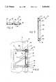
- FIG. 1is a front perspective view of an extension device according to the present invention.
- FIG. 2is a rear perspective view of the extension device shown in FIG. 1.
- FIG. 3is a front elevational view of the extension device.
- FIG. 4is a cross-section of the extension device drawn along the line 4--4 of FIG. 3.
- FIG. 5is a cross-section of the extension device drawn along the line 5--5 of FIG. 3.
- FIG. 6is an environmental cross-sectional view of the extension device.
- FIG. 7is an environmental front elevational view of the extension device used with a metal single-gang box.
- FIG. 8is an environmental front elevational view of the extension device used with a plastic single-gang box.
- the extension device 10is comprised of a substantially rectangular ring 12 having peripheral walls 14, 16 carrying dimensions approximating the peripheral walls W 1 , W 2 of an existing electrical box B, as is shown in FIG. 6.
- a peripheral flange 18extends inwardly and substantially perpendicularly from the rearward most edge of the peripheral walls forming the rectangular ring 12.
- the right angle structure formed by the peripheral walls W 1 , W 2enhance the structural integrity of the ring 12.
- An upper and lower formation 20each extend inwardly from a central point located interiorly of the upper and lower peripheral walls 14 of the rectangular ring 12.
- the extension device 10is fabricated of non-conductive material, such as a molded plastic or a hardened rubber.
- the extension device 10is for use with existing electrical boxes B.
- the extension device 10is for use in mounting electrical devices D flush with a finished surface S of a new wall covering N applied over an existing wall covering E.
- the extension device 10isolates the electrical device D from its surrounding environment.
- the peripheral flange 18is arranged and configured so as to abut the peripheral walls W 1 , W 2 of the existing electrical box B.
- the inwardly directed peripheral flange 18permits the same extension device 10 to abut the peripheral walls of existing electrical boxes of various types and configurations, such as the metal single-gang box B 1 shown in FIG. 7, and the plastic single-gang box B 2 shown in FIG. 8.
- the isolation of the electrical device D and its associated circuitry Ccould not be achieved with a single extension.
- a different extensionwould be required depending on the type and configuration of the box.
- the inwardly directed formations 20are provided with openings 22 so as to form ferrules.
- the openings 22are oriented so as to be permitted to coalign with the threaded apertures T in the existing electrical box B.
- the threaded apertures Tmate with threaded fasteners F which fasten the electrical device D to the existing electrical box B.
- the electrical device Dmay be passed through the extension device 10.
- the electrical device Dmay be passed through the extension device without disconnecting the associated circuitry C.
- the extension device 10since the extension device 10 is fabricated of the nonconductive and noncombustible material, it reduces the risk of potential fire hazard and personal injury which may occur if the extension device 10 is installed without eliminating power from the electrical circuitry C.
- the extension device 10may be inserted into the hole H formed in the new wall covering N in such a manner that the peripheral flange 18 abuts the existing electrical box B.
- the electrical device 10may be secured flush with the finished surface S of the new wall covering N.
- the extension device 10is sandwiched between the electrical device D and the existing electrical box B.
- the same threaded fasteners F which fasten the electrical device D to the existing electrical box Bsecure the extension device 10 against the electrical box B. It may be necessary to replace the original or existing fasteners F with longer fasteners, depending on the thickness of the new wall covering N and, likewise, the thickness of the extension device 10. Otherwise, no additional hardware is required. A minimal installation effort is achieved.
- the extension device 10can be dimensioned and configured to be used with a myriad of existing electrical boxes B, such as the 2 ⁇ 4 inch single-gang box shown or any of a number of multi-ganged boxes (i.e. 4 ⁇ 4 two-gang and 6 ⁇ 4 inch three-gang boxes). It should further be understood that the extension device 10 may be dimensioned so as to be useful in holes H of varying depth (i.e. 3/8, 1/2, 5/8, and 3/4 inch deep holes). It should also be understood that the extension device 10 may be stackable. By stacking various extension devices 10, a desired extension may be achieved.
Landscapes
- Engineering & Computer Science (AREA)
- Architecture (AREA)
- Civil Engineering (AREA)
- Structural Engineering (AREA)
- Casings For Electric Apparatus (AREA)
- Connection Or Junction Boxes (AREA)
Abstract
Description
This is a continuation-in-part of application Ser. No. 07/959,640, filed on Oct. 13, 1992, abandoned.
1. Field of the Invention
The present invention relates to a wall outlet box extension or an extension for use with existing electrical boxes. Such an extension would be ideal when a new surface, such as drywall or paneling, has been installed over an existing surface.
2. Description of the Prior Art
Electrical boxes are used in electrical construction to isolate electrical devices and the circuitry associated therewith from a surrounding environment. A single gang electrical box (5) of metallic construction is shown in U.S. Pat. No. 2,378,861, issued Jun. 19, 1945 to Lafayette H. Peevey. A two-gang electrical box (10) is shown in U.S. Pat. No. 2,989,206, issued Jun. 20, 1961 to R. F. McAfee. An electrical box constructed of phenolic resin or similar insulation hard plastic material is shown in U.S. Pat. No. 3,119,895 issued Jan. 28, 1964 to Lewis E. Palmer. During the course of new construction, electrical boxes such as these are permanently mounted to the building structure so as to extend flush with the finished surface of the wall.
When rehabilitating or remodeling a building, it is often desirable to install a new wall covering or surface over an existing wall covering or surface as opposed to removing and replacing the existing surface. Holes are easily cut in the new wall covering which align with existing electrical boxes. However, when the installation of the new wall covering is completed, the existing electrical boxes no longer extend flush with the finished surface thereof but are set back within the finished surface. This poses a problem. In order to meet National Electrical Codes, the electrical boxes must extend flush with the new finished surface. Moving the electrical boxes is time consuming and hence, not a practical solution to this problem.
Extension devices have been devised which extend to the finished surface of the new wall covering and thus, compensate for the installation of the new wall covering over the existing wall covering. One such extension device is shown, for example, in U.S. Pat. No. 3,878,315, issued Apr. 15, 1975 to Jerry F. Blush. Blush discloses an extension attachable to an electrical box. The extension is secured between the electrical box and the electrical device by the screws provided with the electrical device. The walls forming the extension coexist with the walls of the electrical box to which it is attached. This extension does not provide a seal with the electrical box. The extension may be disassembled and reassembled to fit electrical boxes of various sizes.
Another electrical box extension is shown in U.S. Pat. No. 2,378,861, issued Jun. 19, 1945 to Lafayette H. Peevey. The extension snugly telescopes within the electrical box. Central elongated slots are provided in the ends walls of the extension for receive the electrical box lugs. Removable sections are provided which enable the depth of the slots to be increased. This extension is limited in its application to the type of electrical box in which it may cooperatively engage.
Another telescoping electrical box extension is shown in U.S. Pat. No. 5,042,673 issued Aug. 27, 1991 to William J. McShane. McShane discloses an extension attachable to an existing electrical box so as to extend flush with a new wall surface or covering which has been applied over an existing wall surface or covering. The extension disclosed requires the use of depth adjustment screws and attachment bars to enable the electrical box extension to be mounted to an existing electrical box.
A telescoping electrical box is shown in U.S. Pat. No. 2,297,862, issued Oct. 6, 1942 to Walter H. Bachmann. Bachmann discloses an electrical box consisting of a first section and a second section slidably received by the first section. The first section includes an upper and lower ratchet surface. The second section includes an upper and lower tongue and pawl arrangement engageable with respective ratchet surfaces. The second section, or the telescoping section, limited in its application to the first section of the electrical box in which it is slidably received.
Other electrical box extensions are shown in U.S. Pat. No. 2,989,206, issued Jun. 20, 1961 to Robert F. McAfee, U.S. Pat. No. 3,525,450, issued Aug. 25, 1970 to Benjamin Payson, and U.S. Pat. No. 3,651,245, issued Mar. 21, 1972 to Oswin C. Moll. McAfee discloses an extension including a cover attachable to an electrical box. The cover has an opening therein through which a tunnel member telescopes. The tunnel member is composed of a plurality of breakaway sections which, upon removal, vary the tunnel member length. Payson and Moll each disclose an extension including a cover attachable to an electrical box. Each cover has an a sleeve or a tubular member secured thereto. Similar to McAfee, each sleeve is formed of a plurality of separable sections. Upon removal of a section, the sleeve length is shortened. Similar to that disclosed by McAfee, Payson, and Moll, is an electrical box assembly shown in U.S. Pat. No. 4,599,485, issued Jul. 8, 1986 to Robert A. Smolik. The assembly includes a tubular frame having flange members extending therefrom. The flange members cover portions of the electrical box opening not covered by the tubular frame.
In contrast to the foregoing inventions, an extension connector for an electrical box is shown in U.S. Pat. No. 3,689,864, issued Sep. 15, 1972 to James Glader, who describes an extension connector for an electrical outlet box. This extension connector is purposed to secure an electrical device flush with a new wall surface. This extension connector does not overcome a crucial problem. It does not isolate the electrical device from the environment surrounding the electrical box. A portion of the electrical device which extends between the new wall covering and the existing electrical box remains exposed.
An extension device which could be installed without removing a respective electrical device from its circuit, which could be secured to the electrical box by the same fasteners used to secure the electrical device flush with the surface of the new wall covering, and hence, which would require minimal installation effort, could prove to be invaluable.
None of the above inventions and patents, taken either singly or in combination, is seen to describe the instant invention as claimed.
The present invention is an extension device for use with existing electrical boxes. The extension device is adapted for use in mounting electrical devices flush with a finished surface of a new wall covering which has been installed over an existing wall covering. The extension device isolates the electrical device from the environment surrounding the electrical box.
The extension device is a substantially rectangular ring having peripheral walls approximating the dimensions of the peripheral walls of the existing electrical box. A peripheral flange extends inwardly and substantially perpendicularly from the four peripheral walls forming the rectangular ring. An upper and lower inwardly directed formation each extend from interiorly of a central point of the upper and lower peripheral walls forming the rectangular ring. Each formation constitutes a ferrule for receiving a threaded fastener therethrough.
The peripheral flanges are arranged and configured to abut the peripheral walls of the existing electrical box. This abutment isolates the electrical device and the electrical circuitry associated therewith within the extension and the existing electrical box. The abutment of the peripheral flanges and the peripheral walls of the existing electrical box further reduces the risk of fire hazard by isolating the electrical device and its associated electrical circuitry from the environment surrounding the extension device and the existing electrical box.
The inwardly directed formations are provided with openings which are arranged to coalign with the threaded apertures associated with the existing electrical box. The threaded apertures associated with the electrical box are arranged to receive the threaded fasteners associated with the electrical device. The threaded fasteners associated with the electrical device are intended to secure the electrical device to the existing electrical box. By removing the threaded fasteners, the electrical device may be passed through the extension device.
Subsequent to applying a new wall covering over an existing wall covering, the extension device is inserted into the hole provided in the surface of the new wall covering. The hole the surface of the new wall covering exposes the existing electrical box. Upon insertion of the extension device into the hole, the peripheral flanges abut the peripheral walls of the existing electrical box. This abutment isolates the electrical device and the electrical circuitry associated therewith from the surrounding environment thereof. With the extension device inserted into the hole and positioned adjacent to the existing electrical box, the electrical device may be secured flush with the finished surface of the new wall covering. This secures the extension device between the electrical device and the existing electrical box.
Note that the threaded fasteners which fasten the electrical device to the existing electrical box also secure the extension device in place. No additional hardware is required. Minimal installation effort is achieved.
Accordingly, it is a principal object of the invention to provide an extension device adapted for use in mounting electrical devices flush with a finished surface of a new wall covering which has been installed over an existing wall covering, and for isolating the electrical device from its surrounding environment.
It is another object that the extension device carrying dimensions approximating those of the existing electrical box.
It is a further object that the extension device abut the existing electrical box so as to isolate the electrical device and the electrical circuitry associated therewith from the surrounding environment thereof.
Still another object is that the extension device be installable without disconnecting the electrical device its associated electrical circuitry.
Another object is that the extension device be securable between the electrical device and the existing electrical box by the same threaded fasteners provided for fastening the electrical device to the existing electrical box, thus eliminating the need for additional hardware.
Yet, another object is that the extension device require a nominal amount of installation effort.
It is an object of the invention to provide improved elements and arrangements thereof in an apparatus for the purposes described which is inexpensive, dependable and fully effective in accomplishing its intended purposes.
These and other objects of the present invention will become readily apparent upon further review of the following specification and drawings.
FIG. 1 is a front perspective view of an extension device according to the present invention.
FIG. 2 is a rear perspective view of the extension device shown in FIG. 1.
FIG. 3 is a front elevational view of the extension device.
FIG. 4 is a cross-section of the extension device drawn along the line 4--4 of FIG. 3.
FIG. 5 is a cross-section of the extension device drawn along theline 5--5 of FIG. 3.
FIG. 6 is an environmental cross-sectional view of the extension device.
FIG. 7 is an environmental front elevational view of the extension device used with a metal single-gang box.
FIG. 8 is an environmental front elevational view of the extension device used with a plastic single-gang box.
Similar reference characters denote corresponding features consistently throughout the attached drawings.
Now referring to the drawings and, more particularly to FIGS. 1-5, anovel extension device 10 is illustrated. Theextension device 10 is comprised of a substantiallyrectangular ring 12 havingperipheral walls peripheral flange 18 extends inwardly and substantially perpendicularly from the rearward most edge of the peripheral walls forming therectangular ring 12. The right angle structure formed by the peripheral walls W1, W2 enhance the structural integrity of thering 12. An upper andlower formation 20 each extend inwardly from a central point located interiorly of the upper and lowerperipheral walls 14 of therectangular ring 12. Theextension device 10 is fabricated of non-conductive material, such as a molded plastic or a hardened rubber.
As shown in FIG. 6, theextension device 10 is for use with existing electrical boxes B. Theextension device 10 is for use in mounting electrical devices D flush with a finished surface S of a new wall covering N applied over an existing wall covering E. Theextension device 10 isolates the electrical device D from its surrounding environment. Theperipheral flange 18 is arranged and configured so as to abut the peripheral walls W1, W2 of the existing electrical box B. The inwardly directedperipheral flange 18 permits thesame extension device 10 to abut the peripheral walls of existing electrical boxes of various types and configurations, such as the metal single-gang box B1 shown in FIG. 7, and the plastic single-gang box B2 shown in FIG. 8. In absence of theperipheral flange 18, the isolation of the electrical device D and its associated circuitry C could not be achieved with a single extension. A different extension would be required depending on the type and configuration of the box.
The inwardly directedformations 20 are provided withopenings 22 so as to form ferrules. Theopenings 22 are oriented so as to be permitted to coalign with the threaded apertures T in the existing electrical box B. The threaded apertures T mate with threaded fasteners F which fasten the electrical device D to the existing electrical box B. By removing the threaded fasteners F from the threaded apertures T, the electrical device D may be passed through theextension device 10. The electrical device D may be passed through the extension device without disconnecting the associated circuitry C. Moreover, since theextension device 10 is fabricated of the nonconductive and noncombustible material, it reduces the risk of potential fire hazard and personal injury which may occur if theextension device 10 is installed without eliminating power from the electrical circuitry C.
After passing the electrical device D through theextension device 10, theextension device 10 may be inserted into the hole H formed in the new wall covering N in such a manner that theperipheral flange 18 abuts the existing electrical box B. Upon insertion of theextension device 10 into the hole H, as is shown in FIG. 6, theelectrical device 10 may be secured flush with the finished surface S of the new wall covering N. In this way, theextension device 10 is sandwiched between the electrical device D and the existing electrical box B. The same threaded fasteners F which fasten the electrical device D to the existing electrical box B secure theextension device 10 against the electrical box B. It may be necessary to replace the original or existing fasteners F with longer fasteners, depending on the thickness of the new wall covering N and, likewise, the thickness of theextension device 10. Otherwise, no additional hardware is required. A minimal installation effort is achieved.
It should be understood that theextension device 10 can be dimensioned and configured to be used with a myriad of existing electrical boxes B, such as the 2×4 inch single-gang box shown or any of a number of multi-ganged boxes (i.e. 4×4 two-gang and 6×4 inch three-gang boxes). It should further be understood that theextension device 10 may be dimensioned so as to be useful in holes H of varying depth (i.e. 3/8, 1/2, 5/8, and 3/4 inch deep holes). It should also be understood that theextension device 10 may be stackable. By stackingvarious extension devices 10, a desired extension may be achieved.
It is to be understood that the present invention is not limited to the sole embodiment described above, but encompasses any and all embodiments within the scope of the following claims.
Claims (7)
1. An extension for use with existing electrical boxes for mounting electrical devices flush with a finished surface of a new wall covering which has been applied over an existing wall covering and for insulating the electrical device from a surrounding environment, said extension comprising:
a ring having a plurality of peripheral walls, said peripheral walls having a rearward edge, and a forward edge, said peripheral walls being dimensioned and configured to extend between an existing electrical box and a finished surface of a new wall covering, and said rearward and forward edges having flat surfaces;
a peripheral flange extending inwardly and substantially perpendicularly from said rearward edge of said peripheral walls, said flange having a flat rearward surface;
a plurality of ferrules integral with and extending inwardly from said peripheral walls of said ring, and extending from said forward edge to said rearward edge of said peripheral walls, each ferrule having an opening passing therethrough;
said openings being arranged so as to align with threaded apertures in the existing electrical box, the threaded apertures being threadably engageable with threaded fasteners which fasten the electrical device to the existing electrical box, and said openings in said ferrules having a diameter greater than that of the threaded fastener; whereby
said electrical device is mounted flush with a surface of a new wall covering, securing said extension between the electrical device and the existing electrical box.
2. The extension according to claim 1, wherein said ring is substantially rectangular in shape, having dimensions substantially equivalent to that of a front end of an existing electrical box.
3. The extension according to claim 2, wherein said substantially rectangular ring includes upper and lower peripheral walls, and side peripheral walls.
4. The extension according to claim 3, wherein two ferrules are integral with said peripheral walls, one of said two ferrules extending from said upper peripheral wall, the other of said two ferrules extending from said lower peripheral wall.
5. The extension according to claim 4, wherein said extension is fabricated from a non-conductive material.
6. The extension according to claim 5, wherein said extension is fabricated from a molded plastic material.
7. The extension according to claim 6, wherein said extension is fabricated from a hardened rubber material.
Priority Applications (1)
| Application Number | Priority Date | Filing Date | Title |
|---|---|---|---|
| US08/154,491US5402902A (en) | 1992-10-13 | 1993-11-19 | Wall outlet box extension |
Applications Claiming Priority (2)
| Application Number | Priority Date | Filing Date | Title |
|---|---|---|---|
| US95964092A | 1992-10-13 | 1992-10-13 | |
| US08/154,491US5402902A (en) | 1992-10-13 | 1993-11-19 | Wall outlet box extension |
Related Parent Applications (1)
| Application Number | Title | Priority Date | Filing Date |
|---|---|---|---|
| US95964092AContinuation-In-Part | 1992-10-13 | 1992-10-13 |
Publications (1)
| Publication Number | Publication Date |
|---|---|
| US5402902Atrue US5402902A (en) | 1995-04-04 |
Family
ID=25502244
Family Applications (1)
| Application Number | Title | Priority Date | Filing Date |
|---|---|---|---|
| US08/154,491Expired - LifetimeUS5402902A (en) | 1992-10-13 | 1993-11-19 | Wall outlet box extension |
Country Status (1)
| Country | Link |
|---|---|
| US (1) | US5402902A (en) |
Cited By (37)
| Publication number | Priority date | Publication date | Assignee | Title |
|---|---|---|---|---|
| GB2324205A (en)* | 1995-11-22 | 1998-10-14 | Abb Patent Gmbh | Adjustable mounting of socket outlet in electrical accessory box |
| US5906287A (en)* | 1994-10-03 | 1999-05-25 | Kohnen; Stephen J. | Junction box construction for use in curved structures |
| US5910642A (en)* | 1997-08-29 | 1999-06-08 | Lucent Technologies Inc. | Expandable enclosure for telecommunications applications |
| US5975323A (en)* | 1997-10-17 | 1999-11-02 | Turan; Scott R. | Extender for electrical box |
| US6395984B1 (en)* | 2000-11-29 | 2002-05-28 | William J. Gilleran | Sub exterior weather-proof flashing panel mount for electrical junction box |
| WO2003023927A1 (en)* | 2001-09-06 | 2003-03-20 | Herman Cardenas | Structured wiring box |
| US20030116341A1 (en)* | 2000-11-29 | 2003-06-26 | Gilleran William J. | Exterior electrical box waterproofing system |
| US20040045960A1 (en)* | 2002-09-09 | 2004-03-11 | Rose Frank P. | Universal junction box |
| US20050025162A1 (en)* | 2002-11-13 | 2005-02-03 | Yehuda Binder | Addressable outlet, and a network using same |
| US20050082079A1 (en)* | 2002-04-04 | 2005-04-21 | Wegner Wesley G. | Electrical box extension |
| US20050102913A1 (en)* | 2003-10-29 | 2005-05-19 | Gilleran William J. | Air conditioning line flashing panel |
| US20050111636A1 (en)* | 1999-07-20 | 2005-05-26 | Serconet, Ltd | Network for telephony and data communication |
| US20050180561A1 (en)* | 2004-02-16 | 2005-08-18 | Serconet Ltd. | Outlet add-on module |
| US20050194172A1 (en)* | 2004-03-05 | 2005-09-08 | Ungerman Mark E. | Electric box extender |
| US20050200284A1 (en)* | 2004-03-09 | 2005-09-15 | Edgecom | An apparatus that enables low cost installation of a secure and tamper proof assembly that accommodates lifeline support for power line communication devices. |
| US20060018338A1 (en)* | 1998-07-28 | 2006-01-26 | Serconet, Ltd. | Local area network of serial intelligent cells |
| US20060043796A1 (en)* | 2004-09-02 | 2006-03-02 | Biskup James H Sr | AC wall receptacle with integral DC power supply |
| US20060123711A1 (en)* | 2003-10-29 | 2006-06-15 | Gilleran William J | Air conditioning line flashing panel |
| US20060182094A1 (en)* | 2000-04-18 | 2006-08-17 | Serconet Ltd. | Telephone communication system over a single telephone line |
| US20060197428A1 (en)* | 2005-02-21 | 2006-09-07 | Takeshi Tonegawa | Electron devices with non-evaporation-type getters and method for manufacturing the same |
| US20070019669A1 (en)* | 2003-07-09 | 2007-01-25 | Serconet Ltd. | Modular outlet |
| US20070045308A1 (en)* | 2005-08-31 | 2007-03-01 | Thomas & Betts International, Inc. | Pull out extension contained in electrical box |
| US20070107924A1 (en)* | 2005-11-14 | 2007-05-17 | The Patent Store Llc | Box extender |
| US7273982B1 (en)* | 2006-12-22 | 2007-09-25 | Thomas & Betts International, Inc. | Electrical box extender mechanical fastener |
| US20080156513A1 (en)* | 2007-01-03 | 2008-07-03 | Johnson Steven J | Electrical box mounting plate with adjustable ring |
| US7453895B2 (en) | 2001-10-11 | 2008-11-18 | Serconet Ltd | Outlet with analog signal adapter, a method for use thereof and a network using said outlet |
| GB2457520A (en)* | 2008-02-14 | 2009-08-19 | Richard David Brook | Safety shield for electrical back box |
| US7680255B2 (en) | 2001-07-05 | 2010-03-16 | Mosaid Technologies Incorporated | Telephone outlet with packet telephony adaptor, and a network using same |
| US7873058B2 (en) | 2004-11-08 | 2011-01-18 | Mosaid Technologies Incorporated | Outlet with analog signal adapter, a method for use thereof and a network using said outlet |
| US8582598B2 (en) | 1999-07-07 | 2013-11-12 | Mosaid Technologies Incorporated | Local area network for distributing data communication, sensing and control signals |
| US8748744B2 (en) | 2012-06-28 | 2014-06-10 | Hubbell Incorporated | Electrical box extender assembly |
| US8933331B1 (en)* | 2012-11-19 | 2015-01-13 | Arlington Industries, Inc. | Reversible electrical box assembly with extensions to match various reveals |
| US9806507B2 (en) | 2015-08-03 | 2017-10-31 | Phillip J. Gross | Modular electrical box extender |
| US10132084B2 (en) | 2013-03-15 | 2018-11-20 | Wjg, Llc | Single wall duct flashing panel |
| US10986165B2 (en) | 2004-01-13 | 2021-04-20 | May Patents Ltd. | Information device |
| USD1087923S1 (en)* | 2022-12-05 | 2025-08-12 | Eaton Intelligent Power Limited | Adjustable mudring |
| US12401179B1 (en)* | 2023-02-24 | 2025-08-26 | S&C Manufacturing LLC | Electrical box spacer |
Citations (13)
| Publication number | Priority date | Publication date | Assignee | Title |
|---|---|---|---|---|
| US2297862A (en)* | 1939-08-30 | 1942-10-06 | Walter H Bachmann | Switch box |
| US2378861A (en)* | 1944-04-20 | 1945-06-19 | Lafayette H Peevey | Outlet box extension |
| US2989206A (en)* | 1960-06-01 | 1961-06-20 | Robert F Mcafee | Outlet box extension |
| US3525450A (en)* | 1968-12-23 | 1970-08-25 | Benjamin Payson | Electrical box cover construction |
| US3651245A (en)* | 1969-12-22 | 1972-03-21 | Oswin C Moll | Junction box and grounding means therefor |
| US3689864A (en)* | 1971-06-24 | 1972-09-05 | James Glader | Extension connector for electrical outlet box |
| US3878315A (en)* | 1973-01-24 | 1975-04-15 | Jerry F Blush | Attachable extension for an electrical outlet housing |
| US3955701A (en)* | 1975-04-21 | 1976-05-11 | Reinhold Fisch | Universal extension for outlet boxes |
| US4599485A (en)* | 1984-12-21 | 1986-07-08 | Smolik Robert A | Electrical receptacle box assembly |
| US4634015A (en)* | 1985-07-15 | 1987-01-06 | Taylor Jerald M | Adjustable electric outlet box |
| US4927039A (en)* | 1989-07-12 | 1990-05-22 | Viscount Industries Limited | Electrical box |
| US5042673A (en)* | 1989-06-22 | 1991-08-27 | Mcshane William J | Electric box extension |
| US5117996A (en)* | 1989-06-22 | 1992-06-02 | Mcshane William J | Electrical box extension |
- 1993
- 1993-11-19USUS08/154,491patent/US5402902A/ennot_activeExpired - Lifetime
Patent Citations (13)
| Publication number | Priority date | Publication date | Assignee | Title |
|---|---|---|---|---|
| US2297862A (en)* | 1939-08-30 | 1942-10-06 | Walter H Bachmann | Switch box |
| US2378861A (en)* | 1944-04-20 | 1945-06-19 | Lafayette H Peevey | Outlet box extension |
| US2989206A (en)* | 1960-06-01 | 1961-06-20 | Robert F Mcafee | Outlet box extension |
| US3525450A (en)* | 1968-12-23 | 1970-08-25 | Benjamin Payson | Electrical box cover construction |
| US3651245A (en)* | 1969-12-22 | 1972-03-21 | Oswin C Moll | Junction box and grounding means therefor |
| US3689864A (en)* | 1971-06-24 | 1972-09-05 | James Glader | Extension connector for electrical outlet box |
| US3878315A (en)* | 1973-01-24 | 1975-04-15 | Jerry F Blush | Attachable extension for an electrical outlet housing |
| US3955701A (en)* | 1975-04-21 | 1976-05-11 | Reinhold Fisch | Universal extension for outlet boxes |
| US4599485A (en)* | 1984-12-21 | 1986-07-08 | Smolik Robert A | Electrical receptacle box assembly |
| US4634015A (en)* | 1985-07-15 | 1987-01-06 | Taylor Jerald M | Adjustable electric outlet box |
| US5042673A (en)* | 1989-06-22 | 1991-08-27 | Mcshane William J | Electric box extension |
| US5117996A (en)* | 1989-06-22 | 1992-06-02 | Mcshane William J | Electrical box extension |
| US4927039A (en)* | 1989-07-12 | 1990-05-22 | Viscount Industries Limited | Electrical box |
Cited By (112)
| Publication number | Priority date | Publication date | Assignee | Title |
|---|---|---|---|---|
| US5906287A (en)* | 1994-10-03 | 1999-05-25 | Kohnen; Stephen J. | Junction box construction for use in curved structures |
| US6098825A (en)* | 1994-10-03 | 2000-08-08 | Kohnen; Stephen J. | Junction box construction for use in curved structures |
| GB2324205A (en)* | 1995-11-22 | 1998-10-14 | Abb Patent Gmbh | Adjustable mounting of socket outlet in electrical accessory box |
| GB2324205B (en)* | 1995-11-22 | 2001-09-05 | Abb Patent Gmbh | Electrical installation |
| US5910642A (en)* | 1997-08-29 | 1999-06-08 | Lucent Technologies Inc. | Expandable enclosure for telecommunications applications |
| US5975323A (en)* | 1997-10-17 | 1999-11-02 | Turan; Scott R. | Extender for electrical box |
| US7986708B2 (en) | 1998-07-28 | 2011-07-26 | Mosaid Technologies Incorporated | Local area network of serial intelligent cells |
| US8908673B2 (en) | 1998-07-28 | 2014-12-09 | Conversant Intellectual Property Management Incorporated | Local area network of serial intelligent cells |
| US7965735B2 (en) | 1998-07-28 | 2011-06-21 | Mosaid Technologies Incorporated | Local area network of serial intelligent cells |
| US7221679B2 (en) | 1998-07-28 | 2007-05-22 | Serconet Ltd. | Local area network of serial intelligent cells |
| US8867523B2 (en) | 1998-07-28 | 2014-10-21 | Conversant Intellectual Property Management Incorporated | Local area network of serial intelligent cells |
| US20060018338A1 (en)* | 1998-07-28 | 2006-01-26 | Serconet, Ltd. | Local area network of serial intelligent cells |
| US8885659B2 (en) | 1998-07-28 | 2014-11-11 | Conversant Intellectual Property Management Incorporated | Local area network of serial intelligent cells |
| US8885660B2 (en) | 1998-07-28 | 2014-11-11 | Conversant Intellectual Property Management Incorporated | Local area network of serial intelligent cells |
| US8582598B2 (en) | 1999-07-07 | 2013-11-12 | Mosaid Technologies Incorporated | Local area network for distributing data communication, sensing and control signals |
| US7483524B2 (en) | 1999-07-20 | 2009-01-27 | Serconet, Ltd | Network for telephony and data communication |
| US8351582B2 (en) | 1999-07-20 | 2013-01-08 | Mosaid Technologies Incorporated | Network for telephony and data communication |
| US20050111636A1 (en)* | 1999-07-20 | 2005-05-26 | Serconet, Ltd | Network for telephony and data communication |
| US8929523B2 (en) | 1999-07-20 | 2015-01-06 | Conversant Intellectual Property Management Inc. | Network for telephony and data communication |
| US7466722B2 (en) | 2000-04-18 | 2008-12-16 | Serconet Ltd | Telephone communication system over a single telephone line |
| US8559422B2 (en) | 2000-04-18 | 2013-10-15 | Mosaid Technologies Incorporated | Telephone communication system over a single telephone line |
| US8000349B2 (en) | 2000-04-18 | 2011-08-16 | Mosaid Technologies Incorporated | Telephone communication system over a single telephone line |
| US7397791B2 (en) | 2000-04-18 | 2008-07-08 | Serconet, Ltd. | Telephone communication system over a single telephone line |
| US20080043646A1 (en)* | 2000-04-18 | 2008-02-21 | Serconet Ltd. | Telephone communication system over a single telephone line |
| US7593394B2 (en) | 2000-04-18 | 2009-09-22 | Mosaid Technologies Incorporated | Telephone communication system over a single telephone line |
| US8223800B2 (en) | 2000-04-18 | 2012-07-17 | Mosaid Technologies Incorporated | Telephone communication system over a single telephone line |
| US7197028B2 (en) | 2000-04-18 | 2007-03-27 | Serconet Ltd. | Telephone communication system over a single telephone line |
| US20060182094A1 (en)* | 2000-04-18 | 2006-08-17 | Serconet Ltd. | Telephone communication system over a single telephone line |
| US6395984B1 (en)* | 2000-11-29 | 2002-05-28 | William J. Gilleran | Sub exterior weather-proof flashing panel mount for electrical junction box |
| US6649835B2 (en) | 2000-11-29 | 2003-11-18 | William J. Gilleran | Sub-exterior electrical box waterproofing system |
| US20030116341A1 (en)* | 2000-11-29 | 2003-06-26 | Gilleran William J. | Exterior electrical box waterproofing system |
| US6596938B2 (en)* | 2000-11-29 | 2003-07-22 | William J. Gilleran | Exterior electrical box waterproofing system |
| US7680255B2 (en) | 2001-07-05 | 2010-03-16 | Mosaid Technologies Incorporated | Telephone outlet with packet telephony adaptor, and a network using same |
| WO2003023927A1 (en)* | 2001-09-06 | 2003-03-20 | Herman Cardenas | Structured wiring box |
| US7860084B2 (en) | 2001-10-11 | 2010-12-28 | Mosaid Technologies Incorporated | Outlet with analog signal adapter, a method for use thereof and a network using said outlet |
| US7453895B2 (en) | 2001-10-11 | 2008-11-18 | Serconet Ltd | Outlet with analog signal adapter, a method for use thereof and a network using said outlet |
| US7953071B2 (en) | 2001-10-11 | 2011-05-31 | Mosaid Technologies Incorporated | Outlet with analog signal adapter, a method for use thereof and a network using said outlet |
| US7889720B2 (en) | 2001-10-11 | 2011-02-15 | Mosaid Technologies Incorporated | Outlet with analog signal adapter, a method for use thereof and a network using said outlet |
| US20050224249A2 (en)* | 2002-04-04 | 2005-10-13 | Wegner Wesley G | Electrical box extension |
| US7410072B2 (en)* | 2002-04-04 | 2008-08-12 | Wesley Gene Wegner | Electrical box extension |
| US20080047729A1 (en)* | 2002-04-04 | 2008-02-28 | Wegner Wesley G | Electrical Box Extension |
| US7637385B2 (en)* | 2002-04-04 | 2009-12-29 | Wesley Gene Wegner | Electrical box extension |
| US20050082079A1 (en)* | 2002-04-04 | 2005-04-21 | Wegner Wesley G. | Electrical box extension |
| US20100089912A1 (en)* | 2002-04-04 | 2010-04-15 | Wesley Gene Wegner | Electrical box extension |
| US7019211B2 (en) | 2002-09-09 | 2006-03-28 | Rose Frank P | Universal junction box |
| US6929140B2 (en) | 2002-09-09 | 2005-08-16 | Frank P. Rose | Universal junction box |
| US20070102181A1 (en)* | 2002-09-09 | 2007-05-10 | Rose Frank P | Universal Junction Box with Mounting Aperture |
| US7179993B2 (en) | 2002-09-09 | 2007-02-20 | Rose Frank P | Universal junction box with mounting aperture |
| US20050217887A1 (en)* | 2002-09-09 | 2005-10-06 | Rose Frank P | Universal junction box |
| US20040045960A1 (en)* | 2002-09-09 | 2004-03-11 | Rose Frank P. | Universal junction box |
| US20060175072A1 (en)* | 2002-09-09 | 2006-08-10 | Rose Frank P | Universal junction box with mounting aperture |
| US7522615B2 (en) | 2002-11-13 | 2009-04-21 | Serconet, Ltd. | Addressable outlet, and a network using same |
| US8295185B2 (en) | 2002-11-13 | 2012-10-23 | Mosaid Technologies Inc. | Addressable outlet for use in wired local area network |
| US20080198777A1 (en)* | 2002-11-13 | 2008-08-21 | Serconet Ltd. | Addressable outlet, and a network using the same |
| US7911992B2 (en) | 2002-11-13 | 2011-03-22 | Mosaid Technologies Incorporated | Addressable outlet, and a network using the same |
| US7990908B2 (en) | 2002-11-13 | 2011-08-02 | Mosaid Technologies Incorporated | Addressable outlet, and a network using the same |
| US20050025162A1 (en)* | 2002-11-13 | 2005-02-03 | Yehuda Binder | Addressable outlet, and a network using same |
| US20070019669A1 (en)* | 2003-07-09 | 2007-01-25 | Serconet Ltd. | Modular outlet |
| US7688841B2 (en) | 2003-07-09 | 2010-03-30 | Mosaid Technologies Incorporated | Modular outlet |
| US7873062B2 (en) | 2003-07-09 | 2011-01-18 | Mosaid Technologies Incorporated | Modular outlet |
| US7867035B2 (en) | 2003-07-09 | 2011-01-11 | Mosaid Technologies Incorporated | Modular outlet |
| US8092258B2 (en) | 2003-09-07 | 2012-01-10 | Mosaid Technologies Incorporated | Modular outlet |
| US8591264B2 (en) | 2003-09-07 | 2013-11-26 | Mosaid Technologies Incorporated | Modular outlet |
| US7690949B2 (en) | 2003-09-07 | 2010-04-06 | Mosaid Technologies Incorporated | Modular outlet |
| US8235755B2 (en) | 2003-09-07 | 2012-08-07 | Mosaid Technologies Incorporated | Modular outlet |
| US8360810B2 (en) | 2003-09-07 | 2013-01-29 | Mosaid Technologies Incorporated | Modular outlet |
| US7686653B2 (en) | 2003-09-07 | 2010-03-30 | Mosaid Technologies Incorporated | Modular outlet |
| US7305801B2 (en) | 2003-10-29 | 2007-12-11 | Gilleran William J | Air conditioning line flashing panel |
| US20060123711A1 (en)* | 2003-10-29 | 2006-06-15 | Gilleran William J | Air conditioning line flashing panel |
| US7640699B2 (en) | 2003-10-29 | 2010-01-05 | Gilleran William J | Air conditioning line flashing panel |
| US20070261327A1 (en)* | 2003-10-29 | 2007-11-15 | Gilleran William J | Air conditioning line flashing panel |
| US7389616B2 (en) | 2003-10-29 | 2008-06-24 | Gilleran William J | Air conditioning line flashing panel |
| US7730681B2 (en) | 2003-10-29 | 2010-06-08 | Gilleran William J | Air conditioning line flashing panel |
| US20050102913A1 (en)* | 2003-10-29 | 2005-05-19 | Gilleran William J. | Air conditioning line flashing panel |
| US20080148654A1 (en)* | 2003-10-29 | 2008-06-26 | Gilleran William J | Air conditioning line flashing panel |
| US10986165B2 (en) | 2004-01-13 | 2021-04-20 | May Patents Ltd. | Information device |
| US20080227333A1 (en)* | 2004-02-16 | 2008-09-18 | Serconet Ltd. | Outlet add-on module |
| US8243918B2 (en) | 2004-02-16 | 2012-08-14 | Mosaid Technologies Incorporated | Outlet add-on module |
| US20050180561A1 (en)* | 2004-02-16 | 2005-08-18 | Serconet Ltd. | Outlet add-on module |
| US7881462B2 (en) | 2004-02-16 | 2011-02-01 | Mosaid Technologies Incorporated | Outlet add-on module |
| US7756268B2 (en) | 2004-02-16 | 2010-07-13 | Mosaid Technologies Incorporated | Outlet add-on module |
| US8611528B2 (en) | 2004-02-16 | 2013-12-17 | Mosaid Technologies Incorporated | Outlet add-on module |
| US8565417B2 (en) | 2004-02-16 | 2013-10-22 | Mosaid Technologies Incorporated | Outlet add-on module |
| US8542819B2 (en) | 2004-02-16 | 2013-09-24 | Mosaid Technologies Incorporated | Outlet add-on module |
| US20080231111A1 (en)* | 2004-02-16 | 2008-09-25 | Serconet Ltd. | Outlet add-on module |
| US20080226060A1 (en)* | 2004-02-16 | 2008-09-18 | Serconet Ltd. | Outlet add-on module |
| US20080219430A1 (en)* | 2004-02-16 | 2008-09-11 | Serconet Ltd. | Outlet add-on module |
| US7002076B2 (en) | 2004-03-05 | 2006-02-21 | Bridgeport Fittings, Inc. | Electric box extender |
| US20050230139A1 (en)* | 2004-03-05 | 2005-10-20 | Ungerman Mark E | Electric box extender |
| US20050194172A1 (en)* | 2004-03-05 | 2005-09-08 | Ungerman Mark E. | Electric box extender |
| US6953894B2 (en)* | 2004-03-05 | 2005-10-11 | Bridgeport Fittings, Inc. | Electric box extender |
| US20050200284A1 (en)* | 2004-03-09 | 2005-09-15 | Edgecom | An apparatus that enables low cost installation of a secure and tamper proof assembly that accommodates lifeline support for power line communication devices. |
| US7034225B2 (en) | 2004-03-09 | 2006-04-25 | Scott Randall Thompson | Apparatus that enables low cost installation of a secure and tamper proof assembly that accommodates lifeline support for power line communication devices |
| WO2006028905A1 (en)* | 2004-09-02 | 2006-03-16 | Biskup James H | Ac wall receptacle with integral dc power supply |
| US20060043796A1 (en)* | 2004-09-02 | 2006-03-02 | Biskup James H Sr | AC wall receptacle with integral DC power supply |
| US7873058B2 (en) | 2004-11-08 | 2011-01-18 | Mosaid Technologies Incorporated | Outlet with analog signal adapter, a method for use thereof and a network using said outlet |
| US20060197428A1 (en)* | 2005-02-21 | 2006-09-07 | Takeshi Tonegawa | Electron devices with non-evaporation-type getters and method for manufacturing the same |
| US20070045308A1 (en)* | 2005-08-31 | 2007-03-01 | Thomas & Betts International, Inc. | Pull out extension contained in electrical box |
| US7757875B2 (en)* | 2005-08-31 | 2010-07-20 | Thomas & Betts International, Inc. | Pull out extension contained in electrical box |
| US20070107924A1 (en)* | 2005-11-14 | 2007-05-17 | The Patent Store Llc | Box extender |
| US7235739B2 (en)* | 2005-11-14 | 2007-06-26 | King Jr Lloyd Herbert | Box extender |
| US7273982B1 (en)* | 2006-12-22 | 2007-09-25 | Thomas & Betts International, Inc. | Electrical box extender mechanical fastener |
| US7531743B2 (en) | 2007-01-03 | 2009-05-12 | Hubbell Incorporated | Electrical box mounting plate with adjustable ring |
| US20080156513A1 (en)* | 2007-01-03 | 2008-07-03 | Johnson Steven J | Electrical box mounting plate with adjustable ring |
| GB2457520B (en)* | 2008-02-14 | 2009-12-30 | Richard David Brook | Safety shield for electrical back box |
| GB2457520A (en)* | 2008-02-14 | 2009-08-19 | Richard David Brook | Safety shield for electrical back box |
| US8748744B2 (en) | 2012-06-28 | 2014-06-10 | Hubbell Incorporated | Electrical box extender assembly |
| US8933331B1 (en)* | 2012-11-19 | 2015-01-13 | Arlington Industries, Inc. | Reversible electrical box assembly with extensions to match various reveals |
| US10132084B2 (en) | 2013-03-15 | 2018-11-20 | Wjg, Llc | Single wall duct flashing panel |
| US9806507B2 (en) | 2015-08-03 | 2017-10-31 | Phillip J. Gross | Modular electrical box extender |
| USD1087923S1 (en)* | 2022-12-05 | 2025-08-12 | Eaton Intelligent Power Limited | Adjustable mudring |
| US12401179B1 (en)* | 2023-02-24 | 2025-08-26 | S&C Manufacturing LLC | Electrical box spacer |
Similar Documents
| Publication | Publication Date | Title |
|---|---|---|
| US5402902A (en) | Wall outlet box extension | |
| US5723817A (en) | Snap-on wallplate system | |
| US5117996A (en) | Electrical box extension | |
| US4264779A (en) | Poke-through electrical fitting with releasable wedging point for retention | |
| US4098423A (en) | Self-aligning outlet box assembly | |
| US3701451A (en) | Molded electrical junction box | |
| US2297862A (en) | Switch box | |
| US5975323A (en) | Extender for electrical box | |
| US6053456A (en) | Cable anchor assembly | |
| US5931325A (en) | Adjustable mudring for conventional electrical outlet box | |
| US6858802B2 (en) | Extension ring for electrical junction box installations | |
| US5042673A (en) | Electric box extension | |
| US4087624A (en) | Fire shield for electrical box | |
| US3116563A (en) | Installation fixture | |
| US3369071A (en) | Electrical conduit connector | |
| US5740936A (en) | Electric outlet box assembly | |
| US4863399A (en) | Low voltage bracket | |
| US4456326A (en) | Wall mountable cable terminal block | |
| US4699289A (en) | Structure of switch box | |
| US5823821A (en) | Apparatus for securing an electrical outlet to an outlet box having stripped threads | |
| US2684994A (en) | Ground clamp for electrical outlet boxes and the like | |
| US3511941A (en) | Public telephone mounting | |
| EP0289816A1 (en) | Door casing for covering a door or like opening in a wall | |
| US1760663A (en) | Bushing-clamp-connecting device | |
| DE3500655A1 (en) | Housing for distributors, especially for telephone systems |
Legal Events
| Date | Code | Title | Description |
|---|---|---|---|
| AS | Assignment | Owner name:GADGET MANIA, INC., MAINE Free format text:ASSIGNMENT OF ASSIGNORS INTEREST;ASSIGNOR:BOULEY, ROGER R.;REEL/FRAME:009500/0939 Effective date:19980918 | |
| REMI | Maintenance fee reminder mailed | ||
| FP | Lapsed due to failure to pay maintenance fee | Effective date:19990404 | |
| FEPP | Fee payment procedure | Free format text:PETITION RELATED TO MAINTENANCE FEES FILED (ORIGINAL EVENT CODE: PMFP); ENTITY STATUS OF PATENT OWNER: SMALL ENTITY | |
| FEPP | Fee payment procedure | Free format text:PETITION RELATED TO MAINTENANCE FEES GRANTED (ORIGINAL EVENT CODE: PMFG); ENTITY STATUS OF PATENT OWNER: SMALL ENTITY | |
| AS | Assignment | Owner name:GADGET MANIA, INC., RHODE ISLAND Free format text:CHANGE OF ASSIGNEE ADDRESS;ASSIGNOR:GADGET MANIA, INC.;REEL/FRAME:010909/0556 Effective date:19970101 | |
| FPAY | Fee payment | Year of fee payment:4 | |
| SULP | Surcharge for late payment | ||
| STCF | Information on status: patent grant | Free format text:PATENTED CASE | |
| PRDP | Patent reinstated due to the acceptance of a late maintenance fee | Effective date:20001215 | |
| FPAY | Fee payment | Year of fee payment:8 | |
| FPAY | Fee payment | Year of fee payment:12 |