US5402772A - Endoscopic expandable retraction device - Google Patents
Endoscopic expandable retraction deviceDownload PDFInfo
- Publication number
- US5402772A US5402772AUS08/106,227US10622793AUS5402772AUS 5402772 AUS5402772 AUS 5402772AUS 10622793 AUS10622793 AUS 10622793AUS 5402772 AUS5402772 AUS 5402772A
- Authority
- US
- United States
- Prior art keywords
- retraction device
- envelope
- main
- additional
- tissue
- Prior art date
- Legal status (The legal status is an assumption and is not a legal conclusion. Google has not performed a legal analysis and makes no representation as to the accuracy of the status listed.)
- Expired - Lifetime
Links
- 210000000056organAnatomy0.000claimsabstractdescription37
- 238000000034methodMethods0.000claimsdescription120
- 239000012530fluidSubstances0.000claimsdescription8
- 210000001519tissueAnatomy0.000description76
- 210000001015abdomenAnatomy0.000description30
- 239000007789gasSubstances0.000description30
- 210000000683abdominal cavityAnatomy0.000description27
- 210000004072lungAnatomy0.000description27
- 239000000853adhesiveSubstances0.000description26
- 230000001070adhesive effectEffects0.000description26
- 239000004698PolyethyleneSubstances0.000description24
- -1polyethylenePolymers0.000description24
- 229920000573polyethylenePolymers0.000description24
- 210000003815abdominal wallAnatomy0.000description23
- 238000003466weldingMethods0.000description23
- 229920003023plasticPolymers0.000description22
- 239000004033plasticSubstances0.000description22
- 206010019909HerniaDiseases0.000description21
- 238000005304joiningMethods0.000description19
- 210000004303peritoneumAnatomy0.000description18
- 238000010276constructionMethods0.000description16
- 238000005520cutting processMethods0.000description15
- 239000002985plastic filmSubstances0.000description15
- 229920006255plastic filmPolymers0.000description15
- 210000003516pericardiumAnatomy0.000description13
- 239000000463materialSubstances0.000description12
- 210000004556brainAnatomy0.000description11
- 238000003780insertionMethods0.000description11
- 230000037431insertionEffects0.000description11
- 210000004185liverAnatomy0.000description10
- 210000004224pleuraAnatomy0.000description10
- 210000001951dura materAnatomy0.000description9
- 210000000779thoracic wallAnatomy0.000description9
- 239000004677NylonSubstances0.000description8
- 210000000038chestAnatomy0.000description8
- 239000002131composite materialSubstances0.000description8
- 229920001778nylonPolymers0.000description8
- 229920002799BoPETPolymers0.000description7
- 230000000694effectsEffects0.000description7
- 210000003238esophagusAnatomy0.000description7
- 229920002635polyurethanePolymers0.000description7
- 239000004814polyurethaneSubstances0.000description7
- CURLTUGMZLYLDI-UHFFFAOYSA-NCarbon dioxideChemical compoundO=C=OCURLTUGMZLYLDI-UHFFFAOYSA-N0.000description6
- 210000003236esophagogastric junctionAnatomy0.000description6
- 210000000232gallbladderAnatomy0.000description6
- 238000012856packingMethods0.000description6
- 210000003281pleural cavityAnatomy0.000description6
- 210000000709aortaAnatomy0.000description4
- 238000004891communicationMethods0.000description4
- 238000010438heat treatmentMethods0.000description4
- 210000003734kidneyAnatomy0.000description4
- 238000002357laparoscopic surgeryMethods0.000description4
- 210000003625skullAnatomy0.000description4
- IJGRMHOSHXDMSA-UHFFFAOYSA-NAtomic nitrogenChemical compoundN#NIJGRMHOSHXDMSA-UHFFFAOYSA-N0.000description3
- 239000004831Hot glueSubstances0.000description3
- 230000003187abdominal effectEffects0.000description3
- 239000003570airSubstances0.000description3
- 238000013459approachMethods0.000description3
- 229910002092carbon dioxideInorganic materials0.000description3
- 239000001569carbon dioxideSubstances0.000description3
- 238000006073displacement reactionMethods0.000description3
- 238000001125extrusionMethods0.000description3
- 210000003128headAnatomy0.000description3
- 208000014674injuryDiseases0.000description3
- JCXJVPUVTGWSNB-UHFFFAOYSA-Nnitrogen dioxideInorganic materialsO=[N]=OJCXJVPUVTGWSNB-UHFFFAOYSA-N0.000description3
- 238000002271resectionMethods0.000description3
- 238000001356surgical procedureMethods0.000description3
- 230000008733traumaEffects0.000description3
- 239000004820Pressure-sensitive adhesiveSubstances0.000description2
- 230000015572biosynthetic processEffects0.000description2
- 208000021302gastroesophageal reflux diseaseDiseases0.000description2
- 238000004519manufacturing processMethods0.000description2
- 238000011084recoveryMethods0.000description2
- 230000000717retained effectEffects0.000description2
- 239000000523sampleSubstances0.000description2
- 210000001186vagus nerveAnatomy0.000description2
- 229920004934Dacron®Polymers0.000description1
- 208000007536ThrombosisDiseases0.000description1
- 238000002679ablationMethods0.000description1
- 239000003522acrylic cementSubstances0.000description1
- 230000000740bleeding effectEffects0.000description1
- 238000007664blowingMethods0.000description1
- 238000007796conventional methodMethods0.000description1
- 229920001971elastomerPolymers0.000description1
- 239000013536elastomeric materialSubstances0.000description1
- 229920002457flexible plasticPolymers0.000description1
- 239000003292glueSubstances0.000description1
- 230000002262irrigationEffects0.000description1
- 238000003973irrigationMethods0.000description1
- 230000007794irritationEffects0.000description1
- 229920000126latexPolymers0.000description1
- 239000004816latexSubstances0.000description1
- 238000013507mappingMethods0.000description1
- 229910001120nichromeInorganic materials0.000description1
- 239000003973paintSubstances0.000description1
- 230000000149penetrating effectEffects0.000description1
- 210000003200peritoneal cavityAnatomy0.000description1
- 238000002360preparation methodMethods0.000description1
- 238000003825pressingMethods0.000description1
- 210000002307prostateAnatomy0.000description1
- 230000000250revascularizationEffects0.000description1
- 210000004761scalpAnatomy0.000description1
- 238000007789sealingMethods0.000description1
- 239000013464silicone adhesiveSubstances0.000description1
- 229920002379silicone rubberPolymers0.000description1
- 239000004945silicone rubberSubstances0.000description1
- 229910001220stainless steelInorganic materials0.000description1
- 239000010935stainless steelSubstances0.000description1
- 230000001954sterilising effectEffects0.000description1
- 238000004659sterilization and disinfectionMethods0.000description1
- 210000002784stomachAnatomy0.000description1
- 210000001113umbilicusAnatomy0.000description1
- 210000001835visceraAnatomy0.000description1
Images


Classifications
- A—HUMAN NECESSITIES
- A61—MEDICAL OR VETERINARY SCIENCE; HYGIENE
- A61B—DIAGNOSIS; SURGERY; IDENTIFICATION
- A61B17/00—Surgical instruments, devices or methods
- A61B17/34—Trocars; Puncturing needles
- A61B17/3417—Details of tips or shafts, e.g. grooves, expandable, bendable; Multiple coaxial sliding cannulas, e.g. for dilating
- A—HUMAN NECESSITIES
- A61—MEDICAL OR VETERINARY SCIENCE; HYGIENE
- A61B—DIAGNOSIS; SURGERY; IDENTIFICATION
- A61B17/00—Surgical instruments, devices or methods
- A61B17/02—Surgical instruments, devices or methods for holding wounds open, e.g. retractors; Tractors
- A61B17/0218—Surgical instruments, devices or methods for holding wounds open, e.g. retractors; Tractors for minimally invasive surgery
- A—HUMAN NECESSITIES
- A61—MEDICAL OR VETERINARY SCIENCE; HYGIENE
- A61B—DIAGNOSIS; SURGERY; IDENTIFICATION
- A61B17/00—Surgical instruments, devices or methods
- A61B17/02—Surgical instruments, devices or methods for holding wounds open, e.g. retractors; Tractors
- A61B17/0281—Abdominal wall lifters
- A—HUMAN NECESSITIES
- A61—MEDICAL OR VETERINARY SCIENCE; HYGIENE
- A61B—DIAGNOSIS; SURGERY; IDENTIFICATION
- A61B17/00—Surgical instruments, devices or methods
- A61B17/22—Implements for squeezing-off ulcers or the like on inner organs of the body; Implements for scraping-out cavities of body organs, e.g. bones; for invasive removal or destruction of calculus using mechanical vibrations; for removing obstructions in blood vessels, not otherwise provided for
- A61B17/22031—Gripping instruments, e.g. forceps, for removing or smashing calculi
- A61B17/22032—Gripping instruments, e.g. forceps, for removing or smashing calculi having inflatable gripping elements
- A—HUMAN NECESSITIES
- A61—MEDICAL OR VETERINARY SCIENCE; HYGIENE
- A61B—DIAGNOSIS; SURGERY; IDENTIFICATION
- A61B90/00—Instruments, implements or accessories specially adapted for surgery or diagnosis and not covered by any of the groups A61B1/00 - A61B50/00, e.g. for luxation treatment or for protecting wound edges
- A61B90/50—Supports for surgical instruments, e.g. articulated arms
- A—HUMAN NECESSITIES
- A61—MEDICAL OR VETERINARY SCIENCE; HYGIENE
- A61B—DIAGNOSIS; SURGERY; IDENTIFICATION
- A61B17/00—Surgical instruments, devices or methods
- A61B17/34—Trocars; Puncturing needles
- A61B17/3462—Trocars; Puncturing needles with means for changing the diameter or the orientation of the entrance port of the cannula, e.g. for use with different-sized instruments, reduction ports, adapter seals
- A—HUMAN NECESSITIES
- A61—MEDICAL OR VETERINARY SCIENCE; HYGIENE
- A61B—DIAGNOSIS; SURGERY; IDENTIFICATION
- A61B17/00—Surgical instruments, devices or methods
- A61B17/00234—Surgical instruments, devices or methods for minimally invasive surgery
- A61B2017/00238—Type of minimally invasive operation
- A61B2017/00261—Discectomy
- A—HUMAN NECESSITIES
- A61—MEDICAL OR VETERINARY SCIENCE; HYGIENE
- A61B—DIAGNOSIS; SURGERY; IDENTIFICATION
- A61B17/00—Surgical instruments, devices or methods
- A61B2017/00535—Surgical instruments, devices or methods pneumatically or hydraulically operated
- A—HUMAN NECESSITIES
- A61—MEDICAL OR VETERINARY SCIENCE; HYGIENE
- A61B—DIAGNOSIS; SURGERY; IDENTIFICATION
- A61B17/00—Surgical instruments, devices or methods
- A61B2017/00535—Surgical instruments, devices or methods pneumatically or hydraulically operated
- A61B2017/00557—Surgical instruments, devices or methods pneumatically or hydraulically operated inflatable
- A—HUMAN NECESSITIES
- A61—MEDICAL OR VETERINARY SCIENCE; HYGIENE
- A61B—DIAGNOSIS; SURGERY; IDENTIFICATION
- A61B17/00—Surgical instruments, devices or methods
- A61B17/30—Surgical pincettes, i.e. surgical tweezers without pivotal connections
- A61B2017/306—Surgical pincettes, i.e. surgical tweezers without pivotal connections holding by means of suction
- A—HUMAN NECESSITIES
- A61—MEDICAL OR VETERINARY SCIENCE; HYGIENE
- A61B—DIAGNOSIS; SURGERY; IDENTIFICATION
- A61B17/00—Surgical instruments, devices or methods
- A61B17/32—Surgical cutting instruments
- A61B2017/320044—Blunt dissectors
- A61B2017/320048—Balloon dissectors
- A—HUMAN NECESSITIES
- A61—MEDICAL OR VETERINARY SCIENCE; HYGIENE
- A61B—DIAGNOSIS; SURGERY; IDENTIFICATION
- A61B17/00—Surgical instruments, devices or methods
- A61B17/34—Trocars; Puncturing needles
- A61B2017/348—Means for supporting the trocar against the body or retaining the trocar inside the body
- A61B2017/3482—Means for supporting the trocar against the body or retaining the trocar inside the body inside
- A61B2017/3484—Anchoring means, e.g. spreading-out umbrella-like structure
- A61B2017/3486—Balloon
- A—HUMAN NECESSITIES
- A61—MEDICAL OR VETERINARY SCIENCE; HYGIENE
- A61B—DIAGNOSIS; SURGERY; IDENTIFICATION
- A61B90/00—Instruments, implements or accessories specially adapted for surgery or diagnosis and not covered by any of the groups A61B1/00 - A61B50/00, e.g. for luxation treatment or for protecting wound edges
- A61B90/30—Devices for illuminating a surgical field, the devices having an interrelation with other surgical devices or with a surgical procedure
- A61B2090/306—Devices for illuminating a surgical field, the devices having an interrelation with other surgical devices or with a surgical procedure using optical fibres
- Y—GENERAL TAGGING OF NEW TECHNOLOGICAL DEVELOPMENTS; GENERAL TAGGING OF CROSS-SECTIONAL TECHNOLOGIES SPANNING OVER SEVERAL SECTIONS OF THE IPC; TECHNICAL SUBJECTS COVERED BY FORMER USPC CROSS-REFERENCE ART COLLECTIONS [XRACs] AND DIGESTS
- Y10—TECHNICAL SUBJECTS COVERED BY FORMER USPC
- Y10T—TECHNICAL SUBJECTS COVERED BY FORMER US CLASSIFICATION
- Y10T156/00—Adhesive bonding and miscellaneous chemical manufacture
- Y10T156/10—Methods of surface bonding and/or assembly therefor
- Y10T156/1002—Methods of surface bonding and/or assembly therefor with permanent bending or reshaping or surface deformation of self sustaining lamina
- Y10T156/1003—Methods of surface bonding and/or assembly therefor with permanent bending or reshaping or surface deformation of self sustaining lamina by separating laminae between spaced secured areas [e.g., honeycomb expanding]
Definitions
- Laparoscopydates back to the turn of the 20th Century. Early laparoscopic techniques were used primarily for diagnostic purposes to view the internal organs, without the necessity of conventional surgery. Since the 1930s, laparoscopy has been used for sterilization and, more recently, for the suturing of hernias. U.S. Pat. Nos. 4,919,152 and 4,944,443 are concerned with techniques for suturing hernias. Another very recent innovation is the use of laparoscopic surgery for removing the gallbladder.
- U.S. patent application Ser. No. 706,781the application of which this application is a Continuation-in-Part, describes an apparatus and method wherein the abdominal wall is lifted away from the underlying abdominal organs by an inflatable device which is introduced laparoscopically and, once in place, inflated to engage and lift an extensive area of the abdominal wall.
- the modified Foley cathetercomprises a small, substantially spherical balloon on the end of a catheter which is inserted through a small incision into the body. After insertion, the balloon is inflated.
- the modified Foley catheteris used in a similar manner to a conventional retractor, but the retracted organ or tissue is contacted by the relatively large surface area of the balloon.
- Such a retractorreduces damage to retracted organs or tissues, but is inconvenient to use because it has to be kept in place by means of an external clamping arrangement, and its relatively large balloon tends to obstruct access to the site to be treated.
- the present inventionrelates to an inflatable retraction device that mechanically retracts organs and tissues to provide access to treat or observe other organs or tissues. More specifically, the invention is concerned with a retraction device that retracts organs or tissues by means of an inflatable chamber.
- the retraction deviceis introduced laparoscopically in a collapsed state into the body and, once in place, inflated to engage an extensive area of the organ or tissue to be retracted, and to gently retract or displace the organ or tissue without damaging it.
- a retraction device according to the inventionretains its expanded condition, and hence its ability to provide retraction, while providing access for surgical instruments through itself to the organ or tissue being treated or observed, or allowing an organ or tissue to be brought inside itself for observation or treatment.
- the word “organ”will be used to mean an organ or a tissue that is retracted by the retraction device.
- the word “treat”will be used to mean both treat and observe, and the word “treatment” will be used to mean both treatment and observation.
- the word “tissue” or the phrase “tissue to be treated”will both be used to mean the organ or the tissue that is treated through or inside the retraction device.
- the inflatable retraction device according to the inventionis relatively large. As a result, the retraction device is normally juxtaposed between the entry through which surgical instruments pass into the body and the tissue to be treated.
- An inflatable retraction device according to the inventionavoids obstructing the access of surgical instruments to the tissue to be treated by providing one or more apertures in the envelope of the device. Such apertures allow instruments to pass into and out of the interior of the retraction device, or allow the tissue to be treated to enter the interior of the retraction device for treatment by instruments passed into the interior of the device. Treatment is thus carried out working through or inside the retraction device according to the invention.
- the material of the retraction device surrounding the aperturemay form a seal around the tissue, isolating it from the body outside the retraction device. Treatment of the tissue is carried out inside the retraction device.
- inflatable retraction devicesemploy different ways to retain their ability to provide retraction while providing access for surgical instruments to the tissue to be treated or observed.
- An inflatable retraction device according to one aspect of the inventionsuch a retraction device being designated generally as a Type I retraction device, maintains its ability to provide retraction by means of an additional inflatable chamber, which forms a cage structure inside or outside the main inflatable chamber.
- the additional inflatable chamberis normally inflated after the main inflatable chamber of the retraction device has been inflated, and the retraction device has produced its desired retraction effect.
- Such an additional inflatable chamberis smaller and less powerful than the main inflatable chamber. Inflating the additional chamber alone would not always produce sufficient force to provide the desired retraction of the organ.
- the inflated additional chamberprovides enough force to maintain an organ that has been retracted by the more powerful main inflatable chamber in its retracted position.
- the additional inflatable chamberis thus able to maintain the retraction effect of the retraction device after the retraction effect of the main inflatable chamber has been destroyed by piercing an aperture in the envelope of the main chamber to provide access to the tissue to be treated.
- the tube used to inflate the main chamberprovides primary access for surgical instruments to the interior of the retraction device. If more instruments than can be accommodated by the inflation tube are needed, or if the inflation tube is not conveniently aligned with the tissue to be treated, instruments can additionally or alternatively be inserted through additional incisions.
- the instrumentsenter the retraction device through additional apertures in the envelope of the main chamber. The apertures are cut in the part of the envelope of the main chamber that does not form part of the additional inflatable chamber.
- a retraction devicein an alternative embodiment of a retraction device according to the invention, the ability of the retraction device to provide a retraction effect during the treatment or observation procedure is maintained by keeping the main chamber of the retraction device in an inflated state during the treatment procedure.
- a retraction devicedesignated generally as a Type II retraction device, does not require an additional inflation chamber to maintain its retraction effect.
- An elastomeric windowis attached to the inside of the retraction device after the device has been inflated. The elastomeric window provides a gas-tight seal around instruments passed through it, and around a tissue brought into the interior of the retraction device through it.
- an instrumentis passed through the window to pierce an aperture in the part of the envelope of the retraction device covered by the window to provide access to the organ to be treated.
- Surgical instrumentsare passed into the interior of the retraction device, primarily through the main inflation tube.
- the instrumentscan pass out of the retraction device to the tissue to be treated through the elastomeric window and the aperture in the envelope of the main chamber.
- the tissue to be treatedenters the interior of the retraction device through the aperture and the elastomeric window.
- the elastomeric windowprovides a seal around the tissue to be treated enabling the retraction device to be maintained in its inflated state while treatment is carried out.
- a Type I or a Type II retraction devicemay be provided, according to a further aspect of the invention, with tabs attached to the interior surface of the envelope of the device.
- the tabsare gripped with a suitable gripping tool to adjust the position and orientation of the inflated retraction device relative to the tissue to be treated.
- the retraction devicemay be partially deflated to enable adjustments to be more easily made.
- a Type I or a Type II retraction devicemay be provided, when in its collapsed state prior to inflation, with markings on its surface to aid proper orientation prior to inflation.
- a Type I or a Type II retraction devicemay further be provided with a flexible sheath for providing a port to allow surgical instruments to pass from outside the body to the main chamber of the retraction device.
- the interior of the flexible sheathcommunicates with the main chamber of the retraction device.
- the flexible sheathis deployed after the retraction device has been inflated.
- a flexible sheath attached to the envelope of the retraction devicedriven outward through the body wall.
- the flexible sheathis driven inward through the body wall to pierce, and to lock into engagement with, the envelope of the retraction device.
- the part of the envelope of the retraction device that is lower-most when the retraction device is deployed in the bodyis fitted with an integral tubular suction skirt.
- the suction skirtis connected to the operating room suction line and allows continuous or intermittent drainage of fluid that collects in the bottom of the cavity created by the retraction device during laparoscopic surgery.
- An inflatable retraction deviceaccording to the method of the invention is used according to the invention by forming a small opening in the wall of the body and laparoscopically inserting the retraction device into the body in a contracted state. After insertion and orientation, the retraction device is inflated. During the inflation process, the relatively large surface area of the retraction device gently retracts the organ obstructing access to the tissue to be treated.
- the retraction deviceAfter the retraction device has been inflated, surgical instruments are passed from outside the body into the retraction device.
- One or more aperturesare created by piercing, and possibly at least partially removing, the envelope of the retraction device adjacent to the tissue to be treated.
- the one or more apertures in the envelope of the retraction deviceprovide access for the instruments to the tissue to be treated. Treatment is then carried out by working through the one or more apertures in the retraction device.
- the aperturesmay also provide access to the interior of the retraction device for surgical instruments passed from outside the body.
- the tissue to be treatedcan enter the main chamber of the retraction device through the one or more apertures and be treated inside the retraction device.
- the retraction deviceis deflated and evacuated prior to its removal from the body in a collapsed state.
- a inflatable retraction deviceWhen a inflatable retraction device is used in the abdominal cavity, a inflatable retraction device according to the invention may be used alone to provide both retraction and lifting of the abdominal wall, or it may be used together with the abdominal lifting devices disclosed in the application Ser. No. 706,781, of which application this application is a Continuation-in-Part, or together with known insufflation techniques for lifting the abdomen.
- the inventionis also concerned with methods of using inflatable retraction devices according to the invention in new procedures for suturing hernias without breaching the peritoneum, anterior resection of herniated intervertebral discs, resecting the lung, lung lobectomies, and for procedures for observing or treating the heart, the brain, the esophagus, and the prostate.
- the various procedures according to the inventioninvolve placing an inflatable retraction device according to the invention inside a part of the body, such as the abdomen, the chest, or the skull via a small, limited incision or puncture site.
- the inflatable retraction deviceis placed adjacent to the organ to be displaced.
- Inflating the retraction deviceretracts the organ and exposes the tissue to be treated.
- Treatment of the tissue to be treatedis then carried out using instruments passed into the interior of the retraction device.
- the tissue to be treatedmay remain outside the retraction device, or can enter the retraction device during treatment.
- an inflatable retraction deviceis used to provide retraction and, additionally, to hold the mesh in place over the site of the hernia while the mesh is stapled in place.
- a Type II polyhedral retraction deviceis made from suitably shaped pieces of flat plastic film connected together to form a polyhedral main envelope enclosing the main chamber.
- Such a constructioncan be used to approximate a spherical or spheroidal shape.
- a main inflation tubeis attached to the main envelope such that the interior of the main inflation tube is in communication with the main chamber.
- a segmented additional envelopeis formed from suitably shaped pieces of flat plastic film. The pieces are shaped to provide the required cage structure of the additional chamber.
- the additional chamberis formed by attaching the periphery of the additional envelope to the outside or the inside of the main envelope. The part of the surface of the main envelope that is not covered by the additional envelope provides a plurality of windows, which, after the additional chamber is inflated, may be at least partially removed to provide apertures through which treatment or observation can be carried out.
- An additional inflation tubeis attached to the additional envelope such that the interior of the additional inflation tube is in communication with the additional chamber.
- two curved pieces of plastic filmare attached to one another at their peripheries to form a main envelope enclosing a main chamber.
- a main inflation tubeis attached to the main envelope such that the interior of the main inflation tube is in communication with the main chamber.
- an additional envelopeis formed from two more pieces of curved plastic film shaped to form the required cage structure of the additional chamber.
- the two pieces of the additional envelopeare attached to one another either outside or inside the main envelope.
- the additional chamberis formed by attaching the periphery of the additional envelope to the outside or the inside of the main envelope.
- the part of the surface of the main envelope that is not covered by the additional envelopeprovides a plurality of windows which, after the additional chamber is inflated, may be at least partially removed to provide apertures through which treatment or observation can be carried out.
- An additional inflation tubeis attached to the additional envelope such that the interior of the additional inflation tube is in communication with the additional chamber.
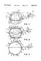
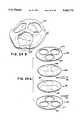
- FIG. 1is a perspective view of a polyhedral Type IA inflatable retraction device according to a first embodiment of the invention
- FIG. 2is vertical cross section, along the line 2--2 in FIG. 1, of a polyhedral Type IA inflatable retraction device according to a first embodiment of the invention
- FIG. 3is horizontal cross section, along the line 3--3 in FIG. 1, of a polyhedral Type IA inflatable retraction device according to a first embodiment of the invention
- FIG. 4Ais a longitudinal cross sectional elevational view of a body snowing a packaged collapsed Type IA retraction device according to a first embodiment of the invention ready for insertion into the abdominal cavity;
- FIG. 4Bis a longitudinal cross sectional elevational view of a body showing a packaged collapsed Type IA retraction device according to a first embodiment of the invention after it has been inserted into the abdominal cavity;
- FIG. 4Cis a longitudinal cross sectional elevational view of a body showing a Type IA retraction device according to a first embodiment of the invention during the inflation of its main chamber in the abdominal cavity;
- FIG. 4Dis a longitudinal cross sectional elevational view of a body showing a Type IA retraction device according to a first embodiment of the invention after the additional chamber has been inflated and the inflation pressure has been removed from the main chamber in the abdominal cavity;
- FIG. 5is a longitudinal cross sectional elevational view of a body showing a Type IA retraction device according to a first embodiment of the invention used to retract the bowel and lift the liver to expose the gall bladder for observation by an endoscope inserted into the main chamber of the retraction device through the main inflation tube;
- FIG. 6is a perspective view of a polyhedral Type II inflatable retraction device according to a second embodiment of the invention showing an elastomeric window attached to the inner surface of its main envelope;
- FIG. 7is a perspective view of an elastomeric window suitable for attaching to the inner surface of the main envelope of a polyhedral Type II inflatable retraction device according to a second embodiment of the invention.
- the elastomeric windowincludes an electrical element for heating temperature sensitive adhesive applied to one of the surfaces of the elastomeric window.
- FIG. 8is a perspective view of the elastomeric window of FIG. 7 packaged prior to insertion into the retraction device.
- FIG. 9is a perspective view of the outer surface of the main envelope of a polyhedral Type II inflatable retraction device according to a second embodiment of the invention.
- An elastomeric windowhas been attached to the inside of the main envelope and an aperture has been cut in the part of the main envelope covered by the elastomeric window.
- FIG. 10Ais a longitudinal cross sectional elevational view of a body showing a packaged collapsed Type II retraction device according to a second embodiment of the invention ready for insertion into the abdominal cavity;
- FIG. 10Bis a longitudinal cross sectional elevational view of a body showing a packaged collapsed Type II retraction device according to a second embodiment of the invention after it has been inserted into the abdominal cavity;
- FIG. 10Cis a longitudinal cross sectional elevational view of a body showing a Type II retraction device according to a second embodiment of the invention during the inflation of its main chamber in the abdominal cavity;
- FIG. 10Dis a longitudinal cross sectional elevational view of a body showing a Type II retraction device according to a second embodiment of the invention in its fully inflated condition in the abdominal cavity;
- FIG. 11Ais a transverse cross sectional elevational view of the abdomen showing a Type IB retraction device according to a third embodiment of the invention during the inflation of its main chamber in the abdominal cavity;
- FIG. 11Bis a transverse cross sectional elevational view of the abdomen showing a Type IB retraction device according to a third embodiment of the invention in its fully inflated condition in the abdominal cavity;
- FIG. 11Cis a perspective view of a Type IB retraction device according to a third embodiment of the invention showing an alternative form of additional cavity having tacked sidewalls.
- FIG. 12Ais a vertical cross sectional view of a polyhedral inflatable retraction device according to the invention fitted with a first embodiment of flexible sheath according to the invention installed in the abdominal cavity with the flexible sheath in its collapsed state.
- FIG. 12Bis a vertical cross sectional view of a polyhedral inflatable retraction device according to the invention fitted with a first embodiment of flexible sheath according to the invention installed in the abdominal cavity showing the flexible sheath being driven through the abdominal wall.
- FIG. 12Cis a vertical cross sectional view of a window of a polyhedral inflatable retraction device according to the invention showing a second embodiment of a flexible sheath according to the invention.
- FIG. 13Ais a perspective view of a polyhedral Type IA inflatable retraction device fitted with a suction skirt according to the invention
- FIG. 13Bis vertical cross section, along the line 2--2 in FIG. 1, of a polyhedral Type IA inflatable retraction device fitted with a suction skirt according to the invention;
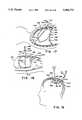
- FIG. 14Ais a longitudinal cross sectional elevational view of a body illustrating the use according to the invention of a retraction device according to the invention in the abdomen to retract the bowel to gain anterior access to the intravertebral discs, the aorta, or the kidneys for treatment or observation.
- FIG. 14Bis a transverse cross sectional elevational view of a body illustrating the use according to the invention of a retraction device according to the invention in the abdomen to retract the bowel to gain anterior access to the intravertebral discs, the aorta, or the kidneys for treatment or observation.
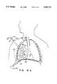
- FIG. 15is a transverse cross sectional plan view of the chest illustrating the use according to the invention of a retraction device according to the invention to retract the pericardium from the heart to gain access to the surface of the heart for treatment or observation.
- FIG. 16Ais a transverse cross sectional elevational view of the chest illustrating the use according to the invention of a retraction device according to the invention to retract the lung away from the pleura to gain access to the surface of the lung for treatment or observation.
- FIG. 16Bis a transverse cross sectional plan view of the chest illustrating the use according to the invention of a retraction device according to the invention to retract the lung away from the pleura, part of the lung entering the main chamber of the retraction device for treatment or observation.
- FIG. 17is a longitudinal cross sectional elevational view of the chest illustrating the use according to the invention of a retraction device according to the invention to retract one lobe of the lung away from the rest of the lung to gain access to occlude part of the bronchial tree during a lobectomy.
- FIG. 18is a longitudinal cross sectional elevational view of the abdomen illustrating the use according to the invention of a retraction device according to the invention to retract the liver to gain access to the gastroesophageal junction prior to sectioning the vagus nerve or to treating gastroesophageal reflux.
- FIG. 19is a longitudinal cross sectional elevational view of the head illustrating the use according to the invention of a retraction device according to the invention to retract the brain away from the dura mater to gain access to the brain for treatment or observation.
- FIG. 20Ais a transverse cross sectional elevational view of the lower abdomen illustrating the use according to the invention of a retraction device according to the invention between the abdominal wall and the peritoneum to retract the peritoneum to provide laparoscopic access to the site of a hernia without penetrating the peritoneum. A piece of mesh is shown being held in place over the site of the hernia by the retraction device,
- FIG. 20Bis a transverse cross sectional elevational view of the lower abdomen showing a retraction device according to the invention in its fully inflated condition holding a piece of mesh in position on the inside of the peritoneum over the site of the hernia.
- FIG. 21is a perspective view of a retraction device according to the invention with a piece of mesh attached to the outer surface of the main envelope.
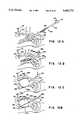
- FIG. 22Ais an exploded perspective view of the components of a polygonal Type IA retraction device illustrating the construction of such a device according to the invention.
- FIG. 22Bis a plan view of the additional envelope blank of a polygonal Type IA retraction device.
- FIG. 23Ais a perspective view of the additional envelope blank of a polygonal Type IA retraction device showing how a suction skirt according to the invention is formed from the additional envelope blank,
- FIG. 23Bis a plan view of the additional envelope blank of a polygonal Type IA retraction device showing how a suction skirt according to the invention is formed from the additional envelope blank.
- FIG. 24Ais an exploded perspective view of the components of a flat Type IA retraction device illustrating the construction of such a device according to the invention.
- FIG. 24Bis a perspective view of the assembled and inflated flat Type IA retraction device.
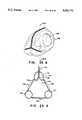
- FIG. 25Ais a perspective view of an inflated triangular prism-shaped Type IA retraction device according to the invention.
- FIG. 25Bis a vertical cross sectional view of an inflated the assembled triangular prism-shaped Type IA retraction device according to the invention along the line 25B--25B in FIG. 25A.
- FIG. 25Cis an exploded perspective view of the components of a triangular prism-shaped Type IA retraction device illustrating the construction of such a device according to the invention.
- FIG. 25Dis a plan view of the additional envelope blank of a triangular prism-shaped Type IA retraction device according to the invention.
- FIG. 26is an exploded perspective view of the components of a polygonal Type II retraction device illustrating the construction of such a device according to the invention.
- FIG. 27is an exploded perspective view of the components of a substantially hemispherical Type IA retraction device illustrating the construction of such device according to the invention.
- FIG. 28is a cross sectional view of a substantially hemispherical Type IA retraction device.
- FIGS. 1, 2, and 3show perspective, and vertical and horizontal cross sectional views, respectively, of a first embodiment 1 of a retraction device according to the invention.
- This type of retraction devicehas an additional inflatable chamber and will be designated as a Type I retraction device.
- the Type I retraction device shown in FIGS. 1, 2, and 3 with a segmented additional chamberwill be designated a Type IA retraction device.
- the retraction deviceis shown in its inflated condition.
- the retraction device 1comprises a main envelope 6 enclosing a main inflatable chamber 11.
- the main envelope 6is made of a relatively inelastic and tough film of a plastic such as Mylar®, polyethylene, or polyurethane.
- the preferred material for the main envelope 6is a polyethylene and nylon composite.
- the thickness of the main envelope 6is typically from 0.5 to 5 mils (13 to 130 microns).
- the proximal end of a main inflation tube 16is sealed into the main envelope 6.
- the main inflation tube 16allows an inflation gas to pass into and out of the main chamber 11.
- the inflation gasis typically air, nitrogen or carbon dioxide, although other suitable gases may be used.
- Typical inflation gas pressuresare in the range 0.3 to 0.7 pounds per square inch (psi) (0.21 to 0.48 kPa), the preferred pressure being 0.5 psi (0.35 kPa).
- the main inflation tube 16is provided with a port 51 on its distal end, through which endoscopes and/or surgical instruments can be passed into the main chamber 11.
- the port 51allows the inflation pressure of the main chamber 11 to be maintained when surgical instruments are passed through the port.
- the main envelope 6 of the Type IA retraction deviceis a polyhedral structure constructed from two segmented, substantially flat pieces of plastic film, which gives the retraction device a substantially polyhedral shape.
- two non-segmented, substantially flat pieces of plastic filmcan be used to make a relatively flat Type IA retraction device.
- the retraction devicecan be constructed from curved pieces of plastic film, which gives the retraction device a substantially spherical, spheroidal, or ellipsoidal shape.
- the size of retraction devices according to the inventioncan range from about 2" (50 mm) wide by about 0.5" (12 mm) high, for use inside the pericardium, to 10"-14" (250-350 mm) wide by 4"-8" (100-200 mm) high, for use in the abdominal cavity.
- the size of retraction device required for a given applicationdepends on the application and the size of the patient.
- the additional envelope 21is made from a film of the same thickness of the same plastic as the main envelope 6.
- the additional envelope 21may be advantageous make from a film of a different thickness of the same plastic, or the same or a different thickness of a different plastic.
- the periphery 26 of the additional envelope 21is attached to the surface of the main envelope 6.
- the additional envelope 21has a segmented shape such that, when its periphery 26 is attached to the main envelope 6, and the additional chamber 31 formed between the outside of the main envelope 6 and the inside of the additional envelope 21 is inflated, the additional chamber 31 forms a cage structure inside or outside the main chamber 11, as shown in the figures.
- the cage structureis preferably formed on the faces of the polyhedron.
- the parts of the main envelope 6 that do not form part of the wall of the additional chamber 31provide a plurality of windows 46 that can be punctured to provide access for surgical instruments into and out of the main chamber 11.
- the additional envelope 21is attached, preferably to the outer surface of the main envelope 6, by welding along the periphery 26 of the additional envelope; alternatively, an adhesive may be applied to the periphery 26 of the additional envelope 21, and the additional envelope 21 brought into contact with the main envelope 6.
- Other methods that produce a flexible, gas-tight seal between the periphery 26 of the additional envelope 21 and the main envelope 6may also be used.
- the additional inflation tube 41allows an inflation gas to pass into and out of the additional chamber 31.
- the inflation gasis typically air, nitrogen or carbon dioxide, although other suitable gases may be used. Typical inflation gas pressures are in the range 4 to 6 psi (2.8 to 4.1 kPa), the preferred pressure being 5 psi (3.5 kPa).
- the inflation gas pressure in the additional chamberis considerably higher than that in the main chamber to enable the additional chamber to exert sufficient force to keep already retracted organs in their retracted state despite the much smaller surface area of the additional chamber.
- the main inflation tube 16is sealed through the additional envelope 21.
- the main inflation tube 16 and the additional inflation tube 41are contained within an inflation tube shield 61, which forms a gas-tight seal with the retraction device.
- the outer wall of the inflation tube shield 61forms a gas-tight seal with the trocar or sheath through which it passes into the body cavity.
- the inflation tube shield 61can be a separate component.
- an extrusioncan provide the inflation tube shield 61, the main inflation tube 16 and the additional inflation tube 41 in a unitary structure.
- the basic embodiment of a Type I retraction devicehas a single additional chamber 31.
- additional chamber 31is divided into a plurality of sub-chambers (not shown).
- the sub-cheersare isolated from one another, so that if one or more of them is accidentally punctured while the retraction device is in use, deflation of all of the retraction device can be avoided.
- Each sub-chambercan be equipped with its own additional inflation tube.
- each sub-chambercan be connected to an inflation manifold (not shown) through a non-return valve (not shown). This arrangement requires that each sub-chamber be deliberately punctured to deflate the retraction device in preparation for withdrawing the retraction device from the body at the end of the treatment procedure.
- the additional envelope 21may be attached to the inner surface of the main envelope 6.
- the main inflation tube 16passes through the additional chamber and forms a gas-tight seal with the additional envelope 21 in addition to the main envelope 6.
- the additional envelope 21need not be segmented.
- the additional chamber 31is formed by attaching the additional envelope 21 to the main envelope 6, the line of attachment forming the periphery of the cage structure of the additional chamber 31.
- each window 46comprises a double thickness of film. This makes it somewhat more difficult to cut an aperture in a window.
- neither the main envelope 6 nor the additional envelope 21are segmented.
- the additional envelope 21has a number of holes cut in it.
- the additional cheer 31is formed by attaching the periphery of each hole in the additional envelope 21 to the main envelope 6.
- FIGS. 25A, 25B, 25C, and 25Dshow a Type IA retraction device in the shape of a triangular prism particularly suitable for use in the upper abdomen.
- the main envelope 6 and the additional envelope 21are serrated rectangles, as shown in FIGS. 25C and 25D.
- the additional envelopehas three large holes cut in it.
- the additional chamber 31is formed by attaching the periphery of each hole in the additional envelope 21 to the main envelope 6. Opposite ends of the long axis of the rectangle and the serrations are joined together to form the triangular structure.
- All embodiments of the Type IA retraction devicemay be provided with tabs 56 on the inside the main envelope in accordance with a further aspect of the invention, as shown in FIGS. 2 and 3.
- the tabs 56may be separate components attached to the inside of the main envelope 6 by welding, an adhesive, or some other suitable method.
- the tabs 56can be an integral part of the main envelope 6 suitably extended into the main chamber 11.
- Tabs 56provide points inside the main chamber 11 that can be gripped by a suitable gripping tool (not shown) inserted into main chamber 11 through the main inflation tube 16.
- the gripping toolallows the inflated retraction device to be manipulated to change its position so that, for instance, one of its windows can be aligned with the organ or tissue to be treated or observed. Partially deflating the inflated retraction device makes repositioning easier.
- the word “organ”will be used to mean an organ or a tissue that is retracted by the retraction device.
- the word “treat”will be used to mean both treat and observe, and the word “treatment” will be used to mean both treatment and observation.
- the word “tissue” or the phrase “tissue to be treated”will both be used to mean the organ or the tissue that is treated through or inside the retraction device.
- FIGS. 4A through 4Dshow a cross sectional elevational view of the abdomen A to illustrate the method by which a Type IA retraction device according to the invention is inserted into the body and used to retract an organ within the body to gain access to treat a tissue.
- the retraction deviceis inserted into the abdomen A and is used to retract an organ, the bowel B, to gain access to treat a tissue, the gall bladder GB. Similar methods are used to insert a retraction device according to the invention into other parts of the body.
- Inflatable retraction device 1is supplied in a collapsed state, as shown in FIG. 4A, in which it is tightly packaged in a configuration that makes it essentially a linear extension of the inflation tube shield 61.
- the retraction device 1is packed so that when pressure is applied to the main inflation tube 16, the retraction device 1 deploys without tangling.
- the packaged retraction devicewill fit through an insertion tube (usually a trocar tube) of between 3 and 20 mm (0.12"-0.8") in diameter, a typical diameter being 14 mm (0.55").
- the retraction device 1is retained in its collapsed state by the sleeve 100 which, in turn, is held together by one-pull lacing 105.
- the sleeve 100can be fitted with a tear-off strip (not shown). Pulling on the thread 125 detaches the one-pull lacing 105 or the tear-off strip from the sleeve 100, releasing the collapsed retraction device 1.
- the sleeve 100can be provided with suitable markings 115 to enable its orientation to be determined and, if necessary, adjusted, after insertion into the body and before inflation.
- the abdomen APrior to starting the procedure, the abdomen A may be lifted to provide additional working space by gas insufflation, or by one of the mechanical devices disclosed in U.S. patent application Ser. No. 706,781, of which application this application is a Continuation-in-Part.
- the insufflated condition of the abdomen Ais indicated by the broken line A'.
- a small incisionis made in the skin of the abdomen A and a trocar (not shown) and trocar tube 120 are inserted into the incision and are driven through the wall of the abdomen A.
- the trocaris withdrawn.
- a second small incisionis made in the skin of the abdomen A and a trocar (not shown) and trocar tube 122 are inserted into the incision and driven through the wall of the abdomen.
- the trocaris withdrawn and an endoscope 110 is inserted into the trocar tube 122.
- the second incisionis located so that the endoscope 110 can observe the intended placement site of the retraction device 1.
- a small endoscope(not shown), preferably about 2 mm (0.1") in diameter, may be attached to the collapsed retraction device so that the location of the retraction device inside the abdomen may be determined.
- the endoscope 110is not used, and the second incision need not be made.
- the collapsed retraction device 1is threaded, with the aid of its inflation tube shield 61, through the trocar tube 120 into the abdominal cavity AC, as shown in FIG. 4B, and manipulated into its correct position.
- the position of collapsed retraction device 1 in the abdominal cavity ACis observed through the endoscope 110: the markings 115 enable the orientation of retraction device 1 to be determined and adjusted if necessary.
- the position of the collapsed retraction deviceis determined by means of the small endoscope (not shown) attached to the retraction device.
- the thread 125is then pulled to release the sleeve 100 from around collapsed retraction device 1, and the sleeve 101 is withdrawn from the abdominal cavity AC through the trocar tube 120 by means of the thread 125.
- the main inflation tube 16is connected to a source of inflation gas (not shown) and the gas supply is slowly turned on to inflate the main chamber 11.
- the retraction device 1slowly expands, as shown in FIG. 4C, progressively displacing the bowel B as its size increases.
- the retraction device 1presents a relatively large surface area to the bowel B, and thus displaces the bowel B gently, progressively, and without trauma.
- the main chamber of the retraction deviceis capable of exerting the force necessary to effect the displacement the bowel B.
- the retraction device 1Once the retraction device 1 has reached its fully-inflated condition, its position is checked by viewing it through the endoscope 110 and/or an endoscope (not shown) inserted into its main chamber 11 via the main inflation tube 16 and the port 51. The tissue to be treated must be covered by one of the windows 46 of retraction device 1.
- the inflation gas pressureis reduced slightly to partially deflate retraction device 1.
- a suitable gripping toolis passed through the port 51 and the main inflation tube 16 into the interior of the retraction device 1, to grip one of the tabs 56 (FIGS. 2 and 3).
- the gripping toolis manipulated to correct the positioning error while the position of the retraction device 1 is observed through the endoscope 110 or the endoscope (not shown) in the main chamber 11. Once the error is corrected, the main chamber 11 of the retraction device 1 is reinflated by means of the main inflation tube 16.
- the additional inflation tube 41is connected to a source of inflation gas (not shown) and the additional chamber 31 is inflated to the required pressure, as shown in FIG. 4D.
- the source of inflation pressurecan be removed from the main chamber 11 and the main inflation tube 16.
- the port 51can be removed from the main inflation tube 16 since a gas-tight seal is no longer required around instruments inserted into the main inflation tube 16, the main chamber 11 now being at atmospheric pressure.
- a cutting instrument 52is then passed through the main inflation tube 16 into the main chamber 11 to cut a suitable aperture 54 in the window 46 that covers of the tissue to be treated, as shown in FIG. 5.
- an additional puncturemay be made in the abdominal wall and a cutting instrument 62 passed through this puncture to cut an aperture 54A in a window 58 to gain access to the main cavity 11, and thence to cut a suitable aperture 54 in the window 46.
- the aperture 54provides an access to the tissue to be treated; for example, the gall bladder GB.
- the aperture 54may simply be a cut in the window 46, or all or part of the window 46 may be removed to provide the aperture 54.
- an alternative way of passing instruments into the main chamber 11is to make at least one further incision in the body wall, the further incision being made in a location adjacent a further window 58 of the retraction device, as shown in FIG. 5.
- a trocar (not shown) with tube 60is inserted into the further incision and is driven through the body wall to pierce the further window 58. The trocar is withdrawn leaving the trocar tube 60 in place. Instruments, e.g., instrument 62 are then inserted into the retraction device as required through the trocar tube 60 and the further window 58.
- FIG. 5additionally shows the retraction device 1 in place in the abdominal cavity AC in its fully inflated form.
- the main chamber 11is not pressurized; the shape of the retraction device is maintained by the inflated additional chamber 31.
- retraction device 1was placed before inflation such that when the main chamber 11 was inflated, the expansion of the retraction device 1 displaced the bowel B to the right of the drawing and lifted the liver L upwards to expose the tissue to be treated, i.e., the gall bladder GB.
- the additional chamber 31is disconnected from the source of inflation pressure and the pressure in the additional chamber 31 is released to collapse the retraction device. Collapsing the retraction device is assisted by connecting the additional inflation tube 41 to a vacuum line (not shown) to evacuate the additional chamber 31. Once the retraction device 1 is fully collapsed, the trocar tube 120 is withdrawn from the abdominal cavity, the retraction device 1 is withdrawn through the small abdominal opening, and the openings in the abdominal wall are closed in the normal way.
- FIG. 6shows an alternative embodiment 201 of a retraction device that maintains its shape while allowing treatment to be carried out working through or inside it.
- the alternative embodimentlacks the second inflatable chamber of the Type I embodiment shown in FIGS. 1 through 5, and has only a main envelope 206 enclosing a main chamber 211.
- the single chamber embodiment of the retraction devicewill be designated as a Type II retraction device.
- the main chamber 211remains inflated throughout the treatment process, access to the tissue to be treated being provided by an elastomeric window 261 attached to the main envelope 206.
- the elastomeric window 261is self-sealing and maintains inflation pressure in the main chamber 211 by forming a substantially gas-tight seal around instruments passed through it.
- the elastomeric window 261also forms a substantially gas-tight seal around the tissue to be treated if the tissue to be treated is pulled through the elastomeric window 261 into the main chamber 211 for treatment.
- the main envelope 206is made of a relatively inelastic and tough film of a plastic such as Mylar®, polyethylene, or polyurethane.
- the preferred material for the main envelopeis a polyethylene and nylon composite.
- the thickness of the main envelope 206is typically from 0.5 to 5 mils (13 to 130 microns).
- the proximal end of a main inflation tube 216is sealed into the main envelope 206.
- the main inflation tube 216allows an inflation gas to pass into and out of the main chamber 211.
- the inflation gasis typically air, nitrogen or carbon dioxide, although other suitable gases may be used. Typical inflation gas pressures are in the range 0.3 to 0.7 psi (0.21 to 0.48 Pa), the preferred pressure being 0.5 psi (0.35 kPa).
- the main inflation tube 216is provided with a port 251 on its distal end, through which endoscopes and other surgical instruments can be passed into the main chamber 211.
- the port 251provides a gas-tight seal around instruments passed through it and allows inflation pressure to be maintained in the main chamber 211 with instruments present.
- the main envelope 206 of the Type II retraction device shown in FIG. 6is a polyhedral structure constructed from two segmented, substantially flat pieces of plastic film, which gives the retraction device a substantially polyhedral shape.
- two non-segmented substantially flat pieces of plastic filmcan be used to make a relatively flat Type II retraction device.
- the retraction devicecan be constructed from curved pieces of plastic film, which gives the retraction device a substantially spherical or spheroidal shape.
- Type II retraction devicescan range from about 2" (50 mm) wide by about 0.5" (12 mm) high, for instance for use inside the pericardium, to 10"-14" (250-350 mm) wide by 4"-8" (100-200 mm) high, for use in the abdominal cavity.
- the size of retraction device required for a given applicationdepends on the application and the size of the patient.
- the lack of a additional chamber in the retraction device 201 shown in FIG. 6makes orientation less critical. If the main envelope 206 is constructed from one or two curved pieces of film, orientation is particularly uncritical. If the main envelope 206 is a polyhedral structure having a number of faces, some orientation is required because the tissue to be treated must be substantially centered on one of the faces.
- the retraction device 201can be provided with tabs 256 on the inside the main envelope 206. Tabs 256 may be separate components attached to the inside of the main envelope 206 by welding, an adhesive, or some other suitable method. Alternatively, tabs 256 can be an integral part of the main envelope 206 suitably extended into the main chamber 211.
- Tabs 256provide points on the inside of the main chamber 211 that can be gripped by a suitable gripping tool (not shown) inserted into main chamber 211 through the inflation tube 216 and port 251.
- the gripping toolallows the inflated retraction device 201 to be manipulated to change its position so that the desired point on the tissue to be treated can be substantially centered on one of its faces. Partially deflating the inflated retraction device makes repositioning easier.
- the elastomeric window 261is installed on the inside of the main envelope 206 after the retraction device 201 has been placed in the body and inflated.
- the elastomeric window 261is shown in FIG. 7 and comprises a flat piece 266 of a film of an elastomeric material such as latex or silicone rubber about 0.5" to 1.5" (12 to 37 mm) in diameter.
- the periphery of the elastomeric film 266is attached by means of a suitable adhesive, such as an acrylic cement or a silicone adhesive to one of the flat faces of a ring 271 having a square or rectangular cross section.
- the ring 271is circular or elliptical in shape and is of a springy material such as polyethylene or stainless steel, so that will regain its circular or elliptical shape after being compressed across one of its diameters to enable it to be passed through the inflation tube 216.
- the other flat face 276 of the ring 271is coated with an adhesive.
- a pressure-sensitive adhesivesuch as a contact rubber adhesive may be used.
- a hot-melt adhesive of the type used in woodworking glue gunsis used. If a hot-melt adhesive is used, a heating element 281, made of a suitable resistance wire, such as Nichrome, is inserted into a narrow groove in the face 276 of the ring 271 to which the adhesive is applied. Suitable electrical leads 291 are connected to the heating element 281.
- the elastomeric windowBefore it can be inserted into the retraction device 201, the elastomeric window must be wrapped across one of its diameters to reduce its width so that it can pass through the main inflation tube 216, as shown in FIG. 8.
- a one-pull lacing arrangement 205, or a sleeve with a tear strip (not shown)can be used. Wrapped elastomeric window 261 is attached to a manipulation rod 286 for insertion into the retraction device. Also attached to the manipulation rod is the thread 225 to release the one-pull lacing 205 or the tear strip (not shown) and, if a temperature-sensitive adhesive is used, the electrical leads 291 for the heating element 281 (FIG. 7).
- the wrapped elastomeric window 261 on the end of the manipulating rod 286is passed through the port 251 and the main inflation tube 216 into the main chamber 211.
- the lacing 205 or tear-stripis released, which allows the elastomeric window 261 to resume its circular shape.
- the elastomeric window 261is then manipulated to bring it into contact with the main envelope 206 such that the elastomeric window 261 covers the tissue to be treated. If a pressure-sensitive adhesive is used, the face 276 of the elastomeric window is pushed against the main envelope 206 to affix the elastomeric window 261 in place.
- the face 276 of the elastomeric windowis placed against the main envelope 206 and a suitable source of electric current (not shown) is applied to the electrical leads 291 for the time required to melt the adhesive and affix the elastomeric window 261 to the main envelope 206.
- the manipulating rod 286is detached from it and withdrawn from the main chamber 211.
- a suitable cutting instrument 252is passed through the port 251 and the main inflation tube 216 into the main chamber 211 and through the elastomeric window 261, as shown in FIG. 6.
- the elastomeric window 261forms a gas-tight seal around the cutting instrument 252, and re-seals itself after the cutting instrument 252 is withdrawn.
- the cutting instrument 252is used to cut an aperture in the part 296 of the main envelope 206 that is covered by the elastomeric window 261.
- the part 296 of the main envelope 206is shown by shading in FIG. 9.
- the aperture 254may simply be a cut in the part 296 of the envelope 206, or all or part of the part 296 of the envelope 206 may be removed to provide the aperture 254.
- Procedures that are carried out using instruments passed through the elastomeric window 261require removing more of the part 296 of the envelope 206 than procedures in which the tissue to be treated enters the retraction device through the aperture 254 and the elastomeric window 261.
- the elastomeric window 261forms a seal around the tissue and isolates it from the body outside the retraction device.
- the treatment procedureis then carried out by inserting instruments through the port 251 and the main inflation tube 216 into the main chamber 211 and either working through the elastomeric window 261 or working on the tissue to be treated inside the cavity 211.
- the retraction device 201is inserted into the abdomen using a procedure similar to that used to insert a Type IA retraction device.
- Inflatable retraction device 201is supplied in a collapsed state, as shown in FIG. 10A, in which it is tightly packaged in a configuration that makes it essentially a linear extension of the main inflation tube 216.
- the retraction device 201is packed so that when inflation pressure is applied to the main inflation tube 216, retraction device 201 deploys without tangling.
- the packaged retraction devicewill fit through an insertion tube of between 3 and 20 mm (0.12"-0.8") in diameter, a typical diameter being 14 mm (0.55").
- the retraction device 201is retained in its collapsed state by a sleeve 100 which, in turn, is held together by one-pull lacing 105 or a tear strip (not shown).
- the sleeve 100can be provided with suitable markings 115 to enable its orientation to be determined and, if necessary, adjusted, after insertion into the abdomen and before inflation.
- the abdomen APrior to inserting the retraction device, the abdomen A may be lifted to provide additional working space by gas insufflation, or by one of the mechanical devices disclosed in U.S. patent application Ser. No. 706,781, of which application this application is a Continuation-in-Part.
- the insufflated state of the abdomen Ais indicated by the broken line A'.
- a small incisionis made in the skin of the abdomen A and a trocar (not shown) and trocar tube 120 are inserted into the incision and are driven through the wall of the abdomen A.
- the trocaris withdrawn.
- a second small incisionis made in the skin of the abdomen A and a trocar (not shown) and trocar tube 122 are inserted into the incision and driven through the wall of the abdomen.
- the trocaris withdrawn and an endoscope 110 is inserted into the trocar tube 122.
- the second incisionis located so that the endoscope 110 can observe the intended placement site of the retraction device 1.
- a small endoscope(not shown), preferably about 2 mm (0.1") in diameter, may be attached to the collapsed retraction device so that the location of the retraction device inside the abdomen may be determined.
- the endoscope 110is not used, and the second incision need not be made.
- the collapsed retraction device 201is threaded, with the aid of its main inflation tube 216, through the trocar tube 120 into the abdomen A, and manipulated into its correct position.
- the position of collapsed retraction device 201is observed through the endoscope 110: the markings 115 enable the orientation of the retraction device to be determined and adjusted if necessary.
- the position of the collapsed retraction deviceis determined by means of the small endoscope (not shown) attached to the retraction device.
- the thread 125is then pulled to release the sleeve 100 from around the collapsed retraction device 201, as shown in FIG. 10B, and the sleeve 100 is withdrawn from the abdominal cavity AC through the trocar tube 120 by means of the thread 125.
- the main inflation tube 216is connected to a source of inflation gas (not shown).
- the inflation gas pressureis slowly increased to inflate the main chamber 211.
- the retraction device 201slowly expands, progressively displacing the bowel B as its size increases, as shown in FIG. 10C. Throughout the expansion process, the retraction device 201 presents a relatively large surface area to the bowel B, and thus displaces the bowel gently, progressively, and without trauma. Although the retraction device 201 retracts the bowel B gently, the main chamber of the retraction device 201 is capable of exerting the force necessary to effect the displacement of the bowel.
- retraction device 201Once retraction device 201 has reached its fully-inflated condition, its position is checked by viewing it through either the endoscope 110 and/or an endoscope (not shown) inserted into the main chamber 211 of the retraction device 201 via the port 251 and the main inflation tube 216.
- the tissue to be treatedshould be in contact with the main envelope 206 and lie substantially directly in line with the main inflation tube 216. Further, if the retraction device is a polyhedron, the tissue to be treated should be substantially centered in one of its faces.
- the position of the retraction device 201can be adjusted by gripping one or more of the tabs 256 with a suitable gripping tool (not shown), as described above.
- FIG. 10Dshows the retraction device 201 in its fully inflated state with the elastomeric window 261 installed, and the instrument 252 passed through the elastomeric window 261 and the aperture 254 in the main envelope 206 to treat the tissue to be treated, the gall bladder, GB.
- the main chamber 211is disconnected from the source of inflation pressure and the pressure in the main chamber 211 is released to collapse the retraction device. Collapsing the retraction device is assisted by connecting the main inflation tube 216 to a vacuum line (not shown) to evacuate the main chamber 211. Once fully collapsed, the retraction device 201 is withdrawn from the abdominal cavity through the opening in the abdominal wall that remains after withdrawing the trocar tube 120. The elastomeric window 261 is sufficiently flexible to be withdrawn through the opening in the abdominal wall along with the retraction device 201. The openings in the abdominal wall are then closed in the normal way.
- FIGS. 11A, 11B, and 11CA further embodiment of the invention, which is a variation on the Type I retraction device, designated Type IB, is shown in FIGS. 11A, 11B, and 11C.
- This variationhas the advantage of providing two large, flat windows, but has the disadvantage that it does not allow any access to tissues lying to the side of the retraction device.
- the retraction device 301 shown in FIGS. 11A and 11Bis substantially cylindrical in shape.
- a stack of one or more toroidal chambersforms the additional chamber 331.
- the example shown in FIGS. 11A and 11Bhas 3 toroidal chambers 325, 327 and 329.
- a single chamber having sidewalls 333 that are tacked togethercan be used for the additional chamber 331.
- the tacked sidewallsform an enclosure having a height that is considerably greater than its width.
- the diaphragms 307 and 309cover the top and bottom, respectively, of the retraction device 301.
- the main inflation tube 316is sealed into the main chamber 311 and allows the main chamber to be inflated.
- the additional inflation tube 341is sealed into the additional chamber 331. If more than one toroidal chamber is used to provide the additional chamber, the toroidal chambers may be interconnected and a single additional inflation tube 341 used, or each toroidal chamber may be provided with its own additional inflation tube (not shown). The latter approach prevents the retraction device 301 from collapsing completely if one of the toroidal chambers 325, 327, or 329 is accidentally punctured, and also allows the height of the retraction device to be adjusted by selectively inflating the toroidal chambers 325, 327, or 329.
- the Type IB retraction device shown in FIGS. 12 and 13is constructed from similar materials to the Type IA retraction device, and may be fitted with tabs 356, similar to tabs 56 in the Type IA retraction device, to enable it to be properly positioned after inflation.
- a similar procedureis used to deploy the Type IB retraction device in the body as is used to deploy the Type IA retraction device, and will not be described in detail.
- a similar inflation procedureis used, except that the additional chamber may be inflated at least partially at the same time as the first cavity is inflated.
- the Type IB retraction devicedepends more for its shape on the additional chamber than the Type IA retraction device. Hence, at least partial inflation of the additional chamber is necessary to enable the retraction device to displace organs to the side of the retraction device. Inflation pressures similar to those used for the Type IA retraction device are used.
- Treatment procedures using the Type IB retraction deviceare similar to those using the Type IA retraction device, except that the Type IB retraction device does not provide access to tissues to the side of the device.
- the diaphragms 307 and 309are analogous to the windows 46 (FIG. 1) of the Type IA retraction device. Either or both of the windows provided by the diaphragms 307 and 309 may be pierced to provide apertures though which treatment may be carried out, or through which the tissue to be treated may be brought into the retraction device for treatment, or through which instruments may be passed into and out of the main chamber 311.
- a further aspect of the inventionis the provision in a retraction device according to the invention, of one or more flexible sheaths to interconnect the main chamber of the retraction device and the outside of the body into which the retraction device is inserted.
- the flexible sheathprovides a tract through the body wall that allows additional surgical instruments or endoscopes to be introduced into the main chamber of the retraction device, and/or allows tissue and the like to be removed.
- the flexible sheathis attached to a window of a Type I retraction device or to the main envelope of a Type II retraction device.
- FIG. 12Ashows a flexible sheath according to the invention attached to a window 46 of a Type IA retraction device 1, which is shown as an example.
- a flexible sheath according to this aspect of the inventioncan also be used with Type IB and Type II retraction devices.
- the flexible sheath 3is substantially cylindrical in shape with a closed distal end 8.
- the proximal end 13 of the flexible sheathis attached to the outer surface of the window 46.
- the sidewall 18 of the flexible sheath 3is folded concertina-style when the retraction device is packaged, and remains folded after the retraction device has been inflated.
- a suitable pointed tool 23is fed into the main chamber 11 to pierce a hole 28 in the part of the window 46 that is covered by the flexible sheath 3.
- the pointed tool 23is pushed through the hole 28 to engage with the distal end 8 of the flexible sheath 3.
- the distal end 8is first pressed against the inner surface of the body wall W using the pointed tool 23.
- the resulting bulge in the skin S on the outside of the bodyindicates where the flexible sheath 3 will emerge.
- a small incision 33is made in the skin S at that point.
- the flexible sheath 3is then driven by the pointed tool 23 through the body wall W to emerge through the incision 33.
- the distal end 8 of the flexible sheath 3is then opened to provide access to the main chamber 11.
- the flexible sheathdoes not have to be gas-tight in the manner of conventional trocar sheaths, and permits ordinary surgical instruments to be used.
- the flexible sheathis fitted with a gas-tight port similar to the port 251 (FIG. 6) before the distal end 8 is opened.
- FIG. 12CThe alternative embodiment of a flexible sheath 43 according to the invention, shown in FIG. 12C, is not initially attached to the retraction device.
- a Type IA retraction device 1is shown in FIG. 12C as an example.
- a flexible sheath according to this aspect of the inventioncan also be used with Type IB and Type II retraction devices.
- the flexible sheath 43comprises a cylindrical piece of flexible plastic 48 with a coaxial locking device 53 on its proximal end.
- the distal end of the flexible sheath for a Type II retraction devicemust be closed by a port (not shown) similar to the port 251 (FIG. 6) so that pressurization of the main cavity can be maintained after the flexible sheath 43 has been installed.
- the flexible sheath 43is installed after the retraction device 1 has been deployed in the body. A small incision 58 is made in the skin S of the body. The flexible sheath 43 is then driven through the body wall W by a sharp trocar point (not shown). The trocar point pierces a hole 63 in the window 46 of the retraction device 1, and pushes the locking device 53 of the flexible sheath 43 through the hole 63 to engage the locking device 53 with the window 46. When used with a Type II retraction device, the locking device 53 forms a gas-tight seal with the window 46.
- a retraction device according to the inventionmay be fitted with a tubular suction skirt on the part of the retraction device that is lower-most when the retraction device is deployed in the body.
- FIGS. 13A and 13Bshow, as an example, a polygonal Type IA retraction device of the type used in the abdominal cavity.
- the suction skirt of this aspect of the inventioncan be used with other type I and type II retraction devices.
- suction skirt 12 on the bottom of the retraction deviceis connected to a suction line and removes such fluid during the treatment procedure, keeping the cavity clear of accumulated fluids.
- the suction skirtis a tubular appendage attached to the lower-most extremity of the retraction device.
- the suction skirtis formed from part of the additional envelope 21 around the bottom window 46.
- the bottom or sides of the suction skirtis pierced with between six and twelve holes 17. In the embodiment shown, the suction skirt is about 1/4" (6.2 mm) in diameter, and the holes 17 are about 1/8" (3.1 mm) in diameter.
- the suction skirtis made of the polyethylene-nylon composite that is the preferred material for the main envelope 6 of the retraction device. This material is sufficiently resilient that a tubular structure made from it can retain its open cross section under a low vacuum.
- One end of the suction skirtis closed; the other is connected to a thin-wall polyethylene tube 22 that runs up the side of the retraction device to exit the body through the same incision as is used for the inflation tubes. If, as is shown in FIGS. 13A and 13B, the retraction device is used in an insufflated body cavity, the suction skirt tube 22 passes inside the inflation tube sheath 61.
- the distal end of the suction skirt tube 22has attached to it a connector suitable for attaching to an operating room suction line.
- FIG. 14The method according to the invention of using a retraction device according to the invention in a procedure to perform an anterior resection of a herniated intervertebral disc is illustrated in FIG. 14.
- a methodcan be adapted to gain anterior access to the aorta, the kidneys, and other tissues that lie outside the peritoneum.
- FIG. 14Ashows a longitudinal cross section of the body; and
- FIG. 14Bshows a transverse cross section along the line 14B--14B in FIG. 14A.
- Anterior access to the spineis normally difficult due to the difficulty of retracting the overlying bowel using conventional laparoscopic retractors.
- a Type I or a Type II retraction deviceis used according to the invention to retract the bowel by forming a small incision 420 in the abdominal wall W and inserting a trocar (not shown) with trocar tube 430 into the incision 420 and driving the trocar into the abdominal cavity AC.
- the trocaris removed and the retraction device 401 is passed through the trocar tube 430 into the abdominal cavity AC in its contracted state with the aid of its inflation tube or inflation tube shield (the inflation tube shield 461 of a Type IA retraction device is shown).
- the main chamber 411 of the retraction device 401is inflated with a suitable inflation gas passed though inflation tube 416.
- the relatively large surface area of the main chamber 411 of the retraction devicegently retracts the bowel 431, either upwards or downwards, depending on the position of the disc to be treated.
- the positioning of the retraction deviceis checked and adjusted, if necessary, as previously described.
- a Type I retraction deviceIf a Type I retraction device is used, it must be positioned such that the disc that it is desired to treat is centered in one of its windows.
- the additional chamber 431is inflated, and the inflation gas pressure in the 411 main chamber is released.
- the inflated additional chambermaintains the shape of the retraction device.
- an elastomeric window(not shown) is installed, as previously described, on the inside of the main envelope in a position that will provide access to the disc to be treated.
- the main envelope 406 of both types of retraction devicecan then be pierced, and partially removed, if necessary. An incision is made in the peritoneum exposed by the retraction device to gain access to and to resect the disc to be treated.
- FIGS. 14A and 14Bshow instrument 452 passed from outside the body through the main inflation tube 416 into the main chamber 411. The instrument 452 passes out of the main chamber 411 through an aperture (not shown) pierced in the window 446.
- the retraction deviceis deflated and removed from the body, and the small incisions in the abdominal wall repaired, as already described.
- FIG. 15shows a transverse cross section of the chest. Displacement of the pericardium allows the outer surface 413 of the heart 408 to be observed, and such procedures as endocardial mapping, ablation, transmyocardial revascularization, and defibrillation to be carried out. These procedures have until now been difficult to do laparoscopically because access to the surface of the heart 408 is obstructed by the pericardium 403.
- a small puncture 418is made in the chest wall 423 and through the puncture 418, a small incision 428 is made in the pericardium 403.
- An introducer tube(not shown) is inserted to connect the pericardial cavity 453 to outside the patient.
- a retraction device 401 according to the inventionis inserted using its inflation tubes (the main inflation tube 416 is shown) through the introducer tube into the pericardial cavity 453 so that it rests between the surface 413 of the heart and the pericardium 403.
- the retraction device 401is then released from its packing (not shown), as described above, and its main chamber 411 is inflated.
- the main envelope 406 of the retraction devicegently displaces the heart 408 from the pericardium 403.
- the position of the retraction deviceis checked and, if necessary, adjusted.
- Type I retraction deviceIf a Type I retraction device is used, it must be positioned such that the part of the heart that it is desired to treat is centered in one of its windows. The additional chamber 431 is then inflated and the inflation pressure removed from the main chamber.
- an elastomeric windowis installed, as previously described, on the inside of the main envelope in a position that will provide access to the part of the heart to be treated.
- the introducer tube(not shown) can be withdrawn and the main inflation tube 416 used as a path for endoscopes and instruments to pass in to the main chamber of the retraction device.
- FIG. 15shows an endoscope 433 passed through the main inflation tube 416 to observe the outer surface 413 of the heart.
- FIG. 15also shows an instrument probe 438 that has been passed through the chest wall 423 to contact the surface 413 of the heart.
- the instrument probe 438is passed through the pericardium 403 and the main chamber 411 of the retraction device 401, piercing a first window 443 and a second window 448 of the retraction device.
- the retraction deviceis withdrawn from the pericardial cavity, as already described, and the small incisions in the pericardium and the chest wall are repaired.
- FIG. 16shows a further procedure according to the invention in which a retraction device according to the invention is used in the pleural cavity to retract the lung from the pleura to allow observation and manipulation.
- FIG. 16Ashows a vertical cross sectional view of the chest and
- FIG. 16Bshows a transverse cross section along the line 16B--16B in FIG. 16A.
- a small, oblate version of a Type I or Type II retraction device 401 according to the inventionis used to displace the lung 402 from the pleura 407 to allow resection of a lobe 412 of the lung 402.
- a small incision 417is made in the chest wall 423 and, through the incision 417, a trocar (not shown) is inserted to connect the pleural cavity 432 to outside the patient.
- the trocar point (not shown)is removed leaving the trocar tube (not shown) connecting the pleural cavity 432 to outside the patient.
- a retraction device 401 according to the inventionis inserted using its inflation tubes (inflation tube 416 is shown) through the trocar tube into the pleural cavity, so that it rests between the surface of the lung 402 and the pleura 407.
- the retraction device 401is then released from its packing (not shown), as described above, and its main chamber 411 is inflated.
- the main envelope 406 of the retraction devicegently displaces the lung 402 from the pleura 407.
- the position of the retraction deviceis checked and, if necessary, adjusted.
- a Type I retraction deviceIf a Type I retraction device is used, it must be positioned such that the part of the lung that it is desired to treat is centered in one of its windows. The additional chamber 431 is then inflated and the inflation pressure removed from the main chamber 411.
- an elastomeric windowis installed, as previously described, on the inside of the main envelope in a position that will provide access to the part of the lung to be treated.
- the trocar tube(not shown) can be withdrawn and the main inflation tube 416 used as a path for endoscopes and instruments to pass to the inside of the retraction device.
- FIG. 16shows an endoscope 433 passed through the main inflation tube 416 into the main chamber of the retraction device 401.
- the main inflation tube 416enters the main chamber 411 through a first window 443. Paint of a second window 448 has been removed, as already described, to allow a part 437 of the lung 402 to enter the main chamber 411 of retraction device for treatment.
- a trocar tube 447passes through the chest wall 423 and enters the retraction device by piercing a third window 452, and an instrument 442 is passed through the trocar tube 447 to section part of the lung 437.
- the part of the window 448 that has not been removedforms a seal around the part 437 of the lung inside the retraction device, and prevents sectioned tissue from entering the pleural cavity.
- the retraction deviceis withdrawn from the pleural cavity, as already described, and the small incisions in the pleura and the chest wall are repaired.
- a retraction deviceis used to retract one lobe of a lung in a lobectomy. This is shown in FIG. 17, which shows a longitudinal cross section of the chest.
- the lobes of the lungoverlay one another: in performing a lobectomy, access to the hilar portion of the bronchial tree is required so that the branches of the bronchial tree feeding the lobe to be sectioned can be occluded.
- a Type IA or Type II retraction device 401 according to the inventionis used to displace the lobe 404 away from the rest of the lung 409 to provide access to the bronchial tree 414.
- a small incision 419is made in the chest wall 423, and through the incision 419, a trocar (not shown) is inserted through the chest wall 423 and pleura 429.
- the trocar (not shown)is removed and the trocar tube is maneuvered to place its distal end between the lobe 404 and the rest of the lung 409.
- a retraction device 401 according to the inventionis inserted using its inflation tubes (inflation tube 416 is shown) through the trocar tube into position between the lobe 404 and the rest of the lung 409.
- the retraction device 401is then released from its packing (not shown), as described above, and its main chamber 411 is inflated.
- the main envelope 406 of the retraction devicegently displaces the lobe 404 away from the rest of the lung 409.
- the position of the retraction deviceis checked and, if necessary, adjusted.
- a Type I retraction deviceIf a Type I retraction device is used, it must be positioned such that the part of the bronchial tree that it is desired to occlude is centered in one of its windows. The additional chamber 431 is then inflated and the inflation pressure removed from the main chamber.
- a elastomeric window(not shown) is applied to the inside of the main chamber 411 in a position such that the part of the bronchial tree that it is desired to occlude can accessed through the elastomeric window.
- an apertureis cut in the main envelope 406 through which the procedure for occluding a part of the bronchial tree can be carried out using instruments passed into the main cheer 411 through the inflation tube 416. Additional instruments can be inserted into the main chamber through flexible sheaths (not shown) and/or, in a Type I retraction device, through apertures pierced in other windows (not shown) of the main envelope 406.
- the retraction deviceis deflated and withdrawn, as already described, from between the lobe 404 and the rest of the lung 409. The procedure for sectioning the lobe is carried out before the small incisions in the pleura and the chest wall are repaired.
- FIG. 18Another procedure according to the invention is shown in FIG. 18. It is necessary to gain access to the gastroesophageal junction between the stomach 405 and the esophagus 410 to be able to section the vagus nerve, or to treat gastroesophageal reflux.
- the gastroesophageal junctionis normally obscured by the liver 415, which must be retracted provide access for treating this area.
- a Type I or Type II retraction device 401according to the invention is used to displace the liver 415 away from the esophagus 410. According to the procedure, a small incision 420 is made in the abdominal wall 425.
- a trocar (not shown) and trocar tube 440is inserted through the incision 420 and is driven through the abdominal wall 425 into the abdominal cavity AC and the trocar is removed.
- the trocar tubeis maneuvered to place its distal end between the liver 415 and the esophagus 410.
- a retraction device 401 according to the inventionis inserted using its inflation tubes (inflation tube 416 is shown) through the trocar tube into position between the liver 415 and the esophagus 410.
- the retraction device 401is then released from its packing (not shown), as described above, and its main chamber 411 is inflated.
- the main envelope 406 of the retraction devicegently displaces the liver 415 away from the esophagus 410.
- the position of the retraction deviceis checked and, if necessary, adjusted.
- a Type I retraction deviceIf a Type I retraction device is used, it must be positioned such that the gastroesophageal junction is centered in one of its windows. The additional chamber 431 is then inflated and the inflation pressure removed from the main chamber.
- a elastomeric window(not shown) is applied to the inside of the main chamber 411 in a position such that the gastroesophageal junction can accessed through the elastomeric window.
- an apertureis cut in the main envelope 406 through which the treatment procedure can be carried out using instruments (e.g., instrument 452) passed into the main cheer 411 through at least the inflation tube 416. Additionally or alternatively, instruments can be inserted into the main chamber 411 through flexible sheaths (not shown) and/or, in a Type I retraction device, through apertures pierced in other windows (not shown) in the main envelope 406.
- the retraction deviceis deflated and withdrawn, as already described, from between the liver 415 and the esophagus 410, the small incisions in abdominal wall are repaired.
- FIG. 19shows a vertical cross section of the head.
- a small, very oblate version of a Type I or Type II retraction device 401 according to the inventionis used in this procedure.
- a small incision 460is made in the skin of the head, and, working through the incision, a small hole 465 is drilled in the skull to provide access to the dura mater 455.
- An incision 470is made in the dura mater to expose the surface of the brain 450.
- a retraction device 401 according to the inventionis inserted using forceps through the incision 460, the hole 465, and the incision 470 into the skull between the surface of the brain 450 and the dura mater 455.
- the retraction device 401is then released, as described above, from its packing (not shown), and its main chamber 411 is inflated.
- the main envelope 406 of the retraction devicegently displaces the brain 450 away from the dura mater 455.
- the position of the retraction deviceis checked and, if necessary, adjusted.
- a Type I retraction deviceIf a Type I retraction device is used, it must be positioned such that part of the brain that it is desired to treat is centered in one of its windows. The additional chamber (not shown) is then inflated and the inflation pressure removed from the main chamber.
- a elastomeric window(not shown) is applied to the inside of the main chamber 411 in a position such that the part of the brain that it is desired to treat can be accessed through the elastomeric window.
- an apertureis cut in the main envelope 406 through which the treatment procedure can be carried out, using instruments passed into the main chamber 411 through the inflation tube 416. Additionally or alternatively, instruments can be inserted into the main chamber, in a Type I retraction device, through apertures pierced in other windows (465, 470) of the main envelope 406.
- the retraction deviceis deflated and withdrawn, as already described, from between the brain 450 and the dura mater 455. Finally, the small incisions in the dura mater and the scalp and the hole in the skull are repaired.
- FIG. 20Ashows a vertical cross section of the lower abdomen.
- a flat, substantially elliptical or rectangular Type IA or Type II retraction device 501 according to the inventionis used to retract the peritoneum 502 away from the abdominal wall 517.
- a small incision 522is made in the abdominal wall 517 near the umbilicus 507, and the layers of tissue are cut through as far as the peritoneum.
- a retraction device 501 according to the inventionis inserted using forceps through the incision 522 into position between the abdominal wall 517 and the peritoneum 502.
- the retraction device 501is then released, as described above, from its packing (not shown), and its main chamber 511 is inflated.
- the main envelope 506 of the retraction devicespreads inferiorly towards the inguinal area, and gently displaces the peritoneum 502 back from the abdominal wall 517.
- the position of the retraction deviceis checked and, if necessary, adjusted.
- a Type I retraction deviceIf a Type I retraction device is used, it must be positioned such that the site of the hernia is centered in one of its windows. The additional chamber 531 is then inflated and the inflation pressure removed from the main chamber.
- a elastomeric window(not shown) is applied to the inside of the main chamber 511 in a position such that the site of the hernia can be accessed through the elastomeric window.
- an apertureis cut in the main envelope 506 through which the treatment procedure can be carried out using instruments passed into the main chamber 511 through the inflation tube 516. Additionally or alternatively, instruments can be inserted into the main chamber through flexible sheaths (not shown) and/or, in a Type I retraction device, through apertures (not shown) pierced in other windows of the main envelope 506. After the hernia has been repaired, the retraction device is deflated and withdrawn, as already described, from between the peritoneum 502 and the abdominal wall 517 and the small incision in the abdominal wall 517 is repaired.
- One known technique for repairing a herniais by suturing or stapling a fine mesh over the site of the hernia.
- the meshis preferably installed on the abdominal wall outside the peritoneum to prevent the mesh and its sutures or staples from irritating the bowel.
- a piece of mesh 527is attached, for instance by a suitable adhesive applied to the perimeter of the piece of mesh, to substantially cover the window 532 of the retraction device 501, as shown in FIG. 21.
- the window 532is the window that will contact the site of the hernia 512 when the retraction device has been deployed.
- the retraction device with the meshis then packaged as previously described, and the retraction device is inserted between the peritoneum 502 and the abdominal cavity 517 and inflated, also as previously described.
- the position of the retraction device 501is then adjusted, using tabs 556 and a suitable gripping tool (not shown) to position the mesh-covered window so that the mesh 527 covers the site of the hernia 512.
- the additional chamber 531is inflated and the inflation pressure removed from the main chamber.
- the retraction device 501holds the mesh 527 in place over the site of the hernia while the mesh is stapled in place and excess mesh is cut off.
- Part of the window 532is cut away, using a suitable tool inserted into the main chamber 511 through the inflation tube 516, to expose the area of the mesh into which staples will be placed.
- the meshis stapled to the site of the hernia 512 using staples (not shown) inserted by means of a conventional laparoscopic stapler (not shown). More of the window 532 is then cut away and a suitable laparoscopic cutting tool is inserted into the main chamber 511 to cut the mesh around the stapled area. The excess mesh is removed when the retraction device is removed from the body, as previously described.
- a low irritation Dacron® meshis installed on the inside of the peritoneum, the retraction device with a piece of mesh covering one of its windows being inserted into the peritoneal cavity before the retraction device is inflated, as shown in FIG. 20B.
- the meshis cut to the required size before it is attached to the window of the retraction device.
- the meshis attached to the window of the retraction device by one-pull lacing, and the thread for the one-pull lacing is fed through the main inflation tube. After the mesh has been correctly positioned and stapled in place, as previously described, the thread is pulled to release the one-pull lacing, which releases the mesh from the window of the retraction device. The retraction device is then withdrawn as previously described.
- This variationdoes not require the mesh to be cut to size after it has been stapled in place.
- FIGS. 22A and 22BThe construction according to the invention of a polygonal Type IA retraction device is illustrated in FIGS. 22A and 22B.
- the construction of a dodecahedral retraction deviceis illustrated.
- a dodecahedral retraction devicegives a good compromise between approximating a spherical or spheroidal shape, and complexity. Increasing the number of faces makes a shape that is more nearly spherical but is more complex to make.
- the additional chamber of a retraction device that is more nearly sphericalprovides more retraction force than the additional chamber of a polyhedral retraction device that is more nearly cubic.
- the main envelope and the additional envelope of the retraction deviceare both made of a relatively inelastic and tough film of a plastic such as Mylar®, polyethylene, or polyurethane.
- the preferred materialis a polyethylene and nylon composite.
- the thickness of the main envelopeis typically from 0.5 to 5 mils (13 to 130 microns).
- the additional envelopeis made from a film of the same thickness of the same plastic as the main envelope. However, in some applications it may be advantageous make the additional envelope from a film of a different thickness of the same plastic, or from a film of the same or a different thickness of a different plastic.
- Two segmented circular main envelope blanks 600 and 601 and two segmented circular additional envelope blanks 625 and 626are cut from a piece of film, preferably by die cutting.
- the main envelope blank 600, the additional envelope blank 625, and the formation of an envelope half from themwill now be described. A similar explanation applies to the main envelope blank 601, the additional envelope blank 626, and the formation of an envelope half from them.
- the number of segments in the two main envelope blanks 600 and 601, plus 2determines the number of faces that the polyhedral retraction device will have.
- the main envelope blank 600has five segments 605.
- the width and depth of the segments 605determines the shape of the retraction device: wide, shallow segments result is a relatively flat retraction device, whereas narrow, deep segments result in a relatively tall retraction device.
- the number of segments 630 in the additional envelope blank 625is preferably equal to the number of segments 605 of the main envelope blank 600; thus, the additional envelope blank 625 has five segments 630 to match the five segments 605 of the main envelope blank 600.
- the shape of the segments 630is substantially the same as that of the segments 605, except the parts of each segment 630 indicated by shading and the reference numeral 655 in FIG. 22B are cut away compared with the segment 605 in the main envelope blank.
- FIG. 1in the side of the retraction device.
- Each area 655will therefore be called a side window area 655.
- Another area 645 in the center of the additional envelope blank 625is cut away.
- the cut away area 645forms the window 46 (FIG. 1) in the top end or the bottom end of the retraction device, and will thus be called the end window area 645.
- the end window areais shown with a circular shape in FIG. 22B; alternatively, it could have a polygonal shape.
- the side and end window areasare preferably cut in the same die-cutting operation in which the additional envelope is die cut from the plastic film.
- An envelope halfis made by laying the additional envelope blank 625 on the main envelope blank 600 such that the segments 630 coincide with the segments 605.
- the broken line 650 in FIG. 22Aindicates the position of each side window area 655 when the additional envelope blank 625 is correctly positioned on the main envelope bank 600.
- the periphery of each side window area 655 of the additional envelope blank 625is attached to the main envelope blank 600, preferably by welding. Alternatively, a line of adhesive applied to the periphery of each side window area 655 can be used.
- the periphery of the end window area 645 in the additional envelope blank 625is also attached to the main envelope blank 600, preferably by welding. Alternatively, a line of adhesive applied to the periphery of the end window area 645 can be used.
- the envelope halfis then given a 3-dimensional form by joining the edge 610 of each segment 605 in the main envelope blank 600 to the edge 615 of the adjacent segment, and by joining the edge 635 of each segment 630 in the additional envelope blank 625 to the edge 640 of the adjacent segment.
- the preferred method of joining in this step and the following steps involving joiningis overlap welding. Alternatively, butt welding or a line of a suitable adhesive can be used.
- the envelope halfmay be formed so that the additional envelope blank 625 is inside or outside the main envelope blank 600. In the preferred embodiment, the additional envelope blank is inside the main envelope blank.
- a second envelope halfis made from the main envelope blank 601 and the additional envelope blank 626, as described above.
- One of the two envelope halvesis then inverted relative to the other, and the two envelope halves are joined together with the periphery 620 in contact with the periphery 621 (main envelope) and the periphery 660 in contact with the periphery 661 (additional envelope).
- the peripheries of the envelope blanks on the insideare joined first.
- the envelope halvesare joined as follows: the peripheries 620 and 621 of the main envelope blanks 600 and 601 are joined first. A small part of the peripheries 620 and 621 of the main envelope blanks is left unjoined.
- the main inflation tube 616is a piece of polyethylene tubing with an outside diameter in the range of 2.5 to 19.5 mm (0.1" to 0.77") and of suitable length.
- the distal end of the main inflation tube 616is fitted with a port 651 that allows surgical instruments to be passed into the main inflation tube while maintaining inflation pressure in the main chamber of the retraction device.
- the port 651also includes a fitting (not shown) suitable for connecting the port to a source of inflation gas (not shown).
- the proximal end of the main inflation tube 616is inserted into the unjoined part of the peripheries 620 and 621 of the additional envelope blanks 600 and 601 and joining the periphery 620 to the periphery 621 is completed. Where the peripheries 620 and 621 contact the main inflation tube 616, they are joined to the outer wall of the main inflation tube to form a gas-tight seal.
- the peripheries 660 and 661 of the outer envelope blanksi.e., the additional envelope blanks 625 and 626, are then joined to one another and, where they contact the main inflation tube 616, to the outer wall of the main inflation tube to form a gas-tight seal.
- a small part of the peripheries 660 and 661 of the additional envelope blanks 625 and 626is left unjoined.
- the additional inflation tube 641is a piece of polyethylene tubing with an outside diameter in the range of 2.5 to 5 mm (0.1" to 0.2") and of suitable length.
- the distal end of the additional inflation tube 641is fitted with a fitting (not shown) suitable for connecting it to a source of inflation gas (not shown).
- the proximal end of the additional inflation tube 641is inserted into the unjoined part of the peripheries 660 and 661 of the additional envelope blanks 625 and 626, and joining the periphery 660 to the periphery 661 is completed. Where the peripheries 660 and 661 contact the additional inflation tube 641, they are joined to the outer wall of the additional inflation tube to form a gas-tight seal.
- the peripheries 660 and 661 of the additional envelope blanks 625 and 626are joined to one another and to the outer wall of the main inflation tube 616.
- the peripheries 620 and 621 of the main envelope blanks 600 and 601are then joined together, and to the outer wall of the main inflation tube 616 and to the outer wall of the additional inflation tube 641.
- the main and additional inflation tubesmust be surrounded by an inflation tube shield.
- the additional envelope blanks for such a retraction deviceare cut to include an inflation tube seal 680 and 681.
- the inflation tube sheath(not shown) is pushed over the main and additional inflation tubes after they have been sealed into the retraction device and the inflation tube seals are joined to one another, preferably by welding. Alternatively, a suitable adhesive can be used. Where the inflation tube seals 680 and 681 contact the inflation tube sheath, they are joined to the outer wall of the inflation tube shield to form a gas-tight seal.
- the above methodcan be adapted for use if a single extrusion is used to provide the main and additional inflation tubes and the inflation tube sheath.
- An alternative method of making a polygonal type IA retraction deviceis the same as the method just described, except that the additional envelope blanks 625 and 626 are cut with the same die as the main envelope blanks 600 and 601.
- a main envelope blankis attached to an additional envelope blank by welding along the broken lines 650 and 665 (FIG. 22A).
- a main envelope blankcan be attached to an additional envelope blank by a line of a suitable adhesive spread along the broken lines 650 and 665.
- the envelope halvesare then formed and attached to one another using the method described above.
- the additional chamber of a retraction device in which the additional envelope blank and the main envelope blank are cut using the same dieis substantially the same shape as the additional chamber of a retraction device in which the additional envelope blank is cut using its own die.
- the alternative method of constructionsaves the tooling cost of the die to cut the additional envelope blank.
- a retraction device made according to this methodhas a double thickness of film on its windows 46 (FIG. 1), which makes it somewhat more difficult to cut apertures in the windows prior to carrying out the treatment process.
- FIGS. 23A and 23BThe construction according to the invention of a polygonal Type IA retraction device including a suction skirt according to the invention is illustrated in FIGS. 23A and 23B.
- Each hole 608is preferably about 1/8" (3 mm) in diameter.
- a short radial cut 613is made in the additional envelope blank 631.
- the holes 608 and the radial cut 613are die cut, preferably by the same die used to cut the additional envelope blank 631.
- the method of constructing the retraction deviceis the same as that described above, except that the step of attaching the periphery of the end window 646 of the additional envelope blank 631 to the main envelope blank 601 is changed as follows: additional envelope blank 631 is attached to the main envelope blank 601 by welding along a circular line concentric with the end window area 646 and displaced radially outward by about 0.5" (12.5 mm) to lie outside the line of the holes 608.
- the weld lineis indicated in FIG. 23 by the broken line 618.
- the part of the additional envelope blank 631 forming the periphery of the end window area 646is then displaced radially outwards by about 1/8" (3 mm) and is attached to the main envelope blank 601 by a circular weld, indicated by the broken line 623, inside the line of the holes 608.
- Displacing the periphery of the end window area radially outwardmoves the part of the additional envelope blank 631 between the two welds indicated by the broken lines 618 and 623 away from the part of the main envelope blank that it overlays, and forms a flat tubular structure between the two envelope blanks.
- One end of the tubular structureis closed by a short radial weld indicated by the broken line 633, close to the radial cut 613.
- the retraction deviceConstruction of the retraction device is completed as described above.
- the proximal end of the suction tube 638which is a piece of thin-wall polyethylene tubing about 1/4" (6 mm) in outside diameter is inserted into the open end of the tubular structure provided by the radial cut 613.
- the suction tube 638is sealed into the inflation tube sheath.
- the method described abovecan be adapted to provide a suction skirt around one of the side windows of a polygonal Type IA retraction device. Such a suction skirt would be useful if the retraction device is oriented with a side window lower-most when in use.
- the methodcan also be adapted to make a flat retraction device with a suction skirt around one or more of its holes or around the junction between its envelope halves.
- the methodcan also be adapted to make a triangular prism-shaped Type IA retraction device with a suction skirt around one of its holes or along one or both of the sides of its lower-most face.
- FIGS. 24A and 24BThe construction according to a further aspect of the invention of a simpler, relatively flat Type IA retraction device according to the invention is illustrated in FIGS. 24A and 24B.
- the main envelope and the additional envelope of the retraction deviceare both made of a relatively inelastic and tough film of a plastic such as Mylar®, polyethylene, or polyurethane.
- the preferred materialis a polyethylene and nylon composite.
- the thickness of the main envelopeis typically from 0.5 to 5 mils (13 to 130 microns).
- the additional envelopeis made from a film of the same thickness of the same plastic as the main envelope. However, in some applications it may be advantageous make the additional envelope from a film of a different thickness of the same plastic, or from a film of the same or a different thickness of a different plastic.
- Two substantially circular or elliptical main envelope blanks 600 and 601, substantially equal in size, and two substantially circular or elliptical additional envelope blanks 625 and 626, substantially the same size as the main envelope blanks 600 and 601,are cut from a piece of film, preferably by die cutting.
- the die cutting processalso cuts holes 670 and 671 in the additional envelope blanks 625 and 626 respectively.
- the number, shape, and size of holes 670 and 671depends on the intended application of the retraction device.
- the holes 670 and 671form the windows 646 (FIG. 24B) in the retraction device.
- Increasing the proportion of the additional envelope removed to form holes 670 and 671increases the window area through which treatment procedures can be carried out, but reduces the ability of the additional cavity of the retraction device to maintain retraction after the main cavity has been punctured.
- An envelope halfis made by laying the additional envelope blank 625 on the main envelope blank 600.
- the positions of the periphery of each hole 670 when the additional envelope blank 625 is properly positioned on the main envelope bank 600is indicated by the broken line 650 in FIG. 24A.
- the periphery of each hole 670 of the additional envelope blank 625is attached to the main envelope blank 600, preferably by welding. Alternatively, a line of adhesive applied to the periphery of each hole 670 can be used.
- a second envelope halfis made from the main envelope blank 601 and the additional envelope blank 626, using the method described above.
- One of the two envelope halvesis then inverted relative to the other, and the two envelope halves are joined together with the periphery 620 in contact with the periphery 621 (main envelope) and the periphery 660 in contact with the periphery 661 (additional envelope).
- the envelope halvesmay be joined such that the additional envelope blanks 625 and 626 are inside or outside the main envelope blanks 600 and 601. In the preferred embodiment, the additional envelope blanks are inside the main envelope blanks.
- the method of joining the envelope halvesis the same as the method for joining the envelope halves of a polygonal Type IA retraction device, so will not be further described.
- the completed retraction deviceis shown in FIG. 24B.
- the main inflation tubemay be connected to the main chamber by piercing a hole in one of the windows 646 and attaching the periphery of the hole to the outer wall of the inflation tube.
- This embodimentis more useful than the basic embodiment, in which the main inflation tube is connected between the perimeters of the two envelope halves, in procedures in which the convenient entry point in the body for instruments lies more or less directly across the short dimension of the retraction device from the tissue to be treated. Examples of such procedures are shown in FIGS. 15, 16A, 16B, and 19.
- the peripheries 620 and 621 of the main envelope blanksare joined to one another and to the outer wall of the main inflation tube.
- the peripheries 660 and 661 of the additional envelope blanksare then joined to one another, and to the outer walls of the main and the additional inflation tubes.
- the flat Type IA retraction devicecan also be made with its additional envelope blanks and its main envelope blanks cut using the same die, as described in connection with the polygonal Type IA retraction device.
- the main and additional envelope blanksare attached by welding or a line of adhesive along the broken lines 650.
- the triangular prism Type IA retraction deviceis constructed according to the invention from two flat envelope blanks, as shown in FIG. 25C.
- the main envelope and the additional envelope of the retraction deviceare both made of a relatively inelastic and tough film of a plastic such as Mylar®, polyethylene, or polyurethane.
- the preferred materialis a polyethylene and nylon composite.
- the thickness of the main envelopeis typically from 0.5 to 5 mils (13 to 130 microns).
- the additional envelopeis made from a film of the same thickness of the same plastic as the main envelope. However, in some applications it may be advantageous make the additional envelope from a film of a different thickness of the same plastic, or from a film of the same or a different thickness of a different plastic.
- a substantially rectangular main envelope blank 700, and a substantially rectangular additional envelope blank 725, substantially the same size as the main envelope blank 700,are cut from a piece of film, preferably by die cutting.
- Each envelope blank 700 and 725can be regarded as being divided lengthwise into three panels. At least the two outer panels have equal length.
- Each panelis serrated as shown in FIG. 25C. If the outer panels are larger than the inner panel, their serrations are truncated, as shown.
- the serrationsare preferably die cut at the same time as the envelope panels are die cut.
- the die cutting processalso cuts one hole 770 in each panel of the additional envelope blank 725, as shown in FIG. 25D. Substantially circular holes are shown in FIG.
- holes of a different shape, or more than one hole per panelcan be cut, depending on the intended application of the retraction device.
- the holes 770form the windows 746 (FIG. 25A) in the retraction device. Increasing the proportion of the additional envelope removed to form the holes 770 increases the window area through which treatment procedures can be carried out, but reduces the ability of the additional cavity of the retraction device to maintain retraction after the main cavity has been punctured.
- Assemblyis begun by laying the additional envelope blank 725 on the main envelope blank 700 so that their peripheries overlap.
- the positions of the periphery of each hole 770 when the additional envelope blank 725 is properly positioned on the main envelope bank 700is indicated by the broken line 750 in FIG. 25C.
- the periphery of each hole 770 of the additional envelope blank 725is joined to the main envelope blank 700.
- the preferred method of joining in this step and the following steps involving joiningis overlap welding.
- a line of adhesive applied to the periphery of the pieces being joined, for example, the periphery of each hole 770can be used.
- the periphery 760 of the additional envelope blank 725is joined to the periphery 720 of the main envelope blank 700 by welding along the broken line 740. A small part of the peripheries 720 and 760 is left unjoined.
- the additional inflation tube 741is a piece of polyethylene tubing with an outside diameter in the range of 2.5 to 5 mm (0.1" to 0.2") and of suitable length.
- the distal end of the additional inflation tube 741is fitted with a fitting (not shown) suitable for connecting it to a source of inflation gas (not shown).
- the proximal end of the additional inflation tube 741is inserted into the unjoined part of the periphery 720 of the main envelope blank 700 and the periphery 760 of the additional envelope blank 725, and joining the periphery 720 to the periphery 760 is completed. Where the peripheries 720 and 760 contact the additional inflation tube 741, they are joined to the outer wall of the additional inflation tube to form a gas-tight seal.
- the retraction deviceis then folded, as shown by the arrows 782 and 787, along the boundaries between the panels, i.e., along the lines 710 and 715, to bring edge 722 into contact with edge 727 with the main envelope blank 700 on the inside.
- the following parts of the periphery of the retraction deviceare then joined: 736 to 741, 737 to 742, 746 to 751, 747 to 752, 756 to 761, 757 to 762, 766 to 771, 767 to 772, and 722 to 727.
- a small part of the peripheries 722 and 727is left unjoined.
- the main inflation tube 716is a piece of polyethylene tubing with an outside diameter in the range of 2.5 to 19.5 mm (0.1" to 0.77") and of suitable length.
- the distal end of the main inflation tube 716is fitted with a port (not shown) that allows surgical instruments to be passed into the main inflation tube while maintaining inflation pressure in the main chamber of the retraction device.
- the portalso includes a fitting (not shown) suitable for connecting the port to a source of inflation gas (not shown).
- the proximal end of the main inflation tube 716is inserted into the unjoined part of the peripheries 722 and 727 and joining the periphery 722 to the periphery 727 is completed. Where the peripheries 722 and 727 contact the main inflation tube 716, they are joined to the outer wall of the main inflation tube to form a gas-tight seal.
- the main and additional inflation tubesmust be surrounded by an inflation tube shield.
- the main and additional envelope blanks for such a retraction deviceare each cut to include an inflation tube seal 780 and 781.
- the inflation tube sheath(not shown) is pushed over the main and additional inflation tubes after they have been sealed into the retraction device and the peripheries of the inflation tube seals are joined to one another. Where the inflation tube seals 780 and 781 contact the inflation tube sheath, they are joined to the outer wall of the inflation tube shield to form a gas-tight seal.
- the above methodcan be adapted for use if a single extrusion is used to provide the main and additional inflation tubes and the inflation tube sheath.
- the triangular prism-shaped Type IA retraction devicecan also be made with its additional envelope blank and its main envelope blank cut using the same die, as described in connection with the polygonal Type IA retraction device.
- the additional envelope blankis attached to the main envelope blank by welding or a line of adhesive along the broken lines 750.
- FIG. 26The construction according to the invention of a polygonal Type II retraction device is illustrated in FIG. 26.
- the construction of a dodecahedral retraction deviceis illustrated.
- a dodecahedral retraction devicegives a good compromise between approximating a spherical or spheroidal shape, and providing windows of a useful size. Increasing the number of faces makes a shape that is more nearly spherical but has smaller faces, which limits the size of elastomeric window that can be used.
- the main (and only) envelope of the Type II retraction deviceis made of a relatively inelastic and tough film of a plastic such as Mylar®, polyethylene, or polyurethane.
- the preferred material for the main envelopeis a polyethylene and nylon composite.
- the thickness of the main envelopeis typically from 0.5 to 5 mils (13 to 130 microns).
- two segmented circular main envelope blanks 600 and 601are cut from a piece of film, preferably by die cutting.
- the number of segments 605 in the two main envelope blanks 600 and 601, plus 2determines the number of faces that the polyhedral retraction device will have.
- the main envelope blanks 600 and 601each have five segments 605.
- the width and depth of the segments 605determines the shape of the retraction device: wide, shallow segments result is a relatively flat retraction device, whereas narrow, deep segments result in a relatively tall retraction device.
- An envelope halfis formed by joining the edge 610 of each segment 605 in the main envelope blank 600 to the edge 615 of the adjacent segment.
- the preferred method of joiningis overlap welding, but butt welding or a suitable adhesive can also be used.
- a second envelope halfis made using the main envelope blank 601. One of the two envelope halves is then inverted relative to the other, and the two envelope halves are joined together with the periphery 620 in contact with the periphery 621.
- the preferred method of joiningis overlap welding, but butt welding or a suitable adhesive can also be used.
- a small part of the peripheries 620 and 621 of the two main envelope blanks 600 and 601is left unjoined.
- the main inflation tube 616is a piece of polyethylene tubing with an outside diameter in the range of 2.5 to 19.5 mm (0.1" to 0.77") and of suitable length.
- the distal end of the main inflation tube 616is fitted with a port 651 that allows surgical instruments to be passed into the main inflation tube while maintaining inflation pressure in the main chamber of the retraction device.
- the proximal end of the main inflation tube 616is inserted into the unjoined part of the peripheries 620 and 621 and joining the periphery 620 to the periphery 621 is completed. Where the peripheries 620 and 621 contact the inflation tube 616, they are joined to the outer wall of the inflation tube such that a gas-tight main envelope is formed in contact with the bore of the main inflation tube,
- Substantially full- or hemi-spherical, spheroidal, or ellipsoidal Type IA and Type II retraction devicescan be made from curved pieces of plastic film.
- the construction according to the invention of a hemispherical Type IA retraction device from curved plastic filmis illustrated in FIGS. 27 and 28.
- the methodcan easily be adapted to make a substantially spherical, spheroidal or ellipsoidal Type IA retraction device by interconnecting two envelope halves made according to the method to be described below using the method for joining envelope halves described above.
- the main envelope 602, the additional envelope 607, and the bottom diaphragm 647 of the retraction deviceare all made of a relatively inelastic and tough film of a plastic such as Mylar®, polyethylene, or polyurethane.
- the preferred materialis a polyethylene and nylon composite.
- the thickness of the main envelope 602is typically from 0.5 to 5 mils (13 to 130 microns).
- the additional envelope 607 and the bottom diaphragm 647are made from a film of the same thickness of the same plastic as the main envelope. However, in some applications it may be advantageous make the additional envelope and/or the bottom diaphragm from a film of a different thickness of the same plastic, or a film of the same or a different thickness of a different plastic.
- a main envelope blank 602, an additional envelope blank 607 and a bottom diaphragm 647are cut from a piece of film, preferably by die cutting.
- the envelope blanksare similar, except that holes 612 are cut in the additional envelope blank 607.
- the holes 612are cut preferably by the same die that is used to cut the additional envelope blank 607.
- the holes 612form the windows 646 (FIG. 28).
- FIG. 27holes 612 are shown as having a circular shape, but they could have other suitable shapes.
- the main envelope blank 602 and the additional envelope blank 607are stretched over the surface of a former.
- the surface of the formeris the hemispherical, hemispheroidal, hemiellipsoidal, or other shape that it is desired to impart on the envelope blank.
- the surface of the formeris heated and its temperature sufficiently high, and the envelope blank remains in contact with the surface of the former for sufficiently long a time, for the plastic film of the envelope blank to soften, such that when the envelope blank cools, it adopts the shape of the surface of the former.
- the surface of the formeris cooled, the periphery of the envelope blank is trimmed to the periphery of the surface, and the envelope blank is removed from the former.
- An envelope blankcan also be curved by blowing the envelope blank into a suitably-shaped, heated concavity, or by pressing the envelope blank between suitably-shaped, heated male and female dies.
- An envelope halfis made by laying the curved additional envelope blank 607 on the curved main envelope blank 602.
- the periphery of each hole 612 in the additional envelope blank 607is attached to the main envelope blank 602, preferably by welding.
- a line of adhesive applied to the periphery each hole 612can be used.
- an envelope halfis made by laying the additional envelope blank 607 on the main envelope blank 602.
- the periphery of each hole 612 in the additional envelope blank 607is attached to the main envelope blank 602, preferably by welding.
- a line of adhesive applied to the periphery of each hole 612can be used.
- the resulting flat envelope halfis then curved and trimmed around its periphery using one of the methods described above.
- the main envelope blank and the additional envelope blankcan cut using the same die, and the second chamber can be formed by attaching the additional envelope blank to the main envelope blank by welding or applying adhesive along the broken lines 627.
- This methodproduces a retraction device with a double layer of plastic film on the windows 646 (FIG. 28), which makes it somewhat less convenient to use.
- a substantially hemispherical retraction devicecan be made by attaching the periphery 632 of the main envelope blank 602 to the periphery 637 of the additional envelope blank 607, and to the periphery 642 of the bottom diaphragm 647, preferably by welding, as shown in FIG. 28.
- a line of adhesive applied to the periphery of one or both the envelope halves and to the periphery 642 of the bottom diaphragm 647can be used.
- a small part of the peripheries 632 and 637is left unjoined.
- the additional inflation tube 641is a piece of polyethylene tubing with an outside diameter in the range of 2.5 to 5 mm (0.1" to 0.2") and of suitable length.
- the distal end of the additional inflation tube 641is fitted with a fitting (not shown) suitable for connecting it to a source of inflation gas (not shown).
- the proximal end of the additional inflation tube 641is inserted into the unjoined part of the peripheries 632 and 637, and joining the periphery 632 to the periphery 637 is completed. Where the peripheries 632 and 637 contact the additional inflation tube 641, they are joined to the outer wall of the additional inflation tube to form a gas-tight seal.
- the main inflation tube 616is a piece of polyethylene tubing with an outside diameter in the range of 2.5 to 19.5 mm (0.1" to 0.77") and of suitable length.
- the distal end of the main inflation tube 616is fitted with a port 651 that allows surgical instruments to be passed into the main inflation tube while maintaining inflation pressure in the main chamber of the retraction device.
- the port 651also includes a fitting (not shown) suitable for connecting the port to a source of inflation gas (not shown).
- the proximal end of the main inflation tube 616is inserted into the unjoined part of the peripheries 637 and 642, and joining the periphery 637 of the additional envelope blank 607 to the periphery 642 of the bottom diaphragm 647 is completed. Where the peripheries 637 and 642 contact the main inflation tube 616, they are joined to the outer wall of the main inflation tube such that a gas-tight seal is formed.
- the methods described above for making curved envelope halvescan also be used to make the envelope halves used in constructing a Type II retraction device.
Landscapes
- Health & Medical Sciences (AREA)
- Surgery (AREA)
- Life Sciences & Earth Sciences (AREA)
- Public Health (AREA)
- Nuclear Medicine, Radiotherapy & Molecular Imaging (AREA)
- Engineering & Computer Science (AREA)
- Biomedical Technology (AREA)
- Heart & Thoracic Surgery (AREA)
- Medical Informatics (AREA)
- Molecular Biology (AREA)
- Animal Behavior & Ethology (AREA)
- General Health & Medical Sciences (AREA)
- Veterinary Medicine (AREA)
- Pathology (AREA)
- Orthopedic Medicine & Surgery (AREA)
- Vascular Medicine (AREA)
- Oral & Maxillofacial Surgery (AREA)
- Surgical Instruments (AREA)
- Apparatus For Radiation Diagnosis (AREA)
- Endoscopes (AREA)
- Media Introduction/Drainage Providing Device (AREA)
- Medical Preparation Storing Or Oral Administration Devices (AREA)
- Biological Depolymerization Polymers (AREA)
- Prostheses (AREA)
- Materials For Medical Uses (AREA)
Abstract
Description
Claims (23)
Priority Applications (1)
| Application Number | Priority Date | Filing Date | Title |
|---|---|---|---|
| US08/106,227US5402772A (en) | 1991-05-29 | 1993-08-13 | Endoscopic expandable retraction device |
Applications Claiming Priority (3)
| Application Number | Priority Date | Filing Date | Title |
|---|---|---|---|
| US70678191A | 1991-05-29 | 1991-05-29 | |
| US07/794,590US5309896A (en) | 1991-05-29 | 1991-11-19 | Retraction methods using endoscopic inflatable retraction devices |
| US08/106,227US5402772A (en) | 1991-05-29 | 1993-08-13 | Endoscopic expandable retraction device |
Related Parent Applications (1)
| Application Number | Title | Priority Date | Filing Date |
|---|---|---|---|
| US07/794,590DivisionUS5309896A (en) | 1991-05-29 | 1991-11-19 | Retraction methods using endoscopic inflatable retraction devices |
Publications (1)
| Publication Number | Publication Date |
|---|---|
| US5402772Atrue US5402772A (en) | 1995-04-04 |
Family
ID=27107756
Family Applications (7)
| Application Number | Title | Priority Date | Filing Date |
|---|---|---|---|
| US07/877,995Expired - LifetimeUS5361752A (en) | 1991-05-29 | 1992-05-04 | Retraction apparatus and methods for endoscopic surgery |
| US08/106,538Expired - LifetimeUS5531856A (en) | 1991-05-29 | 1993-08-13 | Endoscopic inflatable retraction devices |
| US08/106,285Expired - LifetimeUS5465711A (en) | 1991-05-29 | 1993-08-13 | Surgical procedures using endoscopic inflatable retraction devices |
| US08/106,227Expired - LifetimeUS5402772A (en) | 1991-05-29 | 1993-08-13 | Endoscopic expandable retraction device |
| US08/106,915Expired - LifetimeUS5454367A (en) | 1991-05-29 | 1993-08-13 | Method of using endoscopic inflatable retraction device with fluid tight elastomeric window |
| US08/134,573Expired - LifetimeUS5425357A (en) | 1991-05-29 | 1993-10-08 | Inflatable retraction devices for use in laparoscopic surgery |
| US08/457,396Expired - LifetimeUS5575759A (en) | 1991-05-29 | 1995-06-01 | Methods of using inflatable retraction devices in laparoscopic surgery |
Family Applications Before (3)
| Application Number | Title | Priority Date | Filing Date |
|---|---|---|---|
| US07/877,995Expired - LifetimeUS5361752A (en) | 1991-05-29 | 1992-05-04 | Retraction apparatus and methods for endoscopic surgery |
| US08/106,538Expired - LifetimeUS5531856A (en) | 1991-05-29 | 1993-08-13 | Endoscopic inflatable retraction devices |
| US08/106,285Expired - LifetimeUS5465711A (en) | 1991-05-29 | 1993-08-13 | Surgical procedures using endoscopic inflatable retraction devices |
Family Applications After (3)
| Application Number | Title | Priority Date | Filing Date |
|---|---|---|---|
| US08/106,915Expired - LifetimeUS5454367A (en) | 1991-05-29 | 1993-08-13 | Method of using endoscopic inflatable retraction device with fluid tight elastomeric window |
| US08/134,573Expired - LifetimeUS5425357A (en) | 1991-05-29 | 1993-10-08 | Inflatable retraction devices for use in laparoscopic surgery |
| US08/457,396Expired - LifetimeUS5575759A (en) | 1991-05-29 | 1995-06-01 | Methods of using inflatable retraction devices in laparoscopic surgery |
Country Status (12)
| Country | Link |
|---|---|
| US (7) | US5361752A (en) |
| EP (4) | EP0586561B1 (en) |
| JP (1) | JP3307393B2 (en) |
| AT (2) | ATE142095T1 (en) |
| AU (2) | AU656008B2 (en) |
| CA (2) | CA2109803C (en) |
| DE (2) | DE69213449T2 (en) |
| DK (2) | DK0586561T3 (en) |
| ES (2) | ES2091476T3 (en) |
| GR (1) | GR3021838T3 (en) |
| MX (1) | MX9202603A (en) |
| WO (2) | WO1992021293A1 (en) |
Cited By (92)
| Publication number | Priority date | Publication date | Assignee | Title |
|---|---|---|---|---|
| US5511564A (en)* | 1992-07-29 | 1996-04-30 | Valleylab Inc. | Laparoscopic stretching instrument and associated method |
| US5702416A (en)* | 1992-06-02 | 1997-12-30 | Genral Surgical Innovations, Inc. | Apparatus for developing an anatomic space for laparoscopic hernia repair and patch for use therewith |
| US5730756A (en)* | 1992-06-02 | 1998-03-24 | General Surgical Innovations, Inc. | Method for developing an anatomic space for laparoscopic procedures with laparoscopic visualization |
| US5816257A (en)* | 1995-12-20 | 1998-10-06 | Origin Medsystems, Inc. | Gasless retroperitoneal surgical procedure |
| US5823956A (en)* | 1993-02-22 | 1998-10-20 | Heartport, Inc. | Method and apparatus for thoracoscopic intracardiac procedures |
| US5954713A (en)* | 1996-07-12 | 1999-09-21 | Newman; Fredric A. | Endarterectomy surgical instruments and procedure |
| US6004337A (en)* | 1992-06-02 | 1999-12-21 | General Surgical Innovations, Inc. | Apparatus for developing an anatomic space for laparoscopic procedures with laparoscopic visualization |
| US6015421A (en)* | 1997-05-15 | 2000-01-18 | General Surgical Innovations, Inc. | Apparatus and method for developing an anatomic space for laparoscopic procedures |
| US6042539A (en)* | 1999-03-26 | 2000-03-28 | Ethicon Endo-Surgery, Inc. | Vacuum-actuated tissue-lifting device and method |
| US6099518A (en)* | 1998-10-20 | 2000-08-08 | Boston Scientific Corporation | Needle herniorrhaphy devices |
| WO2001010309A1 (en) | 1999-08-05 | 2001-02-15 | Karl Storz Gmbh & Co. Kg | Medical instrument and method for creating a cavity for an endescopic intervention |
| US6364892B1 (en) | 1992-06-02 | 2002-04-02 | General Surgical Innovations, Inc. | Ballon dissector with improved visualization |
| US6432121B1 (en) | 1992-06-02 | 2002-08-13 | General Surgical Innovations, Inc. | Apparatus and method for guiding placement of a minimally invasive surgical instrument |
| US20030004302A1 (en)* | 2001-05-15 | 2003-01-02 | Satoshi Okamoto | Process for producing purified polyether sulfones |
| US6517530B1 (en) | 1996-11-08 | 2003-02-11 | Leiv Eiriksson Nyfotek As | Probe device |
| US20030036754A1 (en)* | 1998-10-23 | 2003-02-20 | Lyndall Erb | Vacuum-assisted securing apparatus for a microwave ablation instrument |
| US6540764B1 (en) | 1992-06-02 | 2003-04-01 | General Surgical Innovations, Inc. | Apparatus and method for dissecting tissue layers |
| US6562056B2 (en) | 1992-06-02 | 2003-05-13 | General Surgical Innovations, Inc. | Balloon device for use in surgery and method of use |
| US20030158572A1 (en)* | 2002-02-15 | 2003-08-21 | Mcfarlane Richard H. | Anchoring assembly for a medical instrument |
| US6651672B2 (en) | 1993-02-22 | 2003-11-25 | Heartport, Inc. | Devices for less-invasive intracardiac interventions |
| US20030220639A1 (en)* | 2002-02-19 | 2003-11-27 | Afx, Inc. | Apparatus and method for assessing transmuarlity of a tissue ablation |
| US20040087831A1 (en)* | 2002-10-31 | 2004-05-06 | Koen Michels | Anatomical space access tools and methods |
| US20040138702A1 (en)* | 2001-05-31 | 2004-07-15 | Kenneth Peartree | Balloon cannula with over-center clamp |
| US20040199236A1 (en)* | 2003-04-07 | 2004-10-07 | Medtronic, Inc. | Epicardial lead delivery system and method |
| US20040230218A1 (en)* | 2002-10-04 | 2004-11-18 | Christopher Criscuolo | Balloon dissector with cannula |
| US20050004592A1 (en)* | 2003-05-08 | 2005-01-06 | Criscuolo Christopher J. | Balloon dissector with balloon tip cannula |
| US20050059448A1 (en)* | 2003-09-11 | 2005-03-17 | Scott Sims | Method and apparatus for playing card game |
| US20050182465A1 (en)* | 2004-02-12 | 2005-08-18 | Ness Gregory O. | Instruments and methods for accessing an anatomic space |
| US6976986B2 (en) | 2000-04-12 | 2005-12-20 | Afx, Inc. | Electrode arrangement for use in a medical instrument |
| US20060063121A1 (en)* | 2004-09-22 | 2006-03-23 | Barry David L | Containment apparatus for multi-pass ovens |
| US20060079922A1 (en)* | 2004-10-12 | 2006-04-13 | Brian Creston | Balloon anchored surgical apparatus, its use and manufacture |
| US7033352B1 (en) | 2000-01-18 | 2006-04-25 | Afx, Inc. | Flexible ablation instrument |
| EP1647229A3 (en)* | 1995-06-07 | 2006-04-26 | Heartport, Inc. | Retraction device for port access multivessel coronary artery bypass surgery |
| US7099717B2 (en) | 2002-01-03 | 2006-08-29 | Afx Inc. | Catheter having improved steering |
| US20060264706A1 (en)* | 2004-03-16 | 2006-11-23 | Gregory Piskun | Endoluminal treatment method and associated surgical assembly including tissue occlusion device |
| US7226446B1 (en) | 1999-05-04 | 2007-06-05 | Dinesh Mody | Surgical microwave ablation assembly |
| US20070213675A1 (en)* | 2006-03-13 | 2007-09-13 | Applied Medical Resources Corporation | Balloon trocar |
| US20070239108A1 (en)* | 2006-03-13 | 2007-10-11 | Applied Medical Resources Corporation | Balloon trocar |
| US7303560B2 (en) | 2000-12-29 | 2007-12-04 | Afx, Inc. | Method of positioning a medical instrument |
| US20080045994A1 (en)* | 2003-05-05 | 2008-02-21 | Rehnke Robert D | Apparatus for use in fascial cleft surgery for opening an anatomic space |
| US7346399B2 (en) | 1999-05-28 | 2008-03-18 | Afx, Inc. | Monopole tip for ablation catheter |
| US20080097471A1 (en)* | 2006-10-18 | 2008-04-24 | Adams Ronald D | Systems for performing gynecological procedures with simultaneous tissue cutting and removal |
| US20080146873A1 (en)* | 2006-11-07 | 2008-06-19 | Adams Ronald D | Methods for performing a medical procedure |
| US20080249553A1 (en)* | 2007-04-06 | 2008-10-09 | William Harwick Gruber | Method, system and device for tissue removal |
| US20080249366A1 (en)* | 2007-04-06 | 2008-10-09 | William Harwick Gruber | System for use in performing a medical procedure and introducer device suitable for use in said system |
| US20090062618A1 (en)* | 2007-08-29 | 2009-03-05 | Ethicon Endo-Surgery, Inc. | Tissue retractors |
| US20090137877A1 (en)* | 2007-11-26 | 2009-05-28 | Ethicon Endo-Surgery, Inc. | Tissue retractors |
| US20090270898A1 (en)* | 2007-04-06 | 2009-10-29 | Interlace Medical, Inc. | Tissue removal device with high reciprocation rate |
| US20090270896A1 (en)* | 2007-04-06 | 2009-10-29 | Interlace Medical, Inc. | Tissue cutter with differential hardness |
| US20090326518A1 (en)* | 2008-02-14 | 2009-12-31 | Rabin Barry H | Devices and methods for manipulating tissue |
| US20100010530A1 (en)* | 2006-07-14 | 2010-01-14 | Ams Research Corporation | Balloon Dilation for Implantable Prosthesis |
| US20100241122A1 (en)* | 2009-02-16 | 2010-09-23 | Jason Keller | Trauma Nail Accumulator |
| US20110004308A1 (en)* | 2009-06-17 | 2011-01-06 | Marino James F | Expanding intervertebral device and methods of use |
| US8025656B2 (en) | 2006-11-07 | 2011-09-27 | Hologic, Inc. | Methods, systems and devices for performing gynecological procedures |
| US8128559B2 (en) | 2007-11-26 | 2012-03-06 | Ethicon Endo-Surgery, Inc. | Tissue retractors |
| US20130109924A1 (en)* | 2010-05-13 | 2013-05-02 | Livac Pty Ltd | Suction retractor |
| US8454645B2 (en) | 2002-10-04 | 2013-06-04 | Covidien Lp | Balloon dissector with cannula |
| US8632458B2 (en) | 2011-10-26 | 2014-01-21 | Macroplata Inc. | Gentle hemorrhoid treatment offering a substantially painless healing |
| US8888692B1 (en) | 2011-08-26 | 2014-11-18 | Applied Medical Resources Corporation | Trocar cannula assembly and method of manufacture |
| US8968275B2 (en) | 2010-04-26 | 2015-03-03 | Covidien Lp | Apparatus and method for effecting at least one anatomical structure |
| US9522265B2 (en) | 2013-03-15 | 2016-12-20 | Applied Medical Resources Corporation | Trocar cannula assembly with low profile insertion configuration and method of manufacture |
| US9980715B2 (en) | 2014-02-05 | 2018-05-29 | Trinity Orthopedics, Llc | Anchor devices and methods of use |
| US10070853B2 (en) | 2013-08-14 | 2018-09-11 | Covidien Lp | Expandable balloon desufflation assembly |
| US10123791B2 (en) | 2015-07-02 | 2018-11-13 | Atlantic Health System, Inc. | Lighted polyhedral retractor |
| US10166376B2 (en) | 2013-06-11 | 2019-01-01 | Covidien Lp | Restricted expansion dissector |
| US11369400B2 (en) | 2019-03-20 | 2022-06-28 | Covidien Lp | Balloon dissector |
| US11376037B2 (en) | 2020-05-08 | 2022-07-05 | Covidien Lp | Surgical access device including dual lumen cannula for anchor inflation and deflation |
| US11432846B2 (en) | 2020-05-05 | 2022-09-06 | Covidien Lp | Surgical access device including alternating cutout fluid flow pathway for anchor inflation and deflation |
| US11439430B2 (en) | 2020-05-11 | 2022-09-13 | Covidien Lp | Surgical access device with air release mechanism |
| US11471189B2 (en) | 2020-10-29 | 2022-10-18 | Covidien Lp | Surgical access device with fixation mechanism and illumination mechanism |
| US11484337B2 (en) | 2020-02-06 | 2022-11-01 | Covidien Lp | Surgical access device including anchor with rachet mechanism |
| US11547441B2 (en) | 2020-02-20 | 2023-01-10 | Covidien Lp | Retention anchor for surgical access devices |
| US11564708B2 (en) | 2020-06-15 | 2023-01-31 | Covidien Lp | Cannula assembly including an adjustable elongate shaft assembly |
| US11583315B2 (en) | 2020-11-09 | 2023-02-21 | Covidien Lp | Surgical access device including variable length cannula |
| US11672563B2 (en) | 2020-02-07 | 2023-06-13 | Covidien Lp | Surgical access device with rotatably actuated fixation mechanism |
| US11717322B2 (en) | 2020-08-17 | 2023-08-08 | Covidien Lp | Flexible cannula having selective rigidity |
| US11751906B2 (en) | 2020-10-29 | 2023-09-12 | Covidien Lp | Adapter for use with surgical access device for evacuation of smoke |
| US11751907B2 (en) | 2021-04-13 | 2023-09-12 | Covidien Lp | Surgical access device with self-inflating balloon |
| US11786233B2 (en) | 2020-03-27 | 2023-10-17 | Covidien Lp | Retention anchor with suture tie down for surgical access devices |
| US11839404B2 (en) | 2020-07-28 | 2023-12-12 | Covidien Lp | Surgical access assembly having pre-filled air chamber |
| US11844549B2 (en) | 2020-10-15 | 2023-12-19 | Covidien Lp | Surgical access device including a universal fluid flow valve |
| US11849969B2 (en) | 2020-12-04 | 2023-12-26 | Covidien Lp | Cannula with smoke evacuation housing |
| US11864761B2 (en) | 2021-09-14 | 2024-01-09 | Covidien Lp | Surgical instrument with illumination mechanism |
| US11896263B2 (en) | 2020-05-11 | 2024-02-13 | Covidien Lp | Surgical access device with fixation mechanism |
| US11903602B2 (en) | 2009-04-29 | 2024-02-20 | Hologic, Inc. | Uterine fibroid tissue removal device |
| US11944348B2 (en) | 2021-04-07 | 2024-04-02 | Covidien Lp | Surgical access device including an anchor having a suture retention mechanism |
| US12059176B2 (en) | 2020-10-05 | 2024-08-13 | Covidien Lp | Surgical access device with differential pressure induced fluid evacuation |
| US12121689B2 (en) | 2021-05-03 | 2024-10-22 | Covidien Lp | Surgical access device having a hollow anchor |
| US12137934B2 (en) | 2020-11-23 | 2024-11-12 | Covidien Lp | Surgical access device with fixation mechanism |
| US12251130B2 (en) | 2021-05-03 | 2025-03-18 | Covidien Lp | Surgical access device having a balloon and methods for manufacturing the same |
| US12268414B2 (en) | 2020-02-26 | 2025-04-08 | Covidien Lp | Retention anchor for surgical access devices |
| US12383303B2 (en) | 2020-11-10 | 2025-08-12 | Covidien Lp | Surgical access device having plural zero closure valves |
Families Citing this family (717)
| Publication number | Priority date | Publication date | Assignee | Title |
|---|---|---|---|---|
| DE3602070A1 (en)* | 1985-02-04 | 1986-08-07 | National Concrete Masonry Association, Herndon, Va. | METHOD AND DEVICE FOR THE BIAXIAL CASTING OF CONCRETE STONE |
| US6120437A (en)* | 1988-07-22 | 2000-09-19 | Inbae Yoon | Methods for creating spaces at obstructed sites endoscopically and methods therefor |
| US5779728A (en)* | 1991-05-29 | 1998-07-14 | Origin Medsystems, Inc. | Method and inflatable chamber apparatus for separating layers of tissue |
| JP3307392B2 (en) | 1991-05-29 | 2002-07-24 | オリジン・メドシステムズ・インク | Endoscope retraction device for surgery |
| US5803901A (en)* | 1991-05-29 | 1998-09-08 | Origin Medsystems, Inc. | Inflatable devices for separating layers of tissue and methods of using |
| US5865728A (en)* | 1991-05-29 | 1999-02-02 | Origin Medsystems, Inc. | Method of using an endoscopic inflatable lifting apparatus to create an anatomic working space |
| US5728119A (en)* | 1991-05-29 | 1998-03-17 | Origin Medsystems, Inc. | Method and inflatable chamber apparatus for separating layers of tissue |
| US5632761A (en)* | 1991-05-29 | 1997-05-27 | Origin Medsystems, Inc. | Inflatable devices for separating layers of tissue, and methods of using |
| US5704372A (en)* | 1991-05-29 | 1998-01-06 | Origin Medsystems, Inc. | Endoscopic inflatable retraction devices for separating layers of tissue, and methods of using |
| US7744617B2 (en)* | 1991-05-29 | 2010-06-29 | Covidien Ag | Method and inflatable chamber apparatus for separating layers of tissue |
| US5571215A (en)* | 1993-02-22 | 1996-11-05 | Heartport, Inc. | Devices and methods for intracardiac procedures |
| US5607443A (en)* | 1992-06-02 | 1997-03-04 | General Surgical Innovations, Inc. | Expansible tunneling apparatus for creating an anatomic working space with laparoscopic observation |
| US6325067B1 (en) | 1992-12-03 | 2001-12-04 | Wesley D. Sterman | Methods and systems for performing thoracoscopic coronary bypass and other procedures |
| US6283127B1 (en) | 1992-12-03 | 2001-09-04 | Wesley D. Sterman | Devices and methods for intracardiac procedures |
| FR2700110A1 (en)* | 1993-01-05 | 1994-07-08 | Kacenelenbogen Yves | Dilator for use in surgical operations |
| US5439476A (en)* | 1993-02-04 | 1995-08-08 | Trigonon, Inc. | Inflatable laparoscopic retractor |
| US6010531A (en) | 1993-02-22 | 2000-01-04 | Heartport, Inc. | Less-invasive devices and methods for cardiac valve surgery |
| US6494211B1 (en) | 1993-02-22 | 2002-12-17 | Hearport, Inc. | Device and methods for port-access multivessel coronary artery bypass surgery |
| US6478029B1 (en) | 1993-02-22 | 2002-11-12 | Hearport, Inc. | Devices and methods for port-access multivessel coronary artery bypass surgery |
| US6161543A (en)* | 1993-02-22 | 2000-12-19 | Epicor, Inc. | Methods of epicardial ablation for creating a lesion around the pulmonary veins |
| ATE263511T1 (en) | 1993-06-10 | 2004-04-15 | Karlin Technology Inc | PROTECTIVE DEVICE WITH TWO PASSAGES FOR SURGERY OF THE INTERVERBEL SPACE |
| US6063025A (en)* | 1993-07-09 | 2000-05-16 | Bioenterics Corporation | Apparatus for holding intestines out of an operative field |
| ES2065285B1 (en)* | 1993-07-20 | 1995-09-16 | Arana Francisco Asencio | DEVICE AND METHOD FOR COMPRESSION HEMOSTASIA AND SEPARATION OF VISCERAS IN LAPAROSCOPIC SURGERY. |
| US5398671A (en)* | 1993-08-18 | 1995-03-21 | Ethicon, Inc. | Abdominal lift device |
| GB9319056D0 (en)* | 1993-09-15 | 1993-11-03 | Surgical Innovations Ltd | Haemostat |
| ATE361028T1 (en)* | 1994-01-26 | 2007-05-15 | Kyphon Inc | IMPROVED INFLATABLE DEVICE FOR USE IN SURGICAL METHODS OF FIXATION OF BONE |
| US20060100635A1 (en)* | 1994-01-26 | 2006-05-11 | Kyphon, Inc. | Inflatable device for use in surgical protocol relating to fixation of bone |
| US20030229372A1 (en)* | 1994-01-26 | 2003-12-11 | Kyphon Inc. | Inflatable device for use in surgical protocols relating to treatment of fractured or diseased bone |
| WO1995020362A1 (en)* | 1994-01-26 | 1995-08-03 | Reiley Mark A | Improved inflatable device for use in surgical protocol relating to fixation of bone |
| US6248110B1 (en)* | 1994-01-26 | 2001-06-19 | Kyphon, Inc. | Systems and methods for treating fractured or diseased bone using expandable bodies |
| US5415160A (en)* | 1994-03-15 | 1995-05-16 | Ethicon, Inc. | Surgical lift method and apparatus |
| US5601589A (en)* | 1994-06-29 | 1997-02-11 | General Surgical Innovations, Inc. | Extraluminal balloon dissection apparatus and method |
| US5690668A (en)* | 1994-06-29 | 1997-11-25 | General Surgical Innovations, Inc. | Extraluminal balloon dissection |
| US5547458A (en)* | 1994-07-11 | 1996-08-20 | Ethicon, Inc. | T-shaped abdominal wall lift with telescoping member |
| FR2726993B1 (en)* | 1994-11-18 | 1997-04-25 | Sgro Jean Claude | SINGLE-USE INFLATABLE DEVICE FOR SPREADING ANATOMIC TISSUES ESPECIALLY IN COELIOSCOPIC SURGERY AND ITS APPLICATION EQUIPMENT |
| US6409722B1 (en) | 1998-07-07 | 2002-06-25 | Medtronic, Inc. | Apparatus and method for creating, maintaining, and controlling a virtual electrode used for the ablation of tissue |
| US5897553A (en) | 1995-11-02 | 1999-04-27 | Medtronic, Inc. | Ball point fluid-assisted electrocautery device |
| US5681341A (en)* | 1995-03-14 | 1997-10-28 | Origin Medsystems, Inc. | Flexible lifting apparatus |
| US5607441A (en)* | 1995-03-24 | 1997-03-04 | Ethicon Endo-Surgery, Inc. | Surgical dissector |
| US5738628A (en)* | 1995-03-24 | 1998-04-14 | Ethicon Endo-Surgery, Inc. | Surgical dissector and method for its use |
| US5601581A (en)* | 1995-05-19 | 1997-02-11 | General Surgical Innovations, Inc. | Methods and devices for blood vessel harvesting |
| US5702417A (en)* | 1995-05-22 | 1997-12-30 | General Surgical Innovations, Inc. | Balloon loaded dissecting instruments |
| US5993472A (en)* | 1995-05-22 | 1999-11-30 | General Surgical Innovations, Inc. | Balloon dissecting instruments |
| US6179854B1 (en) | 1995-05-22 | 2001-01-30 | General Surgical Innovations, Inc. | Apparatus and method for dissecting and retracting elongate structures |
| US6004340A (en)* | 1995-05-22 | 1999-12-21 | General Surgical Innovations, Inc. | Balloon dissecting instruments |
| US7037317B2 (en)* | 1995-05-22 | 2006-05-02 | United States Surgical Corporation | Balloon dissecting instruments |
| US5944734A (en)* | 1995-05-22 | 1999-08-31 | General Surgical Innovations, Inc. | Balloon dissecting instruments |
| US5893866A (en)* | 1995-05-22 | 1999-04-13 | General Surgical Innovations, Inc. | Balloon dissecting instruments |
| US6596010B1 (en) | 1995-05-22 | 2003-07-22 | General Surgical Innovations, Inc. | Balloon dissecting instruments |
| US20050131267A1 (en)* | 1995-06-07 | 2005-06-16 | Talmadge Karen D. | System and method for delivering a therapeutic agent for bone disease |
| US20050131269A1 (en)* | 1995-06-07 | 2005-06-16 | Talmadge Karen D. | System and method for delivering a therapeutic agent for bone disease |
| US7384423B1 (en) | 1995-07-13 | 2008-06-10 | Origin Medsystems, Inc. | Tissue dissection method |
| US5741274A (en)* | 1995-12-22 | 1998-04-21 | Cardio Vascular Concepts, Inc. | Method and apparatus for laparoscopically reinforcing vascular stent-grafts |
| US6852075B1 (en) | 1996-02-20 | 2005-02-08 | Cardiothoracic Systems, Inc. | Surgical devices for imposing a negative pressure to stabilize cardiac tissue during surgery |
| EP0929259B1 (en)* | 1996-03-20 | 2006-12-06 | General Surgical Innovations, Inc. | Apparatus for combined dissection and retraction |
| US6036640A (en)* | 1996-04-29 | 2000-03-14 | Medtronic, Inc. | Device and method for repositioning the heart during surgery |
| NL1003024C2 (en) | 1996-05-03 | 1997-11-06 | Tjong Hauw Sie | Stimulus conduction blocking instrument. |
| US6096037A (en) | 1997-07-29 | 2000-08-01 | Medtronic, Inc. | Tissue sealing electrosurgery device and methods of sealing tissue |
| US5879290A (en)* | 1997-10-20 | 1999-03-09 | Bioplexus Corporation | Apparatus for holding intestines out of an operative field |
| FR2769825B1 (en)* | 1997-10-22 | 1999-12-03 | Cogent Sarl | PROSTHETIC IMPLANT, ANATOMIC CHANNEL SHUTTER, AND SHUTTER ASSEMBLY COMPRISING SAME |
| US5897557A (en)* | 1998-03-13 | 1999-04-27 | Chin; Albert K. | Bone fracture reinforcement structure and method |
| US5951466A (en) | 1998-04-13 | 1999-09-14 | Viamedics, Llc | Self-seating surgical access device and method of gaining surgical access to a body cavity |
| EP1082052A4 (en)* | 1998-05-26 | 2008-04-09 | Comedicus Inc | Intrapericardial procedures and apparatuses |
| US6830546B1 (en) | 1998-06-22 | 2004-12-14 | Origin Medsystems, Inc. | Device and method for remote vessel ligation |
| US6976957B1 (en) | 1998-06-22 | 2005-12-20 | Origin Medsystems, Inc. | Cannula-based surgical instrument and method |
| US7326178B1 (en) | 1998-06-22 | 2008-02-05 | Origin Medsystems, Inc. | Vessel retraction device and method |
| FR2780288B1 (en)* | 1998-06-26 | 2001-02-16 | Rene Wajsfelner | PROCESS FOR STRIPPING AND AEPING THE INTERIOR OF A CONTAINER AND DEVICE FOR IMPLEMENTING SAME |
| US6706039B2 (en) | 1998-07-07 | 2004-03-16 | Medtronic, Inc. | Method and apparatus for creating a bi-polar virtual electrode used for the ablation of tissue |
| US6537248B2 (en) | 1998-07-07 | 2003-03-25 | Medtronic, Inc. | Helical needle apparatus for creating a virtual electrode used for the ablation of tissue |
| EP0979635A2 (en) | 1998-08-12 | 2000-02-16 | Origin Medsystems, Inc. | Tissue dissector apparatus |
| US6746396B1 (en) | 1999-04-13 | 2004-06-08 | Viamedics, Llc | Self-seating surgical access device and method of use |
| US6592602B1 (en)* | 1999-10-08 | 2003-07-15 | General Surgical Innovations, Inc. | Balloon dissection apparatus |
| US6692450B1 (en) | 2000-01-19 | 2004-02-17 | Medtronic Xomed, Inc. | Focused ultrasound ablation devices having selectively actuatable ultrasound emitting elements and methods of using the same |
| US7706882B2 (en) | 2000-01-19 | 2010-04-27 | Medtronic, Inc. | Methods of using high intensity focused ultrasound to form an ablated tissue area |
| US8221402B2 (en) | 2000-01-19 | 2012-07-17 | Medtronic, Inc. | Method for guiding a medical device |
| US6447443B1 (en) | 2001-01-13 | 2002-09-10 | Medtronic, Inc. | Method for organ positioning and stabilization |
| US8048070B2 (en) | 2000-03-06 | 2011-11-01 | Salient Surgical Technologies, Inc. | Fluid-assisted medical devices, systems and methods |
| AU5326701A (en)* | 2000-04-05 | 2001-10-23 | Kyphon Inc | Methods and devices for treating fractured and/or diseased bone |
| US6312377B1 (en) | 2000-04-06 | 2001-11-06 | Viamedics, Llc | Soft tissue compression shield and method of retracting tissue |
| US6488680B1 (en) | 2000-04-27 | 2002-12-03 | Medtronic, Inc. | Variable length electrodes for delivery of irrigated ablation |
| DE60111517T2 (en) | 2000-04-27 | 2006-05-11 | Medtronic, Inc., Minneapolis | VIBRATION-SENSITIVE ABLATION DEVICE |
| US6514250B1 (en) | 2000-04-27 | 2003-02-04 | Medtronic, Inc. | Suction stabilized epicardial ablation devices |
| WO2002013700A2 (en)* | 2000-08-11 | 2002-02-21 | Sdgi Holdings, Inc. | Surgical instrumentation and method for treatment of the spine |
| US6926669B1 (en) | 2000-10-10 | 2005-08-09 | Medtronic, Inc. | Heart wall ablation/mapping catheter and method |
| US6558313B1 (en) | 2000-11-17 | 2003-05-06 | Embro Corporation | Vein harvesting system and method |
| US8192484B2 (en) | 2000-12-12 | 2012-06-05 | Cardiatis S.A. | Stent for blood flow improvement |
| BE1013757A6 (en) | 2000-12-12 | 2002-07-02 | Frid Noureddine | Luminal endoprosthesis MODULAR. |
| US7628780B2 (en) | 2001-01-13 | 2009-12-08 | Medtronic, Inc. | Devices and methods for interstitial injection of biologic agents into tissue |
| US20040138621A1 (en) | 2003-01-14 | 2004-07-15 | Jahns Scott E. | Devices and methods for interstitial injection of biologic agents into tissue |
| US7740623B2 (en) | 2001-01-13 | 2010-06-22 | Medtronic, Inc. | Devices and methods for interstitial injection of biologic agents into tissue |
| US6699240B2 (en) | 2001-04-26 | 2004-03-02 | Medtronic, Inc. | Method and apparatus for tissue ablation |
| US7250048B2 (en) | 2001-04-26 | 2007-07-31 | Medtronic, Inc. | Ablation system and method of use |
| US6648883B2 (en) | 2001-04-26 | 2003-11-18 | Medtronic, Inc. | Ablation system and method of use |
| US6807968B2 (en) | 2001-04-26 | 2004-10-26 | Medtronic, Inc. | Method and system for treatment of atrial tachyarrhythmias |
| US6663627B2 (en) | 2001-04-26 | 2003-12-16 | Medtronic, Inc. | Ablation system and method of use |
| US7959626B2 (en) | 2001-04-26 | 2011-06-14 | Medtronic, Inc. | Transmural ablation systems and methods |
| EP1435867B1 (en) | 2001-09-05 | 2010-11-17 | Salient Surgical Technologies, Inc. | Fluid-assisted medical devices and systems |
| US6656175B2 (en) | 2001-12-11 | 2003-12-02 | Medtronic, Inc. | Method and system for treatment of atrial tachyarrhythmias |
| US6878110B2 (en)* | 2002-01-14 | 2005-04-12 | Seung Choul Yang | Surgical instruments and method for creating anatomic working space in minilaparotomy procedure |
| US7967816B2 (en) | 2002-01-25 | 2011-06-28 | Medtronic, Inc. | Fluid-assisted electrosurgical instrument with shapeable electrode |
| US6827715B2 (en) | 2002-01-25 | 2004-12-07 | Medtronic, Inc. | System and method of performing an electrosurgical procedure |
| US6974464B2 (en)* | 2002-02-28 | 2005-12-13 | 3F Therapeutics, Inc. | Supportless atrioventricular heart valve and minimally invasive delivery systems thereof |
| US7294143B2 (en) | 2002-05-16 | 2007-11-13 | Medtronic, Inc. | Device and method for ablation of cardiac tissue |
| US7118566B2 (en) | 2002-05-16 | 2006-10-10 | Medtronic, Inc. | Device and method for needle-less interstitial injection of fluid for ablation of cardiac tissue |
| CA2722645A1 (en) | 2002-07-31 | 2004-02-19 | Power Medical Interventions, Llc | Orifice introducer device |
| US7585281B2 (en)* | 2002-09-10 | 2009-09-08 | Aragon Surgical, Inc. | Vacuum-actuated tissue perforation device for establishing pneumoperitoneum |
| US7488337B2 (en)* | 2002-09-30 | 2009-02-10 | Saab Mark A | Apparatus and methods for bone, tissue and duct dilatation |
| US9782572B2 (en) | 2002-09-30 | 2017-10-10 | Nordson Corporation | Apparatus and methods for treating bone structures, tissues and ducts using a narrow gauge cannula system |
| US20050090936A1 (en)* | 2003-10-24 | 2005-04-28 | Hitt Dale K. | Two-wire control of sprinkler system |
| US7083620B2 (en) | 2002-10-30 | 2006-08-01 | Medtronic, Inc. | Electrosurgical hemostat |
| WO2004047689A1 (en)* | 2002-11-21 | 2004-06-10 | Sdgi Holdings, Inc. | Systems and techniques for intravertebral spinal stablization with expandable devices |
| US7225006B2 (en)* | 2003-01-23 | 2007-05-29 | Masimo Corporation | Attachment and optical probe |
| AU2004212942A1 (en) | 2003-02-14 | 2004-09-02 | Depuy Spine, Inc. | In-situ formed intervertebral fusion device |
| FR2852821B1 (en)* | 2003-03-31 | 2007-06-01 | Cie Euro Etude Rech Paroscopie | PARYLENE-COATED INTRA-GASTRIC BALLOON, PROCESS FOR PRODUCING SUCH BALLOON AND USE OF PARYLENE FOR COATING INTRA-GASTRIC BALLOON |
| US7497857B2 (en) | 2003-04-29 | 2009-03-03 | Medtronic, Inc. | Endocardial dispersive electrode for use with a monopolar RF ablation pen |
| US9060770B2 (en) | 2003-05-20 | 2015-06-23 | Ethicon Endo-Surgery, Inc. | Robotically-driven surgical instrument with E-beam driver |
| US20070084897A1 (en) | 2003-05-20 | 2007-04-19 | Shelton Frederick E Iv | Articulating surgical stapling instrument incorporating a two-piece e-beam firing mechanism |
| US7951067B2 (en) | 2003-06-27 | 2011-05-31 | Ethicon Endo-Surgery, Inc. | Implantable band having improved attachment mechanism |
| US7500944B2 (en) | 2003-06-27 | 2009-03-10 | Ethicon Endo-Surgery, Inc. | Implantable band with attachment mechanism |
| GB0315479D0 (en)* | 2003-07-02 | 2003-08-06 | Paz Adrian | Virtual ports devices |
| US7655010B2 (en)* | 2003-09-30 | 2010-02-02 | Depuy Spine, Inc. | Vertebral fusion device and method for using same |
| US7294103B2 (en)* | 2003-11-12 | 2007-11-13 | Endoscopic Technologies, Inc. | Retractor with inflatable blades |
| US7641664B2 (en)* | 2004-02-12 | 2010-01-05 | Warsaw Orthopedic, Inc. | Surgical instrumentation and method for treatment of a spinal structure |
| US8088139B2 (en)* | 2004-02-17 | 2012-01-03 | Boston Scientific Scimed, Inc. | Endoscopic tissue stabilization device and related methods of use |
| US8764646B2 (en)* | 2004-04-29 | 2014-07-01 | Umc Utrecht Holding B.V. | Surgical expansion device |
| US8333764B2 (en) | 2004-05-12 | 2012-12-18 | Medtronic, Inc. | Device and method for determining tissue thickness and creating cardiac ablation lesions |
| JP2007537011A (en) | 2004-05-14 | 2007-12-20 | メドトロニック・インコーポレーテッド | Method and apparatus for treating atrial fibrillation by reducing mass |
| ATE516762T1 (en) | 2004-06-02 | 2011-08-15 | Medtronic Inc | ABLATION AND STAPLE INSTRUMENT |
| WO2005120376A2 (en) | 2004-06-02 | 2005-12-22 | Medtronic, Inc. | Ablation device with jaws |
| EP1750607A2 (en) | 2004-06-02 | 2007-02-14 | Medtronic, Inc. | Loop ablation apparatus and method |
| WO2005120374A1 (en) | 2004-06-02 | 2005-12-22 | Medtronic, Inc. | Compound bipolar ablation device and method |
| US8663245B2 (en) | 2004-06-18 | 2014-03-04 | Medtronic, Inc. | Device for occlusion of a left atrial appendage |
| US8926635B2 (en) | 2004-06-18 | 2015-01-06 | Medtronic, Inc. | Methods and devices for occlusion of an atrial appendage |
| US8409219B2 (en) | 2004-06-18 | 2013-04-02 | Medtronic, Inc. | Method and system for placement of electrical lead inside heart |
| US20060025778A1 (en)* | 2004-07-21 | 2006-02-02 | Ferree Bret A | Methods and apparatus for artificial disc replacement (ADR) insertion and other surgical procedures |
| US11890012B2 (en) | 2004-07-28 | 2024-02-06 | Cilag Gmbh International | Staple cartridge comprising cartridge body and attached support |
| US8215531B2 (en) | 2004-07-28 | 2012-07-10 | Ethicon Endo-Surgery, Inc. | Surgical stapling instrument having a medical substance dispenser |
| US9072535B2 (en) | 2011-05-27 | 2015-07-07 | Ethicon Endo-Surgery, Inc. | Surgical stapling instruments with rotatable staple deployment arrangements |
| US11998198B2 (en) | 2004-07-28 | 2024-06-04 | Cilag Gmbh International | Surgical stapling instrument incorporating a two-piece E-beam firing mechanism |
| IL164591A0 (en)* | 2004-10-14 | 2005-12-18 | Hernia repair device | |
| FR2879914B1 (en) | 2004-12-24 | 2007-03-09 | Protomed Sarl | INTESTINAL RETRACTOR RETRACTOR FOR COELIOSCOPIC SURGERY |
| US20070027499A1 (en)* | 2005-07-29 | 2007-02-01 | Cyberonics, Inc. | Neurostimulation device for treating mood disorders |
| US7499752B2 (en)* | 2005-07-29 | 2009-03-03 | Cyberonics, Inc. | Selective nerve stimulation for the treatment of eating disorders |
| US8366773B2 (en) | 2005-08-16 | 2013-02-05 | Benvenue Medical, Inc. | Apparatus and method for treating bone |
| AU2006279558B2 (en) | 2005-08-16 | 2012-05-17 | Izi Medical Products, Llc | Spinal tissue distraction devices |
| WO2008103781A2 (en) | 2007-02-21 | 2008-08-28 | Benvenue Medical, Inc. | Devices for treating the spine |
| US11246590B2 (en) | 2005-08-31 | 2022-02-15 | Cilag Gmbh International | Staple cartridge including staple drivers having different unfired heights |
| US11484312B2 (en) | 2005-08-31 | 2022-11-01 | Cilag Gmbh International | Staple cartridge comprising a staple driver arrangement |
| US10159482B2 (en) | 2005-08-31 | 2018-12-25 | Ethicon Llc | Fastener cartridge assembly comprising a fixed anvil and different staple heights |
| US7934630B2 (en) | 2005-08-31 | 2011-05-03 | Ethicon Endo-Surgery, Inc. | Staple cartridges for forming staples having differing formed staple heights |
| US9237891B2 (en) | 2005-08-31 | 2016-01-19 | Ethicon Endo-Surgery, Inc. | Robotically-controlled surgical stapling devices that produce formed staples having different lengths |
| US7669746B2 (en) | 2005-08-31 | 2010-03-02 | Ethicon Endo-Surgery, Inc. | Staple cartridges for forming staples having differing formed staple heights |
| US7555344B2 (en) | 2005-10-28 | 2009-06-30 | Cyberonics, Inc. | Selective neurostimulation for treating epilepsy |
| US20070106317A1 (en) | 2005-11-09 | 2007-05-10 | Shelton Frederick E Iv | Hydraulically and electrically actuated articulation joints for surgical instruments |
| DE102005053831A1 (en)* | 2005-11-11 | 2007-05-24 | Haindl, Hans, Dr.med. Dipl.-Ing. | Device for supporting the abdominal wall against underlying organs in minimally invasive surgery |
| US7801601B2 (en) | 2006-01-27 | 2010-09-21 | Cyberonics, Inc. | Controlling neuromodulation using stimulus modalities |
| US7753904B2 (en) | 2006-01-31 | 2010-07-13 | Ethicon Endo-Surgery, Inc. | Endoscopic surgical instrument with a handle that can articulate with respect to the shaft |
| US8708213B2 (en) | 2006-01-31 | 2014-04-29 | Ethicon Endo-Surgery, Inc. | Surgical instrument having a feedback system |
| US20120292367A1 (en) | 2006-01-31 | 2012-11-22 | Ethicon Endo-Surgery, Inc. | Robotically-controlled end effector |
| US11793518B2 (en) | 2006-01-31 | 2023-10-24 | Cilag Gmbh International | Powered surgical instruments with firing system lockout arrangements |
| US8820603B2 (en) | 2006-01-31 | 2014-09-02 | Ethicon Endo-Surgery, Inc. | Accessing data stored in a memory of a surgical instrument |
| US7845537B2 (en) | 2006-01-31 | 2010-12-07 | Ethicon Endo-Surgery, Inc. | Surgical instrument having recording capabilities |
| US8186555B2 (en) | 2006-01-31 | 2012-05-29 | Ethicon Endo-Surgery, Inc. | Motor-driven surgical cutting and fastening instrument with mechanical closure system |
| US11224427B2 (en) | 2006-01-31 | 2022-01-18 | Cilag Gmbh International | Surgical stapling system including a console and retraction assembly |
| US20110295295A1 (en) | 2006-01-31 | 2011-12-01 | Ethicon Endo-Surgery, Inc. | Robotically-controlled surgical instrument having recording capabilities |
| US20110024477A1 (en) | 2009-02-06 | 2011-02-03 | Hall Steven G | Driven Surgical Stapler Improvements |
| US11278279B2 (en) | 2006-01-31 | 2022-03-22 | Cilag Gmbh International | Surgical instrument assembly |
| US8133255B2 (en)* | 2006-03-13 | 2012-03-13 | Mini-Lap Technologies, Inc. | Minimally invasive surgical assembly and methods |
| US8313507B2 (en)* | 2006-03-13 | 2012-11-20 | Mini-Lap Technologies, Inc. | Minimally invasive rake retractor and method for using same |
| US7766937B2 (en) | 2006-03-13 | 2010-08-03 | Mini-Lap Technologies, Inc. | Minimally invasive surgical assembly and methods |
| US8992422B2 (en) | 2006-03-23 | 2015-03-31 | Ethicon Endo-Surgery, Inc. | Robotically-controlled endoscopic accessory channel |
| WO2007122608A2 (en)* | 2006-04-20 | 2007-11-01 | Depuy Spine, Inc. | Instrumentation kit for delivering viscous bone filler material |
| US20070270745A1 (en)* | 2006-05-18 | 2007-11-22 | Camran Nezhat | Vacuum actuated tissue lifting device |
| US20080039746A1 (en) | 2006-05-25 | 2008-02-14 | Medtronic, Inc. | Methods of using high intensity focused ultrasound to form an ablated tissue area containing a plurality of lesions |
| US20070282170A1 (en)* | 2006-05-30 | 2007-12-06 | Sundaram Ravikumar | Rake Retractor and Needle Assembly for Minimally Invasive Surgical Applications |
| US9770230B2 (en) | 2006-06-01 | 2017-09-26 | Maquet Cardiovascular Llc | Endoscopic vessel harvesting system components |
| US8517933B2 (en)* | 2006-06-13 | 2013-08-27 | Intuitive Surgical Operations, Inc. | Retraction of tissue for single port entry, robotically assisted medical procedures |
| US8322455B2 (en) | 2006-06-27 | 2012-12-04 | Ethicon Endo-Surgery, Inc. | Manually driven surgical cutting and fastening instrument |
| JP2010500103A (en)* | 2006-08-08 | 2010-01-07 | ピーク バイオサイエンシーズ, インコーポレイテッド | Catheters and arrays for anti-cancer treatment |
| US20080262527A1 (en)* | 2006-09-01 | 2008-10-23 | Joseph Charles Eder | Method and apparatus for assisting in the introduction of surgical implements into a body |
| US20080058851A1 (en)* | 2006-09-01 | 2008-03-06 | Edelstein Peter Seth | Method and apparatus for assisting in the introduction of surgical implements into a body |
| US20080058603A1 (en)* | 2006-09-01 | 2008-03-06 | Edelstein Peter S | Method and Apparatus for Assisting in the Introduction of Surgical Implements into a Body |
| US7544213B2 (en)* | 2006-09-12 | 2009-06-09 | Adams Jason P | Inflatable hernia patch |
| US7506791B2 (en) | 2006-09-29 | 2009-03-24 | Ethicon Endo-Surgery, Inc. | Surgical stapling instrument with mechanical mechanism for limiting maximum tissue compression |
| US10568652B2 (en) | 2006-09-29 | 2020-02-25 | Ethicon Llc | Surgical staples having attached drivers of different heights and stapling instruments for deploying the same |
| US11980366B2 (en) | 2006-10-03 | 2024-05-14 | Cilag Gmbh International | Surgical instrument |
| EP2099385B1 (en)* | 2006-11-27 | 2021-02-24 | Davol Inc. | A device especially useful for hernia repair surgeries |
| WO2008070863A2 (en) | 2006-12-07 | 2008-06-12 | Interventional Spine, Inc. | Intervertebral implant |
| US8632535B2 (en) | 2007-01-10 | 2014-01-21 | Ethicon Endo-Surgery, Inc. | Interlock and surgical instrument including same |
| US8652120B2 (en) | 2007-01-10 | 2014-02-18 | Ethicon Endo-Surgery, Inc. | Surgical instrument with wireless communication between control unit and sensor transponders |
| US8684253B2 (en) | 2007-01-10 | 2014-04-01 | Ethicon Endo-Surgery, Inc. | Surgical instrument with wireless communication between a control unit of a robotic system and remote sensor |
| US11291441B2 (en) | 2007-01-10 | 2022-04-05 | Cilag Gmbh International | Surgical instrument with wireless communication between control unit and remote sensor |
| US20080169333A1 (en) | 2007-01-11 | 2008-07-17 | Shelton Frederick E | Surgical stapler end effector with tapered distal end |
| US11039836B2 (en) | 2007-01-11 | 2021-06-22 | Cilag Gmbh International | Staple cartridge for use with a surgical stapling instrument |
| EP2124778B1 (en) | 2007-02-21 | 2019-09-25 | Benvenue Medical, Inc. | Devices for treating the spine |
| WO2008118737A1 (en) | 2007-03-22 | 2008-10-02 | University Of Virginia Patent Foundation | Electrode catheter for ablation purposes and related method thereof |
| US10166066B2 (en)* | 2007-03-13 | 2019-01-01 | University Of Virginia Patent Foundation | Epicardial ablation catheter and method of use |
| US7673782B2 (en) | 2007-03-15 | 2010-03-09 | Ethicon Endo-Surgery, Inc. | Surgical stapling instrument having a releasable buttress material |
| PL2124831T3 (en) | 2007-03-15 | 2017-03-31 | Ortho-Space Ltd. | Prosthetic devices |
| US9468396B2 (en) | 2007-03-19 | 2016-10-18 | University Of Virginia Patent Foundation | Systems and methods for determining location of an access needle in a subject |
| US11058354B2 (en) | 2007-03-19 | 2021-07-13 | University Of Virginia Patent Foundation | Access needle with direct visualization and related methods |
| WO2011103456A2 (en) | 2010-02-18 | 2011-08-25 | University Of Virginia Patent Foundation | System, method, and computer program product for simulating epicardial electrophysiology procedures |
| BRPI0809127B8 (en) | 2007-03-19 | 2021-06-22 | Univ Virginia Patent Foundation | devices and methods for accessing one or more locations and detecting pressure at one or more locations |
| US20110135569A1 (en)* | 2007-03-20 | 2011-06-09 | Peak Biosciences Inc. | Method for therapeutic administration of radionucleosides |
| US8893946B2 (en) | 2007-03-28 | 2014-11-25 | Ethicon Endo-Surgery, Inc. | Laparoscopic tissue thickness and clamp load measuring devices |
| JP2008259701A (en)* | 2007-04-12 | 2008-10-30 | Olympus Corp | Apparatus inserted into living body |
| US8470295B2 (en)* | 2007-05-10 | 2013-06-25 | Peak Biosciences, Inc. | Methods of treatment of androgenic steroidal hormone dependent cancer with auger electron-emitting nucleoside analogs |
| US11564682B2 (en) | 2007-06-04 | 2023-01-31 | Cilag Gmbh International | Surgical stapler device |
| US8931682B2 (en) | 2007-06-04 | 2015-01-13 | Ethicon Endo-Surgery, Inc. | Robotically-controlled shaft based rotary drive systems for surgical instruments |
| US7753245B2 (en) | 2007-06-22 | 2010-07-13 | Ethicon Endo-Surgery, Inc. | Surgical stapling instruments |
| US8900307B2 (en) | 2007-06-26 | 2014-12-02 | DePuy Synthes Products, LLC | Highly lordosed fusion cage |
| US11849941B2 (en) | 2007-06-29 | 2023-12-26 | Cilag Gmbh International | Staple cartridge having staple cavities extending at a transverse angle relative to a longitudinal cartridge axis |
| US20090082634A1 (en)* | 2007-09-25 | 2009-03-26 | Biten Kishore Kathrani | Surgical method |
| US20090082633A1 (en)* | 2007-09-25 | 2009-03-26 | Biten Kishore Kathrani | Inflatable medical device |
| EP2995276B1 (en) | 2007-10-17 | 2017-07-05 | Davol, Inc. | Fixating means between a mesh and mesh deployment means especially useful for hernia repair surgeries |
| US20100241185A1 (en)* | 2007-11-09 | 2010-09-23 | University Of Virginia Patent Foundation | Steerable epicardial pacing catheter system placed via the subxiphoid process |
| CA2706860C (en) | 2007-11-26 | 2017-08-01 | Eastern Virginia Medical School | Magnaretractor system and method |
| US8337412B2 (en)* | 2007-11-29 | 2012-12-25 | Terumo Cardiovascular Systems Corporation | Integral fluid regulator for endoscopic vessel dissection/harvesting device |
| US8882756B2 (en) | 2007-12-28 | 2014-11-11 | Medtronic Advanced Energy Llc | Fluid-assisted electrosurgical devices, methods and systems |
| EP2237748B1 (en) | 2008-01-17 | 2012-09-05 | Synthes GmbH | An expandable intervertebral implant |
| US20090198266A1 (en)* | 2008-02-01 | 2009-08-06 | Jbm Medical Llc | Devices and methods for abdominal surgery |
| JP5410110B2 (en) | 2008-02-14 | 2014-02-05 | エシコン・エンド−サージェリィ・インコーポレイテッド | Surgical cutting / fixing instrument with RF electrode |
| US7866527B2 (en) | 2008-02-14 | 2011-01-11 | Ethicon Endo-Surgery, Inc. | Surgical stapling apparatus with interlockable firing system |
| US7819298B2 (en) | 2008-02-14 | 2010-10-26 | Ethicon Endo-Surgery, Inc. | Surgical stapling apparatus with control features operable with one hand |
| US8636736B2 (en) | 2008-02-14 | 2014-01-28 | Ethicon Endo-Surgery, Inc. | Motorized surgical cutting and fastening instrument |
| US8573465B2 (en) | 2008-02-14 | 2013-11-05 | Ethicon Endo-Surgery, Inc. | Robotically-controlled surgical end effector system with rotary actuated closure systems |
| US9179912B2 (en) | 2008-02-14 | 2015-11-10 | Ethicon Endo-Surgery, Inc. | Robotically-controlled motorized surgical cutting and fastening instrument |
| US8758391B2 (en) | 2008-02-14 | 2014-06-24 | Ethicon Endo-Surgery, Inc. | Interchangeable tools for surgical instruments |
| US11986183B2 (en) | 2008-02-14 | 2024-05-21 | Cilag Gmbh International | Surgical cutting and fastening instrument comprising a plurality of sensors to measure an electrical parameter |
| US11272927B2 (en) | 2008-02-15 | 2022-03-15 | Cilag Gmbh International | Layer arrangements for surgical staple cartridges |
| US9585657B2 (en) | 2008-02-15 | 2017-03-07 | Ethicon Endo-Surgery, Llc | Actuator for releasing a layer of material from a surgical end effector |
| US9393002B2 (en) | 2008-02-18 | 2016-07-19 | Covidien Lp | Clip for implant deployment device |
| US9034002B2 (en) | 2008-02-18 | 2015-05-19 | Covidien Lp | Lock bar spring and clip for implant deployment device |
| US8758373B2 (en) | 2008-02-18 | 2014-06-24 | Covidien Lp | Means and method for reversibly connecting a patch to a patch deployment device |
| US9393093B2 (en) | 2008-02-18 | 2016-07-19 | Covidien Lp | Clip for implant deployment device |
| WO2009104182A2 (en) | 2008-02-18 | 2009-08-27 | Polytouch Medical Ltd | A device and method for deploying and attaching a patch to a biological tissue |
| US8317808B2 (en) | 2008-02-18 | 2012-11-27 | Covidien Lp | Device and method for rolling and inserting a prosthetic patch into a body cavity |
| US9398944B2 (en) | 2008-02-18 | 2016-07-26 | Covidien Lp | Lock bar spring and clip for implant deployment device |
| US9044235B2 (en) | 2008-02-18 | 2015-06-02 | Covidien Lp | Magnetic clip for implant deployment device |
| US9833240B2 (en) | 2008-02-18 | 2017-12-05 | Covidien Lp | Lock bar spring and clip for implant deployment device |
| US8808314B2 (en) | 2008-02-18 | 2014-08-19 | Covidien Lp | Device and method for deploying and attaching an implant to a biological tissue |
| US9301826B2 (en) | 2008-02-18 | 2016-04-05 | Covidien Lp | Lock bar spring and clip for implant deployment device |
| US8936641B2 (en) | 2008-04-05 | 2015-01-20 | DePuy Synthes Products, LLC | Expandable intervertebral implant |
| US8920445B2 (en)* | 2008-05-07 | 2014-12-30 | Davol, Inc. | Method and apparatus for repairing a hernia |
| EP2303171A2 (en) | 2008-05-13 | 2011-04-06 | Medtronic, Inc. | Tissue lesion evaluation |
| US8764630B2 (en)* | 2008-05-19 | 2014-07-01 | Olympus Medical Systems Corp. | Endoscopic surgical procedure and surgical apparatus |
| US11648005B2 (en) | 2008-09-23 | 2023-05-16 | Cilag Gmbh International | Robotically-controlled motorized surgical instrument with an end effector |
| US8210411B2 (en) | 2008-09-23 | 2012-07-03 | Ethicon Endo-Surgery, Inc. | Motor-driven surgical cutting instrument |
| US9005230B2 (en) | 2008-09-23 | 2015-04-14 | Ethicon Endo-Surgery, Inc. | Motorized surgical instrument |
| US9386983B2 (en) | 2008-09-23 | 2016-07-12 | Ethicon Endo-Surgery, Llc | Robotically-controlled motorized surgical instrument |
| US8608045B2 (en) | 2008-10-10 | 2013-12-17 | Ethicon Endo-Sugery, Inc. | Powered surgical cutting and stapling apparatus with manually retractable firing system |
| EP2337502B1 (en) | 2008-10-20 | 2014-08-06 | Covidien LP | A device for attaching a patch to a biological tissue |
| CA2744206C (en) | 2008-11-21 | 2019-05-21 | C.R. Bard, Inc. | Soft tissue repair prosthesis, expandable device, and method of soft tissue repair |
| US9254168B2 (en) | 2009-02-02 | 2016-02-09 | Medtronic Advanced Energy Llc | Electro-thermotherapy of tissue using penetrating microelectrode array |
| US8517239B2 (en) | 2009-02-05 | 2013-08-27 | Ethicon Endo-Surgery, Inc. | Surgical stapling instrument comprising a magnetic element driver |
| RU2525225C2 (en) | 2009-02-06 | 2014-08-10 | Этикон Эндо-Серджери, Инк. | Improvement of drive surgical suturing instrument |
| US8444036B2 (en) | 2009-02-06 | 2013-05-21 | Ethicon Endo-Surgery, Inc. | Motor driven surgical fastener device with mechanisms for adjusting a tissue gap within the end effector |
| CL2009000279A1 (en) | 2009-02-06 | 2009-08-14 | Biotech Innovations Ltda | Remote guidance and traction system for mini-invasive surgery, comprising: at least one surgical and removable endopinza with hooking means and a portion of ferro-magnaetic material, a cylindrical introduction guide, a detachment mechanism, and at least a means of remote traction with magnet. |
| EP2398416B1 (en) | 2009-02-23 | 2015-10-28 | Medtronic Advanced Energy LLC | Fluid-assisted electrosurgical device |
| US8747297B2 (en) | 2009-03-02 | 2014-06-10 | Olympus Corporation | Endoscopic heart surgery method |
| JP5415925B2 (en) | 2009-03-02 | 2014-02-12 | オリンパス株式会社 | Endoscope |
| US8535327B2 (en) | 2009-03-17 | 2013-09-17 | Benvenue Medical, Inc. | Delivery apparatus for use with implantable medical devices |
| US9526620B2 (en) | 2009-03-30 | 2016-12-27 | DePuy Synthes Products, Inc. | Zero profile spinal fusion cage |
| US20100318033A1 (en)* | 2009-06-12 | 2010-12-16 | Lam Albert Y | Indwelling trocar for post-surgical operations |
| WO2011021082A1 (en) | 2009-08-17 | 2011-02-24 | PolyTouch Medical, Inc. | Means and method for reversibly connecting an implant to a deployment device |
| US8906045B2 (en) | 2009-08-17 | 2014-12-09 | Covidien Lp | Articulating patch deployment device and method of use |
| US9345541B2 (en) | 2009-09-08 | 2016-05-24 | Medtronic Advanced Energy Llc | Cartridge assembly for electrosurgical devices, electrosurgical unit and methods of use thereof |
| US9642534B2 (en) | 2009-09-11 | 2017-05-09 | University Of Virginia Patent Foundation | Systems and methods for determining location of an access needle in a subject |
| EP2481377A4 (en) | 2009-09-22 | 2017-12-20 | Olympus Corporation | Space-securing device |
| JP5717986B2 (en)* | 2009-09-22 | 2015-05-13 | オリンパス株式会社 | Space securing device |
| US20110082340A1 (en)* | 2009-10-07 | 2011-04-07 | Tyco Healthercare Group LP | Foam collar for surgical access devices |
| US9393129B2 (en) | 2009-12-10 | 2016-07-19 | DePuy Synthes Products, Inc. | Bellows-like expandable interbody fusion cage |
| US8220688B2 (en) | 2009-12-24 | 2012-07-17 | Ethicon Endo-Surgery, Inc. | Motor-driven surgical cutting instrument with electric actuator directional control assembly |
| US8851354B2 (en) | 2009-12-24 | 2014-10-07 | Ethicon Endo-Surgery, Inc. | Surgical cutting instrument that analyzes tissue thickness |
| US9326757B2 (en)* | 2009-12-31 | 2016-05-03 | Teleflex Medical Incorporated | Surgical instruments for laparoscopic aspiration and retraction |
| US9168063B2 (en)* | 2010-03-07 | 2015-10-27 | Faisal Mirza | Void containment apparatus and method of use for creating a sealed environment for product delivery |
| EP2544616B1 (en) | 2010-03-11 | 2017-09-06 | Medtronic Advanced Energy LLC | Bipolar electrosurgical cutter with position insensitive return electrode contact |
| GB201006079D0 (en)* | 2010-04-13 | 2010-05-26 | Central Manchester University | Surgical device and methods |
| US20110295249A1 (en)* | 2010-05-28 | 2011-12-01 | Salient Surgical Technologies, Inc. | Fluid-Assisted Electrosurgical Devices, and Methods of Manufacture Thereof |
| US9907560B2 (en) | 2010-06-24 | 2018-03-06 | DePuy Synthes Products, Inc. | Flexible vertebral body shavers |
| US8979860B2 (en) | 2010-06-24 | 2015-03-17 | DePuy Synthes Products. LLC | Enhanced cage insertion device |
| US9138289B2 (en) | 2010-06-28 | 2015-09-22 | Medtronic Advanced Energy Llc | Electrode sheath for electrosurgical device |
| US8623091B2 (en) | 2010-06-29 | 2014-01-07 | DePuy Synthes Products, LLC | Distractible intervertebral implant |
| US8906012B2 (en) | 2010-06-30 | 2014-12-09 | Medtronic Advanced Energy Llc | Electrosurgical devices with wire electrode |
| US8920417B2 (en) | 2010-06-30 | 2014-12-30 | Medtronic Advanced Energy Llc | Electrosurgical devices and methods of use thereof |
| US8783543B2 (en) | 2010-07-30 | 2014-07-22 | Ethicon Endo-Surgery, Inc. | Tissue acquisition arrangements and methods for surgical stapling devices |
| US20120035646A1 (en)* | 2010-08-06 | 2012-02-09 | Abbott Laboratories Vascular Enterprises Limited | Bistable body lumen filter anchors |
| US8360296B2 (en) | 2010-09-09 | 2013-01-29 | Ethicon Endo-Surgery, Inc. | Surgical stapling head assembly with firing lockout for a surgical stapler |
| US9386988B2 (en) | 2010-09-30 | 2016-07-12 | Ethicon End-Surgery, LLC | Retainer assembly including a tissue thickness compensator |
| US8702592B2 (en) | 2010-09-30 | 2014-04-22 | David Allan Langlois | System and method for inhibiting injury to a patient during laparoscopic surgery |
| US10945731B2 (en) | 2010-09-30 | 2021-03-16 | Ethicon Llc | Tissue thickness compensator comprising controlled release and expansion |
| US11812965B2 (en) | 2010-09-30 | 2023-11-14 | Cilag Gmbh International | Layer of material for a surgical end effector |
| US9364233B2 (en) | 2010-09-30 | 2016-06-14 | Ethicon Endo-Surgery, Llc | Tissue thickness compensators for circular surgical staplers |
| US9629814B2 (en) | 2010-09-30 | 2017-04-25 | Ethicon Endo-Surgery, Llc | Tissue thickness compensator configured to redistribute compressive forces |
| US9788834B2 (en) | 2010-09-30 | 2017-10-17 | Ethicon Llc | Layer comprising deployable attachment members |
| US11298125B2 (en) | 2010-09-30 | 2022-04-12 | Cilag Gmbh International | Tissue stapler having a thickness compensator |
| US9016542B2 (en) | 2010-09-30 | 2015-04-28 | Ethicon Endo-Surgery, Inc. | Staple cartridge comprising compressible distortion resistant components |
| US11925354B2 (en) | 2010-09-30 | 2024-03-12 | Cilag Gmbh International | Staple cartridge comprising staples positioned within a compressible portion thereof |
| US9232941B2 (en) | 2010-09-30 | 2016-01-12 | Ethicon Endo-Surgery, Inc. | Tissue thickness compensator comprising a reservoir |
| US9351730B2 (en) | 2011-04-29 | 2016-05-31 | Ethicon Endo-Surgery, Llc | Tissue thickness compensator comprising channels |
| US12213666B2 (en) | 2010-09-30 | 2025-02-04 | Cilag Gmbh International | Tissue thickness compensator comprising layers |
| US8695866B2 (en) | 2010-10-01 | 2014-04-15 | Ethicon Endo-Surgery, Inc. | Surgical instrument having a power control circuit |
| WO2012047939A2 (en)* | 2010-10-04 | 2012-04-12 | Ind Platforms Llc | Expandable devices, rail systems, and motorized devices |
| WO2012047414A1 (en) | 2010-10-05 | 2012-04-12 | C.R. Bard, Inc. | Soft tissue repair prosthesis and expandable device |
| US9402732B2 (en) | 2010-10-11 | 2016-08-02 | DePuy Synthes Products, Inc. | Expandable interspinous process spacer implant |
| WO2012051292A1 (en)* | 2010-10-13 | 2012-04-19 | Ethicon Endo-Surgery, Inc. | Methods and devices for mechanical space creation at a surgical site |
| US8603078B2 (en) | 2010-10-13 | 2013-12-10 | Ethicon Endo-Surgery, Inc. | Methods and devices for guiding and supporting surgical instruments |
| US9023040B2 (en) | 2010-10-26 | 2015-05-05 | Medtronic Advanced Energy Llc | Electrosurgical cutting devices |
| US8968188B2 (en) | 2010-11-24 | 2015-03-03 | Covidien Lp | Expandable segmented and sectioned access assembly |
| US8968191B2 (en) | 2010-11-24 | 2015-03-03 | Covidien Lp | Expandable access assembly including an internal thread mechanism |
| US8641610B2 (en)* | 2010-12-20 | 2014-02-04 | Covidien Lp | Access assembly with translating lumens |
| US8696557B2 (en) | 2010-12-21 | 2014-04-15 | Covidien Lp | Access assembly including inflatable seal member |
| US9445800B2 (en) | 2011-01-04 | 2016-09-20 | The Johns Hopkins University | Minimally invasive laparoscopic retractor |
| US9427281B2 (en) | 2011-03-11 | 2016-08-30 | Medtronic Advanced Energy Llc | Bronchoscope-compatible catheter provided with electrosurgical device |
| US9211122B2 (en)* | 2011-03-14 | 2015-12-15 | Ethicon Endo-Surgery, Inc. | Surgical access devices with anvil introduction and specimen retrieval structures |
| EP2688631B1 (en) | 2011-03-25 | 2021-12-01 | Nordson Corporation | Apparatus and methods for accessing and dilating bone structures using a narrow gauge cannula |
| AU2012250197B2 (en) | 2011-04-29 | 2017-08-10 | Ethicon Endo-Surgery, Inc. | Staple cartridge comprising staples positioned within a compressible portion thereof |
| US11207064B2 (en) | 2011-05-27 | 2021-12-28 | Cilag Gmbh International | Automated end effector component reloading system for use with a robotic system |
| US8814873B2 (en) | 2011-06-24 | 2014-08-26 | Benvenue Medical, Inc. | Devices and methods for treating bone tissue |
| US8758235B2 (en) | 2011-07-13 | 2014-06-24 | Cook Medical Technologies Llc | Foldable surgical retractor |
| US9750565B2 (en) | 2011-09-30 | 2017-09-05 | Medtronic Advanced Energy Llc | Electrosurgical balloons |
| GB2495522B (en)* | 2011-10-12 | 2016-12-21 | Central Manchester Univ Hospitals Nhs Found Trust | Surgical device and methods |
| US9289307B2 (en) | 2011-10-18 | 2016-03-22 | Ortho-Space Ltd. | Prosthetic devices and methods for using same |
| US8870864B2 (en) | 2011-10-28 | 2014-10-28 | Medtronic Advanced Energy Llc | Single instrument electrosurgery apparatus and its method of use |
| US9044230B2 (en) | 2012-02-13 | 2015-06-02 | Ethicon Endo-Surgery, Inc. | Surgical cutting and fastening instrument with apparatus for determining cartridge and firing motion status |
| US20130225920A1 (en)* | 2012-02-23 | 2013-08-29 | Covidien Lp | Surgical support assembly |
| MX358135B (en) | 2012-03-28 | 2018-08-06 | Ethicon Endo Surgery Inc | Tissue thickness compensator comprising a plurality of layers. |
| BR112014024098B1 (en) | 2012-03-28 | 2021-05-25 | Ethicon Endo-Surgery, Inc. | staple cartridge |
| JP6224070B2 (en) | 2012-03-28 | 2017-11-01 | エシコン・エンド−サージェリィ・インコーポレイテッドEthicon Endo−Surgery,Inc. | Retainer assembly including tissue thickness compensator |
| CN104334015B (en) | 2012-03-29 | 2018-06-05 | 莱普诗贝斯医疗有限公司 | Tissue retractor |
| TWI469761B (en)* | 2012-05-23 | 2015-01-21 | Advanced Medical Design Internat Llc | An endo-safe-bag-gasless support system |
| US9101358B2 (en) | 2012-06-15 | 2015-08-11 | Ethicon Endo-Surgery, Inc. | Articulatable surgical instrument comprising a firing drive |
| US9282974B2 (en) | 2012-06-28 | 2016-03-15 | Ethicon Endo-Surgery, Llc | Empty clip cartridge lockout |
| JP6290201B2 (en) | 2012-06-28 | 2018-03-07 | エシコン・エンド−サージェリィ・インコーポレイテッドEthicon Endo−Surgery,Inc. | Lockout for empty clip cartridge |
| US12383267B2 (en) | 2012-06-28 | 2025-08-12 | Cilag Gmbh International | Robotically powered surgical device with manually-actuatable reversing system |
| BR112014032776B1 (en) | 2012-06-28 | 2021-09-08 | Ethicon Endo-Surgery, Inc | SURGICAL INSTRUMENT SYSTEM AND SURGICAL KIT FOR USE WITH A SURGICAL INSTRUMENT SYSTEM |
| US11278284B2 (en) | 2012-06-28 | 2022-03-22 | Cilag Gmbh International | Rotary drive arrangements for surgical instruments |
| US9408606B2 (en) | 2012-06-28 | 2016-08-09 | Ethicon Endo-Surgery, Llc | Robotically powered surgical device with manually-actuatable reversing system |
| US20140005718A1 (en) | 2012-06-28 | 2014-01-02 | Ethicon Endo-Surgery, Inc. | Multi-functional powered surgical device with external dissection features |
| US9289256B2 (en) | 2012-06-28 | 2016-03-22 | Ethicon Endo-Surgery, Llc | Surgical end effectors having angled tissue-contacting surfaces |
| US20140001231A1 (en) | 2012-06-28 | 2014-01-02 | Ethicon Endo-Surgery, Inc. | Firing system lockout arrangements for surgical instruments |
| US20140018836A1 (en)* | 2012-07-13 | 2014-01-16 | Top-Bound Enterprise Co., Ltd | Endo-Safe-Bag-Gasless support system |
| CN103654888A (en)* | 2012-09-21 | 2014-03-26 | 杭州山友医疗器械有限公司 | Dilating device for minimally invasive operations |
| US9968348B2 (en)* | 2013-02-25 | 2018-05-15 | DePuy Synthes Products, Inc. | Surgical access tube |
| US9717601B2 (en) | 2013-02-28 | 2017-08-01 | DePuy Synthes Products, Inc. | Expandable intervertebral implant, system, kit and method |
| BR112015021082B1 (en) | 2013-03-01 | 2022-05-10 | Ethicon Endo-Surgery, Inc | surgical instrument |
| RU2672520C2 (en) | 2013-03-01 | 2018-11-15 | Этикон Эндо-Серджери, Инк. | Hingedly turnable surgical instruments with conducting ways for signal transfer |
| US9522070B2 (en) | 2013-03-07 | 2016-12-20 | Interventional Spine, Inc. | Intervertebral implant |
| US8764769B1 (en) | 2013-03-12 | 2014-07-01 | Levita Magnetics International Corp. | Grasper with magnetically-controlled positioning |
| US9808244B2 (en) | 2013-03-14 | 2017-11-07 | Ethicon Llc | Sensor arrangements for absolute positioning system for surgical instruments |
| US10085783B2 (en) | 2013-03-14 | 2018-10-02 | Izi Medical Products, Llc | Devices and methods for treating bone tissue |
| US10010370B2 (en) | 2013-03-14 | 2018-07-03 | Levita Magnetics International Corp. | Magnetic control assemblies and systems therefor |
| US9629629B2 (en) | 2013-03-14 | 2017-04-25 | Ethicon Endo-Surgey, LLC | Control systems for surgical instruments |
| BR112015026109B1 (en) | 2013-04-16 | 2022-02-22 | Ethicon Endo-Surgery, Inc | surgical instrument |
| US9826976B2 (en) | 2013-04-16 | 2017-11-28 | Ethicon Llc | Motor driven surgical instruments with lockable dual drive shafts |
| US10420583B2 (en) | 2013-05-22 | 2019-09-24 | Covidien Lp | Methods and apparatus for controlling surgical instruments using a port assembly |
| US9775609B2 (en) | 2013-08-23 | 2017-10-03 | Ethicon Llc | Tamper proof circuit for surgical instrument battery pack |
| MX369362B (en) | 2013-08-23 | 2019-11-06 | Ethicon Endo Surgery Llc | Firing member retraction devices for powered surgical instruments. |
| JP6529971B2 (en) | 2013-11-19 | 2019-06-12 | エシコン・インコーポレイテッドEthicon, Inc. | Thoracoscopic method for the treatment of bronchial disease |
| WO2015112645A1 (en) | 2014-01-21 | 2015-07-30 | Levita Magnetics International Corp. | Laparoscopic graspers and systems therefor |
| US9962161B2 (en) | 2014-02-12 | 2018-05-08 | Ethicon Llc | Deliverable surgical instrument |
| JP6462004B2 (en) | 2014-02-24 | 2019-01-30 | エシコン エルエルシー | Fastening system with launcher lockout |
| US10004497B2 (en) | 2014-03-26 | 2018-06-26 | Ethicon Llc | Interface systems for use with surgical instruments |
| US10013049B2 (en) | 2014-03-26 | 2018-07-03 | Ethicon Llc | Power management through sleep options of segmented circuit and wake up control |
| BR112016021943B1 (en) | 2014-03-26 | 2022-06-14 | Ethicon Endo-Surgery, Llc | SURGICAL INSTRUMENT FOR USE BY AN OPERATOR IN A SURGICAL PROCEDURE |
| US20150272580A1 (en) | 2014-03-26 | 2015-10-01 | Ethicon Endo-Surgery, Inc. | Verification of number of battery exchanges/procedure count |
| US12232723B2 (en) | 2014-03-26 | 2025-02-25 | Cilag Gmbh International | Systems and methods for controlling a segmented circuit |
| BR112016023825B1 (en) | 2014-04-16 | 2022-08-02 | Ethicon Endo-Surgery, Llc | STAPLE CARTRIDGE FOR USE WITH A SURGICAL STAPLER AND STAPLE CARTRIDGE FOR USE WITH A SURGICAL INSTRUMENT |
| US20150297225A1 (en) | 2014-04-16 | 2015-10-22 | Ethicon Endo-Surgery, Inc. | Fastener cartridges including extensions having different configurations |
| US10327764B2 (en) | 2014-09-26 | 2019-06-25 | Ethicon Llc | Method for creating a flexible staple line |
| CN106456176B (en) | 2014-04-16 | 2019-06-28 | 伊西康内外科有限责任公司 | Fastener Cartridge Including Extensions With Different Configurations |
| CN106456159B (en) | 2014-04-16 | 2019-03-08 | 伊西康内外科有限责任公司 | Fastener Cartridge Assembly and Nail Retainer Cover Arrangement |
| US10470768B2 (en) | 2014-04-16 | 2019-11-12 | Ethicon Llc | Fastener cartridge including a layer attached thereto |
| US9974599B2 (en) | 2014-08-15 | 2018-05-22 | Medtronic Ps Medical, Inc. | Multipurpose electrosurgical device |
| US10135242B2 (en) | 2014-09-05 | 2018-11-20 | Ethicon Llc | Smart cartridge wake up operation and data retention |
| US11311294B2 (en) | 2014-09-05 | 2022-04-26 | Cilag Gmbh International | Powered medical device including measurement of closure state of jaws |
| BR112017004361B1 (en) | 2014-09-05 | 2023-04-11 | Ethicon Llc | ELECTRONIC SYSTEM FOR A SURGICAL INSTRUMENT |
| US10105142B2 (en) | 2014-09-18 | 2018-10-23 | Ethicon Llc | Surgical stapler with plurality of cutting elements |
| CN107427300B (en) | 2014-09-26 | 2020-12-04 | 伊西康有限责任公司 | Surgical suture buttresses and auxiliary materials |
| US11523821B2 (en) | 2014-09-26 | 2022-12-13 | Cilag Gmbh International | Method for creating a flexible staple line |
| US10076325B2 (en) | 2014-10-13 | 2018-09-18 | Ethicon Llc | Surgical stapling apparatus comprising a tissue stop |
| US9924944B2 (en) | 2014-10-16 | 2018-03-27 | Ethicon Llc | Staple cartridge comprising an adjunct material |
| US10517594B2 (en) | 2014-10-29 | 2019-12-31 | Ethicon Llc | Cartridge assemblies for surgical staplers |
| US11141153B2 (en) | 2014-10-29 | 2021-10-12 | Cilag Gmbh International | Staple cartridges comprising driver arrangements |
| US9844376B2 (en) | 2014-11-06 | 2017-12-19 | Ethicon Llc | Staple cartridge comprising a releasable adjunct material |
| US10736636B2 (en) | 2014-12-10 | 2020-08-11 | Ethicon Llc | Articulatable surgical instrument system |
| US10085748B2 (en) | 2014-12-18 | 2018-10-02 | Ethicon Llc | Locking arrangements for detachable shaft assemblies with articulatable surgical end effectors |
| US9844375B2 (en) | 2014-12-18 | 2017-12-19 | Ethicon Llc | Drive arrangements for articulatable surgical instruments |
| US9844374B2 (en) | 2014-12-18 | 2017-12-19 | Ethicon Llc | Surgical instrument systems comprising an articulatable end effector and means for adjusting the firing stroke of a firing member |
| US10188385B2 (en) | 2014-12-18 | 2019-01-29 | Ethicon Llc | Surgical instrument system comprising lockable systems |
| US9987000B2 (en) | 2014-12-18 | 2018-06-05 | Ethicon Llc | Surgical instrument assembly comprising a flexible articulation system |
| MX389118B (en) | 2014-12-18 | 2025-03-20 | Ethicon Llc | SURGICAL INSTRUMENT WITH AN ANVIL THAT CAN BE SELECTIVELY MOVED ON A DISCRETE, NON-MOBILE AXIS RELATIVE TO A STAPLE CARTRIDGE. |
| US9943309B2 (en) | 2014-12-18 | 2018-04-17 | Ethicon Llc | Surgical instruments with articulatable end effectors and movable firing beam support arrangements |
| US10180463B2 (en) | 2015-02-27 | 2019-01-15 | Ethicon Llc | Surgical apparatus configured to assess whether a performance parameter of the surgical apparatus is within an acceptable performance band |
| US10159483B2 (en) | 2015-02-27 | 2018-12-25 | Ethicon Llc | Surgical apparatus configured to track an end-of-life parameter |
| US11154301B2 (en) | 2015-02-27 | 2021-10-26 | Cilag Gmbh International | Modular stapling assembly |
| US11426290B2 (en) | 2015-03-06 | 2022-08-30 | DePuy Synthes Products, Inc. | Expandable intervertebral implant, system, kit and method |
| US10245033B2 (en) | 2015-03-06 | 2019-04-02 | Ethicon Llc | Surgical instrument comprising a lockable battery housing |
| US10687806B2 (en) | 2015-03-06 | 2020-06-23 | Ethicon Llc | Adaptive tissue compression techniques to adjust closure rates for multiple tissue types |
| US10617412B2 (en) | 2015-03-06 | 2020-04-14 | Ethicon Llc | System for detecting the mis-insertion of a staple cartridge into a surgical stapler |
| US10548504B2 (en) | 2015-03-06 | 2020-02-04 | Ethicon Llc | Overlaid multi sensor radio frequency (RF) electrode system to measure tissue compression |
| US10441279B2 (en) | 2015-03-06 | 2019-10-15 | Ethicon Llc | Multiple level thresholds to modify operation of powered surgical instruments |
| US9901342B2 (en) | 2015-03-06 | 2018-02-27 | Ethicon Endo-Surgery, Llc | Signal and power communication system positioned on a rotatable shaft |
| US9808246B2 (en) | 2015-03-06 | 2017-11-07 | Ethicon Endo-Surgery, Llc | Method of operating a powered surgical instrument |
| JP2020121162A (en) | 2015-03-06 | 2020-08-13 | エシコン エルエルシーEthicon LLC | Time dependent evaluation of sensor data to determine stability element, creep element and viscoelastic element of measurement |
| US9993248B2 (en) | 2015-03-06 | 2018-06-12 | Ethicon Endo-Surgery, Llc | Smart sensors with local signal processing |
| US9924961B2 (en) | 2015-03-06 | 2018-03-27 | Ethicon Endo-Surgery, Llc | Interactive feedback system for powered surgical instruments |
| US10433844B2 (en) | 2015-03-31 | 2019-10-08 | Ethicon Llc | Surgical instrument with selectively disengageable threaded drive systems |
| ES2895900T3 (en) | 2015-04-13 | 2022-02-23 | Levita Magnetics Int Corp | Magnetically controlled location handle |
| WO2016168377A1 (en) | 2015-04-13 | 2016-10-20 | Levita Magnetics International Corp. | Retractor systems, devices, and methods for use |
| US10835249B2 (en) | 2015-08-17 | 2020-11-17 | Ethicon Llc | Implantable layers for a surgical instrument |
| US11389227B2 (en) | 2015-08-20 | 2022-07-19 | Medtronic Advanced Energy Llc | Electrosurgical device with multivariate control |
| US11051875B2 (en) | 2015-08-24 | 2021-07-06 | Medtronic Advanced Energy Llc | Multipurpose electrosurgical device |
| WO2017046647A1 (en) | 2015-09-18 | 2017-03-23 | Ortho-Space Ltd. | Intramedullary fixated subacromial spacers |
| US10363036B2 (en) | 2015-09-23 | 2019-07-30 | Ethicon Llc | Surgical stapler having force-based motor control |
| US10238386B2 (en) | 2015-09-23 | 2019-03-26 | Ethicon Llc | Surgical stapler having motor control based on an electrical parameter related to a motor current |
| US10105139B2 (en) | 2015-09-23 | 2018-10-23 | Ethicon Llc | Surgical stapler having downstream current-based motor control |
| US10327769B2 (en) | 2015-09-23 | 2019-06-25 | Ethicon Llc | Surgical stapler having motor control based on a drive system component |
| US10299878B2 (en) | 2015-09-25 | 2019-05-28 | Ethicon Llc | Implantable adjunct systems for determining adjunct skew |
| US10433846B2 (en) | 2015-09-30 | 2019-10-08 | Ethicon Llc | Compressible adjunct with crossing spacer fibers |
| US10478188B2 (en) | 2015-09-30 | 2019-11-19 | Ethicon Llc | Implantable layer comprising a constricted configuration |
| US11890015B2 (en) | 2015-09-30 | 2024-02-06 | Cilag Gmbh International | Compressible adjunct with crossing spacer fibers |
| US10980539B2 (en) | 2015-09-30 | 2021-04-20 | Ethicon Llc | Implantable adjunct comprising bonded layers |
| WO2017062424A1 (en)* | 2015-10-05 | 2017-04-13 | Bvw Holding Ag | Low normal force retracting device comprising a microstructured surface |
| US10716612B2 (en) | 2015-12-18 | 2020-07-21 | Medtronic Advanced Energy Llc | Electrosurgical device with multiple monopolar electrode assembly |
| US10265068B2 (en) | 2015-12-30 | 2019-04-23 | Ethicon Llc | Surgical instruments with separable motors and motor control circuits |
| US10368865B2 (en) | 2015-12-30 | 2019-08-06 | Ethicon Llc | Mechanisms for compensating for drivetrain failure in powered surgical instruments |
| US10292704B2 (en) | 2015-12-30 | 2019-05-21 | Ethicon Llc | Mechanisms for compensating for battery pack failure in powered surgical instruments |
| EP3399902B1 (en) | 2016-01-08 | 2024-06-12 | Levita Magnetics International Corp. | One-operator surgical system |
| US10413291B2 (en) | 2016-02-09 | 2019-09-17 | Ethicon Llc | Surgical instrument articulation mechanism with slotted secondary constraint |
| US11213293B2 (en) | 2016-02-09 | 2022-01-04 | Cilag Gmbh International | Articulatable surgical instruments with single articulation link arrangements |
| BR112018016098B1 (en) | 2016-02-09 | 2023-02-23 | Ethicon Llc | SURGICAL INSTRUMENT |
| US11224426B2 (en) | 2016-02-12 | 2022-01-18 | Cilag Gmbh International | Mechanisms for compensating for drivetrain failure in powered surgical instruments |
| US10448948B2 (en) | 2016-02-12 | 2019-10-22 | Ethicon Llc | Mechanisms for compensating for drivetrain failure in powered surgical instruments |
| US10258331B2 (en) | 2016-02-12 | 2019-04-16 | Ethicon Llc | Mechanisms for compensating for drivetrain failure in powered surgical instruments |
| US10420552B2 (en) | 2016-04-01 | 2019-09-24 | Ethicon Llc | Surgical stapling system configured to provide selective cutting of tissue |
| US10617413B2 (en) | 2016-04-01 | 2020-04-14 | Ethicon Llc | Closure system arrangements for surgical cutting and stapling devices with separate and distinct firing shafts |
| JP7010838B2 (en) | 2016-04-01 | 2022-01-26 | エシコン エルエルシー | Surgical staple fasteners |
| US11284890B2 (en) | 2016-04-01 | 2022-03-29 | Cilag Gmbh International | Circular stapling system comprising an incisable tissue support |
| US10531874B2 (en) | 2016-04-01 | 2020-01-14 | Ethicon Llc | Surgical cutting and stapling end effector with anvil concentric drive member |
| US10413297B2 (en) | 2016-04-01 | 2019-09-17 | Ethicon Llc | Surgical stapling system configured to apply annular rows of staples having different heights |
| US10335145B2 (en) | 2016-04-15 | 2019-07-02 | Ethicon Llc | Modular surgical instrument with configurable operating mode |
| US11607239B2 (en) | 2016-04-15 | 2023-03-21 | Cilag Gmbh International | Systems and methods for controlling a surgical stapling and cutting instrument |
| US10492783B2 (en) | 2016-04-15 | 2019-12-03 | Ethicon, Llc | Surgical instrument with improved stop/start control during a firing motion |
| US10357247B2 (en) | 2016-04-15 | 2019-07-23 | Ethicon Llc | Surgical instrument with multiple program responses during a firing motion |
| US10456137B2 (en) | 2016-04-15 | 2019-10-29 | Ethicon Llc | Staple formation detection mechanisms |
| US11179150B2 (en) | 2016-04-15 | 2021-11-23 | Cilag Gmbh International | Systems and methods for controlling a surgical stapling and cutting instrument |
| US10828028B2 (en) | 2016-04-15 | 2020-11-10 | Ethicon Llc | Surgical instrument with multiple program responses during a firing motion |
| US10426467B2 (en) | 2016-04-15 | 2019-10-01 | Ethicon Llc | Surgical instrument with detection sensors |
| US10405859B2 (en) | 2016-04-15 | 2019-09-10 | Ethicon Llc | Surgical instrument with adjustable stop/start control during a firing motion |
| US10363037B2 (en) | 2016-04-18 | 2019-07-30 | Ethicon Llc | Surgical instrument system comprising a magnetic lockout |
| US11317917B2 (en) | 2016-04-18 | 2022-05-03 | Cilag Gmbh International | Surgical stapling system comprising a lockable firing assembly |
| US20170296173A1 (en) | 2016-04-18 | 2017-10-19 | Ethicon Endo-Surgery, Llc | Method for operating a surgical instrument |
| EP3471627A4 (en)* | 2016-06-16 | 2020-02-19 | Ark Surgical Ltd. | TISSUE CONTAINMENT DEVICE FOR USE IN SURGICAL INTERVENTIONS |
| EP3474784A2 (en) | 2016-06-28 | 2019-05-01 | Eit Emerging Implant Technologies GmbH | Expandable and angularly adjustable intervertebral cages with articulating joint |
| US11510788B2 (en) | 2016-06-28 | 2022-11-29 | Eit Emerging Implant Technologies Gmbh | Expandable, angularly adjustable intervertebral cages |
| US10500000B2 (en) | 2016-08-16 | 2019-12-10 | Ethicon Llc | Surgical tool with manual control of end effector jaws |
| EP3509501B1 (en) | 2016-09-10 | 2025-06-25 | Ark Surgical Ltd. | Laparoscopic workspace device |
| US12285188B2 (en) | 2016-09-10 | 2025-04-29 | Ark Surgical Ltd. | Laparoscopic workspace device |
| EP3519033A1 (en) | 2016-09-30 | 2019-08-07 | Boston Scientific Limited | Pouch forming catheter |
| US10888433B2 (en) | 2016-12-14 | 2021-01-12 | DePuy Synthes Products, Inc. | Intervertebral implant inserter and related methods |
| MX2019007295A (en) | 2016-12-21 | 2019-10-15 | Ethicon Llc | Surgical instrument system comprising an end effector lockout and a firing assembly lockout. |
| US11134942B2 (en) | 2016-12-21 | 2021-10-05 | Cilag Gmbh International | Surgical stapling instruments and staple-forming anvils |
| US10758229B2 (en) | 2016-12-21 | 2020-09-01 | Ethicon Llc | Surgical instrument comprising improved jaw control |
| JP6983893B2 (en) | 2016-12-21 | 2021-12-17 | エシコン エルエルシーEthicon LLC | Lockout configuration for surgical end effectors and replaceable tool assemblies |
| US10695055B2 (en) | 2016-12-21 | 2020-06-30 | Ethicon Llc | Firing assembly comprising a lockout |
| US10973516B2 (en) | 2016-12-21 | 2021-04-13 | Ethicon Llc | Surgical end effectors and adaptable firing members therefor |
| JP7010956B2 (en) | 2016-12-21 | 2022-01-26 | エシコン エルエルシー | How to staple tissue |
| CN110087565A (en) | 2016-12-21 | 2019-08-02 | 爱惜康有限责任公司 | Surgical stapling system |
| US10426471B2 (en) | 2016-12-21 | 2019-10-01 | Ethicon Llc | Surgical instrument with multiple failure response modes |
| US10568625B2 (en) | 2016-12-21 | 2020-02-25 | Ethicon Llc | Staple cartridges and arrangements of staples and staple cavities therein |
| US10582928B2 (en) | 2016-12-21 | 2020-03-10 | Ethicon Llc | Articulation lock arrangements for locking an end effector in an articulated position in response to actuation of a jaw closure system |
| US10485543B2 (en) | 2016-12-21 | 2019-11-26 | Ethicon Llc | Anvil having a knife slot width |
| US11090048B2 (en) | 2016-12-21 | 2021-08-17 | Cilag Gmbh International | Method for resetting a fuse of a surgical instrument shaft |
| US10813638B2 (en) | 2016-12-21 | 2020-10-27 | Ethicon Llc | Surgical end effectors with expandable tissue stop arrangements |
| US10980536B2 (en) | 2016-12-21 | 2021-04-20 | Ethicon Llc | No-cartridge and spent cartridge lockout arrangements for surgical staplers |
| US20180168615A1 (en) | 2016-12-21 | 2018-06-21 | Ethicon Endo-Surgery, Llc | Method of deforming staples from two different types of staple cartridges with the same surgical stapling instrument |
| US20180168625A1 (en) | 2016-12-21 | 2018-06-21 | Ethicon Endo-Surgery, Llc | Surgical stapling instruments with smart staple cartridges |
| US10542982B2 (en) | 2016-12-21 | 2020-01-28 | Ethicon Llc | Shaft assembly comprising first and second articulation lockouts |
| US10898186B2 (en) | 2016-12-21 | 2021-01-26 | Ethicon Llc | Staple forming pocket arrangements comprising primary sidewalls and pocket sidewalls |
| JP2020501815A (en) | 2016-12-21 | 2020-01-23 | エシコン エルエルシーEthicon LLC | Surgical stapling system |
| JP7010957B2 (en) | 2016-12-21 | 2022-01-26 | エシコン エルエルシー | Shaft assembly with lockout |
| US11419606B2 (en) | 2016-12-21 | 2022-08-23 | Cilag Gmbh International | Shaft assembly comprising a clutch configured to adapt the output of a rotary firing member to two different systems |
| EP3573806A4 (en) | 2017-01-30 | 2019-12-11 | Ortho-Space Ltd. | Processing machine and methods for processing dip-molded articles |
| US11020137B2 (en) | 2017-03-20 | 2021-06-01 | Levita Magnetics International Corp. | Directable traction systems and methods |
| US10398563B2 (en) | 2017-05-08 | 2019-09-03 | Medos International Sarl | Expandable cage |
| US11344424B2 (en) | 2017-06-14 | 2022-05-31 | Medos International Sarl | Expandable intervertebral implant and related methods |
| US10898192B2 (en) | 2017-06-15 | 2021-01-26 | Roberto Tapia Espriu | Adjustable pressure surgical clamp with releasable or integrated remote manipulator for laparoscopies |
| US11382638B2 (en) | 2017-06-20 | 2022-07-12 | Cilag Gmbh International | Closed loop feedback control of motor velocity of a surgical stapling and cutting instrument based on measured time over a specified displacement distance |
| USD879809S1 (en) | 2017-06-20 | 2020-03-31 | Ethicon Llc | Display panel with changeable graphical user interface |
| US10368864B2 (en) | 2017-06-20 | 2019-08-06 | Ethicon Llc | Systems and methods for controlling displaying motor velocity for a surgical instrument |
| US10646220B2 (en) | 2017-06-20 | 2020-05-12 | Ethicon Llc | Systems and methods for controlling displacement member velocity for a surgical instrument |
| US10888321B2 (en) | 2017-06-20 | 2021-01-12 | Ethicon Llc | Systems and methods for controlling velocity of a displacement member of a surgical stapling and cutting instrument |
| US10881399B2 (en) | 2017-06-20 | 2021-01-05 | Ethicon Llc | Techniques for adaptive control of motor velocity of a surgical stapling and cutting instrument |
| USD879808S1 (en) | 2017-06-20 | 2020-03-31 | Ethicon Llc | Display panel with graphical user interface |
| USD890784S1 (en) | 2017-06-20 | 2020-07-21 | Ethicon Llc | Display panel with changeable graphical user interface |
| US11517325B2 (en) | 2017-06-20 | 2022-12-06 | Cilag Gmbh International | Closed loop feedback control of motor velocity of a surgical stapling and cutting instrument based on measured displacement distance traveled over a specified time interval |
| US10327767B2 (en) | 2017-06-20 | 2019-06-25 | Ethicon Llc | Control of motor velocity of a surgical stapling and cutting instrument based on angle of articulation |
| US10813639B2 (en) | 2017-06-20 | 2020-10-27 | Ethicon Llc | Closed loop feedback control of motor velocity of a surgical stapling and cutting instrument based on system conditions |
| US10779820B2 (en) | 2017-06-20 | 2020-09-22 | Ethicon Llc | Systems and methods for controlling motor speed according to user input for a surgical instrument |
| US10980537B2 (en) | 2017-06-20 | 2021-04-20 | Ethicon Llc | Closed loop feedback control of motor velocity of a surgical stapling and cutting instrument based on measured time over a specified number of shaft rotations |
| US10390841B2 (en) | 2017-06-20 | 2019-08-27 | Ethicon Llc | Control of motor velocity of a surgical stapling and cutting instrument based on angle of articulation |
| US10307170B2 (en) | 2017-06-20 | 2019-06-04 | Ethicon Llc | Method for closed loop control of motor velocity of a surgical stapling and cutting instrument |
| US11071554B2 (en) | 2017-06-20 | 2021-07-27 | Cilag Gmbh International | Closed loop feedback control of motor velocity of a surgical stapling and cutting instrument based on magnitude of velocity error measurements |
| US11090046B2 (en) | 2017-06-20 | 2021-08-17 | Cilag Gmbh International | Systems and methods for controlling displacement member motion of a surgical stapling and cutting instrument |
| US10881396B2 (en) | 2017-06-20 | 2021-01-05 | Ethicon Llc | Surgical instrument with variable duration trigger arrangement |
| US11653914B2 (en) | 2017-06-20 | 2023-05-23 | Cilag Gmbh International | Systems and methods for controlling motor velocity of a surgical stapling and cutting instrument according to articulation angle of end effector |
| US10624633B2 (en) | 2017-06-20 | 2020-04-21 | Ethicon Llc | Systems and methods for controlling motor velocity of a surgical stapling and cutting instrument |
| US11324503B2 (en) | 2017-06-27 | 2022-05-10 | Cilag Gmbh International | Surgical firing member arrangements |
| US10993716B2 (en) | 2017-06-27 | 2021-05-04 | Ethicon Llc | Surgical anvil arrangements |
| US11090049B2 (en) | 2017-06-27 | 2021-08-17 | Cilag Gmbh International | Staple forming pocket arrangements |
| US10772629B2 (en) | 2017-06-27 | 2020-09-15 | Ethicon Llc | Surgical anvil arrangements |
| US11266405B2 (en) | 2017-06-27 | 2022-03-08 | Cilag Gmbh International | Surgical anvil manufacturing methods |
| US10856869B2 (en) | 2017-06-27 | 2020-12-08 | Ethicon Llc | Surgical anvil arrangements |
| EP3420947B1 (en) | 2017-06-28 | 2022-05-25 | Cilag GmbH International | Surgical instrument comprising selectively actuatable rotatable couplers |
| US10758232B2 (en) | 2017-06-28 | 2020-09-01 | Ethicon Llc | Surgical instrument with positive jaw opening features |
| US10716614B2 (en) | 2017-06-28 | 2020-07-21 | Ethicon Llc | Surgical shaft assemblies with slip ring assemblies with increased contact pressure |
| US11246592B2 (en) | 2017-06-28 | 2022-02-15 | Cilag Gmbh International | Surgical instrument comprising an articulation system lockable to a frame |
| USD851762S1 (en) | 2017-06-28 | 2019-06-18 | Ethicon Llc | Anvil |
| US10765427B2 (en) | 2017-06-28 | 2020-09-08 | Ethicon Llc | Method for articulating a surgical instrument |
| US10903685B2 (en) | 2017-06-28 | 2021-01-26 | Ethicon Llc | Surgical shaft assemblies with slip ring assemblies forming capacitive channels |
| US11259805B2 (en) | 2017-06-28 | 2022-03-01 | Cilag Gmbh International | Surgical instrument comprising firing member supports |
| US10211586B2 (en) | 2017-06-28 | 2019-02-19 | Ethicon Llc | Surgical shaft assemblies with watertight housings |
| USD854151S1 (en) | 2017-06-28 | 2019-07-16 | Ethicon Llc | Surgical instrument shaft |
| USD906355S1 (en) | 2017-06-28 | 2020-12-29 | Ethicon Llc | Display screen or portion thereof with a graphical user interface for a surgical instrument |
| US11484310B2 (en) | 2017-06-28 | 2022-11-01 | Cilag Gmbh International | Surgical instrument comprising a shaft including a closure tube profile |
| USD869655S1 (en) | 2017-06-28 | 2019-12-10 | Ethicon Llc | Surgical fastener cartridge |
| US11564686B2 (en) | 2017-06-28 | 2023-01-31 | Cilag Gmbh International | Surgical shaft assemblies with flexible interfaces |
| US10398434B2 (en) | 2017-06-29 | 2019-09-03 | Ethicon Llc | Closed loop velocity control of closure member for robotic surgical instrument |
| US10898183B2 (en) | 2017-06-29 | 2021-01-26 | Ethicon Llc | Robotic surgical instrument with closed loop feedback techniques for advancement of closure member during firing |
| US10258418B2 (en) | 2017-06-29 | 2019-04-16 | Ethicon Llc | System for controlling articulation forces |
| US10932772B2 (en) | 2017-06-29 | 2021-03-02 | Ethicon Llc | Methods for closed loop velocity control for robotic surgical instrument |
| US11007022B2 (en) | 2017-06-29 | 2021-05-18 | Ethicon Llc | Closed loop velocity control techniques based on sensed tissue parameters for robotic surgical instrument |
| US10940016B2 (en) | 2017-07-05 | 2021-03-09 | Medos International Sarl | Expandable intervertebral fusion cage |
| US10194975B1 (en) | 2017-07-11 | 2019-02-05 | Medtronic Advanced Energy, Llc | Illuminated and isolated electrosurgical apparatus |
| US11471155B2 (en) | 2017-08-03 | 2022-10-18 | Cilag Gmbh International | Surgical system bailout |
| US11974742B2 (en) | 2017-08-03 | 2024-05-07 | Cilag Gmbh International | Surgical system comprising an articulation bailout |
| US11304695B2 (en) | 2017-08-03 | 2022-04-19 | Cilag Gmbh International | Surgical system shaft interconnection |
| US11944300B2 (en) | 2017-08-03 | 2024-04-02 | Cilag Gmbh International | Method for operating a surgical system bailout |
| US11399829B2 (en) | 2017-09-29 | 2022-08-02 | Cilag Gmbh International | Systems and methods of initiating a power shutdown mode for a surgical instrument |
| USD907647S1 (en) | 2017-09-29 | 2021-01-12 | Ethicon Llc | Display screen or portion thereof with animated graphical user interface |
| US10765429B2 (en) | 2017-09-29 | 2020-09-08 | Ethicon Llc | Systems and methods for providing alerts according to the operational state of a surgical instrument |
| USD917500S1 (en) | 2017-09-29 | 2021-04-27 | Ethicon Llc | Display screen or portion thereof with graphical user interface |
| USD907648S1 (en) | 2017-09-29 | 2021-01-12 | Ethicon Llc | Display screen or portion thereof with animated graphical user interface |
| US10796471B2 (en) | 2017-09-29 | 2020-10-06 | Ethicon Llc | Systems and methods of displaying a knife position for a surgical instrument |
| US10743872B2 (en) | 2017-09-29 | 2020-08-18 | Ethicon Llc | System and methods for controlling a display of a surgical instrument |
| US10729501B2 (en) | 2017-09-29 | 2020-08-04 | Ethicon Llc | Systems and methods for language selection of a surgical instrument |
| US12023082B2 (en) | 2017-10-06 | 2024-07-02 | Medtronic Advanced Energy Llc | Hemostatic thermal sealer |
| US11134944B2 (en) | 2017-10-30 | 2021-10-05 | Cilag Gmbh International | Surgical stapler knife motion controls |
| US11090075B2 (en) | 2017-10-30 | 2021-08-17 | Cilag Gmbh International | Articulation features for surgical end effector |
| US10842490B2 (en) | 2017-10-31 | 2020-11-24 | Ethicon Llc | Cartridge body design with force reduction based on firing completion |
| US10779903B2 (en) | 2017-10-31 | 2020-09-22 | Ethicon Llc | Positive shaft rotation lock activated by jaw closure |
| US10966718B2 (en) | 2017-12-15 | 2021-04-06 | Ethicon Llc | Dynamic clamping assemblies with improved wear characteristics for use in connection with electromechanical surgical instruments |
| US10828033B2 (en) | 2017-12-15 | 2020-11-10 | Ethicon Llc | Handheld electromechanical surgical instruments with improved motor control arrangements for positioning components of an adapter coupled thereto |
| US11197670B2 (en) | 2017-12-15 | 2021-12-14 | Cilag Gmbh International | Surgical end effectors with pivotal jaws configured to touch at their respective distal ends when fully closed |
| US10779825B2 (en) | 2017-12-15 | 2020-09-22 | Ethicon Llc | Adapters with end effector position sensing and control arrangements for use in connection with electromechanical surgical instruments |
| US10869666B2 (en) | 2017-12-15 | 2020-12-22 | Ethicon Llc | Adapters with control systems for controlling multiple motors of an electromechanical surgical instrument |
| US11033267B2 (en) | 2017-12-15 | 2021-06-15 | Ethicon Llc | Systems and methods of controlling a clamping member firing rate of a surgical instrument |
| US10743875B2 (en) | 2017-12-15 | 2020-08-18 | Ethicon Llc | Surgical end effectors with jaw stiffener arrangements configured to permit monitoring of firing member |
| US11006955B2 (en) | 2017-12-15 | 2021-05-18 | Ethicon Llc | End effectors with positive jaw opening features for use with adapters for electromechanical surgical instruments |
| US11071543B2 (en) | 2017-12-15 | 2021-07-27 | Cilag Gmbh International | Surgical end effectors with clamping assemblies configured to increase jaw aperture ranges |
| US10687813B2 (en) | 2017-12-15 | 2020-06-23 | Ethicon Llc | Adapters with firing stroke sensing arrangements for use in connection with electromechanical surgical instruments |
| US10779826B2 (en) | 2017-12-15 | 2020-09-22 | Ethicon Llc | Methods of operating surgical end effectors |
| US10743874B2 (en) | 2017-12-15 | 2020-08-18 | Ethicon Llc | Sealed adapters for use with electromechanical surgical instruments |
| US11020112B2 (en) | 2017-12-19 | 2021-06-01 | Ethicon Llc | Surgical tools configured for interchangeable use with different controller interfaces |
| USD910847S1 (en) | 2017-12-19 | 2021-02-16 | Ethicon Llc | Surgical instrument assembly |
| US10716565B2 (en) | 2017-12-19 | 2020-07-21 | Ethicon Llc | Surgical instruments with dual articulation drivers |
| US10729509B2 (en) | 2017-12-19 | 2020-08-04 | Ethicon Llc | Surgical instrument comprising closure and firing locking mechanism |
| US11045270B2 (en) | 2017-12-19 | 2021-06-29 | Cilag Gmbh International | Robotic attachment comprising exterior drive actuator |
| US10835330B2 (en) | 2017-12-19 | 2020-11-17 | Ethicon Llc | Method for determining the position of a rotatable jaw of a surgical instrument attachment assembly |
| US11179151B2 (en) | 2017-12-21 | 2021-11-23 | Cilag Gmbh International | Surgical instrument comprising a display |
| US11129680B2 (en) | 2017-12-21 | 2021-09-28 | Cilag Gmbh International | Surgical instrument comprising a projector |
| US11076853B2 (en) | 2017-12-21 | 2021-08-03 | Cilag Gmbh International | Systems and methods of displaying a knife position during transection for a surgical instrument |
| US11311290B2 (en) | 2017-12-21 | 2022-04-26 | Cilag Gmbh International | Surgical instrument comprising an end effector dampener |
| US12336705B2 (en) | 2017-12-21 | 2025-06-24 | Cilag Gmbh International | Continuous use self-propelled stapling instrument |
| US10856870B2 (en) | 2018-08-20 | 2020-12-08 | Ethicon Llc | Switching arrangements for motor powered articulatable surgical instruments |
| US11083458B2 (en) | 2018-08-20 | 2021-08-10 | Cilag Gmbh International | Powered surgical instruments with clutching arrangements to convert linear drive motions to rotary drive motions |
| US11039834B2 (en) | 2018-08-20 | 2021-06-22 | Cilag Gmbh International | Surgical stapler anvils with staple directing protrusions and tissue stability features |
| US11207065B2 (en) | 2018-08-20 | 2021-12-28 | Cilag Gmbh International | Method for fabricating surgical stapler anvils |
| US11324501B2 (en) | 2018-08-20 | 2022-05-10 | Cilag Gmbh International | Surgical stapling devices with improved closure members |
| USD914878S1 (en) | 2018-08-20 | 2021-03-30 | Ethicon Llc | Surgical instrument anvil |
| US11045192B2 (en) | 2018-08-20 | 2021-06-29 | Cilag Gmbh International | Fabricating techniques for surgical stapler anvils |
| US10912559B2 (en) | 2018-08-20 | 2021-02-09 | Ethicon Llc | Reinforced deformable anvil tip for surgical stapler anvil |
| US10779821B2 (en) | 2018-08-20 | 2020-09-22 | Ethicon Llc | Surgical stapler anvils with tissue stop features configured to avoid tissue pinch |
| US11253256B2 (en) | 2018-08-20 | 2022-02-22 | Cilag Gmbh International | Articulatable motor powered surgical instruments with dedicated articulation motor arrangements |
| US20200054321A1 (en) | 2018-08-20 | 2020-02-20 | Ethicon Llc | Surgical instruments with progressive jaw closure arrangements |
| US11291440B2 (en) | 2018-08-20 | 2022-04-05 | Cilag Gmbh International | Method for operating a powered articulatable surgical instrument |
| US10842492B2 (en) | 2018-08-20 | 2020-11-24 | Ethicon Llc | Powered articulatable surgical instruments with clutching and locking arrangements for linking an articulation drive system to a firing drive system |
| US11446156B2 (en) | 2018-10-25 | 2022-09-20 | Medos International Sarl | Expandable intervertebral implant, inserter instrument, and related methods |
| US11172929B2 (en) | 2019-03-25 | 2021-11-16 | Cilag Gmbh International | Articulation drive arrangements for surgical systems |
| US11147551B2 (en) | 2019-03-25 | 2021-10-19 | Cilag Gmbh International | Firing drive arrangements for surgical systems |
| US11147553B2 (en) | 2019-03-25 | 2021-10-19 | Cilag Gmbh International | Firing drive arrangements for surgical systems |
| US11696761B2 (en) | 2019-03-25 | 2023-07-11 | Cilag Gmbh International | Firing drive arrangements for surgical systems |
| US11471157B2 (en) | 2019-04-30 | 2022-10-18 | Cilag Gmbh International | Articulation control mapping for a surgical instrument |
| US11452528B2 (en) | 2019-04-30 | 2022-09-27 | Cilag Gmbh International | Articulation actuators for a surgical instrument |
| US11426251B2 (en) | 2019-04-30 | 2022-08-30 | Cilag Gmbh International | Articulation directional lights on a surgical instrument |
| US11432816B2 (en) | 2019-04-30 | 2022-09-06 | Cilag Gmbh International | Articulation pin for a surgical instrument |
| US11648009B2 (en) | 2019-04-30 | 2023-05-16 | Cilag Gmbh International | Rotatable jaw tip for a surgical instrument |
| US11903581B2 (en) | 2019-04-30 | 2024-02-20 | Cilag Gmbh International | Methods for stapling tissue using a surgical instrument |
| US11253254B2 (en) | 2019-04-30 | 2022-02-22 | Cilag Gmbh International | Shaft rotation actuator on a surgical instrument |
| US11291451B2 (en) | 2019-06-28 | 2022-04-05 | Cilag Gmbh International | Surgical instrument with battery compatibility verification functionality |
| US11224497B2 (en) | 2019-06-28 | 2022-01-18 | Cilag Gmbh International | Surgical systems with multiple RFID tags |
| US11627959B2 (en) | 2019-06-28 | 2023-04-18 | Cilag Gmbh International | Surgical instruments including manual and powered system lockouts |
| US11051807B2 (en) | 2019-06-28 | 2021-07-06 | Cilag Gmbh International | Packaging assembly including a particulate trap |
| US11241235B2 (en) | 2019-06-28 | 2022-02-08 | Cilag Gmbh International | Method of using multiple RFID chips with a surgical assembly |
| US11259803B2 (en) | 2019-06-28 | 2022-03-01 | Cilag Gmbh International | Surgical stapling system having an information encryption protocol |
| US11553971B2 (en) | 2019-06-28 | 2023-01-17 | Cilag Gmbh International | Surgical RFID assemblies for display and communication |
| US12004740B2 (en) | 2019-06-28 | 2024-06-11 | Cilag Gmbh International | Surgical stapling system having an information decryption protocol |
| US11523822B2 (en) | 2019-06-28 | 2022-12-13 | Cilag Gmbh International | Battery pack including a circuit interrupter |
| US11298127B2 (en) | 2019-06-28 | 2022-04-12 | Cilag GmbH Interational | Surgical stapling system having a lockout mechanism for an incompatible cartridge |
| US11219455B2 (en) | 2019-06-28 | 2022-01-11 | Cilag Gmbh International | Surgical instrument including a lockout key |
| US11684434B2 (en) | 2019-06-28 | 2023-06-27 | Cilag Gmbh International | Surgical RFID assemblies for instrument operational setting control |
| US11638587B2 (en) | 2019-06-28 | 2023-05-02 | Cilag Gmbh International | RFID identification systems for surgical instruments |
| US11426167B2 (en) | 2019-06-28 | 2022-08-30 | Cilag Gmbh International | Mechanisms for proper anvil attachment surgical stapling head assembly |
| US11771419B2 (en) | 2019-06-28 | 2023-10-03 | Cilag Gmbh International | Packaging for a replaceable component of a surgical stapling system |
| US11298132B2 (en) | 2019-06-28 | 2022-04-12 | Cilag GmbH Inlernational | Staple cartridge including a honeycomb extension |
| US11464601B2 (en) | 2019-06-28 | 2022-10-11 | Cilag Gmbh International | Surgical instrument comprising an RFID system for tracking a movable component |
| US11399837B2 (en) | 2019-06-28 | 2022-08-02 | Cilag Gmbh International | Mechanisms for motor control adjustments of a motorized surgical instrument |
| US11497492B2 (en) | 2019-06-28 | 2022-11-15 | Cilag Gmbh International | Surgical instrument including an articulation lock |
| US11376098B2 (en) | 2019-06-28 | 2022-07-05 | Cilag Gmbh International | Surgical instrument system comprising an RFID system |
| US11478241B2 (en) | 2019-06-28 | 2022-10-25 | Cilag Gmbh International | Staple cartridge including projections |
| US11660163B2 (en) | 2019-06-28 | 2023-05-30 | Cilag Gmbh International | Surgical system with RFID tags for updating motor assembly parameters |
| US11246678B2 (en) | 2019-06-28 | 2022-02-15 | Cilag Gmbh International | Surgical stapling system having a frangible RFID tag |
| US12035913B2 (en) | 2019-12-19 | 2024-07-16 | Cilag Gmbh International | Staple cartridge comprising a deployable knife |
| US11607219B2 (en) | 2019-12-19 | 2023-03-21 | Cilag Gmbh International | Staple cartridge comprising a detachable tissue cutting knife |
| US11504122B2 (en) | 2019-12-19 | 2022-11-22 | Cilag Gmbh International | Surgical instrument comprising a nested firing member |
| US11529137B2 (en) | 2019-12-19 | 2022-12-20 | Cilag Gmbh International | Staple cartridge comprising driver retention members |
| US11844520B2 (en) | 2019-12-19 | 2023-12-19 | Cilag Gmbh International | Staple cartridge comprising driver retention members |
| US11446029B2 (en) | 2019-12-19 | 2022-09-20 | Cilag Gmbh International | Staple cartridge comprising projections extending from a curved deck surface |
| US11701111B2 (en) | 2019-12-19 | 2023-07-18 | Cilag Gmbh International | Method for operating a surgical stapling instrument |
| US11291447B2 (en) | 2019-12-19 | 2022-04-05 | Cilag Gmbh International | Stapling instrument comprising independent jaw closing and staple firing systems |
| US11576672B2 (en) | 2019-12-19 | 2023-02-14 | Cilag Gmbh International | Surgical instrument comprising a closure system including a closure member and an opening member driven by a drive screw |
| US11464512B2 (en) | 2019-12-19 | 2022-10-11 | Cilag Gmbh International | Staple cartridge comprising a curved deck surface |
| US11529139B2 (en) | 2019-12-19 | 2022-12-20 | Cilag Gmbh International | Motor driven surgical instrument |
| US11911032B2 (en) | 2019-12-19 | 2024-02-27 | Cilag Gmbh International | Staple cartridge comprising a seating cam |
| US11304696B2 (en) | 2019-12-19 | 2022-04-19 | Cilag Gmbh International | Surgical instrument comprising a powered articulation system |
| US11234698B2 (en) | 2019-12-19 | 2022-02-01 | Cilag Gmbh International | Stapling system comprising a clamp lockout and a firing lockout |
| US11559304B2 (en) | 2019-12-19 | 2023-01-24 | Cilag Gmbh International | Surgical instrument comprising a rapid closure mechanism |
| US11931033B2 (en) | 2019-12-19 | 2024-03-19 | Cilag Gmbh International | Staple cartridge comprising a latch lockout |
| US11426286B2 (en) | 2020-03-06 | 2022-08-30 | Eit Emerging Implant Technologies Gmbh | Expandable intervertebral implant |
| EP4117500A1 (en)* | 2020-03-10 | 2023-01-18 | Boston Scientific Scimed Inc. | Devices, systems, and methods for an instrument accessory |
| USD974560S1 (en) | 2020-06-02 | 2023-01-03 | Cilag Gmbh International | Staple cartridge |
| USD975850S1 (en) | 2020-06-02 | 2023-01-17 | Cilag Gmbh International | Staple cartridge |
| USD967421S1 (en) | 2020-06-02 | 2022-10-18 | Cilag Gmbh International | Staple cartridge |
| USD966512S1 (en) | 2020-06-02 | 2022-10-11 | Cilag Gmbh International | Staple cartridge |
| USD975278S1 (en) | 2020-06-02 | 2023-01-10 | Cilag Gmbh International | Staple cartridge |
| USD975851S1 (en) | 2020-06-02 | 2023-01-17 | Cilag Gmbh International | Staple cartridge |
| USD976401S1 (en) | 2020-06-02 | 2023-01-24 | Cilag Gmbh International | Staple cartridge |
| CN111904490B (en)* | 2020-07-15 | 2021-08-03 | 西安交通大学医学院第一附属医院 | Organ pad and liquid filling and discharging device |
| US11871925B2 (en) | 2020-07-28 | 2024-01-16 | Cilag Gmbh International | Surgical instruments with dual spherical articulation joint arrangements |
| US11779330B2 (en) | 2020-10-29 | 2023-10-10 | Cilag Gmbh International | Surgical instrument comprising a jaw alignment system |
| USD1013170S1 (en) | 2020-10-29 | 2024-01-30 | Cilag Gmbh International | Surgical instrument assembly |
| US11896217B2 (en) | 2020-10-29 | 2024-02-13 | Cilag Gmbh International | Surgical instrument comprising an articulation lock |
| US11517390B2 (en) | 2020-10-29 | 2022-12-06 | Cilag Gmbh International | Surgical instrument comprising a limited travel switch |
| US11931025B2 (en) | 2020-10-29 | 2024-03-19 | Cilag Gmbh International | Surgical instrument comprising a releasable closure drive lock |
| USD980425S1 (en) | 2020-10-29 | 2023-03-07 | Cilag Gmbh International | Surgical instrument assembly |
| US11452526B2 (en) | 2020-10-29 | 2022-09-27 | Cilag Gmbh International | Surgical instrument comprising a staged voltage regulation start-up system |
| US11717289B2 (en) | 2020-10-29 | 2023-08-08 | Cilag Gmbh International | Surgical instrument comprising an indicator which indicates that an articulation drive is actuatable |
| US11844518B2 (en) | 2020-10-29 | 2023-12-19 | Cilag Gmbh International | Method for operating a surgical instrument |
| US11617577B2 (en) | 2020-10-29 | 2023-04-04 | Cilag Gmbh International | Surgical instrument comprising a sensor configured to sense whether an articulation drive of the surgical instrument is actuatable |
| US12053175B2 (en) | 2020-10-29 | 2024-08-06 | Cilag Gmbh International | Surgical instrument comprising a stowed closure actuator stop |
| US11534259B2 (en) | 2020-10-29 | 2022-12-27 | Cilag Gmbh International | Surgical instrument comprising an articulation indicator |
| US11627960B2 (en) | 2020-12-02 | 2023-04-18 | Cilag Gmbh International | Powered surgical instruments with smart reload with separately attachable exteriorly mounted wiring connections |
| US11653920B2 (en) | 2020-12-02 | 2023-05-23 | Cilag Gmbh International | Powered surgical instruments with communication interfaces through sterile barrier |
| US11849943B2 (en) | 2020-12-02 | 2023-12-26 | Cilag Gmbh International | Surgical instrument with cartridge release mechanisms |
| US11744581B2 (en) | 2020-12-02 | 2023-09-05 | Cilag Gmbh International | Powered surgical instruments with multi-phase tissue treatment |
| US11737751B2 (en) | 2020-12-02 | 2023-08-29 | Cilag Gmbh International | Devices and methods of managing energy dissipated within sterile barriers of surgical instrument housings |
| US11678882B2 (en) | 2020-12-02 | 2023-06-20 | Cilag Gmbh International | Surgical instruments with interactive features to remedy incidental sled movements |
| US11653915B2 (en) | 2020-12-02 | 2023-05-23 | Cilag Gmbh International | Surgical instruments with sled location detection and adjustment features |
| US11944296B2 (en) | 2020-12-02 | 2024-04-02 | Cilag Gmbh International | Powered surgical instruments with external connectors |
| US11890010B2 (en) | 2020-12-02 | 2024-02-06 | Cllag GmbH International | Dual-sided reinforced reload for surgical instruments |
| US12108951B2 (en) | 2021-02-26 | 2024-10-08 | Cilag Gmbh International | Staple cartridge comprising a sensing array and a temperature control system |
| US11749877B2 (en) | 2021-02-26 | 2023-09-05 | Cilag Gmbh International | Stapling instrument comprising a signal antenna |
| US11701113B2 (en) | 2021-02-26 | 2023-07-18 | Cilag Gmbh International | Stapling instrument comprising a separate power antenna and a data transfer antenna |
| US11730473B2 (en) | 2021-02-26 | 2023-08-22 | Cilag Gmbh International | Monitoring of manufacturing life-cycle |
| US11751869B2 (en) | 2021-02-26 | 2023-09-12 | Cilag Gmbh International | Monitoring of multiple sensors over time to detect moving characteristics of tissue |
| US11723657B2 (en) | 2021-02-26 | 2023-08-15 | Cilag Gmbh International | Adjustable communication based on available bandwidth and power capacity |
| US12324580B2 (en) | 2021-02-26 | 2025-06-10 | Cilag Gmbh International | Method of powering and communicating with a staple cartridge |
| US11980362B2 (en) | 2021-02-26 | 2024-05-14 | Cilag Gmbh International | Surgical instrument system comprising a power transfer coil |
| US11925349B2 (en) | 2021-02-26 | 2024-03-12 | Cilag Gmbh International | Adjustment to transfer parameters to improve available power |
| US11950779B2 (en) | 2021-02-26 | 2024-04-09 | Cilag Gmbh International | Method of powering and communicating with a staple cartridge |
| US11950777B2 (en) | 2021-02-26 | 2024-04-09 | Cilag Gmbh International | Staple cartridge comprising an information access control system |
| US11793514B2 (en) | 2021-02-26 | 2023-10-24 | Cilag Gmbh International | Staple cartridge comprising sensor array which may be embedded in cartridge body |
| US11812964B2 (en) | 2021-02-26 | 2023-11-14 | Cilag Gmbh International | Staple cartridge comprising a power management circuit |
| US11744583B2 (en) | 2021-02-26 | 2023-09-05 | Cilag Gmbh International | Distal communication array to tune frequency of RF systems |
| US11696757B2 (en) | 2021-02-26 | 2023-07-11 | Cilag Gmbh International | Monitoring of internal systems to detect and track cartridge motion status |
| US11723658B2 (en) | 2021-03-22 | 2023-08-15 | Cilag Gmbh International | Staple cartridge comprising a firing lockout |
| US11826042B2 (en) | 2021-03-22 | 2023-11-28 | Cilag Gmbh International | Surgical instrument comprising a firing drive including a selectable leverage mechanism |
| US11806011B2 (en) | 2021-03-22 | 2023-11-07 | Cilag Gmbh International | Stapling instrument comprising tissue compression systems |
| US11826012B2 (en) | 2021-03-22 | 2023-11-28 | Cilag Gmbh International | Stapling instrument comprising a pulsed motor-driven firing rack |
| US11737749B2 (en) | 2021-03-22 | 2023-08-29 | Cilag Gmbh International | Surgical stapling instrument comprising a retraction system |
| US11717291B2 (en) | 2021-03-22 | 2023-08-08 | Cilag Gmbh International | Staple cartridge comprising staples configured to apply different tissue compression |
| US11759202B2 (en) | 2021-03-22 | 2023-09-19 | Cilag Gmbh International | Staple cartridge comprising an implantable layer |
| US11786239B2 (en) | 2021-03-24 | 2023-10-17 | Cilag Gmbh International | Surgical instrument articulation joint arrangements comprising multiple moving linkage features |
| US11857183B2 (en) | 2021-03-24 | 2024-01-02 | Cilag Gmbh International | Stapling assembly components having metal substrates and plastic bodies |
| US11786243B2 (en) | 2021-03-24 | 2023-10-17 | Cilag Gmbh International | Firing members having flexible portions for adapting to a load during a surgical firing stroke |
| US11944336B2 (en) | 2021-03-24 | 2024-04-02 | Cilag Gmbh International | Joint arrangements for multi-planar alignment and support of operational drive shafts in articulatable surgical instruments |
| US11896219B2 (en) | 2021-03-24 | 2024-02-13 | Cilag Gmbh International | Mating features between drivers and underside of a cartridge deck |
| US11896218B2 (en) | 2021-03-24 | 2024-02-13 | Cilag Gmbh International | Method of using a powered stapling device |
| US11849945B2 (en) | 2021-03-24 | 2023-12-26 | Cilag Gmbh International | Rotary-driven surgical stapling assembly comprising eccentrically driven firing member |
| US11903582B2 (en) | 2021-03-24 | 2024-02-20 | Cilag Gmbh International | Leveraging surfaces for cartridge installation |
| US11793516B2 (en) | 2021-03-24 | 2023-10-24 | Cilag Gmbh International | Surgical staple cartridge comprising longitudinal support beam |
| US12102323B2 (en) | 2021-03-24 | 2024-10-01 | Cilag Gmbh International | Rotary-driven surgical stapling assembly comprising a floatable component |
| US11744603B2 (en) | 2021-03-24 | 2023-09-05 | Cilag Gmbh International | Multi-axis pivot joints for surgical instruments and methods for manufacturing same |
| US11832816B2 (en) | 2021-03-24 | 2023-12-05 | Cilag Gmbh International | Surgical stapling assembly comprising nonplanar staples and planar staples |
| US11849944B2 (en) | 2021-03-24 | 2023-12-26 | Cilag Gmbh International | Drivers for fastener cartridge assemblies having rotary drive screws |
| US11850160B2 (en) | 2021-03-26 | 2023-12-26 | Medos International Sarl | Expandable lordotic intervertebral fusion cage |
| US11752009B2 (en) | 2021-04-06 | 2023-09-12 | Medos International Sarl | Expandable intervertebral fusion cage |
| US11826047B2 (en) | 2021-05-28 | 2023-11-28 | Cilag Gmbh International | Stapling instrument comprising jaw mounts |
| US11877745B2 (en) | 2021-10-18 | 2024-01-23 | Cilag Gmbh International | Surgical stapling assembly having longitudinally-repeating staple leg clusters |
| US11980363B2 (en) | 2021-10-18 | 2024-05-14 | Cilag Gmbh International | Row-to-row staple array variations |
| US11957337B2 (en) | 2021-10-18 | 2024-04-16 | Cilag Gmbh International | Surgical stapling assembly with offset ramped drive surfaces |
| US12239317B2 (en) | 2021-10-18 | 2025-03-04 | Cilag Gmbh International | Anvil comprising an arrangement of forming pockets proximal to tissue stop |
| US11937816B2 (en) | 2021-10-28 | 2024-03-26 | Cilag Gmbh International | Electrical lead arrangements for surgical instruments |
| US12089841B2 (en) | 2021-10-28 | 2024-09-17 | Cilag CmbH International | Staple cartridge identification systems |
| US12432790B2 (en) | 2021-10-28 | 2025-09-30 | Cilag Gmbh International | Method and device for transmitting UART communications over a security short range wireless communication |
| US12090064B2 (en) | 2022-03-01 | 2024-09-17 | Medos International Sarl | Stabilization members for expandable intervertebral implants, and related systems and methods |
Citations (58)
| Publication number | Priority date | Publication date | Assignee | Title |
|---|---|---|---|---|
| US1060350A (en)* | 1911-12-18 | 1913-04-29 | Robert E L Miller | Intestine-protector. |
| US1275520A (en)* | 1917-06-14 | 1918-08-13 | William L Bell | Gauze-dam surgical instrument. |
| US1947649A (en)* | 1931-12-05 | 1934-02-20 | Godfrey J Kadavy | Surgical instrument |
| US2663020A (en)* | 1950-12-20 | 1953-12-22 | Cecil A Cushman | Pneumatic injury pad |
| US3039468A (en)* | 1959-01-07 | 1962-06-19 | Joseph L Price | Trocar and method of treating bloat |
| US3173418A (en)* | 1961-01-10 | 1965-03-16 | Ostap E Baran | Double-wall endotracheal cuff |
| US3626949A (en)* | 1969-01-23 | 1971-12-14 | Wallace B Shute | Cervical dilator |
| US3774596A (en)* | 1971-06-29 | 1973-11-27 | G Cook | Compliable cavity speculum |
| US3831587A (en)* | 1973-02-08 | 1974-08-27 | Mc Anally R | Multipurpose vaginal and cervical device |
| US3863639A (en)* | 1974-04-04 | 1975-02-04 | Richard N Kleaveland | Disposable visceral retainer |
| US3961632A (en)* | 1974-12-13 | 1976-06-08 | Moossun Mohamed H | Stomach intubation and catheter placement system |
| US4083369A (en)* | 1976-07-02 | 1978-04-11 | Manfred Sinnreich | Surgical instruments |
| US4137906A (en)* | 1977-05-05 | 1979-02-06 | Koken Co., Ltd. | Catheter apparatus with occlusion and flow diverting means |
| DE2847633A1 (en)* | 1977-11-04 | 1979-05-10 | Olympus Optical Co | Gallstone removal balloon catheter - is introduced through endoscope, with balloon mounted on ends of flexible telescopic tubes |
| EP0010650A1 (en)* | 1978-10-10 | 1980-05-14 | BioNexus, Inc. | Instrument for dispensing material into the Fallopian tubes |
| US4240433A (en)* | 1977-07-22 | 1980-12-23 | Bordow Richard A | Fluid aspiration device and technique for reducing the risk of complications |
| US4254762A (en)* | 1979-10-23 | 1981-03-10 | Inbae Yoon | Safety endoscope system |
| US4271839A (en)* | 1979-07-25 | 1981-06-09 | Thomas J. Fogarty | Dilation catheter method and apparatus |
| FR2474304A1 (en)* | 1979-12-13 | 1981-07-31 | Air Foundation | Instrument for pneumatic removal of live tissue e.g. tumour - has hollow handle and shaft with articulated tip directing pressurised fluid at tissue |
| GB2071502A (en)* | 1980-03-14 | 1981-09-23 | Nat Res Dev | Surgical retractors |
| US4291687A (en)* | 1978-03-02 | 1981-09-29 | Manfred Sinnreich | Inflatable packing for surgical use having auxiliary intestinal supporting member |
| US4318410A (en)* | 1980-08-07 | 1982-03-09 | Thomas J. Fogarty | Double lumen dilatation catheter |
| US4357940A (en)* | 1979-12-13 | 1982-11-09 | Detroit Neurosurgical Foundation | Tissue pneumatic separator structure |
| US4430076A (en)* | 1982-02-04 | 1984-02-07 | Harris James H | Combined uterine injector and manipulative device |
| US4447227A (en)* | 1982-06-09 | 1984-05-08 | Endoscopy Surgical Systems, Inc. | Multi-purpose medical devices |
| US4493711A (en)* | 1982-06-25 | 1985-01-15 | Thomas J. Fogarty | Tubular extrusion catheter |
| US4535773A (en)* | 1982-03-26 | 1985-08-20 | Inbae Yoon | Safety puncturing instrument and method |
| US4598699A (en)* | 1985-06-10 | 1986-07-08 | Garren Lloyd R | Endoscopic instrument for removing stomach insert |
| US4601710A (en)* | 1983-08-24 | 1986-07-22 | Endotherapeutics Corporation | Trocar assembly |
| US4654030A (en)* | 1986-02-24 | 1987-03-31 | Endotherapeutics | Trocar |
| US4693243A (en)* | 1983-01-14 | 1987-09-15 | Buras Sharon Y | Conduit system for directly administering topical anaesthesia to blocked laryngeal-tracheal areas |
| EP0246086A2 (en)* | 1986-05-14 | 1987-11-19 | Aldo Sergio Kleiman | A procedure for carrying out a surgical operation and a retracting laparoscope for separating organs in surgery |
| US4709697A (en)* | 1980-12-09 | 1987-12-01 | Joseph J. Berke | Tissue pneumatic separator structure and method |
| EP0251976A2 (en)* | 1986-06-05 | 1988-01-07 | Fogarty, Thomas J. | Shear force gauge and method and apparatus for limiting embolectomy shear force |
| US4739762A (en)* | 1985-11-07 | 1988-04-26 | Expandable Grafts Partnership | Expandable intraluminal graft, and method and apparatus for implanting an expandable intraluminal graft |
| EP0275230A2 (en)* | 1987-01-15 | 1988-07-20 | FOGARTY, Thomas J. | Catheter with corkscrew-like balloon |
| US4763653A (en)* | 1985-02-19 | 1988-08-16 | Rockey Arthur G | Medical sleeve |
| US4775371A (en)* | 1986-09-02 | 1988-10-04 | Advanced Cardiovascular Systems, Inc. | Stiffened dilatation catheter and method of manufacture |
| US4779611A (en)* | 1987-02-24 | 1988-10-25 | Grooters Ronald K | Disposable surgical scope guide |
| US4863440A (en)* | 1985-12-23 | 1989-09-05 | Thomas J. Fogarty | Pressurized manual advancement dilatation catheter |
| US4878495A (en)* | 1987-05-15 | 1989-11-07 | Joseph Grayzel | Valvuloplasty device with satellite expansion means |
| US4919152A (en)* | 1987-03-02 | 1990-04-24 | Ralph Ger | Method of closing the opening of a hernial sac |
| US4944443A (en)* | 1988-04-22 | 1990-07-31 | Innovative Surgical Devices, Inc. | Surgical suturing instrument and method |
| FR2646088A1 (en)* | 1989-04-19 | 1990-10-26 | Ruiz Razura Amado | INFLATABLE ENVELOPE FOR ELONGATION OF BIOLOGICAL TISSUES |
| US4966583A (en)* | 1989-02-03 | 1990-10-30 | Elie Debbas | Apparatus for locating a breast mass |
| US4984564A (en)* | 1989-09-27 | 1991-01-15 | Frank Yuen | Surgical retractor device |
| US5002557A (en)* | 1989-04-06 | 1991-03-26 | Hasson Harrith M | Laparoscopic cannula |
| US5007898A (en)* | 1988-06-02 | 1991-04-16 | Advanced Surgical Intervention, Inc. | Balloon dilatation catheter |
| DE9104383U1 (en)* | 1991-04-10 | 1991-06-06 | Wisap Gesellschaft für wissenschaftlichen Apparatebau mbH, 8029 Sauerlach | Abdominal cavity expander |
| US5049132A (en)* | 1990-01-08 | 1991-09-17 | Cordis Corporation | Balloon catheter for delivering therapeutic agents |
| US5122122A (en)* | 1989-11-22 | 1992-06-16 | Dexide, Incorporated | Locking trocar sleeve |
| US5163949A (en)* | 1990-03-02 | 1992-11-17 | Bonutti Peter M | Fluid operated retractors |
| US5176697A (en)* | 1989-04-06 | 1993-01-05 | Hasson Harrith M | Laparoscopic cannula |
| US5183464A (en)* | 1991-05-17 | 1993-02-02 | Interventional Thermodynamics, Inc. | Radially expandable dilator |
| US5188630A (en)* | 1991-03-25 | 1993-02-23 | Christoudias George C | Christoudias endospongestick probe |
| US5195507A (en)* | 1990-11-06 | 1993-03-23 | Ethicon, Inc. | Endoscopic surgical instrument for displacing tissue or organs |
| US5197948A (en)* | 1991-01-03 | 1993-03-30 | Kamran Ghodsian | Intra-abdominal organ manipulator, irrigator and aspirator |
| US5197971A (en)* | 1990-03-02 | 1993-03-30 | Bonutti Peter M | Arthroscopic retractor and method of using the same |
Family Cites Families (25)
| Publication number | Priority date | Publication date | Assignee | Title |
|---|---|---|---|---|
| US2408789A (en)* | 1942-03-11 | 1946-10-08 | August G Luisada | Inflatable boat and method of making same |
| US2703770A (en)* | 1952-04-15 | 1955-03-08 | Melzer Jean | Manufacture of flat inflatable objects |
| US3726283A (en)* | 1971-10-07 | 1973-04-10 | Kendall & Co | Body-retained catheter |
| US3892342A (en)* | 1971-10-18 | 1975-07-01 | Teijin Ltd | Apparatus for making tubular knitted fabrics |
| US3782370A (en)* | 1972-07-12 | 1974-01-01 | B Mcdonald | Surgical retractor |
| US3882852A (en)* | 1974-01-11 | 1975-05-13 | Manfred Sinnreich | Surgical dilators having insufflating means |
| US4010055A (en)* | 1975-06-06 | 1977-03-01 | Nissan Motor Co., Ltd. | Method of producing three-dimensionally shaped inflatable safety bag |
| US4183102A (en)* | 1977-09-08 | 1980-01-15 | Jacques Guiset | Inflatable prosthetic device for lining a body duct |
| SU797668A1 (en)* | 1978-06-13 | 1981-01-23 | Петрозаводский Государственныйуниверситет Им. O.B.Куусинена | Device for limiting surgery field on small pelvis |
| US4427470A (en)* | 1981-09-01 | 1984-01-24 | University Of Utah | Vacuum molding technique for manufacturing a ventricular assist device |
| US4652258A (en)* | 1984-12-18 | 1987-03-24 | The Kendall Company | Catheter with expansible connector and method |
| SU1367947A1 (en)* | 1985-03-21 | 1988-01-23 | Петрозаводский государственный университет им.О.В.Куусинена | Arrangement for restricting the operational field |
| US4681092A (en)* | 1985-05-21 | 1987-07-21 | Kontron Inc. | Balloon catheter wrapping apparatus |
| US5084061A (en)* | 1987-09-25 | 1992-01-28 | Gau Fred C | Intragastric balloon with improved valve locating means |
| JPH02297381A (en)* | 1988-10-05 | 1990-12-07 | Abiomed Lp | Cardiac function aid air-bladder and inserting method therefor |
| US5183463A (en)* | 1989-02-03 | 1993-02-02 | Elie Debbas | Apparatus for locating a breast mass |
| JPH0394238A (en)* | 1989-09-07 | 1991-04-19 | Pioneer Electron Corp | Fiber type light wavelength converting device |
| US5345927A (en)* | 1990-03-02 | 1994-09-13 | Bonutti Peter M | Arthroscopic retractors |
| US5122155A (en)* | 1990-10-11 | 1992-06-16 | Eberbach Mark A | Hernia repair apparatus and method of use |
| US5141515A (en)* | 1990-10-11 | 1992-08-25 | Eberbach Mark A | Apparatus and methods for repairing hernias |
| US5082005A (en)* | 1990-12-18 | 1992-01-21 | New England Deaconess Hospital | Surgical access device |
| US5342385A (en)* | 1991-02-05 | 1994-08-30 | Norelli Robert A | Fluid-expandable surgical retractor |
| DE4125806A1 (en)* | 1991-08-03 | 1993-02-04 | Wolf Gmbh Richard | ENDOSCOPE FOR INSERTION INTO A CAVITY ORGAN OF A LIVING BEING |
| US5176692A (en)* | 1991-12-09 | 1993-01-05 | Wilk Peter J | Method and surgical instrument for repairing hernia |
| FR2688695B1 (en)* | 1992-03-20 | 1994-06-17 | Bogdanoff Joseph | MEDICAL MATTRESS. |
- 1992
- 1992-05-04USUS07/877,995patent/US5361752A/ennot_activeExpired - Lifetime
- 1992-05-26AUAU21456/92Apatent/AU656008B2/ennot_activeExpired
- 1992-05-26CACA002109803Apatent/CA2109803C/ennot_activeExpired - Lifetime
- 1992-05-26EPEP92913030Apatent/EP0586561B1/ennot_activeExpired - Lifetime
- 1992-05-26JPJP50050993Apatent/JP3307393B2/ennot_activeExpired - Lifetime
- 1992-05-26ATAT92913030Tpatent/ATE142095T1/ennot_activeIP Right Cessation
- 1992-05-26ESES92913030Tpatent/ES2091476T3/ennot_activeExpired - Lifetime
- 1992-05-26DKDK92913030.0Tpatent/DK0586561T3/enactive
- 1992-05-26DEDE69213449Tpatent/DE69213449T2/ennot_activeExpired - Lifetime
- 1992-05-26WOPCT/US1992/004406patent/WO1992021293A1/enactiveIP Right Grant
- 1992-05-29DKDK92912904Tpatent/DK0586555T3/enactive
- 1992-05-29AUAU21768/92Apatent/AU2176892A/ennot_activeAbandoned
- 1992-05-29EPEP97202079Apatent/EP0804902A3/ennot_activeWithdrawn
- 1992-05-29MXMX9202603Apatent/MX9202603A/enunknown
- 1992-05-29ATAT92912904Tpatent/ATE164745T1/ennot_activeIP Right Cessation
- 1992-05-29DEDE69225067Tpatent/DE69225067T2/ennot_activeExpired - Fee Related
- 1992-05-29ESES92912904Tpatent/ES2115672T3/ennot_activeExpired - Lifetime
- 1992-05-29CACA002110153Apatent/CA2110153A1/ennot_activeAbandoned
- 1992-05-29WOPCT/US1992/004507patent/WO1992021295A1/enactiveIP Right Grant
- 1992-05-29EPEP97202080Apatent/EP0804903A3/ennot_activeWithdrawn
- 1992-05-29EPEP92912904Apatent/EP0586555B1/ennot_activeExpired - Lifetime
- 1993
- 1993-08-13USUS08/106,538patent/US5531856A/ennot_activeExpired - Lifetime
- 1993-08-13USUS08/106,285patent/US5465711A/ennot_activeExpired - Lifetime
- 1993-08-13USUS08/106,227patent/US5402772A/ennot_activeExpired - Lifetime
- 1993-08-13USUS08/106,915patent/US5454367A/ennot_activeExpired - Lifetime
- 1993-10-08USUS08/134,573patent/US5425357A/ennot_activeExpired - Lifetime
- 1995
- 1995-06-01USUS08/457,396patent/US5575759A/ennot_activeExpired - Lifetime
- 1996
- 1996-11-29GRGR960403235Tpatent/GR3021838T3/enunknown
Patent Citations (62)
| Publication number | Priority date | Publication date | Assignee | Title |
|---|---|---|---|---|
| US1060350A (en)* | 1911-12-18 | 1913-04-29 | Robert E L Miller | Intestine-protector. |
| US1275520A (en)* | 1917-06-14 | 1918-08-13 | William L Bell | Gauze-dam surgical instrument. |
| US1947649A (en)* | 1931-12-05 | 1934-02-20 | Godfrey J Kadavy | Surgical instrument |
| US2663020A (en)* | 1950-12-20 | 1953-12-22 | Cecil A Cushman | Pneumatic injury pad |
| US3039468A (en)* | 1959-01-07 | 1962-06-19 | Joseph L Price | Trocar and method of treating bloat |
| US3173418A (en)* | 1961-01-10 | 1965-03-16 | Ostap E Baran | Double-wall endotracheal cuff |
| US3626949A (en)* | 1969-01-23 | 1971-12-14 | Wallace B Shute | Cervical dilator |
| US3774596A (en)* | 1971-06-29 | 1973-11-27 | G Cook | Compliable cavity speculum |
| US3831587A (en)* | 1973-02-08 | 1974-08-27 | Mc Anally R | Multipurpose vaginal and cervical device |
| US3863639A (en)* | 1974-04-04 | 1975-02-04 | Richard N Kleaveland | Disposable visceral retainer |
| US3961632A (en)* | 1974-12-13 | 1976-06-08 | Moossun Mohamed H | Stomach intubation and catheter placement system |
| US4077412A (en)* | 1974-12-13 | 1978-03-07 | Moossun Mohamed H | Stomach intubation and catheter placement system |
| US4083369A (en)* | 1976-07-02 | 1978-04-11 | Manfred Sinnreich | Surgical instruments |
| US4137906A (en)* | 1977-05-05 | 1979-02-06 | Koken Co., Ltd. | Catheter apparatus with occlusion and flow diverting means |
| US4240433A (en)* | 1977-07-22 | 1980-12-23 | Bordow Richard A | Fluid aspiration device and technique for reducing the risk of complications |
| DE2847633A1 (en)* | 1977-11-04 | 1979-05-10 | Olympus Optical Co | Gallstone removal balloon catheter - is introduced through endoscope, with balloon mounted on ends of flexible telescopic tubes |
| US4291687A (en)* | 1978-03-02 | 1981-09-29 | Manfred Sinnreich | Inflatable packing for surgical use having auxiliary intestinal supporting member |
| EP0010650A1 (en)* | 1978-10-10 | 1980-05-14 | BioNexus, Inc. | Instrument for dispensing material into the Fallopian tubes |
| US4271839A (en)* | 1979-07-25 | 1981-06-09 | Thomas J. Fogarty | Dilation catheter method and apparatus |
| US4254762A (en)* | 1979-10-23 | 1981-03-10 | Inbae Yoon | Safety endoscope system |
| US4357940A (en)* | 1979-12-13 | 1982-11-09 | Detroit Neurosurgical Foundation | Tissue pneumatic separator structure |
| FR2474304A1 (en)* | 1979-12-13 | 1981-07-31 | Air Foundation | Instrument for pneumatic removal of live tissue e.g. tumour - has hollow handle and shaft with articulated tip directing pressurised fluid at tissue |
| GB2071502A (en)* | 1980-03-14 | 1981-09-23 | Nat Res Dev | Surgical retractors |
| US4318410A (en)* | 1980-08-07 | 1982-03-09 | Thomas J. Fogarty | Double lumen dilatation catheter |
| US4709697A (en)* | 1980-12-09 | 1987-12-01 | Joseph J. Berke | Tissue pneumatic separator structure and method |
| US4430076A (en)* | 1982-02-04 | 1984-02-07 | Harris James H | Combined uterine injector and manipulative device |
| US4535773A (en)* | 1982-03-26 | 1985-08-20 | Inbae Yoon | Safety puncturing instrument and method |
| US4447227A (en)* | 1982-06-09 | 1984-05-08 | Endoscopy Surgical Systems, Inc. | Multi-purpose medical devices |
| US4493711A (en)* | 1982-06-25 | 1985-01-15 | Thomas J. Fogarty | Tubular extrusion catheter |
| US4693243A (en)* | 1983-01-14 | 1987-09-15 | Buras Sharon Y | Conduit system for directly administering topical anaesthesia to blocked laryngeal-tracheal areas |
| US4601710A (en)* | 1983-08-24 | 1986-07-22 | Endotherapeutics Corporation | Trocar assembly |
| US4601710B1 (en)* | 1983-08-24 | 1998-05-05 | United States Surgical Corp | Trocar assembly |
| US4763653A (en)* | 1985-02-19 | 1988-08-16 | Rockey Arthur G | Medical sleeve |
| US4598699A (en)* | 1985-06-10 | 1986-07-08 | Garren Lloyd R | Endoscopic instrument for removing stomach insert |
| US4739762B1 (en)* | 1985-11-07 | 1998-10-27 | Expandable Grafts Partnership | Expandable intraluminal graft and method and apparatus for implanting an expandable intraluminal graft |
| US4739762A (en)* | 1985-11-07 | 1988-04-26 | Expandable Grafts Partnership | Expandable intraluminal graft, and method and apparatus for implanting an expandable intraluminal graft |
| US4863440A (en)* | 1985-12-23 | 1989-09-05 | Thomas J. Fogarty | Pressurized manual advancement dilatation catheter |
| US4654030A (en)* | 1986-02-24 | 1987-03-31 | Endotherapeutics | Trocar |
| EP0246086A2 (en)* | 1986-05-14 | 1987-11-19 | Aldo Sergio Kleiman | A procedure for carrying out a surgical operation and a retracting laparoscope for separating organs in surgery |
| EP0251976A2 (en)* | 1986-06-05 | 1988-01-07 | Fogarty, Thomas J. | Shear force gauge and method and apparatus for limiting embolectomy shear force |
| US4775371A (en)* | 1986-09-02 | 1988-10-04 | Advanced Cardiovascular Systems, Inc. | Stiffened dilatation catheter and method of manufacture |
| EP0275230A2 (en)* | 1987-01-15 | 1988-07-20 | FOGARTY, Thomas J. | Catheter with corkscrew-like balloon |
| US4779611A (en)* | 1987-02-24 | 1988-10-25 | Grooters Ronald K | Disposable surgical scope guide |
| US4919152A (en)* | 1987-03-02 | 1990-04-24 | Ralph Ger | Method of closing the opening of a hernial sac |
| US4878495A (en)* | 1987-05-15 | 1989-11-07 | Joseph Grayzel | Valvuloplasty device with satellite expansion means |
| US4944443A (en)* | 1988-04-22 | 1990-07-31 | Innovative Surgical Devices, Inc. | Surgical suturing instrument and method |
| US5007898A (en)* | 1988-06-02 | 1991-04-16 | Advanced Surgical Intervention, Inc. | Balloon dilatation catheter |
| US4966583A (en)* | 1989-02-03 | 1990-10-30 | Elie Debbas | Apparatus for locating a breast mass |
| US5002557A (en)* | 1989-04-06 | 1991-03-26 | Hasson Harrith M | Laparoscopic cannula |
| US5176697A (en)* | 1989-04-06 | 1993-01-05 | Hasson Harrith M | Laparoscopic cannula |
| US5083576A (en)* | 1989-04-19 | 1992-01-28 | Inamed Development Company | Elongation of linear and tubular tissue |
| FR2646088A1 (en)* | 1989-04-19 | 1990-10-26 | Ruiz Razura Amado | INFLATABLE ENVELOPE FOR ELONGATION OF BIOLOGICAL TISSUES |
| US4984564A (en)* | 1989-09-27 | 1991-01-15 | Frank Yuen | Surgical retractor device |
| US5122122A (en)* | 1989-11-22 | 1992-06-16 | Dexide, Incorporated | Locking trocar sleeve |
| US5049132A (en)* | 1990-01-08 | 1991-09-17 | Cordis Corporation | Balloon catheter for delivering therapeutic agents |
| US5163949A (en)* | 1990-03-02 | 1992-11-17 | Bonutti Peter M | Fluid operated retractors |
| US5197971A (en)* | 1990-03-02 | 1993-03-30 | Bonutti Peter M | Arthroscopic retractor and method of using the same |
| US5195507A (en)* | 1990-11-06 | 1993-03-23 | Ethicon, Inc. | Endoscopic surgical instrument for displacing tissue or organs |
| US5197948A (en)* | 1991-01-03 | 1993-03-30 | Kamran Ghodsian | Intra-abdominal organ manipulator, irrigator and aspirator |
| US5188630A (en)* | 1991-03-25 | 1993-02-23 | Christoudias George C | Christoudias endospongestick probe |
| DE9104383U1 (en)* | 1991-04-10 | 1991-06-06 | Wisap Gesellschaft für wissenschaftlichen Apparatebau mbH, 8029 Sauerlach | Abdominal cavity expander |
| US5183464A (en)* | 1991-05-17 | 1993-02-02 | Interventional Thermodynamics, Inc. | Radially expandable dilator |
Non-Patent Citations (16)
| Title |
|---|
| "A Tiny TV Camera is Fast Transforming Gallbladder Surgery," Wall Street Journal, Dec. 10, 1990, p. A1, continued on page A5. |
| "New Surgical Procedures for Indirect Hernias"--Product leaflet for Herniastat™ disposable automatic surgical stapling device published by Innovative Surgical Devices, Inc., date unknown. |
| A Comprehensive Guide to Purchasing [Hospital Supplies], V. Mueller & Co, Chicago, 1956, p. 829. |
| A Comprehensive Guide to Purchasing Hospital Supplies , V. Mueller & Co, Chicago, 1956, p. 829.* |
| A Tiny TV Camera is Fast Transforming Gallbladder Surgery, Wall Street Journal, Dec. 10, 1990, p. A1, continued on page A5.* |
| Ed. G. Berci, Endoscopy, Appleton Century Crofts, 1976, pp. 382 385 and 412.* |
| Ed. G. Berci, Endoscopy, Appleton-Century-Crofts, 1976, pp. 382-385 and 412. |
| Geza J. Jako & Stephen Rozsos, "Preliminary Report: Endoscopic Laser Microsurgical Removal of Human Gallbladder," J. Laparoendoscopic Surgery, vol. 1, No. 4, 1991. |
| Geza J. Jako & Stephen Rozsos, Preliminary Report: Endoscopic Laser Microsurgical Removal of Human Gallbladder, J. Laparoendoscopic Surgery, vol. 1, No. 4, 1991.* |
| H. Nagai et al., "A New Method of Laparoscopic Cholecystectomy: An Abdominal Wall Lifting Technique without Pneumoperitoneum," Surgical Laparoscopy and Encoscopy, vol. 1, No. 2, 1991, p. 126. |
| H. Nagai et al., A New Method of Laparoscopic Cholecystectomy: An Abdominal Wall Lifting Technique without Pneumoperitoneum, Surgical Laparoscopy and Encoscopy, vol. 1, No. 2, 1991, p. 126.* |
| M. M. Gazayerli, "The Gazayerli Endoscopic Retractor Model 1," Surgical Laparoscopy and Endoscopy, vol. 1, No. 2, 1991, pp. 98-100. |
| M. M. Gazayerli, The Gazayerli Endoscopic Retractor Model 1, Surgical Laparoscopy and Endoscopy, vol. 1, No. 2, 1991, pp. 98 100.* |
| New Surgical Procedures for Indirect Hernias Product leaflet for Herniastat disposable automatic surgical stapling device published by Innovative Surgical Devices, Inc., date unknown.* |
| Unknown Laparoscopy for Sterilization, Section 1, A Chronology of Laparoscopy.* |
| Unknown--Laparoscopy for Sterilization, Section 1, A Chronology of Laparoscopy. |
Cited By (208)
| Publication number | Priority date | Publication date | Assignee | Title |
|---|---|---|---|---|
| US6758853B2 (en) | 1992-06-02 | 2004-07-06 | General Surgical Innovations, Inc. | Apparatus and methods for developing an anatomic space for laparoscopic hernia repair and patch for use therewith |
| US6953467B2 (en) | 1992-06-02 | 2005-10-11 | General Surgical Innovations, Inc. | Apparatus and method for developing an anatomic space for laparoscopic hernia repair and patch for use therewith |
| US5730756A (en)* | 1992-06-02 | 1998-03-24 | General Surgical Innovations, Inc. | Method for developing an anatomic space for laparoscopic procedures with laparoscopic visualization |
| US7297153B2 (en) | 1992-06-02 | 2007-11-20 | General Surgical Innovations, Inc. | Apparatus and method for developing an anatomic space for laparoscopic hernia repair and patch for use therewith |
| US20080058853A1 (en)* | 1992-06-02 | 2008-03-06 | Gneral Surgical Innovactions, Inc. | Apparatus and method for developing an anatomic space for laparoscopic hernia repair and patch for use therewith |
| US7214236B2 (en) | 1992-06-02 | 2007-05-08 | General Surgical Innovations, Inc. | Apparatus and methods for developing an anatomic space for laparoscopic hernia repair and patch for use therewith |
| US5836961A (en)* | 1992-06-02 | 1998-11-17 | General Surgical Innovations, Inc. | Apparatus and method for developing an anatomic space for laparoscopic hernia repair and patch for use therewith |
| US7179272B2 (en) | 1992-06-02 | 2007-02-20 | General Surgical Innovations, Inc. | Apparatus and method for dissecting tissue layers |
| US8282665B2 (en) | 1992-06-02 | 2012-10-09 | Tyco Healthcare Group Lp | Apparatus and method for dissecting tissue layers |
| US6004337A (en)* | 1992-06-02 | 1999-12-21 | General Surgical Innovations, Inc. | Apparatus for developing an anatomic space for laparoscopic procedures with laparoscopic visualization |
| US8187296B2 (en) | 1992-06-02 | 2012-05-29 | Tyco Healthcare Group Lp | Apparatus and method for developing an anatomic space for laparoscopic hernia repair and patch for use therewith |
| US20060173483A1 (en)* | 1992-06-02 | 2006-08-03 | Kieturakis Maciej J | Apparatus and method for developing an anatomic space for laparoscopic procedures with laparoscopic visualization |
| US8157831B2 (en) | 1992-06-02 | 2012-04-17 | Tyco Healthcare Group Lp | Apparatus and method for developing an anatomic space for laparoscopic procedures with laparoscopic visualization |
| US7001405B2 (en) | 1992-06-02 | 2006-02-21 | General Surgical Innovations, Inc. | Apparatus and method for developing an anatomic space for laparoscopic procedures with laparoscopic visualization |
| US20060036277A1 (en)* | 1992-06-02 | 2006-02-16 | Kieturakis Maciej J | Apparatus and method for developing an anatomic space for laparoscopic hernia repair and patch for use therewith |
| US6632234B2 (en) | 1992-06-02 | 2003-10-14 | General Surgical Innovations, Inc. | Apparatus and method for developing an anatomic space for laparoscopic procedures with laparoscopic visualization |
| US6866676B2 (en) | 1992-06-02 | 2005-03-15 | General Surgical Innovations, Inc. | Apparatus and method for dissecting tissue layers |
| US6562056B2 (en) | 1992-06-02 | 2003-05-13 | General Surgical Innovations, Inc. | Balloon device for use in surgery and method of use |
| US20040236363A1 (en)* | 1992-06-02 | 2004-11-25 | Kieturakis Maciej J. | Apparatus and methods for developing an anatomic space for laparoscopic hernia repair and patch for use therewith |
| US6264604B1 (en) | 1992-06-02 | 2001-07-24 | General Surgical Innovations, Inc. | Apparatus and method for developing an anatomic space for laparoscopic procedures with laparoscopic visualization |
| US20040167557A1 (en)* | 1992-06-02 | 2004-08-26 | Kieturakis Maciej J. | Apparatus and method for dissecting tissue layers |
| US6364892B1 (en) | 1992-06-02 | 2002-04-02 | General Surgical Innovations, Inc. | Ballon dissector with improved visualization |
| US6368337B1 (en) | 1992-06-02 | 2002-04-09 | General Surgical Innovations, Inc. | Apparatus and method for developing an anatomic space for laparoscopic hernia repair and patch for use therewith |
| US6755845B2 (en)* | 1992-06-02 | 2004-06-29 | General Surgical Innovations, Inc. | Apparatus and method for developing an anatomic space for laparoscopic hernia repair and patch for use therewith |
| US6432121B1 (en) | 1992-06-02 | 2002-08-13 | General Surgical Innovations, Inc. | Apparatus and method for guiding placement of a minimally invasive surgical instrument |
| US5702416A (en)* | 1992-06-02 | 1997-12-30 | Genral Surgical Innovations, Inc. | Apparatus for developing an anatomic space for laparoscopic hernia repair and patch for use therewith |
| US6695856B2 (en) | 1992-06-02 | 2004-02-24 | General Surgical Innovations, Inc. | Apparatus and methods for developing an anatomic space for laparoscopic hernia repair and patch for use therewith |
| US6514272B1 (en) | 1992-06-02 | 2003-02-04 | General Surgical Innovations, Inc. | Apparatus and method for developing an anatomic space for laparoscopic hernia repair and patch for use therewith |
| US20040015182A1 (en)* | 1992-06-02 | 2004-01-22 | Kieturakis Maciej J. | Apparatus and method for developing an anatomic space for laparoscopic procedures with laparoscopic visualization |
| US6679900B2 (en) | 1992-06-02 | 2004-01-20 | General Surgical Innovations, Inc. | Apparatus and methods for developing an anatomic space for laparoscopic hernia repair and patch for use therewith |
| US6540764B1 (en) | 1992-06-02 | 2003-04-01 | General Surgical Innovations, Inc. | Apparatus and method for dissecting tissue layers |
| US5511564A (en)* | 1992-07-29 | 1996-04-30 | Valleylab Inc. | Laparoscopic stretching instrument and associated method |
| US6401720B1 (en) | 1993-02-22 | 2002-06-11 | John H. Stevens | Method and apparatus for thoracoscopic intracardiac procedures |
| US20040117032A1 (en)* | 1993-02-22 | 2004-06-17 | Roth Alex T. | Devices for less-invasive intracardiac interventions |
| US7100614B2 (en) | 1993-02-22 | 2006-09-05 | Heartport, Inc. | Method of Forming a Lesion in Heart Tissue |
| US6955175B2 (en) | 1993-02-22 | 2005-10-18 | Stevens John H | Method and apparatus for thoracoscopic intracardiac procedures |
| US6651672B2 (en) | 1993-02-22 | 2003-11-25 | Heartport, Inc. | Devices for less-invasive intracardiac interventions |
| US5823956A (en)* | 1993-02-22 | 1998-10-20 | Heartport, Inc. | Method and apparatus for thoracoscopic intracardiac procedures |
| US6679268B2 (en) | 1993-02-22 | 2004-01-20 | Heartport, Inc. | Method and apparatus for thoracoscopic intracardiac procedures |
| US5829447A (en)* | 1993-02-22 | 1998-11-03 | Heartport, Inc. | Method and apparatus for thoracoscopic intracardiac procedures |
| US20020100485A1 (en)* | 1993-02-22 | 2002-08-01 | Stevens John H. | Method and apparatus for thoracoscopic intracardiac procedures |
| US5855614A (en)* | 1993-02-22 | 1999-01-05 | Heartport, Inc. | Method and apparatus for thoracoscopic intracardiac procedures |
| US6079414A (en)* | 1993-02-22 | 2000-06-27 | Heartport, Inc. | Method for thoracoscopic intracardiac procedures including septal defect |
| EP1647229A3 (en)* | 1995-06-07 | 2006-04-26 | Heartport, Inc. | Retraction device for port access multivessel coronary artery bypass surgery |
| US5816257A (en)* | 1995-12-20 | 1998-10-06 | Origin Medsystems, Inc. | Gasless retroperitoneal surgical procedure |
| US5954713A (en)* | 1996-07-12 | 1999-09-21 | Newman; Fredric A. | Endarterectomy surgical instruments and procedure |
| US6358244B1 (en) | 1996-07-12 | 2002-03-19 | Endo Surgical Devices, Inc. | Endarterectomy surgical instrument and procedure |
| US6517530B1 (en) | 1996-11-08 | 2003-02-11 | Leiv Eiriksson Nyfotek As | Probe device |
| US6015421A (en)* | 1997-05-15 | 2000-01-18 | General Surgical Innovations, Inc. | Apparatus and method for developing an anatomic space for laparoscopic procedures |
| US6168608B1 (en) | 1997-05-15 | 2001-01-02 | General Surgical Innovations, Inc. | Apparatus and method for developing an anatomic space for laparoscopic procedures |
| US6638292B2 (en) | 1998-10-20 | 2003-10-28 | Boston Scientific Corporation | Needle herniorrhaphy devices |
| US6258113B1 (en) | 1998-10-20 | 2001-07-10 | Boston Scientific Corporation | Needle herniorrhaphy devices |
| US6099518A (en)* | 1998-10-20 | 2000-08-08 | Boston Scientific Corporation | Needle herniorrhaphy devices |
| US20030036754A1 (en)* | 1998-10-23 | 2003-02-20 | Lyndall Erb | Vacuum-assisted securing apparatus for a microwave ablation instrument |
| US7387627B2 (en) | 1998-10-23 | 2008-06-17 | Maquet Cardiovascular Llc | Vacuum-assisted securing apparatus for a microwave ablation instrument |
| US7052491B2 (en) | 1998-10-23 | 2006-05-30 | Afx, Inc. | Vacuum-assisted securing apparatus for a microwave ablation instrument |
| US7115126B2 (en) | 1998-10-23 | 2006-10-03 | Afx Inc. | Directional microwave ablation instrument with off-set energy delivery portion |
| WO2000057794A1 (en) | 1999-03-26 | 2000-10-05 | Ethicon, Endo-Surgery, Inc. | Vacuum-actuated tissue-lifting device and method |
| US6042539A (en)* | 1999-03-26 | 2000-03-28 | Ethicon Endo-Surgery, Inc. | Vacuum-actuated tissue-lifting device and method |
| US7226446B1 (en) | 1999-05-04 | 2007-06-05 | Dinesh Mody | Surgical microwave ablation assembly |
| US7346399B2 (en) | 1999-05-28 | 2008-03-18 | Afx, Inc. | Monopole tip for ablation catheter |
| WO2001010309A1 (en) | 1999-08-05 | 2001-02-15 | Karl Storz Gmbh & Co. Kg | Medical instrument and method for creating a cavity for an endescopic intervention |
| DE19937043A1 (en)* | 1999-08-05 | 2001-03-15 | Storz Karl Gmbh & Co Kg | Medical instrument for creating a cavity for an endoscopic procedure and method for using this medical instrument |
| US7052502B2 (en) | 1999-08-05 | 2006-05-30 | Karl Storz Gmbh & Co. Kg | Medical instrument and method for creating a cavity for endoscopic intervention |
| DE19937043C2 (en)* | 1999-08-05 | 2003-10-30 | Storz Karl Gmbh & Co Kg | Medical instrument for creating a cavity for an endoscopic procedure |
| US7033352B1 (en) | 2000-01-18 | 2006-04-25 | Afx, Inc. | Flexible ablation instrument |
| US7301131B2 (en) | 2000-01-18 | 2007-11-27 | Afx, Inc. | Microwave ablation instrument with flexible antenna assembly and method |
| US6976986B2 (en) | 2000-04-12 | 2005-12-20 | Afx, Inc. | Electrode arrangement for use in a medical instrument |
| US7156841B2 (en) | 2000-04-12 | 2007-01-02 | Afx, Inc. | Electrode arrangement for use in a medical instrument |
| US7303560B2 (en) | 2000-12-29 | 2007-12-04 | Afx, Inc. | Method of positioning a medical instrument |
| US20030004302A1 (en)* | 2001-05-15 | 2003-01-02 | Satoshi Okamoto | Process for producing purified polyether sulfones |
| US20040138702A1 (en)* | 2001-05-31 | 2004-07-15 | Kenneth Peartree | Balloon cannula with over-center clamp |
| US7099717B2 (en) | 2002-01-03 | 2006-08-29 | Afx Inc. | Catheter having improved steering |
| US6908454B2 (en) | 2002-02-15 | 2005-06-21 | Taut, Inc. | Anchoring assembly for a medical instrument |
| US20030158572A1 (en)* | 2002-02-15 | 2003-08-21 | Mcfarlane Richard H. | Anchoring assembly for a medical instrument |
| US20030220639A1 (en)* | 2002-02-19 | 2003-11-27 | Afx, Inc. | Apparatus and method for assessing transmuarlity of a tissue ablation |
| US7192427B2 (en) | 2002-02-19 | 2007-03-20 | Afx, Inc. | Apparatus and method for assessing transmurality of a tissue ablation |
| US20040230218A1 (en)* | 2002-10-04 | 2004-11-18 | Christopher Criscuolo | Balloon dissector with cannula |
| US8540745B2 (en) | 2002-10-04 | 2013-09-24 | Covidien Lp | Balloon dissector with cannula |
| US8454645B2 (en) | 2002-10-04 | 2013-06-04 | Covidien Lp | Balloon dissector with cannula |
| US7300448B2 (en) | 2002-10-04 | 2007-11-27 | Tyco Healthcare Group Lp | Balloon dissector with cannula |
| US20040087831A1 (en)* | 2002-10-31 | 2004-05-06 | Koen Michels | Anatomical space access tools and methods |
| US6890295B2 (en) | 2002-10-31 | 2005-05-10 | Medtronic, Inc. | Anatomical space access tools and methods |
| US20050273129A1 (en)* | 2002-10-31 | 2005-12-08 | Medtronic, Inc. | Anatomical space access tools and methods |
| US7162309B2 (en) | 2003-04-07 | 2007-01-09 | Medtronic, Inc. | Epicardial lead delivery system and method |
| US20040199236A1 (en)* | 2003-04-07 | 2004-10-07 | Medtronic, Inc. | Epicardial lead delivery system and method |
| US20080045994A1 (en)* | 2003-05-05 | 2008-02-21 | Rehnke Robert D | Apparatus for use in fascial cleft surgery for opening an anatomic space |
| US8048087B2 (en) | 2003-05-05 | 2011-11-01 | Tyco Healthcare Group Lp | Apparatus for use in fascial cleft surgery for opening an anatomic space |
| US7967835B2 (en) | 2003-05-05 | 2011-06-28 | Tyco Healthcare Group Lp | Apparatus for use in fascial cleft surgery for opening an anatomic space |
| US20050004592A1 (en)* | 2003-05-08 | 2005-01-06 | Criscuolo Christopher J. | Balloon dissector with balloon tip cannula |
| US8328839B2 (en) | 2003-05-08 | 2012-12-11 | Covidien Lp | Balloon dissector with balloon tip cannula |
| US7963975B2 (en) | 2003-05-08 | 2011-06-21 | Tyco Healthcare Group Lp | Balloon dissector with balloon tip cannula |
| US20110218565A1 (en)* | 2003-05-08 | 2011-09-08 | Tyco Healthcare Group Lp | Balloon dissector with balloon tip cannula |
| US20050059448A1 (en)* | 2003-09-11 | 2005-03-17 | Scott Sims | Method and apparatus for playing card game |
| US20050182465A1 (en)* | 2004-02-12 | 2005-08-18 | Ness Gregory O. | Instruments and methods for accessing an anatomic space |
| US20070010708A1 (en)* | 2004-02-12 | 2007-01-11 | Ness Gregory O | Instruments and methods for accessing an anatomic space |
| US7186214B2 (en) | 2004-02-12 | 2007-03-06 | Medtronic, Inc. | Instruments and methods for accessing an anatomic space |
| US7846088B2 (en) | 2004-02-12 | 2010-12-07 | Medtronic, Inc. | Instruments and methods for accessing an anatomic space |
| US8715166B2 (en) | 2004-03-16 | 2014-05-06 | Macroplata Inc. | Gentle method of treating a hemorrhoid |
| US8100822B2 (en) | 2004-03-16 | 2012-01-24 | Macroplata Systems, Llc | Anoscope for treating hemorrhoids without the trauma of cutting or the use of an endoscope |
| US8430808B2 (en) | 2004-03-16 | 2013-04-30 | Maeroplata, Inc. | Endoscopic method and device for avoiding cutting of rectal tissue in the treatment of hemorrhoids |
| US10245061B2 (en) | 2004-03-16 | 2019-04-02 | Covidien Lp | Treatment method including tissue occlusion device |
| US9867633B2 (en) | 2004-03-16 | 2018-01-16 | Covidien Lp | Endoluminal treatment method and associated surgical assembly including tissue occlusion device |
| US20060264706A1 (en)* | 2004-03-16 | 2006-11-23 | Gregory Piskun | Endoluminal treatment method and associated surgical assembly including tissue occlusion device |
| US20100010297A1 (en)* | 2004-03-16 | 2010-01-14 | Macroplata Systems, Llc | Endoluminal treatment method and associated surgical assembly including tissue occlusion device |
| US20060063121A1 (en)* | 2004-09-22 | 2006-03-23 | Barry David L | Containment apparatus for multi-pass ovens |
| US20060079922A1 (en)* | 2004-10-12 | 2006-04-13 | Brian Creston | Balloon anchored surgical apparatus, its use and manufacture |
| US20060079918A1 (en)* | 2004-10-12 | 2006-04-13 | Brian Creston | Balloon anchored surgical apparatus, its use and manufacture |
| US12178463B2 (en) | 2005-08-05 | 2024-12-31 | Boston Scientific Scimed, Inc. | Endoluminal treatment method and associated surgical assembly including tissue occlusion device |
| US20070213675A1 (en)* | 2006-03-13 | 2007-09-13 | Applied Medical Resources Corporation | Balloon trocar |
| US20070239108A1 (en)* | 2006-03-13 | 2007-10-11 | Applied Medical Resources Corporation | Balloon trocar |
| US8287503B2 (en) | 2006-03-13 | 2012-10-16 | Applied Medical Resources Corporation | Balloon trocar |
| US8939946B2 (en) | 2006-03-13 | 2015-01-27 | Applied Medical Resources Corporation | Balloon trocar |
| US9259238B2 (en) | 2006-03-13 | 2016-02-16 | Applied Medical Resources Corporation | Balloon trocar |
| US8147453B2 (en) | 2006-03-13 | 2012-04-03 | Applied Medical Resources Corporation | Balloon trocar |
| US20100010530A1 (en)* | 2006-07-14 | 2010-01-14 | Ams Research Corporation | Balloon Dilation for Implantable Prosthesis |
| US8647349B2 (en) | 2006-10-18 | 2014-02-11 | Hologic, Inc. | Systems for performing gynecological procedures with mechanical distension |
| US20080097468A1 (en)* | 2006-10-18 | 2008-04-24 | Adams Ronald D | Systems for performing gynecological procedures with closed visualization lumen |
| US20080097467A1 (en)* | 2006-10-18 | 2008-04-24 | Gruber William H | System and methods for preventing intravasation during intrauterine procedures |
| US20080097471A1 (en)* | 2006-10-18 | 2008-04-24 | Adams Ronald D | Systems for performing gynecological procedures with simultaneous tissue cutting and removal |
| US8834487B2 (en) | 2006-10-18 | 2014-09-16 | Hologic, Inc. | Systems and methods for preventing intravasation during intrauterine procedures |
| US8840626B2 (en) | 2006-10-18 | 2014-09-23 | Hologic, Inc. | Systems for performing gynecological procedures with simultaneous tissue cutting and removal |
| US8840625B2 (en) | 2006-10-18 | 2014-09-23 | Hologic, Inc. | Systems for performing gynecological procedures with closed visualization lumen |
| US7763033B2 (en) | 2006-10-18 | 2010-07-27 | Interlace Medical, Inc. | System and methods for preventing intravasation during intrauterine procedures |
| US20080146872A1 (en)* | 2006-11-07 | 2008-06-19 | Gruber William H | Mechanical distension systems for performing a medical procedure in a remote space |
| US20080146873A1 (en)* | 2006-11-07 | 2008-06-19 | Adams Ronald D | Methods for performing a medical procedure |
| US8025656B2 (en) | 2006-11-07 | 2011-09-27 | Hologic, Inc. | Methods, systems and devices for performing gynecological procedures |
| US9392935B2 (en) | 2006-11-07 | 2016-07-19 | Hologic, Inc. | Methods for performing a medical procedure |
| US20090270896A1 (en)* | 2007-04-06 | 2009-10-29 | Interlace Medical, Inc. | Tissue cutter with differential hardness |
| US20090270898A1 (en)* | 2007-04-06 | 2009-10-29 | Interlace Medical, Inc. | Tissue removal device with high reciprocation rate |
| US20080249366A1 (en)* | 2007-04-06 | 2008-10-09 | William Harwick Gruber | System for use in performing a medical procedure and introducer device suitable for use in said system |
| US20080249534A1 (en)* | 2007-04-06 | 2008-10-09 | Gruber William H | Method and device for distending a gynecological cavity |
| US8528563B2 (en) | 2007-04-06 | 2013-09-10 | Hologic, Inc. | Systems, methods and devices for performing gynecological procedures |
| US9539019B2 (en) | 2007-04-06 | 2017-01-10 | Hologic, Inc. | Uterine fibroid tissue removal device |
| US11045217B2 (en) | 2007-04-06 | 2021-06-29 | Hologic, Inc. | Uterine fibroid tissue removal device |
| US8574253B2 (en) | 2007-04-06 | 2013-11-05 | Hologic, Inc. | Method, system and device for tissue removal |
| US20080249553A1 (en)* | 2007-04-06 | 2008-10-09 | William Harwick Gruber | Method, system and device for tissue removal |
| US10130389B2 (en) | 2007-04-06 | 2018-11-20 | Hologic, Inc. | Uterine fibroid tissue removal device |
| US9339288B2 (en) | 2007-04-06 | 2016-05-17 | Hologic, Inc. | Uterine fibroid tissue removal device |
| US9301770B2 (en) | 2007-04-06 | 2016-04-05 | Hologic, Inc. | Systems, methods and devices for performing gynecological procedures |
| US9259233B2 (en) | 2007-04-06 | 2016-02-16 | Hologic, Inc. | Method and device for distending a gynecological cavity |
| US9095366B2 (en) | 2007-04-06 | 2015-08-04 | Hologic, Inc. | Tissue cutter with differential hardness |
| US8951274B2 (en) | 2007-04-06 | 2015-02-10 | Hologic, Inc. | Methods of high rate, low profile tissue removal |
| US20090062618A1 (en)* | 2007-08-29 | 2009-03-05 | Ethicon Endo-Surgery, Inc. | Tissue retractors |
| US8465515B2 (en) | 2007-08-29 | 2013-06-18 | Ethicon Endo-Surgery, Inc. | Tissue retractors |
| US20090137877A1 (en)* | 2007-11-26 | 2009-05-28 | Ethicon Endo-Surgery, Inc. | Tissue retractors |
| US8517931B2 (en) | 2007-11-26 | 2013-08-27 | Ethicon Endo-Surgery, Inc. | Tissue retractors |
| US8128559B2 (en) | 2007-11-26 | 2012-03-06 | Ethicon Endo-Surgery, Inc. | Tissue retractors |
| US20090326518A1 (en)* | 2008-02-14 | 2009-12-31 | Rabin Barry H | Devices and methods for manipulating tissue |
| US20100241122A1 (en)* | 2009-02-16 | 2010-09-23 | Jason Keller | Trauma Nail Accumulator |
| US8221420B2 (en)* | 2009-02-16 | 2012-07-17 | Aoi Medical, Inc. | Trauma nail accumulator |
| US20120277747A1 (en)* | 2009-02-16 | 2012-11-01 | Jason Keller | Trauma nail accumulator |
| US11903602B2 (en) | 2009-04-29 | 2024-02-20 | Hologic, Inc. | Uterine fibroid tissue removal device |
| US20110004308A1 (en)* | 2009-06-17 | 2011-01-06 | Marino James F | Expanding intervertebral device and methods of use |
| US8529628B2 (en) | 2009-06-17 | 2013-09-10 | Trinity Orthopedics, Llc | Expanding intervertebral device and methods of use |
| US9833250B2 (en) | 2010-04-26 | 2017-12-05 | Covidien Lp | Apparatus and method for effecting at least one anatomical structure |
| US9011317B2 (en) | 2010-04-26 | 2015-04-21 | Covidien Lp | Gentle hemorrhoid treatment offering a substantially painless healing |
| US9883879B2 (en) | 2010-04-26 | 2018-02-06 | Covidien Lp | Apparatus for treating hemorrhoids |
| US9949631B2 (en) | 2010-04-26 | 2018-04-24 | Covidien Lp | Gentle hemorrhoid treatment offering a substantially painless healing |
| US8968275B2 (en) | 2010-04-26 | 2015-03-03 | Covidien Lp | Apparatus and method for effecting at least one anatomical structure |
| US8814788B2 (en)* | 2010-05-13 | 2014-08-26 | Livac Pty Ltd | Suction retractor |
| US20130109924A1 (en)* | 2010-05-13 | 2013-05-02 | Livac Pty Ltd | Suction retractor |
| US10357234B2 (en) | 2011-08-26 | 2019-07-23 | Applied Medical Resources Corporation | Trocar cannula assembly and method of manufacture |
| US11058407B2 (en) | 2011-08-26 | 2021-07-13 | Applied Medical Resources Corporation | Trocar cannula assembly and method of manufacture |
| US8888692B1 (en) | 2011-08-26 | 2014-11-18 | Applied Medical Resources Corporation | Trocar cannula assembly and method of manufacture |
| US9655607B2 (en) | 2011-08-26 | 2017-05-23 | Applied Medical Resources Corporation | Trocar cannula assembly and method of manufacture |
| US8632458B2 (en) | 2011-10-26 | 2014-01-21 | Macroplata Inc. | Gentle hemorrhoid treatment offering a substantially painless healing |
| US11382659B2 (en) | 2013-03-15 | 2022-07-12 | Applied Medical Resources Corporation | Trocar cannula assembly with low profile insertion configuration and method of manufacture |
| US10420584B2 (en) | 2013-03-15 | 2019-09-24 | Applied Medical Resources Corporation | Trocar cannula assembly with low profile insertion configuration and method of manufacture |
| US12185975B2 (en) | 2013-03-15 | 2025-01-07 | Applied Medical Resources Corporation | Trocar cannula assembly with low profile insertion configuration and method of manufacture |
| US9522265B2 (en) | 2013-03-15 | 2016-12-20 | Applied Medical Resources Corporation | Trocar cannula assembly with low profile insertion configuration and method of manufacture |
| US10166376B2 (en) | 2013-06-11 | 2019-01-01 | Covidien Lp | Restricted expansion dissector |
| US10070853B2 (en) | 2013-08-14 | 2018-09-11 | Covidien Lp | Expandable balloon desufflation assembly |
| US10835229B2 (en) | 2013-08-14 | 2020-11-17 | Covidien Lp | Expandable balloon desufflation assembly |
| US9980715B2 (en) | 2014-02-05 | 2018-05-29 | Trinity Orthopedics, Llc | Anchor devices and methods of use |
| US10123791B2 (en) | 2015-07-02 | 2018-11-13 | Atlantic Health System, Inc. | Lighted polyhedral retractor |
| US11369400B2 (en) | 2019-03-20 | 2022-06-28 | Covidien Lp | Balloon dissector |
| US12121261B2 (en) | 2020-02-06 | 2024-10-22 | Covidien Lp | Surgical access device including anchor with ratchet mechanism |
| US11484337B2 (en) | 2020-02-06 | 2022-11-01 | Covidien Lp | Surgical access device including anchor with rachet mechanism |
| US12419665B2 (en) | 2020-02-07 | 2025-09-23 | Covidien Lp | Surgical access device with rotatably actuated fixation mechanism |
| US11672563B2 (en) | 2020-02-07 | 2023-06-13 | Covidien Lp | Surgical access device with rotatably actuated fixation mechanism |
| US11547441B2 (en) | 2020-02-20 | 2023-01-10 | Covidien Lp | Retention anchor for surgical access devices |
| US11986212B2 (en) | 2020-02-20 | 2024-05-21 | Covidien Lp | Retention anchor for surgical access devices |
| US12268414B2 (en) | 2020-02-26 | 2025-04-08 | Covidien Lp | Retention anchor for surgical access devices |
| US11786233B2 (en) | 2020-03-27 | 2023-10-17 | Covidien Lp | Retention anchor with suture tie down for surgical access devices |
| US11432846B2 (en) | 2020-05-05 | 2022-09-06 | Covidien Lp | Surgical access device including alternating cutout fluid flow pathway for anchor inflation and deflation |
| US12232766B2 (en) | 2020-05-08 | 2025-02-25 | Covidien Lp | Surgical access device including dual lumen cannula for anchor inflation and deflation |
| US11376037B2 (en) | 2020-05-08 | 2022-07-05 | Covidien Lp | Surgical access device including dual lumen cannula for anchor inflation and deflation |
| US11439430B2 (en) | 2020-05-11 | 2022-09-13 | Covidien Lp | Surgical access device with air release mechanism |
| US11896263B2 (en) | 2020-05-11 | 2024-02-13 | Covidien Lp | Surgical access device with fixation mechanism |
| US11564708B2 (en) | 2020-06-15 | 2023-01-31 | Covidien Lp | Cannula assembly including an adjustable elongate shaft assembly |
| US11839404B2 (en) | 2020-07-28 | 2023-12-12 | Covidien Lp | Surgical access assembly having pre-filled air chamber |
| US11717322B2 (en) | 2020-08-17 | 2023-08-08 | Covidien Lp | Flexible cannula having selective rigidity |
| US12059176B2 (en) | 2020-10-05 | 2024-08-13 | Covidien Lp | Surgical access device with differential pressure induced fluid evacuation |
| US11844549B2 (en) | 2020-10-15 | 2023-12-19 | Covidien Lp | Surgical access device including a universal fluid flow valve |
| US12114891B2 (en) | 2020-10-29 | 2024-10-15 | Covidien Lp | Surgical access device with fixation mechanism and illumination mechanism |
| US11751906B2 (en) | 2020-10-29 | 2023-09-12 | Covidien Lp | Adapter for use with surgical access device for evacuation of smoke |
| US11471189B2 (en) | 2020-10-29 | 2022-10-18 | Covidien Lp | Surgical access device with fixation mechanism and illumination mechanism |
| US11583315B2 (en) | 2020-11-09 | 2023-02-21 | Covidien Lp | Surgical access device including variable length cannula |
| US12383303B2 (en) | 2020-11-10 | 2025-08-12 | Covidien Lp | Surgical access device having plural zero closure valves |
| US12137934B2 (en) | 2020-11-23 | 2024-11-12 | Covidien Lp | Surgical access device with fixation mechanism |
| US11849969B2 (en) | 2020-12-04 | 2023-12-26 | Covidien Lp | Cannula with smoke evacuation housing |
| US11944348B2 (en) | 2021-04-07 | 2024-04-02 | Covidien Lp | Surgical access device including an anchor having a suture retention mechanism |
| US12349938B2 (en) | 2021-04-07 | 2025-07-08 | Covidien Lp | Surgical access device including an anchor having a suture retention mechanism |
| US11751907B2 (en) | 2021-04-13 | 2023-09-12 | Covidien Lp | Surgical access device with self-inflating balloon |
| US12121689B2 (en) | 2021-05-03 | 2024-10-22 | Covidien Lp | Surgical access device having a hollow anchor |
| US12251130B2 (en) | 2021-05-03 | 2025-03-18 | Covidien Lp | Surgical access device having a balloon and methods for manufacturing the same |
| US11864761B2 (en) | 2021-09-14 | 2024-01-09 | Covidien Lp | Surgical instrument with illumination mechanism |
Also Published As
| Publication number | Publication date |
|---|---|
| CA2110153A1 (en) | 1992-12-10 |
| US5425357A (en) | 1995-06-20 |
| GR3021838T3 (en) | 1997-02-28 |
| DE69225067T2 (en) | 1998-08-13 |
| US5361752A (en) | 1994-11-08 |
| DK0586555T3 (en) | 1999-02-01 |
| JPH06507810A (en) | 1994-09-08 |
| EP0804903A3 (en) | 1998-03-04 |
| AU2145692A (en) | 1993-01-08 |
| ATE164745T1 (en) | 1998-04-15 |
| CA2109803A1 (en) | 1992-12-10 |
| US5454367A (en) | 1995-10-03 |
| US5575759A (en) | 1996-11-19 |
| CA2109803C (en) | 2003-01-28 |
| JP3307393B2 (en) | 2002-07-24 |
| EP0804902A2 (en) | 1997-11-05 |
| DK0586561T3 (en) | 1996-10-07 |
| WO1992021295A1 (en) | 1992-12-10 |
| EP0586555A1 (en) | 1994-03-16 |
| EP0804903A2 (en) | 1997-11-05 |
| US5465711A (en) | 1995-11-14 |
| WO1992021293A1 (en) | 1992-12-10 |
| DE69225067D1 (en) | 1998-05-14 |
| DE69213449D1 (en) | 1996-10-10 |
| DE69213449T2 (en) | 1997-01-16 |
| EP0804902A3 (en) | 1998-03-04 |
| ES2091476T3 (en) | 1996-11-01 |
| AU656008B2 (en) | 1995-01-19 |
| ATE142095T1 (en) | 1996-09-15 |
| EP0586561B1 (en) | 1996-09-04 |
| ES2115672T3 (en) | 1998-07-01 |
| AU2176892A (en) | 1993-01-08 |
| EP0586561A1 (en) | 1994-03-16 |
| MX9202603A (en) | 1994-05-31 |
| EP0586555B1 (en) | 1998-04-08 |
| US5531856A (en) | 1996-07-02 |
Similar Documents
| Publication | Publication Date | Title |
|---|---|---|
| US5402772A (en) | Endoscopic expandable retraction device | |
| US5743850A (en) | Endoscopic inflatable retraction device with additional inflatable chamber | |
| US5527264A (en) | Methods of using endoscopic inflatable retraction devices | |
| US6605037B1 (en) | Endoscopic inflatable retraction device | |
| US5562603A (en) | Endoscopic inflatable retraction device with fluid-tight elastomeric window | |
| EP0637223B1 (en) | Retraction apparatus for endoscopic surgery | |
| US5836871A (en) | Method for lifting a body wall using an inflatable lifting apparatus | |
| US5304117A (en) | Closure method for use in laparoscopic surgery | |
| US8328839B2 (en) | Balloon dissector with balloon tip cannula | |
| US5211624A (en) | Surgical closure device method | |
| US20060241651A1 (en) | Surgical port device and associated method | |
| CA2727808A1 (en) | Surgical retrieval apparatus | |
| JP2003524471A (en) | Balloon incision device with improved visualization | |
| WO1995030375A1 (en) | Inflatable surgical retracting apparatus and method |
Legal Events
| Date | Code | Title | Description |
|---|---|---|---|
| STCF | Information on status: patent grant | Free format text:PATENTED CASE | |
| FEPP | Fee payment procedure | Free format text:PAYOR NUMBER ASSIGNED (ORIGINAL EVENT CODE: ASPN); ENTITY STATUS OF PATENT OWNER: LARGE ENTITY | |
| FPAY | Fee payment | Year of fee payment:4 | |
| AS | Assignment | Owner name:SHERWOOD SERVICES AG, SWITZERLAND Free format text:ASSIGNMENT OF ASSIGNORS INTEREST;ASSIGNOR:ORIGIN MEDSYSTEMS, INC.;REEL/FRAME:010539/0384 Effective date:19991222 | |
| FPAY | Fee payment | Year of fee payment:8 | |
| REMI | Maintenance fee reminder mailed | ||
| FPAY | Fee payment | Year of fee payment:12 | |
| AS | Assignment | Owner name:ORIGIN MEDSYSTEMS, INC.,CALIFORNIA Free format text:ASSIGNMENT OF ASSIGNORS INTEREST;ASSIGNORS:MOLL, FREDERIC H.;GRESL, CHARLES, JR.;CHIN, ALBERT K.;AND OTHERS;REEL/FRAME:024218/0503 Effective date:19911119 | |
| AS | Assignment | Owner name:COVIDIEN AG,SWITZERLAND Free format text:CHANGE OF NAME;ASSIGNOR:SHERWOOD SERVICES AG;REEL/FRAME:024218/0710 Effective date:20070309 Owner name:TYCO HEALTHCARE GROUP AG,SWITZERLAND Free format text:MERGER;ASSIGNOR:COVIDIEN AG;REEL/FRAME:024218/0723 Effective date:20081215 Owner name:COVIDIEN AG,SWITZERLAND Free format text:CHANGE OF NAME;ASSIGNOR:TYCO HEALTHCARE GROUP AG;REEL/FRAME:024218/0726 Effective date:20081215 |