US5402558A - Resilient clip - Google Patents
Resilient clipDownload PDFInfo
- Publication number
- US5402558A US5402558AUS08/239,734US23973494AUS5402558AUS 5402558 AUS5402558 AUS 5402558AUS 23973494 AUS23973494 AUS 23973494AUS 5402558 AUS5402558 AUS 5402558A
- Authority
- US
- United States
- Prior art keywords
- clip
- legs
- support portion
- curvilinear
- jaw members
- Prior art date
- Legal status (The legal status is an assumption and is not a legal conclusion. Google has not performed a legal analysis and makes no representation as to the accuracy of the status listed.)
- Expired - Lifetime
Links
Images

Classifications
- D—TEXTILES; PAPER
- D06—TREATMENT OF TEXTILES OR THE LIKE; LAUNDERING; FLEXIBLE MATERIALS NOT OTHERWISE PROVIDED FOR
- D06F—LAUNDERING, DRYING, IRONING, PRESSING OR FOLDING TEXTILE ARTICLES
- D06F55/00—Clothes-pegs
- D06F55/02—Clothes-pegs with pivoted independent clamping members
- A—HUMAN NECESSITIES
- A47—FURNITURE; DOMESTIC ARTICLES OR APPLIANCES; COFFEE MILLS; SPICE MILLS; SUCTION CLEANERS IN GENERAL
- A47G—HOUSEHOLD OR TABLE EQUIPMENT
- A47G25/00—Household implements used in connection with wearing apparel; Dress, hat or umbrella holders
- A47G25/14—Clothing hangers, e.g. suit hangers
- A47G25/48—Hangers with clamps or the like, e.g. for trousers or skirts
- A47G25/483—Hangers with clamps or the like, e.g. for trousers or skirts with pivoting clamps or clips having axis of rotation parallel with the hanger arms
- A47G25/485—Hangers with clamps or the like, e.g. for trousers or skirts with pivoting clamps or clips having axis of rotation parallel with the hanger arms with a plurality of clips integral with, or supported by, the trouser-supporting bar
- A—HUMAN NECESSITIES
- A44—HABERDASHERY; JEWELLERY
- A44B—BUTTONS, PINS, BUCKLES, SLIDE FASTENERS, OR THE LIKE
- A44B99/00—Subject matter not provided for in other groups of this subclass
- Y—GENERAL TAGGING OF NEW TECHNOLOGICAL DEVELOPMENTS; GENERAL TAGGING OF CROSS-SECTIONAL TECHNOLOGIES SPANNING OVER SEVERAL SECTIONS OF THE IPC; TECHNICAL SUBJECTS COVERED BY FORMER USPC CROSS-REFERENCE ART COLLECTIONS [XRACs] AND DIGESTS
- Y10—TECHNICAL SUBJECTS COVERED BY FORMER USPC
- Y10T—TECHNICAL SUBJECTS COVERED BY FORMER US CLASSIFICATION
- Y10T24/00—Buckles, buttons, clasps, etc.
- Y10T24/44—Clasp, clip, support-clamp, or required component thereof
- Y10T24/44291—Clasp, clip, support-clamp, or required component thereof including pivoted gripping member
- Y10T24/44376—Spring or resiliently biased about pivot
- Y10T24/44385—Distinct spring
- Y10T24/44393—Attached solely by spring
- Y—GENERAL TAGGING OF NEW TECHNOLOGICAL DEVELOPMENTS; GENERAL TAGGING OF CROSS-SECTIONAL TECHNOLOGIES SPANNING OVER SEVERAL SECTIONS OF THE IPC; TECHNICAL SUBJECTS COVERED BY FORMER USPC CROSS-REFERENCE ART COLLECTIONS [XRACs] AND DIGESTS
- Y10—TECHNICAL SUBJECTS COVERED BY FORMER USPC
- Y10T—TECHNICAL SUBJECTS COVERED BY FORMER US CLASSIFICATION
- Y10T24/00—Buckles, buttons, clasps, etc.
- Y10T24/44—Clasp, clip, support-clamp, or required component thereof
- Y10T24/44291—Clasp, clip, support-clamp, or required component thereof including pivoted gripping member
- Y10T24/44376—Spring or resiliently biased about pivot
- Y10T24/44385—Distinct spring
- Y10T24/44479—Flat or leaf spring
- Y—GENERAL TAGGING OF NEW TECHNOLOGICAL DEVELOPMENTS; GENERAL TAGGING OF CROSS-SECTIONAL TECHNOLOGIES SPANNING OVER SEVERAL SECTIONS OF THE IPC; TECHNICAL SUBJECTS COVERED BY FORMER USPC CROSS-REFERENCE ART COLLECTIONS [XRACs] AND DIGESTS
- Y10—TECHNICAL SUBJECTS COVERED BY FORMER USPC
- Y10T—TECHNICAL SUBJECTS COVERED BY FORMER US CLASSIFICATION
- Y10T24/00—Buckles, buttons, clasps, etc.
- Y10T24/44—Clasp, clip, support-clamp, or required component thereof
- Y10T24/44641—Clasp, clip, support-clamp, or required component thereof having gripping member formed from, biased by, or mounted on resilient member
- Y10T24/44769—Opposed engaging faces on gripping member formed from single piece of resilient material
- Y10T24/44872—Opposed engaging faces on gripping member formed from single piece of resilient material having specific handle structure
- Y—GENERAL TAGGING OF NEW TECHNOLOGICAL DEVELOPMENTS; GENERAL TAGGING OF CROSS-SECTIONAL TECHNOLOGIES SPANNING OVER SEVERAL SECTIONS OF THE IPC; TECHNICAL SUBJECTS COVERED BY FORMER USPC CROSS-REFERENCE ART COLLECTIONS [XRACs] AND DIGESTS
- Y10—TECHNICAL SUBJECTS COVERED BY FORMER USPC
- Y10T—TECHNICAL SUBJECTS COVERED BY FORMER US CLASSIFICATION
- Y10T24/00—Buckles, buttons, clasps, etc.
- Y10T24/44—Clasp, clip, support-clamp, or required component thereof
- Y10T24/44641—Clasp, clip, support-clamp, or required component thereof having gripping member formed from, biased by, or mounted on resilient member
- Y10T24/4494—Clasp, clip, support-clamp, or required component thereof having gripping member formed from, biased by, or mounted on resilient member having specific handle structure
Definitions
- This inventionrelates generally to resilient clips and more particularly to resilient clips which are capable of being used while attached to a support member, such as a hanger, and which are also capable of being used independently thereof.
- Spring clips or resilient clipsare available in various configurations and materials. Many such clips are adapted to be used with an associated support rod, such as clothes hangers and the like, and are designed to be pivotally attached thereto. In such designs, the rod acts not only as a pivot for the clip, but also as an integral component of the clip device. Such clips are disclosed in Bisk et al. U.S. Pat. No. Re 32,269 and Morish et al. U.S. Pat. No. 4,878,276.
- the support rodis necessary to use the clip as intended.
- the support baracts as the fulcrum or pivot point for the clip and further provides structural stability to the clip by maintaining the spring or biasing member in tension. If the clip is not assembled to the support bar, the clip components have no means by which to remain in an assembled configuration. Thus, once the clip is removed from the support bar, the clip components are easily separated and frequently lost, rendering the clip unusable.
- the Hunter patentdiscloses a resilient clip which is constructed of a minimum number of parts and which clip pivots about a point that remains unchanged whether the clip is used with a support rod or independently thereof.
- the clip disclosed in Hunteralso remains assembled when used with or without a support rod.
- the clip disclosed in the Hunter patentmay be difficult to operate, and can become inadvertently disassembled.
- the spring memberis not independently secured to either jaw other than as part of the assembly with both jaws in place.
- a spring clip or resilient clipwhich is capable of being supported on a support rod such as a hanger cross bar and which is also capable of use independently thereof. It would also be desirable for such clip to be easily used, constructed of a minimum number of parts, and for the spring of the clip to be independently retained or engaged to either jaw of the clip, even when the opposing jaw is not in place, i.e., when the clip is partially disassembled.
- a spring clipwhich has a minimum number of parts, and which clip is capable of being assembled to pivot about an axis which remains unchanged whether or not the clip is attached to a separate support member.
- a spring clipwhich incorporates the present invention comprises a pair of jaw members and a generally U-shaped resilient biasing member.
- Each jaw memberhas a first gripping end portion adapted to engage the corresponding first gripping end portion of the other jaw member for gripping an article or object therebetween, a second end portion defining a manually actuatable portion, and an intermediate portion having an enclosed sidewall and defining an arcuate surface.
- the generally U-shaped resilient biasing memberis independently engageable with each of said jaw members and is engageable with the pair of jaw members for resiliently urging the gripping end portions into engagement with each other.
- the biasing memberincludes a pair of legs and a curvilinear base portion integral with and joining the legs, and has a width adapted to fit between the intermediate portions of the jaw members adjacent the enclosed sidewall.
- Each of the legsextends respectively along an outer surface of the sidewall and is engageable with its respective jaw member at a position adjacent to the first gripping end portion with the curvilinear base portion extending between the jaw members.
- the biasing memberfurther includes a curvilinear support portion extending laterally out from, and integral with, the biasing member adjacent the curvilinear base portion.
- the curvilinear support portion and the curvilinear base portiondefine a curvilinear channel therebetween to permit the sidewall to arcuately traverse therethrough.
- the curvilinear support portiontypically extends laterally along the axis of rotation a width greater than the width of the legs. The support portion is engageable by the arcuate surfaces of the intermediate portions of the jaws for defining a fulcrum therefor about an axis of rotation passing between the legs and within the curvilinear support portion.
- the jaw memberspivot about the axis of rotation along the surface of the fulcrum for separating the gripping end portions in response to pressure on the manually actuatable portions one toward the other and for moving the gripping end portions toward each other in response to a force applied by the biasing member when the manually actuatable portions are released.
- the closed sidewalls of the jaw memberspermit the biasing member to be independently engaged with, and secured to, either jaw member, without the opposing jaw member in place. This provides greater resistance to separation and disengagement of the jaw members from the biasing member.
- each jaw memberfurther includes a detent formed in the outer surface of the intermediate portion adjacent the gripping end portion.
- each of the legs of the U-shaped biasing memberfurther includes a hook portion to engage the detent.
- the curvilinear support portiondefines an axial opening therein which is adapted to receive a rod member, such as the rod portion of a hanger, for selectively supporting the clip on the rod member which is inserted within the axial opening.
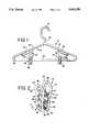
- FIG. 1is a plan view of an all plastic hanger, such as a garment hanger, showing the engagement therewith of a spring clip constructed in accordance with the principles of the present invention
- FIG. 2is a perspective view of a spring clip incorporating the present invention
- FIG. 3is an exploded perspective view of the clip illustrated in FIG. 2;
- FIG. 4is an enlarged sectional view taken along line 4--4 of FIG. 2 with the clip shown in the closed or griping position;
- FIG. 5is a view similar to FIG. 4 with the clip shown in the open position.
- a clip 10incorporating the present invention, as the clip 10 is used with an associated support bar such as the exemplary hanger 12.
- a hangertypically includes a body portion 16 and a supporting hook portion 18 for supporting or suspending the hanger 12 from a support rod, such as a curtain rod or closet rod, as is well known in the art.
- a hanger 12such as that illustrated in FIG. 1, has a cylindrical cross section.
- the body portion 16has an upstanding neck 20 to which is connected the hook portion 18, a cross bar 22, and a pair of arms 24.
- the arms 24merge together at the neck 20, and diverge downward therefrom to join the cross bar 22 at a rounded shoulder 26.
- the diverging arms 24provide a support for a jacket or similar garment.
- the arms 24may also include a slot 28 for supporting garments having straps or the like which would otherwise tend to slip from the arms 24.
- Hangerssuch as that illustrated in FIG. 1 may be used with spring clips, as is well known in the art.
- Typical of such spring clipsis that disclosed in the aforementioned U.S. Pat. No. Re 32,269, which clips use the support bar as a fulcrum for the clip and which support bar then serves as an integral part of the functioning clip.
- the novel clip 10 described hereinmay be similarly attached to a hanger cross bar 22 or the clip 10 may be used independently therefrom.
- the clip 10 of the present inventioncomprises a pair of substantially identical levers or jaw members 50 and a biasing or spring member 52 which connects the jaws together and which serves as a fulcrum and a support about which the jaws 50 pivot, as described herein.
- Each of the jaws 50is formed of a plastic material, such as polypropylene and the like, while the biasing or spring member 52 may be formed from a different material, such as polycarbonate, such materials being recognized by those skilled in the art.
- Each of the jaw members 50is formed as a substantially planar member having an enlarged manually actuatable end portion 54, an intermediate portion 56, and a gripping end portion 58.
- the intermediate portion 56has a closed sidewall 60 extending along a substantial portion thereof, and defines a curvilinear or arcuate surface 62 on the interior side of the jaw member 50 when the clip 10 is viewed in an assembled fashion.
- the gripping end portion 58may have a projection 64 extending inwardly therefrom, as best shown in FIGS. 3 through 5.
- the surface of the projection 64may include ridges or serrations 66 to frictionally secure a garment or other object in the clip 10.
- Each jaw 50is disposed side by side.
- Each jaw 50includes an opening 68 extending from the manually actuatable portion 54 along a part of the intermediate portion 56 to the closed sidewall 60.
- the opening 68receives the legs 70 of the resilient biasing means or U-shaped spring clip portion 72 of the spring member 52.
- the legs 70pass through the opening 68 with the free ends 74 of the legs 70 each engaging a shoulder or detent 76 on the outer surface of the sidewall 60 adjacent the gripping end portion 58.
- the free end 74includes a hook portion 78 which positively engages the detent 76.
- the width of the legs 70 of the U-shaped clip 72is such as to pass through the openings 68 and over the closed sidewall portions 60.
- the legs 70are joined by a curvilinear or arcuate central or base portion 78.
- the spring member 52further includes an arcuate support portion 80, spaced from and interior to the clip 72, and joined thereto by a bridge-like member 81.
- the biasing member 52is formed as a single component, such as in a molding process.
- the arcuate support portion 80is generally coaxial with the central portion 78, as best seen in FIG. 4.
- the central portion 78 and support portion 80define an arcuate or curvilinear channel 82 therebetween.
- the support portion 80extends laterally beyond the width of the legs 70, as best seen in FIGS. 2 and 3.
- the configuration of the U-shaped spring clip 72permits the closed sidewall 60 to be partially positioned in the channel 82, between the central portion 78 and the support portion 80.
- the outer surfaces of the support portion 80engage the corresponding opposed arcuate intermediate surfaces 62 of each jaw member, as best shown in FIGS. 4 and 5.
- the support portion 80thus defines a fulcrum and pivot surface about which the jaws 50 rotate.
- the sidewall portion 60will arcuately traverse through the channel 82 from a lowermost point when the clip 10 is in the gripping position, to an uppermost point when the clip 10 is in the open position.
- the free ends 74 of the legs 70traverse or slide along the intermediate portions 56 of the jaw members 50, in a direction toward the gripping end portions 58, and away from the detents 76.
- the support portion 80tends to move slightly inward (i.e., reduce diameter) and pinch the associated cross-bar 22. This is due to the pressure exerted by the jaw members 50 on the support portion 80 surfaces, as they pivot thereabout. Conversely, when pressure on the actuatable end portion 54 is released and the clip 10 returns to the gripping position, as shown in FIG. 4, the support portion 80 returns to its original shape due to the reduced pressure, and the support portion's 80 resiliency.
- the configuration of the clip 10, having the closed sidewall portion 60 disposed in the channel 82permits the biasing member 52 to be independently or individually secured to either jaw member 50, without the opposing jaw member 50 in place.
- This arrangementfacilitates assembly of the clip 10 and reduces the opportunity to misplace or lose the biasing member 52 when the clip 10 is not fully assembled, or when the clip 10 is disassembled.
- This arrangementalso provides greater resistance to separation and disengagement of the jaw members 50 from the biasing member 52.
- the arcuate support member 80defines an arcuate recess or axial opening 84 formed therewithin which extends along the axis of rotation.
- the axial opening 84is adapted to permit insertion of a suitable support member or rod, such as the exemplary support rod 22 of hanger 12, into the clip 10.
- the support member 80thus retains the rod 22 securely therein, independent of the use or actuation of the clip 10.
- the support member 80may further include projections 86 to facilitate retention of the support rod therein.
- the assembled clip 10is independently operable by virtue of the jaws 50 pivoting about the arcuate fulcrum of the support member 80.
- the opposed gripping end portions 58 of the jaws 50form a nip of the clip with the projections 64 engageable against each other to retain an article therebetween.
- the opposed manually actuatable portions 54are designed to be grasped and pressed together to open the gripping end portions 58 and allow insertion of an article.
- the biasing member 52Upon release of the pressure on the manually actuatable portions 54, the biasing member 52 effects rotation or pivoting of the jaw members 50 about the support portion 80 to force the gripping end portions 58 toward each other to close the clip 10.
- the outer surface of the sidewall portion 60 of the intermediate portion 56 of each jaw member 50may include an inclined or ramped surface 88 extending along the sidewall portion 60 to the detent 76.
- the inclined surface 88facilitates assembly of the clip 10.
- the support portion 80retains its grip or securement on an associated support rod, such as a hanger cross bar 22 when the clip 10 is actuated between the closed or gripping position and the open position. Moreover, because of the interaction of the curvilinear surfaces 62 and the support portion 80 as the surfaces 62 pivot thereon, the grip of the support portion 80 on the cross bar 22 may tend to increase and thus resist sliding and disengagement therefrom.
- the clip 10can be readily snapped onto a suitable support rod, such as a hanger cross bar.
- a suitable support rodsuch as a hanger cross bar.
- the clip 10may be used without the associated support rod. If desired, an alternate support may be used.
- the clipmay be used without any support member and may be hung from a hook or the like passing through the aperture formed in the manually actuatable end thereof.
Landscapes
- Engineering & Computer Science (AREA)
- Textile Engineering (AREA)
- Clamps And Clips (AREA)
- Sheet Holders (AREA)
Abstract
Description
Claims (14)
Priority Applications (7)
| Application Number | Priority Date | Filing Date | Title |
|---|---|---|---|
| US08/239,734US5402558A (en) | 1994-05-09 | 1994-05-09 | Resilient clip |
| CA002148042ACA2148042A1 (en) | 1994-05-09 | 1995-04-27 | Resilient clip |
| FR9505394AFR2719459B1 (en) | 1994-05-09 | 1995-05-05 | Elastic pliers. |
| AU17928/95AAU1792895A (en) | 1994-05-09 | 1995-05-08 | Resilient clip |
| GB9509382AGB2289307A (en) | 1994-05-09 | 1995-05-09 | Resilient clip |
| JP7110874AJPH0842525A (en) | 1994-05-09 | 1995-05-09 | Elastic clip |
| DE19517004ADE19517004A1 (en) | 1994-05-09 | 1995-05-09 | Elastic clamp |
Applications Claiming Priority (1)
| Application Number | Priority Date | Filing Date | Title |
|---|---|---|---|
| US08/239,734US5402558A (en) | 1994-05-09 | 1994-05-09 | Resilient clip |
Publications (1)
| Publication Number | Publication Date |
|---|---|
| US5402558Atrue US5402558A (en) | 1995-04-04 |
Family
ID=22903490
Family Applications (1)
| Application Number | Title | Priority Date | Filing Date |
|---|---|---|---|
| US08/239,734Expired - LifetimeUS5402558A (en) | 1994-05-09 | 1994-05-09 | Resilient clip |
Country Status (7)
| Country | Link |
|---|---|
| US (1) | US5402558A (en) |
| JP (1) | JPH0842525A (en) |
| AU (1) | AU1792895A (en) |
| CA (1) | CA2148042A1 (en) |
| DE (1) | DE19517004A1 (en) |
| FR (1) | FR2719459B1 (en) |
| GB (1) | GB2289307A (en) |
Cited By (60)
| Publication number | Priority date | Publication date | Assignee | Title |
|---|---|---|---|---|
| US5457858A (en)* | 1994-11-07 | 1995-10-17 | Lin; Mao-Chuan | Clip |
| US5535970A (en)* | 1993-10-20 | 1996-07-16 | Gobbi; Gianfranco | Universal clamp for supporting the wall mounted piping of external electrical, telephone or plumbing systems |
| US5595331A (en)* | 1994-08-30 | 1997-01-21 | Leistner; Corinna | Clamping coat hanger for garments |
| US5621955A (en)* | 1992-12-11 | 1997-04-22 | Schmid; Dieter | Clamp made of plastic for clamping sheet-like objects |
| US5625931A (en)* | 1995-08-16 | 1997-05-06 | Visser; Steven C. | Resilient clamp |
| EP0784115A3 (en)* | 1996-01-09 | 1998-01-07 | NKG Co., Ltd. | Clothespin and clothes-equipment |
| US5802677A (en)* | 1996-11-06 | 1998-09-08 | Lilly Industries (Usa), Inc. | Bag closure clip |
| USD409400S (en)* | 1996-11-14 | 1999-05-11 | Mainetti Canada Inc. | Garment clip |
| US6023818A (en)* | 1998-02-26 | 2000-02-15 | Shang; Chen Shui | Spring-biased clip mechanism |
| CN1063503C (en)* | 1996-01-09 | 2001-03-21 | 株式会社艾奴凯吉 | Cloth hanging clip and hanger for drying |
| US6223665B1 (en)* | 2000-02-08 | 2001-05-01 | Lora L. Hindsley | Quilt clamp |
| US6393675B1 (en)* | 1996-02-16 | 2002-05-28 | Hubert J. Gaetke | Method and device for retaining partially rolled-up collapsible containers |
| US6446567B2 (en) | 2000-02-08 | 2002-09-10 | Lora L. Hindsley | Portable hand-operated machine quilting clamp |
| US6612000B2 (en) | 2002-01-07 | 2003-09-02 | Acotex Far East Limited | Bottom hanger clothes clip |
| EP1288017A3 (en)* | 2001-08-29 | 2003-09-17 | Axel Fischer | Holder to releasably attach an object on fabric articles |
| US20040144813A1 (en)* | 2002-11-08 | 2004-07-29 | Louw Henry John | Hanger with soft pad |
| US6826811B2 (en)* | 2002-06-21 | 2004-12-07 | Adams Mfg. Corp. | Jaw-type clip |
| US20050150101A1 (en)* | 2004-01-14 | 2005-07-14 | Paul Langer | Apparatus and method for holding an object |
| US20050241621A1 (en)* | 2002-08-09 | 2005-11-03 | Siemens Akiengesellschaft | Suction jet pump |
| USD515412S1 (en) | 2005-03-11 | 2006-02-21 | Sherwood Services Ag | Drape clip |
| US20060042050A1 (en)* | 2004-08-26 | 2006-03-02 | Hideo Misumi | Synthetic resin clip and hanger with synthetic resin clips |
| USD521856S1 (en) | 2005-03-31 | 2006-05-30 | Sherwood Services Ag | Drape clip |
| US20060179806A1 (en)* | 2005-01-14 | 2006-08-17 | Andreas Stihl Ag & Co. Kg | Carrying system for an implement and method for cutting trees |
| US20060220502A1 (en)* | 2005-03-21 | 2006-10-05 | Williams John W | Storage cabinet for clothing accessories |
| US20070119880A1 (en)* | 2004-11-30 | 2007-05-31 | Mechanix Wear, Inc. | Garment hanger |
| US20080000935A1 (en)* | 2006-06-19 | 2008-01-03 | Austin Joseph E | Kilt hanger |
| US20080093398A1 (en)* | 2006-09-14 | 2008-04-24 | Acotex Far East Limited | Bottom Mount Hanger |
| ES2297956A1 (en)* | 2004-05-05 | 2008-05-01 | Pedro Iglesias Fernandez | Clip for fixing and pairing up socks, is made of plastic and is designed to be directly placed in machine, where dirty socks are washed |
| US20090083954A1 (en)* | 2007-10-02 | 2009-04-02 | Daniel Hunter Hoggan | Versatile Tube Clip Device |
| ES2325290A1 (en)* | 2007-04-17 | 2009-08-31 | Maip, S.L. | Perfected clamp (Machine-translation by Google Translate, not legally binding) |
| US20110000940A1 (en)* | 2009-07-01 | 2011-01-06 | Traci Linn Reilly | Hanger System |
| US7887112B1 (en)* | 2009-11-25 | 2011-02-15 | Levenson Donald R | Food clip utensil |
| USD632954S1 (en)* | 2010-01-18 | 2011-02-22 | Magpul Industries Corporation | Snap clip for a sling |
| FR2951058A1 (en)* | 2009-10-12 | 2011-04-15 | Ind Distrib Service Ids | Device for suspension of articles e.g. boots, has clip element and hook element freely moved with respect to each other as two links of chain when elements are fixed with one other by fixing unit |
| US20120111903A1 (en)* | 2010-11-04 | 2012-05-10 | Choi Ii Young | Men's suit hanger with 'L' shaped elongated clip wing for holding a long men's trouser in a short closet |
| US20120159748A1 (en)* | 2010-12-22 | 2012-06-28 | Interdesign, Inc. | Shower caddy clip and sleeve |
| USD679580S1 (en) | 2011-08-26 | 2013-04-09 | Magpul Industries Corporation | Snap clip |
| US8534626B1 (en)* | 2010-01-19 | 2013-09-17 | Brica, Inc. | Dual-configuration hanger |
| US20130277400A1 (en)* | 2012-04-06 | 2013-10-24 | Joseph Michael Meyer | Form for curved shirt collars |
| US8756771B1 (en) | 2012-12-26 | 2014-06-24 | Ty-Flot, Inc. | Locking clip assembly |
| USD710480S1 (en) | 2013-05-02 | 2014-08-05 | Magpul Industries Corporation | Adjustment buckle for a sling |
| US20150076094A1 (en)* | 2014-02-25 | 2015-03-19 | Edward Allahverdian | Easy Tie Hanger |
| USD726530S1 (en) | 2013-05-06 | 2015-04-14 | Magpul Industries Corporation | Dual drive screw head |
| US20160008001A1 (en)* | 2013-11-21 | 2016-01-14 | Atricure, Inc. | Occlusion clip |
| US9265297B2 (en)* | 2014-07-22 | 2016-02-23 | Kranos Ip Corporation | Face guard retaining device |
| US9427037B1 (en)* | 2013-02-26 | 2016-08-30 | Debra Ann Atherton | Clip for fabric and method of use |
| US20170030141A1 (en)* | 2015-07-28 | 2017-02-02 | Robert Marion Cato | Window Blind Clips and Method of Use |
| US9961953B1 (en)* | 2016-12-15 | 2018-05-08 | Kranos Ip Corporation | Helmet faceguard retaining device |
| US10161429B2 (en)* | 2016-09-27 | 2018-12-25 | Dango Design, LLC | Quick attach accessory mount |
| US10226117B1 (en) | 2015-12-04 | 2019-03-12 | Prop-it, LLC | Holder for portable electronic device and method |
| USD844044S1 (en) | 2017-02-01 | 2019-03-26 | Dango Design, LLC | Quick attach accessory mount |
| US20200163443A1 (en)* | 2018-11-27 | 2020-05-28 | Yuh-Lin Huang | Clip of spring plate type |
| WO2021092469A1 (en)* | 2019-11-07 | 2021-05-14 | Rubenstein Jenna Hally | Clothes hanger clips |
| US11230336B2 (en)* | 2018-03-23 | 2022-01-25 | Neutron Holdings, Inc. | Device mounting system for a vehicle |
| US20220022676A1 (en)* | 2020-07-27 | 2022-01-27 | Kelsey Elizabeth Reinhart | Hanger apparatus |
| US11883035B2 (en) | 2010-10-27 | 2024-01-30 | Atricure, Inc. | Appendage clamp deployment assist device |
| US12004752B2 (en) | 2012-11-21 | 2024-06-11 | Atricure, Inc. | Occlusion clip |
| US12188607B1 (en)* | 2022-09-07 | 2025-01-07 | Reynaldo V. Alonzo | Compact support stand for a portable electronic device |
| US20250031886A1 (en)* | 2023-07-25 | 2025-01-30 | Whitmor, Inc. | Flocked hanger clip |
| US12256858B2 (en)* | 2021-04-23 | 2025-03-25 | Mainetti S.P.A. | Clip for hangers |
Families Citing this family (2)
| Publication number | Priority date | Publication date | Assignee | Title |
|---|---|---|---|---|
| CN2343415Y (en)* | 1998-07-02 | 1999-10-13 | 陈水上 | Structurally Improved Fixtures |
| DE102012223284B4 (en)* | 2012-12-14 | 2016-06-09 | Kipp Verpachtungen E.K. | Locking arrangement with handle arrangement for securing and releasing one or more components |
Citations (51)
| Publication number | Priority date | Publication date | Assignee | Title |
|---|---|---|---|---|
| US454579A (en)* | 1891-06-23 | Suspension-frame for garments | ||
| US1151556A (en)* | 1913-10-17 | 1915-08-31 | Frank P Barney | Garment-clasp. |
| US1358560A (en)* | 1919-09-27 | 1920-11-09 | Kennison Willis Eugene | Tie-clip |
| US1684721A (en)* | 1926-09-11 | 1928-09-18 | Andrew T Wood | Clothespin |
| GB302326A (en)* | 1927-12-15 | 1929-10-24 | Fritz Lachmann | |
| US1750905A (en)* | 1927-04-01 | 1930-03-18 | Schilpp Helen | Stocking hanger |
| US1893508A (en)* | 1930-03-17 | 1933-01-10 | Rosenberg Solomon | Garment hanger |
| US1905958A (en)* | 1932-08-25 | 1933-04-25 | Bogley Preston Pearce | Rubber clothespin |
| GB593125A (en)* | 1945-08-10 | 1947-10-08 | Leon Beilin | Improvements in and relating to spring clip devices |
| US2496109A (en)* | 1945-11-01 | 1950-01-31 | George C Terry | Clothes clamp |
| US2506510A (en)* | 1947-12-02 | 1950-05-02 | Charles P Longwell | Garment hanger |
| CH277009A (en)* | 1949-12-10 | 1951-08-15 | Wagner Maschinen & Werkzeugbau | Clothespin. |
| US2569371A (en)* | 1950-02-09 | 1951-09-25 | Cohen William | Pivoted spring clip |
| CH278907A (en)* | 1950-02-02 | 1951-11-15 | Gogel Piaget Robert | Spring clip. |
| US2583996A (en)* | 1949-10-18 | 1952-01-29 | John J Cavanagh | Garment hanger |
| US2583784A (en)* | 1949-02-08 | 1952-01-29 | Maccaferri Mario | Clip for clothes racks |
| US2613857A (en)* | 1947-10-03 | 1952-10-14 | Victor H Pechtel | Garment hanger |
| GB697866A (en)* | 1951-03-29 | 1953-09-30 | Universal Injection Plastics L | Improvements relating to spring clips |
| US2666240A (en)* | 1951-02-19 | 1954-01-19 | Maccaferri Mario | Clip for clothes racks |
| GB714990A (en)* | 1952-01-29 | 1954-09-08 | Harry Alexander Place | Improved clothes peg |
| GB731906A (en)* | 1952-11-26 | 1955-06-15 | Karl Hugo Bernhard Bergqvist | Improvements in clothes pegs |
| US2723786A (en)* | 1953-04-10 | 1955-11-15 | Edward A Martin | Garment hanger |
| US2782482A (en)* | 1955-05-09 | 1957-02-26 | Hobar Inc | Hanging clip |
| US2802610A (en)* | 1954-09-02 | 1957-08-13 | Lier Philomene Alma De | Garment hangers |
| FR1159796A (en)* | 1956-09-12 | 1958-07-02 | One-piece non-removable clothespin | |
| US2910753A (en)* | 1957-01-25 | 1959-11-03 | Petcar Res Corp | Clothespin |
| FR1210426A (en)* | 1958-09-26 | 1960-03-08 | Paul Clerc & Cie | Improvements to skirt hangers, trouser hangers and the like |
| CH352309A (en)* | 1958-09-16 | 1961-02-28 | Martinaud Roland | Clothespin |
| US3018026A (en)* | 1959-09-29 | 1962-01-23 | William J Binkley | Lingerie dryer |
| US3203061A (en)* | 1962-05-22 | 1965-08-31 | Ekco Products Company | Clamping unit for clothes hanger |
| US3214813A (en)* | 1963-12-23 | 1965-11-02 | Goldman Percy | Garment fastener |
| US3239902A (en)* | 1964-01-22 | 1966-03-15 | Cohen Maurice | Spring clip and boot therefor |
| US3456262A (en)* | 1967-09-15 | 1969-07-15 | Hercules Clip Corp | Clamping device |
| CH504574A (en)* | 1969-03-14 | 1971-03-15 | Neuer Arthur | Device for hanging laundry |
| NL7306492A (en)* | 1972-03-04 | 1974-11-12 | ||
| JPS5057635A (en)* | 1973-09-22 | 1975-05-20 | ||
| US3950829A (en)* | 1974-06-03 | 1976-04-20 | Maurice Cohen | Hanger clip |
| US4009807A (en)* | 1975-12-11 | 1977-03-01 | Red Wing Products Inc. | Garment hanger |
| USD251345S (en) | 1977-10-25 | 1979-03-20 | Jeffrey Alan Bigelow | Garment hanger clip |
| JPS5443859A (en)* | 1977-09-14 | 1979-04-06 | Hitachi Ltd | Detecting method for slip |
| USD264662S (en) | 1980-03-20 | 1982-06-01 | Independent Products Company, Inc. | Spring clip |
| US4382531A (en)* | 1980-04-07 | 1983-05-10 | Independent Products Company, Inc. | Hanger with swivel hook and skirt and trouser clips |
| USRE32269E (en)* | 1980-04-07 | 1986-10-28 | Independent Products Company, Inc. | Plastic clip |
| US4660750A (en)* | 1985-10-23 | 1987-04-28 | Batts, Inc. | Garment hanger with improved wire support |
| US4701983A (en)* | 1985-07-09 | 1987-10-27 | Warmath John G | Clothes clip for a hanger |
| USD301661S (en) | 1987-05-27 | 1989-06-20 | Spotless Plastics Pty. Ltd. | Garment hanger |
| US4878276A (en)* | 1987-06-25 | 1989-11-07 | Peter G. A. Morrish | Spring clip |
| USD307833S (en) | 1987-08-24 | 1990-05-15 | Soko Co., Ltd. | Clip clothes hanger |
| USD316333S (en) | 1988-10-07 | 1991-04-23 | Soko Co., Ltd. | Clip for a clothes hanger |
| US5075935A (en)* | 1990-06-12 | 1991-12-31 | Abdi Abraham M | Garment hanger and clip |
| US5241728A (en)* | 1992-06-08 | 1993-09-07 | Selfix, Inc. | Resilient clip |
Family Cites Families (1)
| Publication number | Priority date | Publication date | Assignee | Title |
|---|---|---|---|---|
| FR979339A (en)* | 1949-01-21 | 1951-04-25 | Plastic clothespin in any color, transparent or opaque |
- 1994
- 1994-05-09USUS08/239,734patent/US5402558A/ennot_activeExpired - Lifetime
- 1995
- 1995-04-27CACA002148042Apatent/CA2148042A1/ennot_activeAbandoned
- 1995-05-05FRFR9505394Apatent/FR2719459B1/ennot_activeExpired - Fee Related
- 1995-05-08AUAU17928/95Apatent/AU1792895A/ennot_activeAbandoned
- 1995-05-09JPJP7110874Apatent/JPH0842525A/enactivePending
- 1995-05-09GBGB9509382Apatent/GB2289307A/ennot_activeWithdrawn
- 1995-05-09DEDE19517004Apatent/DE19517004A1/ennot_activeWithdrawn
Patent Citations (52)
| Publication number | Priority date | Publication date | Assignee | Title |
|---|---|---|---|---|
| US454579A (en)* | 1891-06-23 | Suspension-frame for garments | ||
| US1151556A (en)* | 1913-10-17 | 1915-08-31 | Frank P Barney | Garment-clasp. |
| US1358560A (en)* | 1919-09-27 | 1920-11-09 | Kennison Willis Eugene | Tie-clip |
| US1684721A (en)* | 1926-09-11 | 1928-09-18 | Andrew T Wood | Clothespin |
| US1750905A (en)* | 1927-04-01 | 1930-03-18 | Schilpp Helen | Stocking hanger |
| GB302326A (en)* | 1927-12-15 | 1929-10-24 | Fritz Lachmann | |
| US1893508A (en)* | 1930-03-17 | 1933-01-10 | Rosenberg Solomon | Garment hanger |
| US1905958A (en)* | 1932-08-25 | 1933-04-25 | Bogley Preston Pearce | Rubber clothespin |
| GB593125A (en)* | 1945-08-10 | 1947-10-08 | Leon Beilin | Improvements in and relating to spring clip devices |
| US2496109A (en)* | 1945-11-01 | 1950-01-31 | George C Terry | Clothes clamp |
| US2613857A (en)* | 1947-10-03 | 1952-10-14 | Victor H Pechtel | Garment hanger |
| US2506510A (en)* | 1947-12-02 | 1950-05-02 | Charles P Longwell | Garment hanger |
| US2583784A (en)* | 1949-02-08 | 1952-01-29 | Maccaferri Mario | Clip for clothes racks |
| US2583996A (en)* | 1949-10-18 | 1952-01-29 | John J Cavanagh | Garment hanger |
| CH277009A (en)* | 1949-12-10 | 1951-08-15 | Wagner Maschinen & Werkzeugbau | Clothespin. |
| CH278907A (en)* | 1950-02-02 | 1951-11-15 | Gogel Piaget Robert | Spring clip. |
| US2569371A (en)* | 1950-02-09 | 1951-09-25 | Cohen William | Pivoted spring clip |
| US2666240A (en)* | 1951-02-19 | 1954-01-19 | Maccaferri Mario | Clip for clothes racks |
| GB697866A (en)* | 1951-03-29 | 1953-09-30 | Universal Injection Plastics L | Improvements relating to spring clips |
| GB714990A (en)* | 1952-01-29 | 1954-09-08 | Harry Alexander Place | Improved clothes peg |
| GB731906A (en)* | 1952-11-26 | 1955-06-15 | Karl Hugo Bernhard Bergqvist | Improvements in clothes pegs |
| US2723786A (en)* | 1953-04-10 | 1955-11-15 | Edward A Martin | Garment hanger |
| US2802610A (en)* | 1954-09-02 | 1957-08-13 | Lier Philomene Alma De | Garment hangers |
| US2782482A (en)* | 1955-05-09 | 1957-02-26 | Hobar Inc | Hanging clip |
| FR1159796A (en)* | 1956-09-12 | 1958-07-02 | One-piece non-removable clothespin | |
| US2910753A (en)* | 1957-01-25 | 1959-11-03 | Petcar Res Corp | Clothespin |
| CH352309A (en)* | 1958-09-16 | 1961-02-28 | Martinaud Roland | Clothespin |
| FR1210426A (en)* | 1958-09-26 | 1960-03-08 | Paul Clerc & Cie | Improvements to skirt hangers, trouser hangers and the like |
| US3018026A (en)* | 1959-09-29 | 1962-01-23 | William J Binkley | Lingerie dryer |
| US3203061A (en)* | 1962-05-22 | 1965-08-31 | Ekco Products Company | Clamping unit for clothes hanger |
| GB1031886A (en)* | 1962-05-22 | 1966-06-02 | Ekco Products Company | Clamping unit |
| US3214813A (en)* | 1963-12-23 | 1965-11-02 | Goldman Percy | Garment fastener |
| US3239902A (en)* | 1964-01-22 | 1966-03-15 | Cohen Maurice | Spring clip and boot therefor |
| US3456262A (en)* | 1967-09-15 | 1969-07-15 | Hercules Clip Corp | Clamping device |
| CH504574A (en)* | 1969-03-14 | 1971-03-15 | Neuer Arthur | Device for hanging laundry |
| NL7306492A (en)* | 1972-03-04 | 1974-11-12 | ||
| JPS5057635A (en)* | 1973-09-22 | 1975-05-20 | ||
| US3950829A (en)* | 1974-06-03 | 1976-04-20 | Maurice Cohen | Hanger clip |
| US4009807A (en)* | 1975-12-11 | 1977-03-01 | Red Wing Products Inc. | Garment hanger |
| JPS5443859A (en)* | 1977-09-14 | 1979-04-06 | Hitachi Ltd | Detecting method for slip |
| USD251345S (en) | 1977-10-25 | 1979-03-20 | Jeffrey Alan Bigelow | Garment hanger clip |
| USD264662S (en) | 1980-03-20 | 1982-06-01 | Independent Products Company, Inc. | Spring clip |
| US4382531A (en)* | 1980-04-07 | 1983-05-10 | Independent Products Company, Inc. | Hanger with swivel hook and skirt and trouser clips |
| USRE32269E (en)* | 1980-04-07 | 1986-10-28 | Independent Products Company, Inc. | Plastic clip |
| US4701983A (en)* | 1985-07-09 | 1987-10-27 | Warmath John G | Clothes clip for a hanger |
| US4660750A (en)* | 1985-10-23 | 1987-04-28 | Batts, Inc. | Garment hanger with improved wire support |
| USD301661S (en) | 1987-05-27 | 1989-06-20 | Spotless Plastics Pty. Ltd. | Garment hanger |
| US4878276A (en)* | 1987-06-25 | 1989-11-07 | Peter G. A. Morrish | Spring clip |
| USD307833S (en) | 1987-08-24 | 1990-05-15 | Soko Co., Ltd. | Clip clothes hanger |
| USD316333S (en) | 1988-10-07 | 1991-04-23 | Soko Co., Ltd. | Clip for a clothes hanger |
| US5075935A (en)* | 1990-06-12 | 1991-12-31 | Abdi Abraham M | Garment hanger and clip |
| US5241728A (en)* | 1992-06-08 | 1993-09-07 | Selfix, Inc. | Resilient clip |
Cited By (80)
| Publication number | Priority date | Publication date | Assignee | Title |
|---|---|---|---|---|
| US5621955A (en)* | 1992-12-11 | 1997-04-22 | Schmid; Dieter | Clamp made of plastic for clamping sheet-like objects |
| US5535970A (en)* | 1993-10-20 | 1996-07-16 | Gobbi; Gianfranco | Universal clamp for supporting the wall mounted piping of external electrical, telephone or plumbing systems |
| US5595331A (en)* | 1994-08-30 | 1997-01-21 | Leistner; Corinna | Clamping coat hanger for garments |
| US5457858A (en)* | 1994-11-07 | 1995-10-17 | Lin; Mao-Chuan | Clip |
| US5625931A (en)* | 1995-08-16 | 1997-05-06 | Visser; Steven C. | Resilient clamp |
| EP0784115A3 (en)* | 1996-01-09 | 1998-01-07 | NKG Co., Ltd. | Clothespin and clothes-equipment |
| CN1063503C (en)* | 1996-01-09 | 2001-03-21 | 株式会社艾奴凯吉 | Cloth hanging clip and hanger for drying |
| US6393675B1 (en)* | 1996-02-16 | 2002-05-28 | Hubert J. Gaetke | Method and device for retaining partially rolled-up collapsible containers |
| US5802677A (en)* | 1996-11-06 | 1998-09-08 | Lilly Industries (Usa), Inc. | Bag closure clip |
| USD409400S (en)* | 1996-11-14 | 1999-05-11 | Mainetti Canada Inc. | Garment clip |
| US6023818A (en)* | 1998-02-26 | 2000-02-15 | Shang; Chen Shui | Spring-biased clip mechanism |
| US6446567B2 (en) | 2000-02-08 | 2002-09-10 | Lora L. Hindsley | Portable hand-operated machine quilting clamp |
| US6223665B1 (en)* | 2000-02-08 | 2001-05-01 | Lora L. Hindsley | Quilt clamp |
| EP1288017A3 (en)* | 2001-08-29 | 2003-09-17 | Axel Fischer | Holder to releasably attach an object on fabric articles |
| US6612000B2 (en) | 2002-01-07 | 2003-09-02 | Acotex Far East Limited | Bottom hanger clothes clip |
| US6826811B2 (en)* | 2002-06-21 | 2004-12-07 | Adams Mfg. Corp. | Jaw-type clip |
| US20050241621A1 (en)* | 2002-08-09 | 2005-11-03 | Siemens Akiengesellschaft | Suction jet pump |
| US7874811B2 (en) | 2002-08-09 | 2011-01-25 | Siemens Aktiengesellschaft | Suction jet pump |
| US20040144813A1 (en)* | 2002-11-08 | 2004-07-29 | Louw Henry John | Hanger with soft pad |
| US20050150101A1 (en)* | 2004-01-14 | 2005-07-14 | Paul Langer | Apparatus and method for holding an object |
| ES2297956A1 (en)* | 2004-05-05 | 2008-05-01 | Pedro Iglesias Fernandez | Clip for fixing and pairing up socks, is made of plastic and is designed to be directly placed in machine, where dirty socks are washed |
| ES2297956B1 (en)* | 2004-05-05 | 2009-08-31 | Pedro Iglesias Fernandez | CLAMP FOR SOCKS. |
| US20060042050A1 (en)* | 2004-08-26 | 2006-03-02 | Hideo Misumi | Synthetic resin clip and hanger with synthetic resin clips |
| US7387223B2 (en)* | 2004-08-26 | 2008-06-17 | Hideo Misumi | Synthetic resin clip and hanger with synthetic resin clips |
| US7886945B2 (en)* | 2004-11-30 | 2011-02-15 | Mechanix Wear, Inc. | Garment hanger |
| US20070119880A1 (en)* | 2004-11-30 | 2007-05-31 | Mechanix Wear, Inc. | Garment hanger |
| US20060179806A1 (en)* | 2005-01-14 | 2006-08-17 | Andreas Stihl Ag & Co. Kg | Carrying system for an implement and method for cutting trees |
| USD515412S1 (en) | 2005-03-11 | 2006-02-21 | Sherwood Services Ag | Drape clip |
| US20060220502A1 (en)* | 2005-03-21 | 2006-10-05 | Williams John W | Storage cabinet for clothing accessories |
| USD521856S1 (en) | 2005-03-31 | 2006-05-30 | Sherwood Services Ag | Drape clip |
| US20080000935A1 (en)* | 2006-06-19 | 2008-01-03 | Austin Joseph E | Kilt hanger |
| US9271591B2 (en)* | 2006-06-19 | 2016-03-01 | Joseph E. Austin | Kilt hanger |
| US20080093398A1 (en)* | 2006-09-14 | 2008-04-24 | Acotex Far East Limited | Bottom Mount Hanger |
| ES2325290B1 (en)* | 2007-04-17 | 2010-05-26 | Maip, S.L. | PERFECTED CLAMP. |
| ES2325290A1 (en)* | 2007-04-17 | 2009-08-31 | Maip, S.L. | Perfected clamp (Machine-translation by Google Translate, not legally binding) |
| US20090083954A1 (en)* | 2007-10-02 | 2009-04-02 | Daniel Hunter Hoggan | Versatile Tube Clip Device |
| US20110000940A1 (en)* | 2009-07-01 | 2011-01-06 | Traci Linn Reilly | Hanger System |
| US8820595B2 (en) | 2009-07-01 | 2014-09-02 | Traci Linn Reilly | Method for using a hanger system |
| US8523027B2 (en)* | 2009-07-01 | 2013-09-03 | Traci Linn Reilly | Hanger system |
| FR2951058A1 (en)* | 2009-10-12 | 2011-04-15 | Ind Distrib Service Ids | Device for suspension of articles e.g. boots, has clip element and hook element freely moved with respect to each other as two links of chain when elements are fixed with one other by fixing unit |
| US7887112B1 (en)* | 2009-11-25 | 2011-02-15 | Levenson Donald R | Food clip utensil |
| USD632954S1 (en)* | 2010-01-18 | 2011-02-22 | Magpul Industries Corporation | Snap clip for a sling |
| US8534626B1 (en)* | 2010-01-19 | 2013-09-17 | Brica, Inc. | Dual-configuration hanger |
| US11883035B2 (en) | 2010-10-27 | 2024-01-30 | Atricure, Inc. | Appendage clamp deployment assist device |
| US20120111903A1 (en)* | 2010-11-04 | 2012-05-10 | Choi Ii Young | Men's suit hanger with 'L' shaped elongated clip wing for holding a long men's trouser in a short closet |
| US20120159748A1 (en)* | 2010-12-22 | 2012-06-28 | Interdesign, Inc. | Shower caddy clip and sleeve |
| US8769781B2 (en)* | 2010-12-22 | 2014-07-08 | Interdesign, Inc. | Shower caddy clip and sleeve |
| USD679580S1 (en) | 2011-08-26 | 2013-04-09 | Magpul Industries Corporation | Snap clip |
| US20130277400A1 (en)* | 2012-04-06 | 2013-10-24 | Joseph Michael Meyer | Form for curved shirt collars |
| US12193680B2 (en) | 2012-11-21 | 2025-01-14 | Atricure, Inc. | Occlusion clip |
| US12004752B2 (en) | 2012-11-21 | 2024-06-11 | Atricure, Inc. | Occlusion clip |
| US8756771B1 (en) | 2012-12-26 | 2014-06-24 | Ty-Flot, Inc. | Locking clip assembly |
| US9427037B1 (en)* | 2013-02-26 | 2016-08-30 | Debra Ann Atherton | Clip for fabric and method of use |
| USD710480S1 (en) | 2013-05-02 | 2014-08-05 | Magpul Industries Corporation | Adjustment buckle for a sling |
| USD726530S1 (en) | 2013-05-06 | 2015-04-14 | Magpul Industries Corporation | Dual drive screw head |
| US12076019B2 (en) | 2013-11-21 | 2024-09-03 | Atricure, Inc. | Occlusion clip |
| US20160008001A1 (en)* | 2013-11-21 | 2016-01-14 | Atricure, Inc. | Occlusion clip |
| US11266413B2 (en)* | 2013-11-21 | 2022-03-08 | Atricure, Inc. | Occlusion clip |
| US11998212B2 (en) | 2013-11-21 | 2024-06-04 | Atricure, Inc. | Occlusion clip |
| US11998211B2 (en) | 2013-11-21 | 2024-06-04 | Atricure, Inc. | Occlusion clip |
| US9357866B2 (en)* | 2014-02-25 | 2016-06-07 | Edward Allahverdian | Clip for hanging a necktie |
| US20150076094A1 (en)* | 2014-02-25 | 2015-03-19 | Edward Allahverdian | Easy Tie Hanger |
| US9265297B2 (en)* | 2014-07-22 | 2016-02-23 | Kranos Ip Corporation | Face guard retaining device |
| US20170030141A1 (en)* | 2015-07-28 | 2017-02-02 | Robert Marion Cato | Window Blind Clips and Method of Use |
| US10226117B1 (en) | 2015-12-04 | 2019-03-12 | Prop-it, LLC | Holder for portable electronic device and method |
| US10161429B2 (en)* | 2016-09-27 | 2018-12-25 | Dango Design, LLC | Quick attach accessory mount |
| US9961953B1 (en)* | 2016-12-15 | 2018-05-08 | Kranos Ip Corporation | Helmet faceguard retaining device |
| USD844044S1 (en) | 2017-02-01 | 2019-03-26 | Dango Design, LLC | Quick attach accessory mount |
| US11230336B2 (en)* | 2018-03-23 | 2022-01-25 | Neutron Holdings, Inc. | Device mounting system for a vehicle |
| US20200163443A1 (en)* | 2018-11-27 | 2020-05-28 | Yuh-Lin Huang | Clip of spring plate type |
| US10813439B2 (en)* | 2018-11-27 | 2020-10-27 | Yuh-Lin Huang | Clip of spring plate type |
| US20220389644A1 (en)* | 2019-11-07 | 2022-12-08 | Jenna Hally Rubenstein | Clothes hanger clips |
| CN114929073A (en)* | 2019-11-07 | 2022-08-19 | 詹娜·哈莉·鲁宾斯坦 | Clothes hanger clamp |
| US20240328060A1 (en)* | 2019-11-07 | 2024-10-03 | Jenna Hally Rubenstein | Clothes hanger clips |
| WO2021092469A1 (en)* | 2019-11-07 | 2021-05-14 | Rubenstein Jenna Hally | Clothes hanger clips |
| US20220022676A1 (en)* | 2020-07-27 | 2022-01-27 | Kelsey Elizabeth Reinhart | Hanger apparatus |
| US11678756B2 (en)* | 2020-07-27 | 2023-06-20 | Kelsey Elizabeth Reinhart | Hanger apparatus |
| US12256858B2 (en)* | 2021-04-23 | 2025-03-25 | Mainetti S.P.A. | Clip for hangers |
| US12188607B1 (en)* | 2022-09-07 | 2025-01-07 | Reynaldo V. Alonzo | Compact support stand for a portable electronic device |
| US20250031886A1 (en)* | 2023-07-25 | 2025-01-30 | Whitmor, Inc. | Flocked hanger clip |
Also Published As
| Publication number | Publication date |
|---|---|
| GB9509382D0 (en) | 1995-06-28 |
| CA2148042A1 (en) | 1995-11-10 |
| FR2719459B1 (en) | 1997-01-17 |
| FR2719459A1 (en) | 1995-11-10 |
| JPH0842525A (en) | 1996-02-13 |
| GB2289307A (en) | 1995-11-15 |
| AU1792895A (en) | 1995-11-16 |
| DE19517004A1 (en) | 1995-11-16 |
Similar Documents
| Publication | Publication Date | Title |
|---|---|---|
| US5402558A (en) | Resilient clip | |
| US5241728A (en) | Resilient clip | |
| US5075935A (en) | Garment hanger and clip | |
| US4335838A (en) | Skirt and trouser clip for hanger | |
| US4382531A (en) | Hanger with swivel hook and skirt and trouser clips | |
| EP0879005B1 (en) | Spring badge clip | |
| US4009807A (en) | Garment hanger | |
| US5590823A (en) | Collapsible garment hanger suitable for rapid one-handed engagement with garment | |
| US4850562A (en) | Hanger-retaining clamp for garment bags | |
| US4209879A (en) | Clamp | |
| USRE32269E (en) | Plastic clip | |
| US4023721A (en) | Garment clamping hanger with spring-biased clamping members | |
| US6779695B2 (en) | Garment hanger | |
| US4618058A (en) | Locking trolley for garment bag | |
| CA1240298A (en) | Locking trolley for hangers | |
| US4600132A (en) | Adjustable hanger | |
| US4044928A (en) | Clothes hanger particularly for skirt, slacks and the like | |
| US6474517B1 (en) | Clamp-type garment hanger | |
| US6499635B1 (en) | Garment hanger | |
| GB2415738A (en) | Clothes peg with releasable securing means | |
| US7441313B2 (en) | Spring clamp with hook | |
| US3984037A (en) | Hand operated garment hanger having simplified closure means | |
| JP7699332B2 (en) | Attachments, clothespins and clothes hangers | |
| CA1155428A (en) | Hanger with swivel hook and skirt and trouser clips | |
| JP7698858B1 (en) | Slide detachable hook |
Legal Events
| Date | Code | Title | Description |
|---|---|---|---|
| AS | Assignment | Owner name:SELFIX, INC., ILLINOIS Free format text:ASSIGNMENT OF ASSIGNORS INTEREST;ASSIGNOR:SANTAPA, FRANK J.;REEL/FRAME:007095/0781 Effective date:19940506 | |
| STCF | Information on status: patent grant | Free format text:PATENTED CASE | |
| AS | Assignment | Owner name:GENERAL ELECTRIC CAPTIAL CORPORATION, AS AGENT, IL Free format text:SECURITY AGREEMENT;ASSIGNOR:SELFIX, INC.;REEL/FRAME:008683/0511 Effective date:19970227 | |
| FEPP | Fee payment procedure | Free format text:PAYOR NUMBER ASSIGNED (ORIGINAL EVENT CODE: ASPN); ENTITY STATUS OF PATENT OWNER: LARGE ENTITY | |
| FPAY | Fee payment | Year of fee payment:4 | |
| AS | Assignment | Owner name:CHASE MANHATTAN BANK, THE, AS ADMINISTRATIVE AGENT Free format text:SECURITY INTEREST;ASSIGNORS:HOME PRODUCTS INTERNATIONAL, INC. (DE CORPORATION);SELFIX, INC. (DE CORPORATION);TAMOR CORPORATION (MA CORPORATION);AND OTHERS;REEL/FRAME:009580/0357 Effective date:19980908 | |
| AS | Assignment | Owner name:HOME PRODUCTS INTERNATIONAL, INC., ILLINOIS Free format text:TERMINATION AND RELEASE OF SECURITY INTEREST IN PATENT RIGHTS RECORDED AT REEL 9580 FRAME 0357;ASSIGNOR:CHASE MANHATTAN BANK, THE, AS ADMINISTRATIVE AGENT;REEL/FRAME:012483/0852 Effective date:20011031 Owner name:SELFIX, INC., ILLINOIS Free format text:TERMINATION AND RELEASE OF SECURITY INTEREST IN PATENT RIGHTS RECORDED AT REEL 9580 FRAME 0357;ASSIGNOR:CHASE MANHATTAN BANK, THE, AS ADMINISTRATIVE AGENT;REEL/FRAME:012483/0852 Effective date:20011031 Owner name:TAMOR CORPORATION, ILLINOIS Free format text:TERMINATION AND RELEASE OF SECURITY INTEREST IN PATENT RIGHTS RECORDED AT REEL 9580 FRAME 0357;ASSIGNOR:CHASE MANHATTAN BANK, THE, AS ADMINISTRATIVE AGENT;REEL/FRAME:012483/0852 Effective date:20011031 Owner name:SEYMOUR HOUSWARES CORPORATION, ILLINOIS Free format text:TERMINATION AND RELEASE OF SECURITY INTEREST IN PATENT RIGHTS RECORDED AT REEL 9580 FRAME 0357;ASSIGNOR:CHASE MANHATTAN BANK, THE, AS ADMINISTRATIVE AGENT;REEL/FRAME:012483/0852 Effective date:20011031 Owner name:SHUTTERS, INC., ILLINOIS Free format text:TERMINATION AND RELEASE OF SECURITY INTEREST IN PATENT RIGHTS RECORDED AT REEL 9580 FRAME 0357;ASSIGNOR:CHASE MANHATTAN BANK, THE, AS ADMINISTRATIVE AGENT;REEL/FRAME:012483/0852 Effective date:20011031 Owner name:PRESTIGE PLASTICS, INC., ILLINOIS Free format text:TERMINATION AND RELEASE OF SECURITY INTEREST IN PATENT RIGHTS RECORDED AT REEL 9580 FRAME 0357;ASSIGNOR:CHASE MANHATTAN BANK, THE, AS ADMINISTRATIVE AGENT;REEL/FRAME:012483/0852 Effective date:20011031 | |
| FPAY | Fee payment | Year of fee payment:8 | |
| FEPP | Fee payment procedure | Free format text:PAT HOLDER NO LONGER CLAIMS SMALL ENTITY STATUS, ENTITY STATUS SET TO UNDISCOUNTED (ORIGINAL EVENT CODE: STOL); ENTITY STATUS OF PATENT OWNER: LARGE ENTITY | |
| REFU | Refund | Free format text:REFUND - PAYMENT OF MAINTENANCE FEE, 12TH YR, SMALL ENTITY (ORIGINAL EVENT CODE: R2553); ENTITY STATUS OF PATENT OWNER: LARGE ENTITY | |
| FPAY | Fee payment | Year of fee payment:12 | |
| FEPP | Fee payment procedure | Free format text:PAYER NUMBER DE-ASSIGNED (ORIGINAL EVENT CODE: RMPN); ENTITY STATUS OF PATENT OWNER: LARGE ENTITY Free format text:PAYOR NUMBER ASSIGNED (ORIGINAL EVENT CODE: ASPN); ENTITY STATUS OF PATENT OWNER: LARGE ENTITY | |
| AS | Assignment | Owner name:HOME PRODUCTS INTERNATIONAL - NORTH AMERICA, INC., Free format text:CHANGE OF NAME;ASSIGNOR:SELFIX-SEYMOUR HOUSEWARES CORPORATION;REEL/FRAME:026539/0542 Effective date:19990827 Owner name:FCC TRANSITION, LLC, ILLINOIS Free format text:SUCCESSOR TO SECURITY INTEREST BY WAY OF MERGER;ASSIGNOR:FLEET CAPITAL CORPORATION;REEL/FRAME:026539/0577 Effective date:20050731 Owner name:BANC OF AMERICA LEASING & CAPITAL, LLC, ILLINOIS Free format text:SUCCESSOR TO SECURITY INTEREST BY WAY OF MERGER;ASSIGNOR:FCC TRANSITION, LLC;REEL/FRAME:026539/0922 Effective date:20050731 Owner name:FLEET CAPITAL CORPORATION, ILLINOIS Free format text:SECURITY AGREEMENT;ASSIGNOR:HOME PRODUCTS INTERNATIONAL - NORTH AMERICA, INC.;REEL/FRAME:026539/0550 Effective date:20011031 | |
| AS | Assignment | Owner name:HOME PRODUCTS INTERNATIONAL, INC., ILLINOIS Free format text:RELEASE BY SECURED PARTY;ASSIGNOR:BANK OF AMERICA, NATIONAL ASSOCIATION;REEL/FRAME:028405/0435 Effective date:20120619 Owner name:BMO HARRIS BANK N.A., AS AGENT, ILLINOIS Free format text:SECURITY AGREEMENT;ASSIGNORS:HOME PRODUCTS INTERNATIONAL, INC.;HOME PRODUCTS INTERNATIONAL - NORTH AMERICA, INC.;REEL/FRAME:028405/0427 Effective date:20120619 Owner name:HOME PRODUCTS INTERNATIONAL - NORTH AMERICA, INC., Free format text:RELEASE BY SECURED PARTY;ASSIGNOR:BANK OF AMERICA, NATIONAL ASSOCIATION;REEL/FRAME:028405/0435 Effective date:20120619 | |
| AS | Assignment | Owner name:HOME PRODUCTS INTERNATIONAL - NORTH AMERICA, INC., Free format text:RELEASE BY SECURED PARTY;ASSIGNOR:BMO HARRIS BANK N.A.;REEL/FRAME:048478/0809 Effective date:20190228 Owner name:HOME PRODUCTS INTERNATIONAL, INC., ILLINOIS Free format text:RELEASE BY SECURED PARTY;ASSIGNOR:BMO HARRIS BANK N.A.;REEL/FRAME:048478/0809 Effective date:20190228 |