US5402315A - Printed circuit board and assembly module for connection of screened conductors for distribution boards and distribution systems in light-current systems engineering - Google Patents
Printed circuit board and assembly module for connection of screened conductors for distribution boards and distribution systems in light-current systems engineeringDownload PDFInfo
- Publication number
- US5402315A US5402315AUS08/093,673US9367393AUS5402315AUS 5402315 AUS5402315 AUS 5402315AUS 9367393 AUS9367393 AUS 9367393AUS 5402315 AUS5402315 AUS 5402315A
- Authority
- US
- United States
- Prior art keywords
- printed circuit
- module
- circuit board
- assembly module
- connection
- Prior art date
- Legal status (The legal status is an assumption and is not a legal conclusion. Google has not performed a legal analysis and makes no representation as to the accuracy of the status listed.)
- Expired - Fee Related
Links
Images
Classifications
- H—ELECTRICITY
- H05—ELECTRIC TECHNIQUES NOT OTHERWISE PROVIDED FOR
- H05K—PRINTED CIRCUITS; CASINGS OR CONSTRUCTIONAL DETAILS OF ELECTRIC APPARATUS; MANUFACTURE OF ASSEMBLAGES OF ELECTRICAL COMPONENTS
- H05K9/00—Screening of apparatus or components against electric or magnetic fields
- H—ELECTRICITY
- H05—ELECTRIC TECHNIQUES NOT OTHERWISE PROVIDED FOR
- H05K—PRINTED CIRCUITS; CASINGS OR CONSTRUCTIONAL DETAILS OF ELECTRIC APPARATUS; MANUFACTURE OF ASSEMBLAGES OF ELECTRICAL COMPONENTS
- H05K13/00—Apparatus or processes specially adapted for manufacturing or adjusting assemblages of electric components
- H—ELECTRICITY
- H01—ELECTRIC ELEMENTS
- H01R—ELECTRICALLY-CONDUCTIVE CONNECTIONS; STRUCTURAL ASSOCIATIONS OF A PLURALITY OF MUTUALLY-INSULATED ELECTRICAL CONNECTING ELEMENTS; COUPLING DEVICES; CURRENT COLLECTORS
- H01R9/00—Structural associations of a plurality of mutually-insulated electrical connecting elements, e.g. terminal strips or terminal blocks; Terminals or binding posts mounted upon a base or in a case; Bases therefor
- H01R9/03—Connectors arranged to contact a plurality of the conductors of a multiconductor cable, e.g. tapping connections
- H01R9/05—Connectors arranged to contact a plurality of the conductors of a multiconductor cable, e.g. tapping connections for coaxial cables
- H01R9/0515—Connection to a rigid planar substrate, e.g. printed circuit board
- H—ELECTRICITY
- H05—ELECTRIC TECHNIQUES NOT OTHERWISE PROVIDED FOR
- H05K—PRINTED CIRCUITS; CASINGS OR CONSTRUCTIONAL DETAILS OF ELECTRIC APPARATUS; MANUFACTURE OF ASSEMBLAGES OF ELECTRICAL COMPONENTS
- H05K3/00—Apparatus or processes for manufacturing printed circuits
- H05K3/0011—Working of insulating substrates or insulating layers
- H05K3/0044—Mechanical working of the substrate, e.g. drilling or punching
- H05K3/0052—Depaneling, i.e. dividing a panel into circuit boards; Working of the edges of circuit boards
- H—ELECTRICITY
- H01—ELECTRIC ELEMENTS
- H01R—ELECTRICALLY-CONDUCTIVE CONNECTIONS; STRUCTURAL ASSOCIATIONS OF A PLURALITY OF MUTUALLY-INSULATED ELECTRICAL CONNECTING ELEMENTS; COUPLING DEVICES; CURRENT COLLECTORS
- H01R9/00—Structural associations of a plurality of mutually-insulated electrical connecting elements, e.g. terminal strips or terminal blocks; Terminals or binding posts mounted upon a base or in a case; Bases therefor
- H01R9/03—Connectors arranged to contact a plurality of the conductors of a multiconductor cable, e.g. tapping connections
- H01R9/05—Connectors arranged to contact a plurality of the conductors of a multiconductor cable, e.g. tapping connections for coaxial cables
- H01R9/0527—Connection to outer conductor by action of a resilient member, e.g. spring
- H—ELECTRICITY
- H05—ELECTRIC TECHNIQUES NOT OTHERWISE PROVIDED FOR
- H05K—PRINTED CIRCUITS; CASINGS OR CONSTRUCTIONAL DETAILS OF ELECTRIC APPARATUS; MANUFACTURE OF ASSEMBLAGES OF ELECTRICAL COMPONENTS
- H05K2201/00—Indexing scheme relating to printed circuits covered by H05K1/00
- H05K2201/09—Shape and layout
- H05K2201/09009—Substrate related
- H05K2201/09036—Recesses or grooves in insulating substrate
- H—ELECTRICITY
- H05—ELECTRIC TECHNIQUES NOT OTHERWISE PROVIDED FOR
- H05K—PRINTED CIRCUITS; CASINGS OR CONSTRUCTIONAL DETAILS OF ELECTRIC APPARATUS; MANUFACTURE OF ASSEMBLAGES OF ELECTRICAL COMPONENTS
- H05K2201/00—Indexing scheme relating to printed circuits covered by H05K1/00
- H05K2201/09—Shape and layout
- H05K2201/09009—Substrate related
- H05K2201/0909—Preformed cutting or breaking line
- H—ELECTRICITY
- H05—ELECTRIC TECHNIQUES NOT OTHERWISE PROVIDED FOR
- H05K—PRINTED CIRCUITS; CASINGS OR CONSTRUCTIONAL DETAILS OF ELECTRIC APPARATUS; MANUFACTURE OF ASSEMBLAGES OF ELECTRICAL COMPONENTS
- H05K2201/00—Indexing scheme relating to printed circuits covered by H05K1/00
- H05K2201/09—Shape and layout
- H05K2201/09818—Shape or layout details not covered by a single group of H05K2201/09009 - H05K2201/09809
- H05K2201/09827—Tapered, e.g. tapered hole, via or groove
- H—ELECTRICITY
- H05—ELECTRIC TECHNIQUES NOT OTHERWISE PROVIDED FOR
- H05K—PRINTED CIRCUITS; CASINGS OR CONSTRUCTIONAL DETAILS OF ELECTRIC APPARATUS; MANUFACTURE OF ASSEMBLAGES OF ELECTRICAL COMPONENTS
- H05K3/00—Apparatus or processes for manufacturing printed circuits
- H05K3/0058—Laminating printed circuit boards onto other substrates, e.g. metallic substrates
- H05K3/0061—Laminating printed circuit boards onto other substrates, e.g. metallic substrates onto a metallic substrate, e.g. a heat sink
- Y—GENERAL TAGGING OF NEW TECHNOLOGICAL DEVELOPMENTS; GENERAL TAGGING OF CROSS-SECTIONAL TECHNOLOGIES SPANNING OVER SEVERAL SECTIONS OF THE IPC; TECHNICAL SUBJECTS COVERED BY FORMER USPC CROSS-REFERENCE ART COLLECTIONS [XRACs] AND DIGESTS
- Y10—TECHNICAL SUBJECTS COVERED BY FORMER USPC
- Y10T—TECHNICAL SUBJECTS COVERED BY FORMER US CLASSIFICATION
- Y10T24/00—Buckles, buttons, clasps, etc.
- Y10T24/44—Clasp, clip, support-clamp, or required component thereof
- Y10T24/44017—Clasp, clip, support-clamp, or required component thereof with specific mounting means for attaching to rigid or semirigid supporting structure or structure-to-be-secured
- Y—GENERAL TAGGING OF NEW TECHNOLOGICAL DEVELOPMENTS; GENERAL TAGGING OF CROSS-SECTIONAL TECHNOLOGIES SPANNING OVER SEVERAL SECTIONS OF THE IPC; TECHNICAL SUBJECTS COVERED BY FORMER USPC CROSS-REFERENCE ART COLLECTIONS [XRACs] AND DIGESTS
- Y10—TECHNICAL SUBJECTS COVERED BY FORMER USPC
- Y10T—TECHNICAL SUBJECTS COVERED BY FORMER US CLASSIFICATION
- Y10T24/00—Buckles, buttons, clasps, etc.
- Y10T24/44—Clasp, clip, support-clamp, or required component thereof
- Y10T24/44239—Encircling gripping member including semirigid band and operator for tightening
Definitions
- the present inventionrelates to a printed circuit board.
- thisis achieved at first by a multi-modular arrangement of modular connection and switching means, next to one another, the printed circuit board having a rated breakage point between each of the adjacent modules of connection and switching means so as to obtain single-module printed circuit boards by breaking.
- a preferred embodiment of the printed circuit board according to the inventionmay be obtained by a metallic grounding pad extending across the entire length of the printed circuit board and having one rated breakage point each in the extension of the rated breakage points of the printed circuit board for joint separation of the printed circuit board and the grounding pad by breaking.
- the present inventionalso relates to an assembly module for such a printed circuit board for connection of screened conductors for distribution boards and distribution systems in light-current systems engineering.
- a metallic grounding padwhich may be connected with a connection system such as a printed circuit board and the like in a fixed way and on which at least one spring clamp having an approximately shell-shaped conductor accommodating area and designed so as to detachably enclose at least one conductor is supported in a conductive way.
- the metallic grounding padbe formed as a multiple module and possesses a plurality of spring clamps arranged next to one another, the grounding pad having one rated breakage point each between two adjacent spring clamps so as to obtain single modules by breaking.
- the spring clampcould be a spring arm revited to the grounding pad, however, preferably, the spring clamp is U-shaped. This permits a preferred embodiment such that the spring clamp includes at least two conductor accommodating areas on top of one another so as to accommodate conductors of varying diameters.
- the spring clampmay also be used as a strain relief device, or the grounding pad may provide slots for push-through accommodation of a cable coupler.
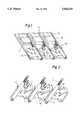
- FIG. 1is a diagrammatic representation of a printed circuit board according to the invention.
- FIG. 2is a diagrammatic representation of an assembly module according to the invention.
- the printed circuit board 1 of FIG. 1is formed in a multi-modular way having connection modules disposed next to one another and formed of, for example, connector module 3 and wire core connection module 2 or the like, and includes a printed circuit corresponding to the relevant application and disposed within the connection module which is not shown herein in further detail.
- this multiple-module printed circuit board 1possesses parallel grooves or the like between the adjacent sets of connection modules 2,3 and disposed at predetermined distances, which form rated breakage points 4 so as to obtain single modules by breaking.
- a metallic grounding pad 21extending across the entire length of the printed circuit board 1 will be mounted which has one rated breakage point 24 each in the extension of the rated breakage points 4 of the printed circuit board 1 for joint separation of printed circuit board and grounding pad by breaking.
- the assembly module of FIG. 2 for the connection of the screened conductor 10 having a stripped conductor area 11includes the multiple-module metallic grounding pad 21 which may be connected in a fixed manner with any connection system, in this case a printed circuit board 1 (FIG. 1), for example, by glueing or by forming bore holes 7 therethrough, by screw-connecting or reviting.
- a printed circuit board 1FIG. 1
- bore holes 6may be used for ground connection by solder-connecting of a grounding conductor.
- the multiple-module grounding pad 21possesses parallel grooves or the like disposed at predetermined distances which form rated breakage points 24 so as to obtain single modules by breaking.
- Each single module of the grounding pad 21 marked in this waycarries one metallic spring clamp 22 and 22', respectively, preferably mounted by riveting 8 or the like, including an approximately shell-shaped conductor accommodating area 33 by which the spring clamps 22 and 22', respectively, enclose the stripped conductor area 11 at least partly in a detachable way and thus form an optimum RF grounding connection between conductor and grounding pad.
- the spring clamps 22 and 22'may also be used as a strain relief device, or the grounding pad 21 may provide slots 5 for push-through accommodation of a cable coupler 9.
- the spring clampmay be formed as tongue spring 22' or be a U-shaped spring clamp 22 preferably including two conductor accommodating areas on top of one another so as to accommodate conductors having varying diameters.
- This embodiment of the assembly modulewhich is preferably manufactured as multiple module and randomly reduced or separated thereafter, permits unlimited use in all areas where screened conductors are to be connected, optimum grounding in terms of RF being ensured.
- the structure of a printed circuit board moduleis fully free without departing from the scope of the concept of invention.
- the multi-modular structure of the printed circuit boardfor example, with the maximum number of adjacent modules of an application, is essential, which printed circuit board may then be separated according to the needs for which purpose mere breaking along the rated breakage point will be required.
Landscapes
- Engineering & Computer Science (AREA)
- Microelectronics & Electronic Packaging (AREA)
- Manufacturing & Machinery (AREA)
- Multi-Conductor Connections (AREA)
- Combinations Of Printed Boards (AREA)
Abstract
Description
The present invention relates to a printed circuit board.
In many areas of installation engineering, especially in light-current systems for telephone and data communications, the number of printed circuit boards used is steadily increasing.
However, it constitutes a problem that there exists a demand for modular and multi-modular printed circuit boards having a varying number of modules and that the structure of the systems concerned is subject to constant changes requiring the use of additional or less printed circuit boards of the specified type.
In stocking of spares, all this requires a large number of modular printed circuit boards with the same components for each of the systems, which is complicated and expensive.
Therefore, it is the primary object of the present invention to provide a printed circuit board fulfilling the formulated requirements of multiple and single modularity, respectively.
According to the invention, this is achieved at first by a multi-modular arrangement of modular connection and switching means, next to one another, the printed circuit board having a rated breakage point between each of the adjacent modules of connection and switching means so as to obtain single-module printed circuit boards by breaking.
Now, these measures permit the preparation of multi-modular printed circuit boards having any number of modules, which will then be suitable for obtaining therefrom single-modular or multi-modular partial boards comprising a smaller number of modules by simple breaking, thereby essentially simplifying manufacture and stocking of spares.
If the printed circuit boards are intended for the connection of electrical conductors, which are screened against interfering external electrical fields by a highly conductive, metallic sleeve, a preferred embodiment of the printed circuit board according to the invention may be obtained by a metallic grounding pad extending across the entire length of the printed circuit board and having one rated breakage point each in the extension of the rated breakage points of the printed circuit board for joint separation of the printed circuit board and the grounding pad by breaking.
Accordingly, the present invention also relates to an assembly module for such a printed circuit board for connection of screened conductors for distribution boards and distribution systems in light-current systems engineering.
In telephone or other signal transmission areas, electric conductors which are screened against interfering external electrical fields are indispensable. However, their placement in the connecting system, such as a printed circuit board and the like, constitutes a problem, especially with regard to optimum grounding of the screening in the conductor connection area in terms of RF.
An assembly module of the above type, which may be used anywhere and in any system for connection of screened conductors and which ensures an optimum RF grounding connection of the conductors will now be rendered possible by a metallic grounding pad which may be connected with a connection system such as a printed circuit board and the like in a fixed way and on which at least one spring clamp having an approximately shell-shaped conductor accommodating area and designed so as to detachably enclose at least one conductor is supported in a conductive way.
In this context, it is essential for the invention that the metallic grounding pad be formed as a multiple module and possesses a plurality of spring clamps arranged next to one another, the grounding pad having one rated breakage point each between two adjacent spring clamps so as to obtain single modules by breaking.
Generally, the spring clamp could be a spring arm revited to the grounding pad, however, preferably, the spring clamp is U-shaped. This permits a preferred embodiment such that the spring clamp includes at least two conductor accommodating areas on top of one another so as to accommodate conductors of varying diameters.
According to the invention, the spring clamp may also be used as a strain relief device, or the grounding pad may provide slots for push-through accommodation of a cable coupler.
Embodiment examples according to the invention will now be described more particularly with reference to the accompanying drawings, wherein:
FIG. 1 is a diagrammatic representation of a printed circuit board according to the invention; and
FIG. 2 is a diagrammatic representation of an assembly module according to the invention.
The printedcircuit board 1 of FIG. 1 is formed in a multi-modular way having connection modules disposed next to one another and formed of, for example,connector module 3 and wirecore connection module 2 or the like, and includes a printed circuit corresponding to the relevant application and disposed within the connection module which is not shown herein in further detail.
According to the invention, this multiple-module printedcircuit board 1 possesses parallel grooves or the like between the adjacent sets ofconnection modules
If the printed circuit boards are intended for the connection of electrical conductors, which are screened against interfering external electrical fields by a highly conductive, metallic sleeve, ametallic grounding pad 21 extending across the entire length of the printedcircuit board 1 will be mounted which has one ratedbreakage point 24 each in the extension of the rated breakage points 4 of the printedcircuit board 1 for joint separation of printed circuit board and grounding pad by breaking.
Such an assembly module will be set forth hereinafter in further detail with reference made to FIG. 2.
In this case, the assembly module of FIG. 2 for the connection of the screenedconductor 10 having a strippedconductor area 11 includes the multiple-modulemetallic grounding pad 21 which may be connected in a fixed manner with any connection system, in this case a printed circuit board 1 (FIG. 1), for example, by glueing or by forming bore holes 7 therethrough, by screw-connecting or reviting.
Further bore holes 6 may be used for ground connection by solder-connecting of a grounding conductor.
The multiple-module grounding pad 21 possesses parallel grooves or the like disposed at predetermined distances which form ratedbreakage points 24 so as to obtain single modules by breaking.
Each single module of thegrounding pad 21 marked in this way carries onemetallic spring clamp 22 and 22', respectively, preferably mounted by riveting 8 or the like, including an approximately shell-shapedconductor accommodating area 33 by which thespring clamps 22 and 22', respectively, enclose the strippedconductor area 11 at least partly in a detachable way and thus form an optimum RF grounding connection between conductor and grounding pad.
It is apparent that a separation of the connection is possible without problems and at any time.
Depending on the spring tension, thespring clamps 22 and 22', respectively, may also be used as a strain relief device, or thegrounding pad 21 may provideslots 5 for push-through accommodation of acable coupler 9.
The spring clamp may be formed as tongue spring 22' or be a U-shapedspring clamp 22 preferably including two conductor accommodating areas on top of one another so as to accommodate conductors having varying diameters.
This embodiment of the assembly module, which is preferably manufactured as multiple module and randomly reduced or separated thereafter, permits unlimited use in all areas where screened conductors are to be connected, optimum grounding in terms of RF being ensured.
Generally, the structure of a printed circuit board module is fully free without departing from the scope of the concept of invention. The multi-modular structure of the printed circuit board, for example, with the maximum number of adjacent modules of an application, is essential, which printed circuit board may then be separated according to the needs for which purpose mere breaking along the rated breakage point will be required.
While there are shown and described preferred embodiments of the invention, it is to be distinctly understood that the invention is not limited thereto but may be embodied and practised within the scope of the following claims. Accordingly,
Claims (5)
1. An assembly module for a printed circuit board for the connection of screened conductors, comprising:
a metallic grounding plate comprising multiple modules, each said module including means for fixedly connecting the module to a printed circuit board and at least one spring clamp conductively supported on the module, said clamp having an approximately shell-shaped conductor accommodating area for detachably enclosing at least one screened conductor; and said plate further including one rated breakage point between each two adjacent modules so that said adjacent modules can be separated from one another by breaking said plate at the rated breakage point.
2. An assembly module as defined in claim 1, wherein said spring clamp has a U-shape.
3. An assembly module as defined in claim 2, wherein said spring clamp has at least two shell-shaped conductor accommodating areas arranged one on top of the other for accommodating conductors having varying diameters.
4. An assembly module as defined in claim 1, wherein said spring clamp comprises a strain relief device.
5. An assembly module as defined in claim 1, wherein each said module includes slots for pass through accommodation of a cable coupler.
Applications Claiming Priority (4)
| Application Number | Priority Date | Filing Date | Title |
|---|---|---|---|
| CH02406/92 | 1992-07-30 | ||
| CH240692ACH683759A5 (en) | 1992-07-30 | 1992-07-30 | Assembly module for PCB for connection of screened conductors |
| CH02407/92 | 1992-07-30 | ||
| CH240792ACH683955A5 (en) | 1992-07-30 | 1992-07-30 | Assembly module for PCB for connection of screened conductors |
Publications (1)
| Publication Number | Publication Date |
|---|---|
| US5402315Atrue US5402315A (en) | 1995-03-28 |
Family
ID=25690374
Family Applications (1)
| Application Number | Title | Priority Date | Filing Date |
|---|---|---|---|
| US08/093,673Expired - Fee RelatedUS5402315A (en) | 1992-07-30 | 1993-07-20 | Printed circuit board and assembly module for connection of screened conductors for distribution boards and distribution systems in light-current systems engineering |
Country Status (7)
| Country | Link |
|---|---|
| US (1) | US5402315A (en) |
| EP (1) | EP0586841A1 (en) |
| KR (1) | KR940006440A (en) |
| CN (1) | CN1086948A (en) |
| AU (1) | AU4433193A (en) |
| CA (1) | CA2101038A1 (en) |
| TW (1) | TW255090B (en) |
Cited By (34)
| Publication number | Priority date | Publication date | Assignee | Title |
|---|---|---|---|---|
| GB2300527A (en)* | 1995-05-01 | 1996-11-06 | Caradon Mk Electric Ltd | An electriccal connector a for coaxial cable |
| GB2308511A (en)* | 1995-12-21 | 1997-06-25 | Fringe Electronics Ltd | Screening enclosure for coaxial cable |
| FR2764743A1 (en)* | 1997-06-17 | 1998-12-18 | Smiths Industries Plc | Electrical connector with spring clips for earthing cable sheaths |
| US5949020A (en)* | 1997-06-26 | 1999-09-07 | Motorola, Inc. | Surface mount cable clip and shield clip |
| US5994646A (en)* | 1995-07-19 | 1999-11-30 | The Whitaker Corporation | Shielding braid termination for a shielded electrical connector |
| US6099322A (en)* | 1997-10-31 | 2000-08-08 | The Whitaker Corporation | Electrical receptacle |
| US6107572A (en)* | 1994-07-29 | 2000-08-22 | Sumitomo Wiring Systems, Ltd. | Terminal-processed structure of shielded cable and terminal-processing method of the same |
| US6123587A (en)* | 1996-12-19 | 2000-09-26 | The Whitaker Corporation | Electrical receptacle |
| US6575762B2 (en) | 2001-09-17 | 2003-06-10 | Fci Americas Technology, Inc. | Connection of coaxial cable to a circuit board |
| WO2003019243A3 (en)* | 2001-05-21 | 2003-07-24 | Wave7 Optics Inc | Cable splice enclosure and components |
| US20050125837A1 (en)* | 2001-07-05 | 2005-06-09 | Wave7 Optics, Inc. | Method and system for providing a return path for signals generated by legacy video service terminals in an optical network |
| US20060020975A1 (en)* | 2001-07-05 | 2006-01-26 | Wave7 Optics, Inc. | System and method for propagating satellite TV-band, cable TV-band, and data signals over an optical network |
| US20060039699A1 (en)* | 2004-08-10 | 2006-02-23 | Wave7 Optics, Inc. | Countermeasures for idle pattern SRS interference in ethernet optical network systems |
| US20060075428A1 (en)* | 2004-10-04 | 2006-04-06 | Wave7 Optics, Inc. | Minimizing channel change time for IP video |
| US7038910B1 (en) | 2002-01-07 | 2006-05-02 | Wave7 Optics, Inc. | System and method for removing heat from a subscriber optical interface |
| US20060187863A1 (en)* | 2004-12-21 | 2006-08-24 | Wave7 Optics, Inc. | System and method for operating a wideband return channel in a bi-directional optical communication system |
| US20060251373A1 (en)* | 2002-10-15 | 2006-11-09 | Wave7 Optics, Inc. | Reflection suppression for an optical fiber |
| US20060269285A1 (en)* | 2002-01-08 | 2006-11-30 | Wave7 Optics, Inc. | Optical network system and method for supporting upstream signals propagated according to a cable modem protocol |
| US20070047959A1 (en)* | 2005-08-12 | 2007-03-01 | Wave7 Optics, Inc. | System and method for supporting communications between subcriber optical interfaces coupled to the same laser transceiver node in an optical network |
| US20070077069A1 (en)* | 2000-10-04 | 2007-04-05 | Farmer James O | System and method for communicating optical signals upstream and downstream between a data service provider and subscribers |
| US20070223928A1 (en)* | 2001-08-03 | 2007-09-27 | Farmer James O | Method and system for providing a return path for signals generated by legacy terminals in an optical network |
| US20070292133A1 (en)* | 2002-05-20 | 2007-12-20 | Whittlesey Paul F | System and method for communicating optical signals to multiple subscribers having various bandwidth demands connected to the same optical waveguide |
| US20080085117A1 (en)* | 2004-08-19 | 2008-04-10 | Farmer James O | System and method for communicating optical signals between a data service provider and subscribers |
| US7454141B2 (en) | 2003-03-14 | 2008-11-18 | Enablence Usa Fttx Networks Inc. | Method and system for providing a return path for signals generated by legacy terminals in an optical network |
| US20090111300A1 (en)* | 2007-10-30 | 2009-04-30 | Legrand France | Rapid-Installation Connector for an Armored Cable |
| US7529485B2 (en) | 2001-07-05 | 2009-05-05 | Enablence Usa Fttx Networks, Inc. | Method and system for supporting multiple services with a subscriber optical interface located outside a subscriber's premises |
| US7616901B2 (en) | 2005-08-10 | 2009-11-10 | Enablence Usa Fttx Networks Inc. | Countermeasures for idle pattern SRS interference in ethernet optical network systems |
| WO2011079991A3 (en)* | 2009-12-18 | 2011-10-20 | Robert Bosch Gmbh | Plug connection having increased vibration resistance |
| US20120064762A1 (en)* | 2010-09-14 | 2012-03-15 | Fujitsu Limited | Terminal structure of coaxial cable, connector, and substrate unit |
| US20130122760A1 (en)* | 2011-11-14 | 2013-05-16 | Continental Automotive Gmbh | Clamping Element |
| US20140113510A1 (en)* | 2009-08-17 | 2014-04-24 | Norman R. Byrne | Solid wire terminal |
| US9711921B2 (en) | 2015-02-27 | 2017-07-18 | Norman R. Byrne | Electrical contact receptacle for bus bars and blade terminals |
| US20200403347A1 (en)* | 2016-05-06 | 2020-12-24 | Rosenberger Hochfrequenztechnik Gmbh & Co. Kg | Plug connection device comprising at least one plug connector |
| US20240389289A1 (en)* | 2023-05-17 | 2024-11-21 | Intel Corporation | Apparatus and system of electromagnetic interference (emi) shielding |
Families Citing this family (10)
| Publication number | Priority date | Publication date | Assignee | Title |
|---|---|---|---|---|
| DE19511486A1 (en)* | 1995-03-29 | 1996-10-02 | Bosch Gmbh Robert | Mfr. of laminated circuit boards e.g. for control units in motor vehicle engineering |
| GB9611141D0 (en)* | 1996-05-30 | 1996-07-31 | Amp Gmbh | Coaxial connector for PCB |
| JPH10294587A (en)* | 1997-04-18 | 1998-11-04 | Advantest Corp | Device for countermeasure against electromagnetic noise |
| FR2764470B1 (en)* | 1997-06-09 | 1999-08-06 | Schneider Automation | MASS TAKING DEVICE ON AN ARMORED ELECTRIC CABLE |
| DE20004019U1 (en)* | 2000-02-02 | 2001-06-21 | Weidmüller Interface GmbH & Co, 32760 Detmold | Connection element for cable shields on mounting frames, especially mounting rails |
| DE102005051940B4 (en)* | 2005-10-29 | 2008-01-17 | Phoenix Contact Gmbh & Co. Kg | Printed circuit board with shield connection |
| DE102008022858B4 (en) | 2007-06-25 | 2023-10-12 | Icotek Project Gmbh & Co. Kg | Device for holding cables |
| DE102010009204B4 (en)* | 2010-02-24 | 2017-12-28 | Elau Gmbh | Shielding device for power converters or other electrical appliances |
| WO2016006715A1 (en)* | 2015-07-23 | 2016-01-14 | 株式会社ダイワ | Method and apparatus for transferring printed wiring board to be exposed |
| CN105896023A (en)* | 2016-04-07 | 2016-08-24 | 上海斐讯数据通信技术有限公司 | Antenna bunching buckle device, electronic device and bunching method |
Citations (13)
| Publication number | Priority date | Publication date | Assignee | Title |
|---|---|---|---|---|
| US1860829A (en)* | 1928-09-19 | 1932-05-31 | Gen Cable Corp | Electrical connecter |
| US2432492A (en)* | 1942-05-09 | 1947-12-09 | Tinnerman Products Inc | Combined nut fastener and grounding member |
| US2684994A (en)* | 1950-05-31 | 1954-07-27 | Andrew J Kwake | Ground clamp for electrical outlet boxes and the like |
| GB881847A (en)* | 1958-11-12 | 1961-11-08 | Dagmar O Connor | Improvements in conduits for electric leads and cables |
| US3010052A (en)* | 1958-12-31 | 1961-11-21 | Ibm | Tiered electronic package |
| US3295806A (en)* | 1964-10-03 | 1967-01-03 | Modeme Robert | Two part clip for attaching a cylindrical member to a support |
| DE1921192A1 (en)* | 1969-04-25 | 1970-11-05 | Siemens Ag | Device for strain relief for at least one on a carrier plate or the like. arranged line |
| DE2633175A1 (en)* | 1976-07-23 | 1978-01-26 | Staiger Feinmech | Mass produced printed or integrated circuit test aid - using printed connectors on the substrate common to several circuits with automatic testing before separation |
| US4494520A (en)* | 1983-01-19 | 1985-01-22 | Magnum Shielding Corp. | Sheathing system for automotive or marine ignition wires |
| JPH02112298A (en)* | 1988-10-21 | 1990-04-24 | Nec Home Electron Ltd | Printed board and its manufacture and connection thereof |
| JPH02137390A (en)* | 1988-11-18 | 1990-05-25 | Fujitsu Ltd | Manufacturing method of printed wiring board unit |
| JPH03116890A (en)* | 1989-09-29 | 1991-05-17 | Nippon Dempa Kogyo Co Ltd | printed wiring board |
| US5131856A (en)* | 1991-11-15 | 1992-07-21 | Electric Motion Company, Incorporated | Universal ground clamp |
- 1993
- 1993-07-19EPEP93111518Apatent/EP0586841A1/ennot_activeWithdrawn
- 1993-07-20USUS08/093,673patent/US5402315A/ennot_activeExpired - Fee Related
- 1993-07-21CACA002101038Apatent/CA2101038A1/ennot_activeAbandoned
- 1993-07-27TWTW082105964Apatent/TW255090B/zhactive
- 1993-07-29KRKR1019930014510Apatent/KR940006440A/ennot_activeWithdrawn
- 1993-07-30CNCN93109190Apatent/CN1086948A/enactivePending
- 1993-07-30AUAU44331/93Apatent/AU4433193A/ennot_activeAbandoned
Patent Citations (13)
| Publication number | Priority date | Publication date | Assignee | Title |
|---|---|---|---|---|
| US1860829A (en)* | 1928-09-19 | 1932-05-31 | Gen Cable Corp | Electrical connecter |
| US2432492A (en)* | 1942-05-09 | 1947-12-09 | Tinnerman Products Inc | Combined nut fastener and grounding member |
| US2684994A (en)* | 1950-05-31 | 1954-07-27 | Andrew J Kwake | Ground clamp for electrical outlet boxes and the like |
| GB881847A (en)* | 1958-11-12 | 1961-11-08 | Dagmar O Connor | Improvements in conduits for electric leads and cables |
| US3010052A (en)* | 1958-12-31 | 1961-11-21 | Ibm | Tiered electronic package |
| US3295806A (en)* | 1964-10-03 | 1967-01-03 | Modeme Robert | Two part clip for attaching a cylindrical member to a support |
| DE1921192A1 (en)* | 1969-04-25 | 1970-11-05 | Siemens Ag | Device for strain relief for at least one on a carrier plate or the like. arranged line |
| DE2633175A1 (en)* | 1976-07-23 | 1978-01-26 | Staiger Feinmech | Mass produced printed or integrated circuit test aid - using printed connectors on the substrate common to several circuits with automatic testing before separation |
| US4494520A (en)* | 1983-01-19 | 1985-01-22 | Magnum Shielding Corp. | Sheathing system for automotive or marine ignition wires |
| JPH02112298A (en)* | 1988-10-21 | 1990-04-24 | Nec Home Electron Ltd | Printed board and its manufacture and connection thereof |
| JPH02137390A (en)* | 1988-11-18 | 1990-05-25 | Fujitsu Ltd | Manufacturing method of printed wiring board unit |
| JPH03116890A (en)* | 1989-09-29 | 1991-05-17 | Nippon Dempa Kogyo Co Ltd | printed wiring board |
| US5131856A (en)* | 1991-11-15 | 1992-07-21 | Electric Motion Company, Incorporated | Universal ground clamp |
Cited By (60)
| Publication number | Priority date | Publication date | Assignee | Title |
|---|---|---|---|---|
| US6107572A (en)* | 1994-07-29 | 2000-08-22 | Sumitomo Wiring Systems, Ltd. | Terminal-processed structure of shielded cable and terminal-processing method of the same |
| GB2300527B (en)* | 1995-05-01 | 1997-04-02 | Caradon Mk Electric Ltd | Electrical connector |
| GB2300527A (en)* | 1995-05-01 | 1996-11-06 | Caradon Mk Electric Ltd | An electriccal connector a for coaxial cable |
| US5994646A (en)* | 1995-07-19 | 1999-11-30 | The Whitaker Corporation | Shielding braid termination for a shielded electrical connector |
| GB2308511B (en)* | 1995-12-21 | 2000-03-29 | Fringe Electronics Ltd | Screening can |
| GB2308511A (en)* | 1995-12-21 | 1997-06-25 | Fringe Electronics Ltd | Screening enclosure for coaxial cable |
| US6123587A (en)* | 1996-12-19 | 2000-09-26 | The Whitaker Corporation | Electrical receptacle |
| FR2764743A1 (en)* | 1997-06-17 | 1998-12-18 | Smiths Industries Plc | Electrical connector with spring clips for earthing cable sheaths |
| US6056597A (en)* | 1997-06-17 | 2000-05-02 | Smiths Industries Public Limited Company | Electrical assembly with spring clips connecting to cable screens |
| GB2326989B (en)* | 1997-06-17 | 2002-02-13 | Smiths Industries Plc | Electrical connection |
| US5949020A (en)* | 1997-06-26 | 1999-09-07 | Motorola, Inc. | Surface mount cable clip and shield clip |
| US6099322A (en)* | 1997-10-31 | 2000-08-08 | The Whitaker Corporation | Electrical receptacle |
| US20070077069A1 (en)* | 2000-10-04 | 2007-04-05 | Farmer James O | System and method for communicating optical signals upstream and downstream between a data service provider and subscribers |
| US7606492B2 (en) | 2000-10-04 | 2009-10-20 | Enablence Usa Fttx Networks Inc. | System and method for communicating optical signals upstream and downstream between a data service provider and subscribers |
| US6711337B2 (en)* | 2001-05-21 | 2004-03-23 | Wave7 Optics, Inc. | Cable splice enclosure and components |
| US6950593B2 (en) | 2001-05-21 | 2005-09-27 | Wave7 Optics, Inc. | Cable splice enclosure |
| US20040161217A1 (en)* | 2001-05-21 | 2004-08-19 | Wave7 Optics, Inc. | Cable splice enclosure |
| WO2003019243A3 (en)* | 2001-05-21 | 2003-07-24 | Wave7 Optics Inc | Cable splice enclosure and components |
| US20050125837A1 (en)* | 2001-07-05 | 2005-06-09 | Wave7 Optics, Inc. | Method and system for providing a return path for signals generated by legacy video service terminals in an optical network |
| US20060020975A1 (en)* | 2001-07-05 | 2006-01-26 | Wave7 Optics, Inc. | System and method for propagating satellite TV-band, cable TV-band, and data signals over an optical network |
| US7877014B2 (en) | 2001-07-05 | 2011-01-25 | Enablence Technologies Inc. | Method and system for providing a return path for signals generated by legacy video service terminals in an optical network |
| US7529485B2 (en) | 2001-07-05 | 2009-05-05 | Enablence Usa Fttx Networks, Inc. | Method and system for supporting multiple services with a subscriber optical interface located outside a subscriber's premises |
| US7593639B2 (en) | 2001-08-03 | 2009-09-22 | Enablence Usa Fttx Networks Inc. | Method and system for providing a return path for signals generated by legacy terminals in an optical network |
| US20070223928A1 (en)* | 2001-08-03 | 2007-09-27 | Farmer James O | Method and system for providing a return path for signals generated by legacy terminals in an optical network |
| US6575762B2 (en) | 2001-09-17 | 2003-06-10 | Fci Americas Technology, Inc. | Connection of coaxial cable to a circuit board |
| US7038910B1 (en) | 2002-01-07 | 2006-05-02 | Wave7 Optics, Inc. | System and method for removing heat from a subscriber optical interface |
| US7355848B1 (en) | 2002-01-07 | 2008-04-08 | Wave7 Optics, Inc. | System and method for removing heat from a subscriber optical interface |
| US7583897B2 (en) | 2002-01-08 | 2009-09-01 | Enablence Usa Fttx Networks Inc. | Optical network system and method for supporting upstream signals propagated according to a cable modem protocol |
| US20060269285A1 (en)* | 2002-01-08 | 2006-11-30 | Wave7 Optics, Inc. | Optical network system and method for supporting upstream signals propagated according to a cable modem protocol |
| US7623786B2 (en) | 2002-05-20 | 2009-11-24 | Enablence Usa Fttx Networks, Inc. | System and method for communicating optical signals to multiple subscribers having various bandwidth demands connected to the same optical waveguide |
| US20070292133A1 (en)* | 2002-05-20 | 2007-12-20 | Whittlesey Paul F | System and method for communicating optical signals to multiple subscribers having various bandwidth demands connected to the same optical waveguide |
| US20060251373A1 (en)* | 2002-10-15 | 2006-11-09 | Wave7 Optics, Inc. | Reflection suppression for an optical fiber |
| US7389031B2 (en) | 2002-10-15 | 2008-06-17 | Wave7 Optics, Inc. | Reflection suppression for an optical fiber |
| US20090196611A1 (en)* | 2003-03-14 | 2009-08-06 | Enablence Usa Fttx Networks Inc. | Method and system for providing a return path for signals generated by legacy terminals in an optical network |
| US8682162B2 (en) | 2003-03-14 | 2014-03-25 | Aurora Networks, Inc. | Method and system for providing a return path for signals generated by legacy terminals in an optical network |
| US7986880B2 (en) | 2003-03-14 | 2011-07-26 | Enablence Usa Fttx Networks Inc. | Method and system for providing a return path for signals generated by legacy terminals in an optical network |
| US7454141B2 (en) | 2003-03-14 | 2008-11-18 | Enablence Usa Fttx Networks Inc. | Method and system for providing a return path for signals generated by legacy terminals in an optical network |
| US7340180B2 (en) | 2004-08-10 | 2008-03-04 | Wave7 Optics, Inc. | Countermeasures for idle pattern SRS interference in ethernet optical network systems |
| US20060039699A1 (en)* | 2004-08-10 | 2006-02-23 | Wave7 Optics, Inc. | Countermeasures for idle pattern SRS interference in ethernet optical network systems |
| US20080085117A1 (en)* | 2004-08-19 | 2008-04-10 | Farmer James O | System and method for communicating optical signals between a data service provider and subscribers |
| US7599622B2 (en) | 2004-08-19 | 2009-10-06 | Enablence Usa Fttx Networks Inc. | System and method for communicating optical signals between a data service provider and subscribers |
| US7953325B2 (en) | 2004-08-19 | 2011-05-31 | Enablence Usa Fttx Networks, Inc. | System and method for communicating optical signals between a data service provider and subscribers |
| US20060075428A1 (en)* | 2004-10-04 | 2006-04-06 | Wave7 Optics, Inc. | Minimizing channel change time for IP video |
| US20060187863A1 (en)* | 2004-12-21 | 2006-08-24 | Wave7 Optics, Inc. | System and method for operating a wideband return channel in a bi-directional optical communication system |
| US7616901B2 (en) | 2005-08-10 | 2009-11-10 | Enablence Usa Fttx Networks Inc. | Countermeasures for idle pattern SRS interference in ethernet optical network systems |
| US20070047959A1 (en)* | 2005-08-12 | 2007-03-01 | Wave7 Optics, Inc. | System and method for supporting communications between subcriber optical interfaces coupled to the same laser transceiver node in an optical network |
| EP2056413A1 (en)* | 2007-10-30 | 2009-05-06 | Legrand France | Quick-mounting connector for shielded cable |
| FR2923091A1 (en)* | 2007-10-30 | 2009-05-01 | Legrand France | QUICK MOUNT CONNECTOR FOR WIRED CABLE |
| US7625224B2 (en) | 2007-10-30 | 2009-12-01 | Legrand France | Rapid-installation connector for an armored cable |
| US20090111300A1 (en)* | 2007-10-30 | 2009-04-30 | Legrand France | Rapid-Installation Connector for an Armored Cable |
| US20140113510A1 (en)* | 2009-08-17 | 2014-04-24 | Norman R. Byrne | Solid wire terminal |
| US8920201B2 (en)* | 2009-08-17 | 2014-12-30 | Norman R. Byrne | Solid wire terminal |
| WO2011079991A3 (en)* | 2009-12-18 | 2011-10-20 | Robert Bosch Gmbh | Plug connection having increased vibration resistance |
| US20120064762A1 (en)* | 2010-09-14 | 2012-03-15 | Fujitsu Limited | Terminal structure of coaxial cable, connector, and substrate unit |
| US20130122760A1 (en)* | 2011-11-14 | 2013-05-16 | Continental Automotive Gmbh | Clamping Element |
| US8998660B2 (en)* | 2011-11-14 | 2015-04-07 | Continental Automotive Gmbh | Clamping element |
| US9711921B2 (en) | 2015-02-27 | 2017-07-18 | Norman R. Byrne | Electrical contact receptacle for bus bars and blade terminals |
| US20200403347A1 (en)* | 2016-05-06 | 2020-12-24 | Rosenberger Hochfrequenztechnik Gmbh & Co. Kg | Plug connection device comprising at least one plug connector |
| US11942749B2 (en)* | 2016-05-06 | 2024-03-26 | Rosenberger Hochfrequenztechnik Gmbh & Co Kg | Plug connection device comprising at least one plug connector |
| US20240389289A1 (en)* | 2023-05-17 | 2024-11-21 | Intel Corporation | Apparatus and system of electromagnetic interference (emi) shielding |
Also Published As
| Publication number | Publication date |
|---|---|
| CA2101038A1 (en) | 1994-01-31 |
| KR940006440A (en) | 1994-03-23 |
| TW255090B (en) | 1995-08-21 |
| AU4433193A (en) | 1994-02-03 |
| EP0586841A1 (en) | 1994-03-16 |
| CN1086948A (en) | 1994-05-18 |
Similar Documents
| Publication | Publication Date | Title |
|---|---|---|
| US5402315A (en) | Printed circuit board and assembly module for connection of screened conductors for distribution boards and distribution systems in light-current systems engineering | |
| US4365856A (en) | Electric connector for coaxial ribbon cable | |
| US4685032A (en) | Integrated backplane | |
| US5241135A (en) | Connector grounding terminal | |
| US6597256B2 (en) | Multi-circuit signal transformer | |
| GB2027289A (en) | Apparatus for effecting electrical connections to modular hardware | |
| CN1212081A (en) | Electrical multi-pole plug-and-socket-type connector with associated socket part | |
| US7744420B2 (en) | Connector system for connecting a first part and a second part, connector assembly and device board | |
| US20070099444A1 (en) | Circuit board with shielded connection | |
| KR19990044026A (en) | Contact spring | |
| US4542372A (en) | Data distribution apparatus | |
| JP2002057589A (en) | Tuner with no RF input pins / leads on the edge | |
| EP0901211B1 (en) | Electrical distribution system | |
| EP0643448B1 (en) | Coaxial connector for connection to a printed circuit board | |
| CA2780894C (en) | Combination wire connector and current transformer | |
| US5133668A (en) | Electrical connector apparatus | |
| EP0613214B1 (en) | Terminal table for electrical equipment and power converting device employing the same | |
| US3356905A (en) | Axial conductor locator | |
| US6290511B1 (en) | Grounding of snap switches in a wiring box | |
| US5357223A (en) | Connection device between an antenna and a microelectronic enclosure | |
| WO1999018580A2 (en) | A multiple connector interface cable | |
| PL176096B1 (en) | Apparatus for connecting screened cables of telephone and data transmission lines | |
| CA2132856A1 (en) | Electrical connector | |
| US20020182904A1 (en) | Cable connecting device | |
| US20080207044A1 (en) | Ribbon cable plug-in connector |
Legal Events
| Date | Code | Title | Description |
|---|---|---|---|
| AS | Assignment | Owner name:REICHLE + DE-MASSARI AG, SWITZERLAND Free format text:ASSIGNMENT OF ASSIGNORS INTEREST;ASSIGNOR:REICHLE, HANS;REEL/FRAME:006771/0596 Effective date:19930920 | |
| REMI | Maintenance fee reminder mailed | ||
| LAPS | Lapse for failure to pay maintenance fees | ||
| FP | Expired due to failure to pay maintenance fee | Effective date:19990328 | |
| STCH | Information on status: patent discontinuation | Free format text:PATENT EXPIRED DUE TO NONPAYMENT OF MAINTENANCE FEES UNDER 37 CFR 1.362 |