US5402060A - Controller for two-switch buck-boost converter - Google Patents
Controller for two-switch buck-boost converterDownload PDFInfo
- Publication number
- US5402060A US5402060AUS08/062,309US6230993AUS5402060AUS 5402060 AUS5402060 AUS 5402060AUS 6230993 AUS6230993 AUS 6230993AUS 5402060 AUS5402060 AUS 5402060A
- Authority
- US
- United States
- Prior art keywords
- signal
- switch
- voltage
- state
- buck
- Prior art date
- Legal status (The legal status is an assumption and is not a legal conclusion. Google has not performed a legal analysis and makes no representation as to the accuracy of the status listed.)
- Expired - Lifetime
Links
Images


Classifications
- G—PHYSICS
- G05—CONTROLLING; REGULATING
- G05F—SYSTEMS FOR REGULATING ELECTRIC OR MAGNETIC VARIABLES
- G05F1/00—Automatic systems in which deviations of an electric quantity from one or more predetermined values are detected at the output of the system and fed back to a device within the system to restore the detected quantity to its predetermined value or values, i.e. retroactive systems
- G05F1/10—Regulating voltage or current
- G05F1/46—Regulating voltage or current wherein the variable actually regulated by the final control device is DC
- G05F1/62—Regulating voltage or current wherein the variable actually regulated by the final control device is DC using bucking or boosting DC sources
- H—ELECTRICITY
- H02—GENERATION; CONVERSION OR DISTRIBUTION OF ELECTRIC POWER
- H02M—APPARATUS FOR CONVERSION BETWEEN AC AND AC, BETWEEN AC AND DC, OR BETWEEN DC AND DC, AND FOR USE WITH MAINS OR SIMILAR POWER SUPPLY SYSTEMS; CONVERSION OF DC OR AC INPUT POWER INTO SURGE OUTPUT POWER; CONTROL OR REGULATION THEREOF
- H02M3/00—Conversion of DC power input into DC power output
- H02M3/02—Conversion of DC power input into DC power output without intermediate conversion into AC
- H02M3/04—Conversion of DC power input into DC power output without intermediate conversion into AC by static converters
- H02M3/10—Conversion of DC power input into DC power output without intermediate conversion into AC by static converters using discharge tubes with control electrode or semiconductor devices with control electrode
- H02M3/145—Conversion of DC power input into DC power output without intermediate conversion into AC by static converters using discharge tubes with control electrode or semiconductor devices with control electrode using devices of a triode or transistor type requiring continuous application of a control signal
- H02M3/155—Conversion of DC power input into DC power output without intermediate conversion into AC by static converters using discharge tubes with control electrode or semiconductor devices with control electrode using devices of a triode or transistor type requiring continuous application of a control signal using semiconductor devices only
- H02M3/156—Conversion of DC power input into DC power output without intermediate conversion into AC by static converters using discharge tubes with control electrode or semiconductor devices with control electrode using devices of a triode or transistor type requiring continuous application of a control signal using semiconductor devices only with automatic control of output voltage or current, e.g. switching regulators
- H02M3/158—Conversion of DC power input into DC power output without intermediate conversion into AC by static converters using discharge tubes with control electrode or semiconductor devices with control electrode using devices of a triode or transistor type requiring continuous application of a control signal using semiconductor devices only with automatic control of output voltage or current, e.g. switching regulators including plural semiconductor devices as final control devices for a single load
- H02M3/1582—Buck-boost converters
Definitions
- This inventionrelates generally to DC to DC converters and more particularly to a two-switch buck-boost converter.
- a two-switch buck-boost converterdefines a well known electrical topology used for non-isolated DC to DC power conversion in which the DC input voltage may either be "bucked” down or “boosted” up as required to produce the desired DC output voltage.
- a typical prior art two-switch buck-boost converteris illustrated in FIG. 1.
- the primary objective of this circuitas in all power conversion topologies, is to convert the power from input to output with a minimum loss of power within the converter. This is to say that high power transfer efficiency is desired.
- the prior art buck-boost converter of FIG. 1involves applying a uni-polar input voltage across terminals Q and R, with the polarity being positive and negative, respectively.
- the output voltageis developed across terminals S and T, with the polarity being positive and negative, respectively.
- Terminals R and Tare electrically connected and described as being at zero reference potential or ground.
- Terminals E and Frespectively, represent the control inputs to a pair of semiconductor devices S1 and S2, known in this converter as the boost switch and buck switch, respectively.
- Semiconductor devices S1 and S2may be MOSFET devices, as illustrated. If devices S1 and S2 are modulated simultaneously, it is possible to achieve any positive output voltage, within the limitations of the circuit components employed. This conventional simultaneous switching of devices S1 and S2 results in unnecessary power losses.
- the output voltagecan be regulated to any positive potential up to the input voltage minus voltage losses in the circuit. This is known as the buck mode of operation of the converter. If device S2 is modulated while device S1 remains ON, the output voltage can be regulated to any positive potential not less than the input voltage minus voltage losses in the circuit. This is known as the boost mode of operation of the converter.
- the latter two modes of operation of the prior art converter of FIG. 1describe one-at-a-time switch control that results in a higher power conversion efficiency than does simultaneous switch modulation.
- FIG. 2AOne feature inherent in the buck-boost topology was foremost in allowing successful implementation of one-at-a-time switch control: that is, for a given input voltage, the output voltage of the converter is the same in buck mode running at a 100% duty ratio as is in the boost mode running at 0% duty ratio.
- the term duty ratiois well understood in the art to be the ratio of the ON time of a switch to the time required to complete a full cycle of ON and OFF times. Therefore, the challenge in developing this prior art control circuit was the requirement that as the signal which controls the duty ratio of the buck switch approaches 100%, the same signal must also be on the verge of modulating the boost switch starting from 0% duty ratio.
- a conventional technique for accomplishing fixed-frequency pulse-width modulated control fo the switch drive duty ratiois to use a comparator to compare the control signal (error signal) against a timing ramp represented by a triangular or sawtooth waveform of fixed magnitude and frequency.
- the implementation employed in the prior art FA7618 controllerwas to use one comparator in the standard fashion just described to control one drive signal and to shift the level of one input of another comparator an amount equal to the magnitude of the timing ramp to control the other drive signal. Properly oriented, this results in the desired drive signals for both switches of the buck-boost converter.
- the magnitude of the level shift just describedequal to the ramp magnitude, the transition between the buck and boost modes can be accomplished without requiring a change in the operating point, during which time the output would be disturbed.
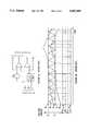
- a triangle wave oscillatorramps at a constant frequency between two potentials applied to terminals B and C to provide a timing ramp that is available at terminal G.
- An error signalis applied at terminal A.
- a comparator having an output terminal Fcompares the oscillator potential against the error signal potential. Its input polarities are configured such that when the error signal potential exceeds the oscillator potential the output is high, and conversely. Terminal F serves as the control terminal for the buck switch S1 of FIG. 1.
- Another comparator having an output terminal Ecompares the oscillator potential against a potential equal to the error signal potential decreased by an amount V LS .
- V LSis ideally equal in magnitude to the difference in the potential across terminals B and C, which is equal to the voltage excursion magnitude of the oscillator.
- Terminal Eserves as the control terminal for the boost switch S2 of FIG. 1.
- a disadvantage in the design of the prior art FA7618 controlleris the implementation of the level shift circuit. The key to optimal transition between buck and boost modes without overlapping lies in precisely tracking the level shift magnitude with the timing ramp magnitude. Therefore, control of the level shift and the timing ramp magnitudes are critical, the former being the more difficult to control precisely.
- FIG. 1is a schematic diagram of a prior art two-switch buck-boost converter.
- FIG. 2Ais a functional block diagram of the prior art FA7618 buck-boost controller that may be employed to control the prior art two-switch buck-boost converter of FIG. 1.
- FIG. 2Bis a waveform diagram illustrating various voltage waveforms that associated with operation of the prior art buck-boost controller of FIG. 2A.
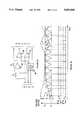
- FIG. 3Ais a functional block diagram of a buck-boost controller in accordance with a first embodiment of the present invention.
- FIG. 3Bis a waveform diagram illustrating various voltage waveforms associated with operation of the buck-boost controller of FIG. 3A.
- FIG. 4Ais a functional block diagram of a buck-boost controller in accordance with a second embodiment of the present invention.
- FIG. 4Bis a waveform diagram illustrating various voltage waveforms associated with operation of the buck-boost controller of FIG. 4A.
- FIGS. 3A-Bthere are shown a buck-boost controller and associated voltage waveform diagrams in accordance with a first embodiment of the present invention in which a triangle-wave oscillator 10 produces a voltage ramp signal (terminal G) at a constant frequency between two voltages that are applied at input terminals B and C.
- the voltage ramp signal produced by oscillator 10may also be referred to as a timing ramp signal.
- An error signalis applied at terminal A.
- a first comparator 12 having an output terminal Fcompares the voltage ramp signal produced by oscillator 10 against the error signal.
- the input polarities of comparator 12are configured such that when the error signal voltage exceeds the voltage ramp signal the output is high, and conversely.
- An output terminal F of comparator 12serves as the control terminal for the buck switch S1 of a conventional buck-boost converter, such as that shown in FIG. 1.
- a second comparator 14 having an output terminal Ecompares the voltage ramp signal produced by oscillator 10 against the output of an operational amplifier 16.
- Operational amplifier 16is configured for negative unity gain of the error signal applied at terminal A.
- a positive input of operational amplifier 16is controlled by the same reference which controls the peak potential voltage (voltage applied at terminal B) of the voltage ramp signal produced by oscillator 10.
- While one-at-a-time buck-boost drive signalsare provided by both the prior art circuit of FIG. 2A and the circuit of applicant's invention described in the preceding paragraph, a significant difference lies in the relationship between the boost drive signal and the voltage ramp signal. While the timing relationship of both buck and boost drive signals with respect to the voltage ramp signal are the same in both circuits in that both the buck and boost drive signals begin at 0% duty cycle at the valley of the voltage ramp signal, the buck drive signal in applicant's circuit begins at 0% duty cycle at the valley of the voltage ramp signal G, but the boost drive signal begins begins at 0% duty cycle at the peak of the voltage ramp signal G.
- the advantages of applicant's buck-boost controller circuit described aboveare the elimination of level shift circuitry and the ramp magnitude tracking requirement.
- FIGS. 4A-Bthere are shown a single-channel buck-boost controller and associated voltage waveform diagrams in accordance with a second embodiment of the present invention in which a triangle-wave oscillator 50 produces a voltage ramp signal (terminal G) between three voltages that are applied at input terminals B, C, and D.
- An error signalis applied at terminal A.
- a first comparator 52 having an output terminal Hcompares the error signal against the voltage applied at terminal C. If the voltage of the error signal is less than the voltage applied at terminal C, the output of comparator 52 will be low, and vice versa.
- comparator 52serves as an input to oscillator 50 such that when the input is low, oscillator 50 will produce a voltage ramp signal at terminal G that ramps between the voltages applied at terminals D and C. When the input to oscillator 50 is high, oscillator 50 will produce a voltage ramp signal that ramps between the voltages applied at terminals C and B.
- the voltages D, C, and Bare in order of increasing voltage and are equally spaced in voltage.
- a second comparator 54having an output terminal that serves as an input to an OR-gate 56 having an output terminal F compares the voltage ramp signal produced by oscillator 50 against the error signal.
- the input polarities of comparator 54are configured such that when the voltage of the error signal exceeds the voltage of the voltage ramp signal produced by oscillator 50, the output of comparator 54 is high, and conversely.
- Terminal Fserves as the control terminal for the buck switch S1 of a conventional buck-boost converter, such as that shown in FIG. 1.
- the output of comparator 52is applied as a second input to OR-gate 56. This signal serves to maintain the buck switch S1 ON continuously when the voltage of the error signal exceeds the voltage applied at terminal C.
- a third comparator 58 having an output terminal that serves as an input to an AND-gate 60 having an output terminal Ecompares the voltage ramp signal produced by oscillator 50 against the error signal.
- the input polarities of comparator 58are configured such that when the voltage of the error signal exceeds the voltage of the voltage ramp signal produced by oscillator 50, the output of comparator 58 is high, and conversely.
- Terminal Eserves as the control terminal for the boost switch S2 of a conventional buck-boost converter, such as that shown in FIG. 1.
- the output of comparator 52is applied as a second input to AND-gate 60 and serves to maintain the boost switch S2 OFF continuously when the voltage applied at terminal C exceeds the voltage of the error signal.
- the second embodiment of his buck-boost controlleralso eliminates the complex level shifting circuitry employed in prior art buck-boost controllers.
Landscapes
- Engineering & Computer Science (AREA)
- Physics & Mathematics (AREA)
- Electromagnetism (AREA)
- General Physics & Mathematics (AREA)
- Radar, Positioning & Navigation (AREA)
- Automation & Control Theory (AREA)
- Power Engineering (AREA)
- Dc-Dc Converters (AREA)
Abstract
Description
Claims (8)
Priority Applications (2)
| Application Number | Priority Date | Filing Date | Title |
|---|---|---|---|
| US08/062,309US5402060A (en) | 1993-05-13 | 1993-05-13 | Controller for two-switch buck-boost converter |
| JP12199094AJP3440314B2 (en) | 1993-05-13 | 1994-05-11 | Buck-boost converter with 2 switches |
Applications Claiming Priority (1)
| Application Number | Priority Date | Filing Date | Title |
|---|---|---|---|
| US08/062,309US5402060A (en) | 1993-05-13 | 1993-05-13 | Controller for two-switch buck-boost converter |
Publications (1)
| Publication Number | Publication Date |
|---|---|
| US5402060Atrue US5402060A (en) | 1995-03-28 |
Family
ID=22041649
Family Applications (1)
| Application Number | Title | Priority Date | Filing Date |
|---|---|---|---|
| US08/062,309Expired - LifetimeUS5402060A (en) | 1993-05-13 | 1993-05-13 | Controller for two-switch buck-boost converter |
Country Status (2)
| Country | Link |
|---|---|
| US (1) | US5402060A (en) |
| JP (1) | JP3440314B2 (en) |
Cited By (125)
| Publication number | Priority date | Publication date | Assignee | Title |
|---|---|---|---|---|
| US5528125A (en)* | 1995-04-05 | 1996-06-18 | Texas Instruments Incorporated | Buck-boost switch mode power supply with burst topology |
| US5602463A (en)* | 1995-12-11 | 1997-02-11 | Lockheed Martin Corporation | DC power supply with enhanced input power factor using a buck and boost converter |
| US5889391A (en)* | 1997-11-07 | 1999-03-30 | Sierra Applied Sciences, Inc. | Power supply having combined regulator and pulsing circuits |
| US5949224A (en)* | 1997-08-06 | 1999-09-07 | Telefonaktiebolaget Lm Ericsson | Buck boost switching regulator |
| US5990668A (en)* | 1997-11-07 | 1999-11-23 | Sierra Applied Sciences, Inc. | A.C. power supply having combined regulator and pulsing circuits |
| WO1999061965A1 (en)* | 1998-05-27 | 1999-12-02 | Maxim Integrated Products, Inc. | Switching power supplies with linear precharge, pseudo-buck and pseudo-boost modes |
| US6037755A (en)* | 1998-07-07 | 2000-03-14 | Lucent Technologies Inc. | Switching controller for a buck+boost converter and method of operation thereof |
| US6058030A (en)* | 1997-11-20 | 2000-05-02 | Intersil Corporation | Multiple output DC-to-DC converter having enhanced noise margin and related methods |
| US6087816A (en)* | 1999-06-29 | 2000-07-11 | Maxim Integrated Products, Inc. | Step-up/step-down switching regulators and pulse width modulation control therefor |
| US6108225A (en)* | 1997-08-26 | 2000-08-22 | Matsushita Electric Works, Ltd. | Power device with commonly used switching elements |
| WO2000067366A1 (en)* | 1999-05-04 | 2000-11-09 | Koninklijke Philips Electronics N.V. | Dc-dc converter |
| WO2000069055A1 (en)* | 1999-05-05 | 2000-11-16 | Siemens Ag Österreich | Dc to dc converter |
| US6342822B1 (en) | 2000-11-28 | 2002-01-29 | Fairchild Semiconductor Corporation | Method and apparatus for implementing improved pulse width modulation |
| US6404172B1 (en)* | 2000-11-20 | 2002-06-11 | Sigmatel, Inc. | Method and apparatus for providing integrated buck or boost conversion |
| US6469482B1 (en) | 2000-06-30 | 2002-10-22 | Intel Corporation | Inductive charge pump circuit for providing voltages useful for flash memory and other applications |
| US6580253B2 (en)* | 2001-08-07 | 2003-06-17 | Seiko Instruments Inc. | Boosting and step-down switching regulator controlling circuit and boosting and step-down switching regulator for use in the same |
| US6731099B2 (en)* | 2001-03-05 | 2004-05-04 | Fujitsu Limited | DC-DC converter with control circuit capable of generating step-up and step-down signals |
| US6734655B1 (en)* | 2000-06-30 | 2004-05-11 | Intel Corporation | Regulator design for inductive booster pump using pulse width modulation technique |
| US6778411B2 (en) | 2002-11-18 | 2004-08-17 | Ballard Power Systems Corporation | Start-up circuit for power converters with controller power supply connected at output side |
| US20040207373A1 (en)* | 2003-01-08 | 2004-10-21 | Siemens Aktiengesellschaft | Low-cost DC-DC voltage switching converter regulator device |
| US20060011595A1 (en)* | 2004-07-13 | 2006-01-19 | Lincoln Global, Inc. | Power source for electric arc welding |
| US20060091867A1 (en)* | 2002-11-15 | 2006-05-04 | Koninklijke Philips Electronics, N.V. | Power converter |
| EP1508960A3 (en)* | 2003-08-11 | 2006-05-31 | Semiconductor Components Industries, LLC | Method of forming a high efficiency power controller |
| US20060175313A1 (en)* | 2005-02-07 | 2006-08-10 | Lincoln Global, Inc | Modular power source for electric ARC welding and output chopper |
| US20060198170A1 (en)* | 2005-03-02 | 2006-09-07 | Fujitsu Limited | DC-DC converter, DC-DC converter control apparatus, power supply apparatus, electronic equipment and control method for DC-DC converter |
| US20060213890A1 (en)* | 2005-03-24 | 2006-09-28 | Lincoln Global, Inc. | Three stage power source for electric ARC welding |
| US20060226130A1 (en)* | 2005-04-08 | 2006-10-12 | Lincoln Global, Inc. | Chopper output stage for arc welder power source |
| US20070051712A1 (en)* | 2004-07-13 | 2007-03-08 | Lincoln Global, Inc. | Three stage power source for electric arc welding |
| EP1804368A1 (en)* | 2005-12-29 | 2007-07-04 | Austriamicrosystems AG | Method for DC/DC conversion and DC/DC converter arrangement |
| DE102006009956A1 (en)* | 2006-03-03 | 2007-09-13 | Texas Instruments Deutschland Gmbh | Up / step-down DC / DC converter |
| US20070210782A1 (en)* | 2006-03-03 | 2007-09-13 | Texas Instruments Deutschland Gmbh | Buck-boost dc/dc converter |
| US20070236977A1 (en)* | 2006-03-24 | 2007-10-11 | Stmicroelectronics S.R.L. | Switching voltage regulator control device |
| US20070290667A1 (en)* | 2006-06-16 | 2007-12-20 | Fujitsu Limited | Step-up/step-down type DC-DC converter, and control circuit and control method of the same |
| US20080136367A1 (en)* | 2006-12-06 | 2008-06-12 | Meir Adest | Battery power delivery module |
| US20080147335A1 (en)* | 2006-12-06 | 2008-06-19 | Meir Adest | Monitoring of distributed power harvesting systems using dc power sources |
| US20080143188A1 (en)* | 2006-12-06 | 2008-06-19 | Meir Adest | Distributed power harvesting systems using dc power sources |
| US20080150366A1 (en)* | 2006-12-06 | 2008-06-26 | Solaredge, Ltd. | Method for distributed power harvesting using dc power sources |
| US20080211474A1 (en)* | 2003-04-28 | 2008-09-04 | Shohichi Nitta | Step-up/down DC-DC converter |
| US20090039852A1 (en)* | 2007-08-06 | 2009-02-12 | Solaredge Technologies Ltd. | Digital average input current control in power converter |
| US20090145480A1 (en)* | 2007-12-05 | 2009-06-11 | Meir Adest | Photovoltaic system power tracking method |
| US20090146667A1 (en)* | 2007-12-05 | 2009-06-11 | Meir Adest | Testing of a photovoltaic panel |
| US20090206666A1 (en)* | 2007-12-04 | 2009-08-20 | Guy Sella | Distributed power harvesting systems using dc power sources |
| EP2096743A1 (en)* | 2008-02-06 | 2009-09-02 | i f m electronic gmbh | Voltage converter |
| US7605498B2 (en) | 2007-10-15 | 2009-10-20 | Ampt, Llc | Systems for highly efficient solar power conversion |
| EP2135348A2 (en) | 2006-12-06 | 2009-12-23 | Solaredge Technologies | Distributed power harvesting systems using dc power sources |
| US20100156368A1 (en)* | 2008-12-19 | 2010-06-24 | Active-Semi, Inc. | Power converters with switched capacitor buck/boost |
| US20100246230A1 (en)* | 2007-10-23 | 2010-09-30 | Ampt, Llc | High reliability power systems and solar power converters |
| CN101895199A (en)* | 2010-07-02 | 2010-11-24 | 华中科技大学 | Isolation type Buck-Boost direct current converter |
| US20100301991A1 (en)* | 2009-05-26 | 2010-12-02 | Guy Sella | Theft detection and prevention in a power generation system |
| US20100309697A1 (en)* | 2009-06-03 | 2010-12-09 | Lincoln Global, Inc. | Input current generating scheme for buck-boost controller |
| US20100308782A1 (en)* | 2009-06-03 | 2010-12-09 | Lincoln Global, Inc. | Controller for a buck-boost circuit |
| US20100320975A1 (en)* | 2009-06-22 | 2010-12-23 | Seagate Technology Llc | Quasi-continuous voltage regulator with dual polarity outputs |
| US20100327833A1 (en)* | 2007-06-26 | 2010-12-30 | Austriamicrosystems Ag | Buck-Boost Switching Regulator and Method Thereof |
| US20110001461A1 (en)* | 2009-07-01 | 2011-01-06 | Richtek Technology Corporation, R.O.C. | Buck-boost switching regulator and control circuit and method therefor |
| US20110084553A1 (en)* | 2007-12-04 | 2011-04-14 | Meir Adest | Distributed power system using direct current power sources |
| US20110121652A1 (en)* | 2006-12-06 | 2011-05-26 | Guy Sella | Pairing of components in a direct current distributed power generation system |
| US20110125431A1 (en)* | 2007-12-05 | 2011-05-26 | Meir Adest | Testing of a Photovoltaic Panel |
| US20110133552A1 (en)* | 2009-12-01 | 2011-06-09 | Yaron Binder | Dual Use Photovoltaic System |
| US20110181264A1 (en)* | 2010-01-26 | 2011-07-28 | Freescale Semiconductor, Inc | Controller for buck and boost converter |
| US20110181340A1 (en)* | 2010-01-27 | 2011-07-28 | Meir Gazit | Fast Voltage Level Shifter Circuit |
| CN101594053B (en)* | 2009-03-27 | 2011-08-17 | 广州金升阳科技有限公司 | Power supply converter with wide-range voltage input |
| US20110199062A1 (en)* | 2007-08-20 | 2011-08-18 | Austriamicrosystems Ag | DC/DC Converter Arrangement and Method for DC/DC Conversion |
| US8289742B2 (en) | 2007-12-05 | 2012-10-16 | Solaredge Ltd. | Parallel connected inverters |
| CN102742135A (en)* | 2010-01-28 | 2012-10-17 | 三美电机株式会社 | Step-up/down DC-DC converter and switching control circuit |
| US8300438B1 (en)* | 2008-11-16 | 2012-10-30 | Edward Herbert | Power factor corrected 3-phase Ac-dc power converter using natural modulation |
| US8384243B2 (en) | 2007-12-04 | 2013-02-26 | Solaredge Technologies Ltd. | Distributed power harvesting systems using DC power sources |
| CN103187874A (en)* | 2011-12-27 | 2013-07-03 | 立锜科技股份有限公司 | Step-up converter with step-down regulation capability and step-down regulation method thereof |
| TWI404309B (en)* | 2010-12-09 | 2013-08-01 | Richtek Technology Corp | Control circuit and method for buck-boost switching converter |
| US8531055B2 (en) | 2006-12-06 | 2013-09-10 | Solaredge Ltd. | Safety mechanisms, wake up and shutdown methods in distributed power installations |
| US8570005B2 (en) | 2011-09-12 | 2013-10-29 | Solaredge Technologies Ltd. | Direct current link circuit |
| US8816535B2 (en) | 2007-10-10 | 2014-08-26 | Solaredge Technologies, Ltd. | System and method for protection during inverter shutdown in distributed power installations |
| US8928302B2 (en) | 2012-09-21 | 2015-01-06 | Kabushiki Kaisha Toshiba | Step-up/down type power supply circuit |
| US8957650B2 (en) | 2010-01-28 | 2015-02-17 | Mitsumi Electric Co., Ltd. | Step-up/down DC-DC converter and switching control circuit |
| US8957645B2 (en) | 2008-03-24 | 2015-02-17 | Solaredge Technologies Ltd. | Zero voltage switching |
| US8988838B2 (en) | 2012-01-30 | 2015-03-24 | Solaredge Technologies Ltd. | Photovoltaic panel circuitry |
| US9000617B2 (en) | 2008-05-05 | 2015-04-07 | Solaredge Technologies, Ltd. | Direct current power combiner |
| US9006569B2 (en) | 2009-05-22 | 2015-04-14 | Solaredge Technologies Ltd. | Electrically isolated heat dissipating junction box |
| US9130401B2 (en) | 2006-12-06 | 2015-09-08 | Solaredge Technologies Ltd. | Distributed power harvesting systems using DC power sources |
| US9235228B2 (en) | 2012-03-05 | 2016-01-12 | Solaredge Technologies Ltd. | Direct current link circuit |
| CN105471264A (en)* | 2015-12-24 | 2016-04-06 | 矽力杰半导体技术(杭州)有限公司 | Control circuit and control method used for four-switch buck-boost converter |
| US9318974B2 (en) | 2014-03-26 | 2016-04-19 | Solaredge Technologies Ltd. | Multi-level inverter with flying capacitor topology |
| US9397497B2 (en) | 2013-03-15 | 2016-07-19 | Ampt, Llc | High efficiency interleaved solar power supply system |
| US9401599B2 (en) | 2010-12-09 | 2016-07-26 | Solaredge Technologies Ltd. | Disconnection of a string carrying direct current power |
| US9442504B2 (en) | 2009-04-17 | 2016-09-13 | Ampt, Llc | Methods and apparatus for adaptive operation of solar power systems |
| US9548619B2 (en) | 2013-03-14 | 2017-01-17 | Solaredge Technologies Ltd. | Method and apparatus for storing and depleting energy |
| EP3136576A2 (en) | 2015-08-07 | 2017-03-01 | MediaTek Inc. | Buck-boost converter and method for controlling buck-boost converter |
| US9647442B2 (en) | 2010-11-09 | 2017-05-09 | Solaredge Technologies Ltd. | Arc detection and prevention in a power generation system |
| EP2367275B1 (en) | 2010-03-18 | 2017-10-25 | ABB Research LTD | Non-isolated DC - DC converter for solar power plant |
| US9812984B2 (en) | 2012-01-30 | 2017-11-07 | Solaredge Technologies Ltd. | Maximizing power in a photovoltaic distributed power system |
| US9819178B2 (en) | 2013-03-15 | 2017-11-14 | Solaredge Technologies Ltd. | Bypass mechanism |
| US9831824B2 (en) | 2007-12-05 | 2017-11-28 | SolareEdge Technologies Ltd. | Current sensing on a MOSFET |
| US9853565B2 (en) | 2012-01-30 | 2017-12-26 | Solaredge Technologies Ltd. | Maximized power in a photovoltaic distributed power system |
| US9855620B2 (en) | 2005-02-07 | 2018-01-02 | Lincoln Global, Inc. | Welding system and method of welding |
| US9866098B2 (en) | 2011-01-12 | 2018-01-09 | Solaredge Technologies Ltd. | Serially connected inverters |
| US9870016B2 (en) | 2012-05-25 | 2018-01-16 | Solaredge Technologies Ltd. | Circuit for interconnected direct current power sources |
| US9941813B2 (en) | 2013-03-14 | 2018-04-10 | Solaredge Technologies Ltd. | High frequency multi-level inverter |
| US10032939B2 (en) | 2009-10-19 | 2018-07-24 | Ampt, Llc | DC power conversion circuit |
| US10061957B2 (en) | 2016-03-03 | 2018-08-28 | Solaredge Technologies Ltd. | Methods for mapping power generation installations |
| US10115841B2 (en) | 2012-06-04 | 2018-10-30 | Solaredge Technologies Ltd. | Integrated photovoltaic panel circuitry |
| US10230310B2 (en) | 2016-04-05 | 2019-03-12 | Solaredge Technologies Ltd | Safety switch for photovoltaic systems |
| US10243463B2 (en) | 2017-06-08 | 2019-03-26 | Texas Instruments Incorporated | Non-inverting buck-boost converter control |
| US10599113B2 (en) | 2016-03-03 | 2020-03-24 | Solaredge Technologies Ltd. | Apparatus and method for determining an order of power devices in power generation systems |
| US10673229B2 (en) | 2010-11-09 | 2020-06-02 | Solaredge Technologies Ltd. | Arc detection and prevention in a power generation system |
| US10673222B2 (en) | 2010-11-09 | 2020-06-02 | Solaredge Technologies Ltd. | Arc detection and prevention in a power generation system |
| US10734980B2 (en) | 2018-05-31 | 2020-08-04 | Fermi Research Alliance, Llc | Pulse charging system |
| US10931119B2 (en) | 2012-01-11 | 2021-02-23 | Solaredge Technologies Ltd. | Photovoltaic module |
| US11018623B2 (en) | 2016-04-05 | 2021-05-25 | Solaredge Technologies Ltd. | Safety switch for photovoltaic systems |
| US11081608B2 (en) | 2016-03-03 | 2021-08-03 | Solaredge Technologies Ltd. | Apparatus and method for determining an order of power devices in power generation systems |
| US11177663B2 (en) | 2016-04-05 | 2021-11-16 | Solaredge Technologies Ltd. | Chain of power devices |
| US11264947B2 (en) | 2007-12-05 | 2022-03-01 | Solaredge Technologies Ltd. | Testing of a photovoltaic panel |
| US11296650B2 (en) | 2006-12-06 | 2022-04-05 | Solaredge Technologies Ltd. | System and method for protection during inverter shutdown in distributed power installations |
| US11303212B2 (en)* | 2014-12-05 | 2022-04-12 | Analog Devices International Unlimited Company | Peak-buck peak-boost current-mode control for switched step-up step-down regulators |
| US11309832B2 (en) | 2006-12-06 | 2022-04-19 | Solaredge Technologies Ltd. | Distributed power harvesting systems using DC power sources |
| US20220209670A1 (en)* | 2020-12-30 | 2022-06-30 | Astec International Limited | Non-inverting buck-boost converter |
| US11418118B1 (en)* | 2019-02-08 | 2022-08-16 | Renesas Electronics America Inc. | Regulation loop control for voltage regulation in a switch mode power supply |
| US11569659B2 (en) | 2006-12-06 | 2023-01-31 | Solaredge Technologies Ltd. | Distributed power harvesting systems using DC power sources |
| US11682972B2 (en) | 2021-02-04 | 2023-06-20 | Analog Devices, Inc. | Peak current mode control for buck-boost regulators |
| US11687112B2 (en) | 2006-12-06 | 2023-06-27 | Solaredge Technologies Ltd. | Distributed power harvesting systems using DC power sources |
| US11728768B2 (en) | 2006-12-06 | 2023-08-15 | Solaredge Technologies Ltd. | Pairing of components in a direct current distributed power generation system |
| US11735910B2 (en) | 2006-12-06 | 2023-08-22 | Solaredge Technologies Ltd. | Distributed power system using direct current power sources |
| US11855231B2 (en) | 2006-12-06 | 2023-12-26 | Solaredge Technologies Ltd. | Distributed power harvesting systems using DC power sources |
| US11881814B2 (en) | 2005-12-05 | 2024-01-23 | Solaredge Technologies Ltd. | Testing of a photovoltaic panel |
| US11888387B2 (en) | 2006-12-06 | 2024-01-30 | Solaredge Technologies Ltd. | Safety mechanisms, wake up and shutdown methods in distributed power installations |
| US12057807B2 (en) | 2016-04-05 | 2024-08-06 | Solaredge Technologies Ltd. | Chain of power devices |
| US12418177B2 (en) | 2009-10-24 | 2025-09-16 | Solaredge Technologies Ltd. | Distributed power system using direct current power sources |
Families Citing this family (2)
| Publication number | Priority date | Publication date | Assignee | Title |
|---|---|---|---|---|
| JP2007151340A (en) | 2005-11-29 | 2007-06-14 | Ricoh Co Ltd | Buck-boost switching regulator |
| JP6487719B2 (en)* | 2015-03-03 | 2019-03-20 | 新日本無線株式会社 | Switching control circuit and switching control method |
Citations (7)
| Publication number | Priority date | Publication date | Assignee | Title |
|---|---|---|---|---|
| US4161771A (en)* | 1977-07-25 | 1979-07-17 | Gulton Industries, Inc. | Inverter ripple regulator |
| US4549254A (en)* | 1983-02-03 | 1985-10-22 | Chrysler Corporation | Buck-boost regulated D.C. to D.C. power supply |
| US4639844A (en)* | 1982-09-13 | 1987-01-27 | Venus Scientific Inc. | Resonant current driven power source for low input voltages |
| US4685040A (en)* | 1985-12-06 | 1987-08-04 | General Electric Company | Integrated circuit for controlling power converter by frequency modulation and pulse width modulation |
| US4686617A (en)* | 1986-06-06 | 1987-08-11 | Rca Corporation | Current limited constant frequency dc converter |
| US4864213A (en)* | 1987-12-11 | 1989-09-05 | Nec Corporation | DC supply having low and high constant voltages for powering a polarity inverter controller |
| US5289361A (en)* | 1991-01-16 | 1994-02-22 | Vlt Corporation | Adaptive boost switching preregulator and method |
- 1993
- 1993-05-13USUS08/062,309patent/US5402060A/ennot_activeExpired - Lifetime
- 1994
- 1994-05-11JPJP12199094Apatent/JP3440314B2/ennot_activeExpired - Lifetime
Patent Citations (7)
| Publication number | Priority date | Publication date | Assignee | Title |
|---|---|---|---|---|
| US4161771A (en)* | 1977-07-25 | 1979-07-17 | Gulton Industries, Inc. | Inverter ripple regulator |
| US4639844A (en)* | 1982-09-13 | 1987-01-27 | Venus Scientific Inc. | Resonant current driven power source for low input voltages |
| US4549254A (en)* | 1983-02-03 | 1985-10-22 | Chrysler Corporation | Buck-boost regulated D.C. to D.C. power supply |
| US4685040A (en)* | 1985-12-06 | 1987-08-04 | General Electric Company | Integrated circuit for controlling power converter by frequency modulation and pulse width modulation |
| US4686617A (en)* | 1986-06-06 | 1987-08-11 | Rca Corporation | Current limited constant frequency dc converter |
| US4864213A (en)* | 1987-12-11 | 1989-09-05 | Nec Corporation | DC supply having low and high constant voltages for powering a polarity inverter controller |
| US5289361A (en)* | 1991-01-16 | 1994-02-22 | Vlt Corporation | Adaptive boost switching preregulator and method |
Cited By (349)
| Publication number | Priority date | Publication date | Assignee | Title |
|---|---|---|---|---|
| US5528125A (en)* | 1995-04-05 | 1996-06-18 | Texas Instruments Incorporated | Buck-boost switch mode power supply with burst topology |
| US5602463A (en)* | 1995-12-11 | 1997-02-11 | Lockheed Martin Corporation | DC power supply with enhanced input power factor using a buck and boost converter |
| US5949224A (en)* | 1997-08-06 | 1999-09-07 | Telefonaktiebolaget Lm Ericsson | Buck boost switching regulator |
| US6108225A (en)* | 1997-08-26 | 2000-08-22 | Matsushita Electric Works, Ltd. | Power device with commonly used switching elements |
| US5889391A (en)* | 1997-11-07 | 1999-03-30 | Sierra Applied Sciences, Inc. | Power supply having combined regulator and pulsing circuits |
| US5990668A (en)* | 1997-11-07 | 1999-11-23 | Sierra Applied Sciences, Inc. | A.C. power supply having combined regulator and pulsing circuits |
| US6058030A (en)* | 1997-11-20 | 2000-05-02 | Intersil Corporation | Multiple output DC-to-DC converter having enhanced noise margin and related methods |
| US5998977A (en)* | 1998-05-27 | 1999-12-07 | Maxim Integrated Products, Inc. | Switching power supplies with linear precharge, pseudo-buck and pseudo-boost modes |
| WO1999061965A1 (en)* | 1998-05-27 | 1999-12-02 | Maxim Integrated Products, Inc. | Switching power supplies with linear precharge, pseudo-buck and pseudo-boost modes |
| US6037755A (en)* | 1998-07-07 | 2000-03-14 | Lucent Technologies Inc. | Switching controller for a buck+boost converter and method of operation thereof |
| WO2000067366A1 (en)* | 1999-05-04 | 2000-11-09 | Koninklijke Philips Electronics N.V. | Dc-dc converter |
| US6191567B1 (en) | 1999-05-04 | 2001-02-20 | U.S. Philips Corporation | DC-DC converter, with duty cycle comparison for a dual mode back boost converter |
| WO2000069055A1 (en)* | 1999-05-05 | 2000-11-16 | Siemens Ag Österreich | Dc to dc converter |
| US6087816A (en)* | 1999-06-29 | 2000-07-11 | Maxim Integrated Products, Inc. | Step-up/step-down switching regulators and pulse width modulation control therefor |
| US6734655B1 (en)* | 2000-06-30 | 2004-05-11 | Intel Corporation | Regulator design for inductive booster pump using pulse width modulation technique |
| US6469482B1 (en) | 2000-06-30 | 2002-10-22 | Intel Corporation | Inductive charge pump circuit for providing voltages useful for flash memory and other applications |
| US6404172B1 (en)* | 2000-11-20 | 2002-06-11 | Sigmatel, Inc. | Method and apparatus for providing integrated buck or boost conversion |
| US6342822B1 (en) | 2000-11-28 | 2002-01-29 | Fairchild Semiconductor Corporation | Method and apparatus for implementing improved pulse width modulation |
| US6731099B2 (en)* | 2001-03-05 | 2004-05-04 | Fujitsu Limited | DC-DC converter with control circuit capable of generating step-up and step-down signals |
| US6580253B2 (en)* | 2001-08-07 | 2003-06-17 | Seiko Instruments Inc. | Boosting and step-down switching regulator controlling circuit and boosting and step-down switching regulator for use in the same |
| US7839132B2 (en)* | 2002-11-15 | 2010-11-23 | Nxp B.V. | Power converter |
| US20060091867A1 (en)* | 2002-11-15 | 2006-05-04 | Koninklijke Philips Electronics, N.V. | Power converter |
| US6778411B2 (en) | 2002-11-18 | 2004-08-17 | Ballard Power Systems Corporation | Start-up circuit for power converters with controller power supply connected at output side |
| US20040207373A1 (en)* | 2003-01-08 | 2004-10-21 | Siemens Aktiengesellschaft | Low-cost DC-DC voltage switching converter regulator device |
| US7242168B2 (en)* | 2003-01-08 | 2007-07-10 | Siemens Aktiengesellschaft | Wide input range buck/boost switching regulator |
| US7570034B2 (en)* | 2003-04-28 | 2009-08-04 | Ricoh Company, Ltd. | Step-up/down DC-DC converter |
| US20080211474A1 (en)* | 2003-04-28 | 2008-09-04 | Shohichi Nitta | Step-up/down DC-DC converter |
| EP1508960A3 (en)* | 2003-08-11 | 2006-05-31 | Semiconductor Components Industries, LLC | Method of forming a high efficiency power controller |
| US9751150B2 (en) | 2004-07-13 | 2017-09-05 | Lincoln Global, Inc. | Power source for electric arc welding |
| US20060011595A1 (en)* | 2004-07-13 | 2006-01-19 | Lincoln Global, Inc. | Power source for electric arc welding |
| US8269141B2 (en) | 2004-07-13 | 2012-09-18 | Lincoln Global, Inc. | Power source for electric arc welding |
| US20070051712A1 (en)* | 2004-07-13 | 2007-03-08 | Lincoln Global, Inc. | Three stage power source for electric arc welding |
| US8785816B2 (en) | 2004-07-13 | 2014-07-22 | Lincoln Global, Inc. | Three stage power source for electric arc welding |
| US9956639B2 (en) | 2005-02-07 | 2018-05-01 | Lincoln Global, Inc | Modular power source for electric ARC welding and output chopper |
| US20060175313A1 (en)* | 2005-02-07 | 2006-08-10 | Lincoln Global, Inc | Modular power source for electric ARC welding and output chopper |
| US9855620B2 (en) | 2005-02-07 | 2018-01-02 | Lincoln Global, Inc. | Welding system and method of welding |
| US7443147B2 (en)* | 2005-03-02 | 2008-10-28 | Fujitsu Limited | DC-DC converter with step-up and step-down control capable of varying the offset voltage of the PWM triangle |
| US20060198170A1 (en)* | 2005-03-02 | 2006-09-07 | Fujitsu Limited | DC-DC converter, DC-DC converter control apparatus, power supply apparatus, electronic equipment and control method for DC-DC converter |
| US20060213890A1 (en)* | 2005-03-24 | 2006-09-28 | Lincoln Global, Inc. | Three stage power source for electric ARC welding |
| US8581147B2 (en) | 2005-03-24 | 2013-11-12 | Lincoln Global, Inc. | Three stage power source for electric ARC welding |
| US20060226130A1 (en)* | 2005-04-08 | 2006-10-12 | Lincoln Global, Inc. | Chopper output stage for arc welder power source |
| US9647555B2 (en) | 2005-04-08 | 2017-05-09 | Lincoln Global, Inc. | Chopper output stage for arc welder power source |
| US11881814B2 (en) | 2005-12-05 | 2024-01-23 | Solaredge Technologies Ltd. | Testing of a photovoltaic panel |
| US8269471B2 (en) | 2005-12-29 | 2012-09-18 | Austriamicrosystems Ag | Method for DC/DC conversion and DC/DC converter arrangement including four switching phases |
| US20090251122A1 (en)* | 2005-12-29 | 2009-10-08 | Pramod Singnurkar | Method for DC/DC Conversion and DC/DC Converter Arrangement |
| WO2007073940A1 (en)* | 2005-12-29 | 2007-07-05 | Austriamicrosystems Ag | Method for dc/dc conversion and dc/dc converter arrangement |
| EP1804368A1 (en)* | 2005-12-29 | 2007-07-04 | Austriamicrosystems AG | Method for DC/DC conversion and DC/DC converter arrangement |
| DE102006009956B4 (en)* | 2006-03-03 | 2008-05-29 | Texas Instruments Deutschland Gmbh | Up / step-down DC / DC converter |
| US7518346B2 (en) | 2006-03-03 | 2009-04-14 | Texas Instruments Deutschland Gmbh | Buck-boost DC/DC converter with overlap control using ramp shift signal |
| US20070210782A1 (en)* | 2006-03-03 | 2007-09-13 | Texas Instruments Deutschland Gmbh | Buck-boost dc/dc converter |
| DE102006009956A1 (en)* | 2006-03-03 | 2007-09-13 | Texas Instruments Deutschland Gmbh | Up / step-down DC / DC converter |
| US7723966B2 (en)* | 2006-03-24 | 2010-05-25 | Stmicroelectronics, S.R.L. | Switching voltage regulator control device |
| US20070236977A1 (en)* | 2006-03-24 | 2007-10-11 | Stmicroelectronics S.R.L. | Switching voltage regulator control device |
| US20070290667A1 (en)* | 2006-06-16 | 2007-12-20 | Fujitsu Limited | Step-up/step-down type DC-DC converter, and control circuit and control method of the same |
| US7956586B2 (en) | 2006-06-16 | 2011-06-07 | Fujitsu Semiconductor Limited | Step-up/step-down type DC-DC converter, and control circuit and control method of the same |
| US11579235B2 (en) | 2006-12-06 | 2023-02-14 | Solaredge Technologies Ltd. | Safety mechanisms, wake up and shutdown methods in distributed power installations |
| US11682918B2 (en) | 2006-12-06 | 2023-06-20 | Solaredge Technologies Ltd. | Battery power delivery module |
| US10673253B2 (en) | 2006-12-06 | 2020-06-02 | Solaredge Technologies Ltd. | Battery power delivery module |
| US11476799B2 (en) | 2006-12-06 | 2022-10-18 | Solaredge Technologies Ltd. | Distributed power harvesting systems using DC power sources |
| US10637393B2 (en) | 2006-12-06 | 2020-04-28 | Solaredge Technologies Ltd. | Distributed power harvesting systems using DC power sources |
| US9368964B2 (en) | 2006-12-06 | 2016-06-14 | Solaredge Technologies Ltd. | Distributed power system using direct current power sources |
| US11296650B2 (en) | 2006-12-06 | 2022-04-05 | Solaredge Technologies Ltd. | System and method for protection during inverter shutdown in distributed power installations |
| US11569659B2 (en) | 2006-12-06 | 2023-01-31 | Solaredge Technologies Ltd. | Distributed power harvesting systems using DC power sources |
| US11569660B2 (en) | 2006-12-06 | 2023-01-31 | Solaredge Technologies Ltd. | Distributed power harvesting systems using DC power sources |
| US12027849B2 (en) | 2006-12-06 | 2024-07-02 | Solaredge Technologies Ltd. | Distributed power system using direct current power sources |
| US10447150B2 (en) | 2006-12-06 | 2019-10-15 | Solaredge Technologies Ltd. | Distributed power harvesting systems using DC power sources |
| US11575261B2 (en) | 2006-12-06 | 2023-02-07 | Solaredge Technologies Ltd. | Distributed power harvesting systems using DC power sources |
| US11575260B2 (en) | 2006-12-06 | 2023-02-07 | Solaredge Technologies Ltd. | Distributed power harvesting systems using DC power sources |
| US12027970B2 (en) | 2006-12-06 | 2024-07-02 | Solaredge Technologies Ltd. | Safety mechanisms, wake up and shutdown methods in distributed power installations |
| US9543889B2 (en) | 2006-12-06 | 2017-01-10 | Solaredge Technologies Ltd. | Distributed power harvesting systems using DC power sources |
| US11594882B2 (en) | 2006-12-06 | 2023-02-28 | Solaredge Technologies Ltd. | Distributed power harvesting systems using DC power sources |
| US10230245B2 (en) | 2006-12-06 | 2019-03-12 | Solaredge Technologies Ltd | Battery power delivery module |
| US12032080B2 (en) | 2006-12-06 | 2024-07-09 | Solaredge Technologies Ltd. | Safety mechanisms, wake up and shutdown methods in distributed power installations |
| US20110121652A1 (en)* | 2006-12-06 | 2011-05-26 | Guy Sella | Pairing of components in a direct current distributed power generation system |
| US11594881B2 (en) | 2006-12-06 | 2023-02-28 | Solaredge Technologies Ltd. | Distributed power harvesting systems using DC power sources |
| EP2135348A2 (en) | 2006-12-06 | 2009-12-23 | Solaredge Technologies | Distributed power harvesting systems using dc power sources |
| US9130401B2 (en) | 2006-12-06 | 2015-09-08 | Solaredge Technologies Ltd. | Distributed power harvesting systems using DC power sources |
| US10097007B2 (en) | 2006-12-06 | 2018-10-09 | Solaredge Technologies Ltd. | Method for distributed power harvesting using DC power sources |
| US12388492B2 (en) | 2006-12-06 | 2025-08-12 | Solaredge Technologies Ltd. | Safety mechanisms, wake up and shutdown methods in distributed power installations |
| US11594880B2 (en) | 2006-12-06 | 2023-02-28 | Solaredge Technologies Ltd. | Distributed power harvesting systems using DC power sources |
| US11598652B2 (en) | 2006-12-06 | 2023-03-07 | Solaredge Technologies Ltd. | Monitoring of distributed power harvesting systems using DC power sources |
| US9112379B2 (en) | 2006-12-06 | 2015-08-18 | Solaredge Technologies Ltd. | Pairing of components in a direct current distributed power generation system |
| US8013472B2 (en) | 2006-12-06 | 2011-09-06 | Solaredge, Ltd. | Method for distributed power harvesting using DC power sources |
| US9088178B2 (en) | 2006-12-06 | 2015-07-21 | Solaredge Technologies Ltd | Distributed power harvesting systems using DC power sources |
| US11658482B2 (en) | 2006-12-06 | 2023-05-23 | Solaredge Technologies Ltd. | Distributed power harvesting systems using DC power sources |
| US12046940B2 (en) | 2006-12-06 | 2024-07-23 | Solaredge Technologies Ltd. | Battery power control |
| US9966766B2 (en) | 2006-12-06 | 2018-05-08 | Solaredge Technologies Ltd. | Battery power delivery module |
| US11183922B2 (en) | 2006-12-06 | 2021-11-23 | Solaredge Technologies Ltd. | Distributed power harvesting systems using DC power sources |
| US11073543B2 (en) | 2006-12-06 | 2021-07-27 | Solaredge Technologies Ltd. | Monitoring of distributed power harvesting systems using DC power sources |
| US11002774B2 (en) | 2006-12-06 | 2021-05-11 | Solaredge Technologies Ltd. | Monitoring of distributed power harvesting systems using DC power sources |
| US9960731B2 (en) | 2006-12-06 | 2018-05-01 | Solaredge Technologies Ltd. | Pairing of components in a direct current distributed power generation system |
| US12316274B2 (en) | 2006-12-06 | 2025-05-27 | Solaredge Technologies Ltd. | Pairing of components in a direct current distributed power generation system |
| US9960667B2 (en) | 2006-12-06 | 2018-05-01 | Solaredge Technologies Ltd. | System and method for protection during inverter shutdown in distributed power installations |
| US9948233B2 (en) | 2006-12-06 | 2018-04-17 | Solaredge Technologies Ltd. | Distributed power harvesting systems using DC power sources |
| US9041339B2 (en) | 2006-12-06 | 2015-05-26 | Solaredge Technologies Ltd. | Battery power delivery module |
| US8319471B2 (en) | 2006-12-06 | 2012-11-27 | Solaredge, Ltd. | Battery power delivery module |
| US11309832B2 (en) | 2006-12-06 | 2022-04-19 | Solaredge Technologies Ltd. | Distributed power harvesting systems using DC power sources |
| US11687112B2 (en) | 2006-12-06 | 2023-06-27 | Solaredge Technologies Ltd. | Distributed power harvesting systems using DC power sources |
| US11031861B2 (en) | 2006-12-06 | 2021-06-08 | Solaredge Technologies Ltd. | System and method for protection during inverter shutdown in distributed power installations |
| US11728768B2 (en) | 2006-12-06 | 2023-08-15 | Solaredge Technologies Ltd. | Pairing of components in a direct current distributed power generation system |
| US11043820B2 (en) | 2006-12-06 | 2021-06-22 | Solaredge Technologies Ltd. | Battery power delivery module |
| US9853490B2 (en) | 2006-12-06 | 2017-12-26 | Solaredge Technologies Ltd. | Distributed power system using direct current power sources |
| US8473250B2 (en) | 2006-12-06 | 2013-06-25 | Solaredge, Ltd. | Monitoring of distributed power harvesting systems using DC power sources |
| US12281919B2 (en) | 2006-12-06 | 2025-04-22 | Solaredge Technologies Ltd. | Monitoring of distributed power harvesting systems using DC power sources |
| US12276997B2 (en) | 2006-12-06 | 2025-04-15 | Solaredge Technologies Ltd. | Distributed power harvesting systems using DC power sources |
| US11735910B2 (en) | 2006-12-06 | 2023-08-22 | Solaredge Technologies Ltd. | Distributed power system using direct current power sources |
| US8531055B2 (en) | 2006-12-06 | 2013-09-10 | Solaredge Ltd. | Safety mechanisms, wake up and shutdown methods in distributed power installations |
| US12224706B2 (en) | 2006-12-06 | 2025-02-11 | Solaredge Technologies Ltd. | Pairing of components in a direct current distributed power generation system |
| US11962243B2 (en) | 2006-12-06 | 2024-04-16 | Solaredge Technologies Ltd. | Method for distributed power harvesting using DC power sources |
| US8587151B2 (en) | 2006-12-06 | 2013-11-19 | Solaredge, Ltd. | Method for distributed power harvesting using DC power sources |
| US11855231B2 (en) | 2006-12-06 | 2023-12-26 | Solaredge Technologies Ltd. | Distributed power harvesting systems using DC power sources |
| US20080150366A1 (en)* | 2006-12-06 | 2008-06-26 | Solaredge, Ltd. | Method for distributed power harvesting using dc power sources |
| US8659188B2 (en) | 2006-12-06 | 2014-02-25 | Solaredge Technologies Ltd. | Distributed power harvesting systems using DC power sources |
| US20080143188A1 (en)* | 2006-12-06 | 2008-06-19 | Meir Adest | Distributed power harvesting systems using dc power sources |
| US9680304B2 (en) | 2006-12-06 | 2017-06-13 | Solaredge Technologies Ltd. | Method for distributed power harvesting using DC power sources |
| US11961922B2 (en) | 2006-12-06 | 2024-04-16 | Solaredge Technologies Ltd. | Distributed power harvesting systems using DC power sources |
| US20080147335A1 (en)* | 2006-12-06 | 2008-06-19 | Meir Adest | Monitoring of distributed power harvesting systems using dc power sources |
| US11063440B2 (en) | 2006-12-06 | 2021-07-13 | Solaredge Technologies Ltd. | Method for distributed power harvesting using DC power sources |
| US12107417B2 (en) | 2006-12-06 | 2024-10-01 | Solaredge Technologies Ltd. | Distributed power harvesting systems using DC power sources |
| US9590526B2 (en) | 2006-12-06 | 2017-03-07 | Solaredge Technologies Ltd. | Safety mechanisms, wake up and shutdown methods in distributed power installations |
| US20080136367A1 (en)* | 2006-12-06 | 2008-06-12 | Meir Adest | Battery power delivery module |
| US11888387B2 (en) | 2006-12-06 | 2024-01-30 | Solaredge Technologies Ltd. | Safety mechanisms, wake up and shutdown methods in distributed power installations |
| US9644993B2 (en) | 2006-12-06 | 2017-05-09 | Solaredge Technologies Ltd. | Monitoring of distributed power harvesting systems using DC power sources |
| US12068599B2 (en) | 2006-12-06 | 2024-08-20 | Solaredge Technologies Ltd. | System and method for protection during inverter shutdown in distributed power installations |
| US20100253150A1 (en)* | 2007-02-15 | 2010-10-07 | Ampt, Llc | AC Power Systems for Renewable Electrical Energy |
| US8093756B2 (en) | 2007-02-15 | 2012-01-10 | Ampt, Llc | AC power systems for renewable electrical energy |
| US8179113B2 (en) | 2007-06-26 | 2012-05-15 | Austriamicrosystems Ag | Buck-Boost switching regulator and method thereof for DC/DC conversion |
| US20100327833A1 (en)* | 2007-06-26 | 2010-12-30 | Austriamicrosystems Ag | Buck-Boost Switching Regulator and Method Thereof |
| US10116217B2 (en) | 2007-08-06 | 2018-10-30 | Solaredge Technologies Ltd. | Digital average input current control in power converter |
| US8319483B2 (en) | 2007-08-06 | 2012-11-27 | Solaredge Technologies Ltd. | Digital average input current control in power converter |
| US11594968B2 (en) | 2007-08-06 | 2023-02-28 | Solaredge Technologies Ltd. | Digital average input current control in power converter |
| US9673711B2 (en) | 2007-08-06 | 2017-06-06 | Solaredge Technologies Ltd. | Digital average input current control in power converter |
| US20090039852A1 (en)* | 2007-08-06 | 2009-02-12 | Solaredge Technologies Ltd. | Digital average input current control in power converter |
| US10516336B2 (en) | 2007-08-06 | 2019-12-24 | Solaredge Technologies Ltd. | Digital average input current control in power converter |
| US8773092B2 (en) | 2007-08-06 | 2014-07-08 | Solaredge Technologies Ltd. | Digital average input current control in power converter |
| US9035638B2 (en) | 2007-08-20 | 2015-05-19 | Ams Ag | DC/DC converter arrangement and method for DC/DC conversion |
| US20110199062A1 (en)* | 2007-08-20 | 2011-08-18 | Austriamicrosystems Ag | DC/DC Converter Arrangement and Method for DC/DC Conversion |
| US8816535B2 (en) | 2007-10-10 | 2014-08-26 | Solaredge Technologies, Ltd. | System and method for protection during inverter shutdown in distributed power installations |
| US10326283B2 (en) | 2007-10-15 | 2019-06-18 | Ampt, Llc | Converter intuitive photovoltaic electrical energy power system |
| US12003110B2 (en) | 2007-10-15 | 2024-06-04 | Ampt, Llc | Optimized conversion system |
| US12027869B2 (en) | 2007-10-15 | 2024-07-02 | Ampt, Llc | Optimized photovoltaic conversion configuration |
| US12027867B2 (en) | 2007-10-15 | 2024-07-02 | Ampt, Llc | Coordinated converter reactively altering disabling photovoltaic electrical energy power system |
| US11070062B2 (en) | 2007-10-15 | 2021-07-20 | Ampt, Llc | Photovoltaic conversion systems |
| US7605498B2 (en) | 2007-10-15 | 2009-10-20 | Ampt, Llc | Systems for highly efficient solar power conversion |
| US10886746B1 (en) | 2007-10-15 | 2021-01-05 | Ampt, Llc | Alternating conversion solar power system |
| US11228182B2 (en) | 2007-10-15 | 2022-01-18 | Ampt, Llc | Converter disabling photovoltaic electrical energy power system |
| US11289917B1 (en) | 2007-10-15 | 2022-03-29 | Ampt, Llc | Optimized photovoltaic conversion system |
| US9673630B2 (en) | 2007-10-15 | 2017-06-06 | Ampt, Llc | Protected conversion solar power system |
| US7719140B2 (en) | 2007-10-15 | 2010-05-18 | Ampt, Llc | Systems for boundary controlled solar power conversion |
| US10608437B2 (en) | 2007-10-15 | 2020-03-31 | Ampt, Llc | Feedback based photovoltaic conversion systems |
| US11070063B2 (en) | 2007-10-15 | 2021-07-20 | Ampt, Llc | Method for alternating conversion solar power |
| US8242634B2 (en) | 2007-10-15 | 2012-08-14 | Ampt, Llc | High efficiency remotely controllable solar energy system |
| US20100229915A1 (en)* | 2007-10-15 | 2010-09-16 | Ampt, Llc | Systems for Highly Efficient Solar Power |
| US7843085B2 (en) | 2007-10-15 | 2010-11-30 | Ampt, Llc | Systems for highly efficient solar power |
| US20100308662A1 (en)* | 2007-10-15 | 2010-12-09 | Ampt, Llc | High Efficiency Remotely Controllable Solar Energy System |
| US7919953B2 (en) | 2007-10-23 | 2011-04-05 | Ampt, Llc | Solar power capacitor alternative switch circuitry system for enhanced capacitor life |
| US20100246230A1 (en)* | 2007-10-23 | 2010-09-30 | Ampt, Llc | High reliability power systems and solar power converters |
| US20110181251A1 (en)* | 2007-10-23 | 2011-07-28 | Ampt, Llc | Alternative Switch Power Circuitry Systems |
| US8461811B2 (en) | 2007-10-23 | 2013-06-11 | Ampt, Llc | Power capacitor alternative switch circuitry system for enhanced capacitor life |
| US9853538B2 (en) | 2007-12-04 | 2017-12-26 | Solaredge Technologies Ltd. | Distributed power harvesting systems using DC power sources |
| US20110084553A1 (en)* | 2007-12-04 | 2011-04-14 | Meir Adest | Distributed power system using direct current power sources |
| US8384243B2 (en) | 2007-12-04 | 2013-02-26 | Solaredge Technologies Ltd. | Distributed power harvesting systems using DC power sources |
| US8618692B2 (en) | 2007-12-04 | 2013-12-31 | Solaredge Technologies Ltd. | Distributed power system using direct current power sources |
| US8963369B2 (en) | 2007-12-04 | 2015-02-24 | Solaredge Technologies Ltd. | Distributed power harvesting systems using DC power sources |
| US20090206666A1 (en)* | 2007-12-04 | 2009-08-20 | Guy Sella | Distributed power harvesting systems using dc power sources |
| US8599588B2 (en) | 2007-12-05 | 2013-12-03 | Solaredge Ltd. | Parallel connected inverters |
| US20110125431A1 (en)* | 2007-12-05 | 2011-05-26 | Meir Adest | Testing of a Photovoltaic Panel |
| US20090145480A1 (en)* | 2007-12-05 | 2009-06-11 | Meir Adest | Photovoltaic system power tracking method |
| US9831824B2 (en) | 2007-12-05 | 2017-11-28 | SolareEdge Technologies Ltd. | Current sensing on a MOSFET |
| US20090146667A1 (en)* | 2007-12-05 | 2009-06-11 | Meir Adest | Testing of a photovoltaic panel |
| US11894806B2 (en) | 2007-12-05 | 2024-02-06 | Solaredge Technologies Ltd. | Testing of a photovoltaic panel |
| US9291696B2 (en) | 2007-12-05 | 2016-03-22 | Solaredge Technologies Ltd. | Photovoltaic system power tracking method |
| US12055647B2 (en) | 2007-12-05 | 2024-08-06 | Solaredge Technologies Ltd. | Parallel connected inverters |
| US10644589B2 (en) | 2007-12-05 | 2020-05-05 | Solaredge Technologies Ltd. | Parallel connected inverters |
| US9979280B2 (en) | 2007-12-05 | 2018-05-22 | Solaredge Technologies Ltd. | Parallel connected inverters |
| US11693080B2 (en) | 2007-12-05 | 2023-07-04 | Solaredge Technologies Ltd. | Parallel connected inverters |
| US8324921B2 (en) | 2007-12-05 | 2012-12-04 | Solaredge Technologies Ltd. | Testing of a photovoltaic panel |
| US9407161B2 (en) | 2007-12-05 | 2016-08-02 | Solaredge Technologies Ltd. | Parallel connected inverters |
| US10693415B2 (en) | 2007-12-05 | 2020-06-23 | Solaredge Technologies Ltd. | Testing of a photovoltaic panel |
| US11183923B2 (en) | 2007-12-05 | 2021-11-23 | Solaredge Technologies Ltd. | Parallel connected inverters |
| US8289742B2 (en) | 2007-12-05 | 2012-10-16 | Solaredge Ltd. | Parallel connected inverters |
| US11183969B2 (en) | 2007-12-05 | 2021-11-23 | Solaredge Technologies Ltd. | Testing of a photovoltaic panel |
| US11264947B2 (en) | 2007-12-05 | 2022-03-01 | Solaredge Technologies Ltd. | Testing of a photovoltaic panel |
| EP2096743A1 (en)* | 2008-02-06 | 2009-09-02 | i f m electronic gmbh | Voltage converter |
| US9876430B2 (en) | 2008-03-24 | 2018-01-23 | Solaredge Technologies Ltd. | Zero voltage switching |
| US8957645B2 (en) | 2008-03-24 | 2015-02-17 | Solaredge Technologies Ltd. | Zero voltage switching |
| US10468878B2 (en) | 2008-05-05 | 2019-11-05 | Solaredge Technologies Ltd. | Direct current power combiner |
| US9362743B2 (en) | 2008-05-05 | 2016-06-07 | Solaredge Technologies Ltd. | Direct current power combiner |
| US11424616B2 (en) | 2008-05-05 | 2022-08-23 | Solaredge Technologies Ltd. | Direct current power combiner |
| US12218498B2 (en) | 2008-05-05 | 2025-02-04 | Solaredge Technologies Ltd. | Direct current power combiner |
| US9000617B2 (en) | 2008-05-05 | 2015-04-07 | Solaredge Technologies, Ltd. | Direct current power combiner |
| US8300438B1 (en)* | 2008-11-16 | 2012-10-30 | Edward Herbert | Power factor corrected 3-phase Ac-dc power converter using natural modulation |
| US9537445B2 (en) | 2008-12-04 | 2017-01-03 | Solaredge Technologies Ltd. | Testing of a photovoltaic panel |
| US10461687B2 (en) | 2008-12-04 | 2019-10-29 | Solaredge Technologies Ltd. | Testing of a photovoltaic panel |
| US20100156368A1 (en)* | 2008-12-19 | 2010-06-24 | Active-Semi, Inc. | Power converters with switched capacitor buck/boost |
| US7795761B2 (en) | 2008-12-19 | 2010-09-14 | Active-Semi, Inc. | Power converters with switched capacitor buck/boost |
| CN101594053B (en)* | 2009-03-27 | 2011-08-17 | 广州金升阳科技有限公司 | Power supply converter with wide-range voltage input |
| US10938219B2 (en) | 2009-04-17 | 2021-03-02 | Ampt, Llc | Dynamic methods and apparatus for adaptive operation of solar power systems |
| US10326282B2 (en) | 2009-04-17 | 2019-06-18 | Ampt, Llc | Safety methods and apparatus for adaptive operation of solar power systems |
| US9442504B2 (en) | 2009-04-17 | 2016-09-13 | Ampt, Llc | Methods and apparatus for adaptive operation of solar power systems |
| US10686402B2 (en) | 2009-05-22 | 2020-06-16 | Solaredge Technologies Ltd. | Electrically isolated heat dissipating junction box |
| US11695371B2 (en) | 2009-05-22 | 2023-07-04 | Solaredge Technologies Ltd. | Electrically isolated heat dissipating junction box |
| US10411644B2 (en) | 2009-05-22 | 2019-09-10 | Solaredge Technologies, Ltd. | Electrically isolated heat dissipating junction box |
| US9006569B2 (en) | 2009-05-22 | 2015-04-14 | Solaredge Technologies Ltd. | Electrically isolated heat dissipating junction box |
| US9748896B2 (en) | 2009-05-22 | 2017-08-29 | Solaredge Technologies Ltd. | Electrically isolated heat dissipating junction box |
| US10879840B2 (en) | 2009-05-22 | 2020-12-29 | Solaredge Technologies Ltd. | Electrically isolated heat dissipating junction box |
| US9748897B2 (en) | 2009-05-22 | 2017-08-29 | Solaredge Technologies Ltd. | Electrically isolated heat dissipating junction box |
| US12074566B2 (en) | 2009-05-22 | 2024-08-27 | Solaredge Technologies Ltd. | Electrically isolated heat dissipating junction box |
| US11509263B2 (en) | 2009-05-22 | 2022-11-22 | Solaredge Technologies Ltd. | Electrically isolated heat dissipating junction box |
| US9869701B2 (en) | 2009-05-26 | 2018-01-16 | Solaredge Technologies Ltd. | Theft detection and prevention in a power generation system |
| US8947194B2 (en) | 2009-05-26 | 2015-02-03 | Solaredge Technologies Ltd. | Theft detection and prevention in a power generation system |
| US10969412B2 (en) | 2009-05-26 | 2021-04-06 | Solaredge Technologies Ltd. | Theft detection and prevention in a power generation system |
| US11867729B2 (en) | 2009-05-26 | 2024-01-09 | Solaredge Technologies Ltd. | Theft detection and prevention in a power generation system |
| US12306215B2 (en) | 2009-05-26 | 2025-05-20 | Solaredge Technologies Ltd. | Theft detection and prevention in a power generation system |
| US20100301991A1 (en)* | 2009-05-26 | 2010-12-02 | Guy Sella | Theft detection and prevention in a power generation system |
| US20100308782A1 (en)* | 2009-06-03 | 2010-12-09 | Lincoln Global, Inc. | Controller for a buck-boost circuit |
| US8354827B2 (en) | 2009-06-03 | 2013-01-15 | Lincoln Global, Inc. | Controller for a buck-boost circuit |
| US8525495B2 (en) | 2009-06-03 | 2013-09-03 | Lincoln Global, Inc. | Input current generator for buck-boost circuit control |
| US20100309697A1 (en)* | 2009-06-03 | 2010-12-09 | Lincoln Global, Inc. | Input current generating scheme for buck-boost controller |
| US20100320975A1 (en)* | 2009-06-22 | 2010-12-23 | Seagate Technology Llc | Quasi-continuous voltage regulator with dual polarity outputs |
| US8159202B2 (en)* | 2009-06-22 | 2012-04-17 | Seagate Technology Llc | Quasi-continuous voltage regulator with dual polarity outputs |
| US8294439B2 (en)* | 2009-07-01 | 2012-10-23 | Richtek Technology Corporation | Buck-boost switching regulator and control circuit and method therefor |
| US20110001461A1 (en)* | 2009-07-01 | 2011-01-06 | Richtek Technology Corporation, R.O.C. | Buck-boost switching regulator and control circuit and method therefor |
| US11411126B2 (en) | 2009-10-19 | 2022-08-09 | Ampt, Llc | DC power conversion circuit |
| US10032939B2 (en) | 2009-10-19 | 2018-07-24 | Ampt, Llc | DC power conversion circuit |
| US10714637B2 (en) | 2009-10-19 | 2020-07-14 | Ampt, Llc | DC power conversion circuit |
| US12034087B2 (en) | 2009-10-19 | 2024-07-09 | Ampt, Llc | Solar panel power conversion circuit |
| US12418177B2 (en) | 2009-10-24 | 2025-09-16 | Solaredge Technologies Ltd. | Distributed power system using direct current power sources |
| US12316158B2 (en) | 2009-12-01 | 2025-05-27 | Solaredge Technologies Ltd. | Dual use photovoltaic system |
| US20110133552A1 (en)* | 2009-12-01 | 2011-06-09 | Yaron Binder | Dual Use Photovoltaic System |
| US9276410B2 (en) | 2009-12-01 | 2016-03-01 | Solaredge Technologies Ltd. | Dual use photovoltaic system |
| US10270255B2 (en) | 2009-12-01 | 2019-04-23 | Solaredge Technologies Ltd | Dual use photovoltaic system |
| US8710699B2 (en) | 2009-12-01 | 2014-04-29 | Solaredge Technologies Ltd. | Dual use photovoltaic system |
| US11735951B2 (en) | 2009-12-01 | 2023-08-22 | Solaredge Technologies Ltd. | Dual use photovoltaic system |
| US11056889B2 (en) | 2009-12-01 | 2021-07-06 | Solaredge Technologies Ltd. | Dual use photovoltaic system |
| US20110181264A1 (en)* | 2010-01-26 | 2011-07-28 | Freescale Semiconductor, Inc | Controller for buck and boost converter |
| US8410763B2 (en) | 2010-01-26 | 2013-04-02 | Freescale Semiconductor, Inc. | Controller for buck and boost converter |
| US9917587B2 (en) | 2010-01-27 | 2018-03-13 | Solaredge Technologies Ltd. | Fast voltage level shifter circuit |
| US9564882B2 (en) | 2010-01-27 | 2017-02-07 | Solaredge Technologies Ltd. | Fast voltage level shifter circuit |
| US20110181340A1 (en)* | 2010-01-27 | 2011-07-28 | Meir Gazit | Fast Voltage Level Shifter Circuit |
| US9231570B2 (en) | 2010-01-27 | 2016-01-05 | Solaredge Technologies Ltd. | Fast voltage level shifter circuit |
| US8766696B2 (en) | 2010-01-27 | 2014-07-01 | Solaredge Technologies Ltd. | Fast voltage level shifter circuit |
| US9048729B2 (en)* | 2010-01-28 | 2015-06-02 | Mitsumi Electric Co., Ltd. | Step-up/down DC-DC converter and switching control circuit |
| CN102742135B (en)* | 2010-01-28 | 2015-03-11 | 三美电机株式会社 | Buck-boost DC-DC converter and switch control circuit |
| US8957650B2 (en) | 2010-01-28 | 2015-02-17 | Mitsumi Electric Co., Ltd. | Step-up/down DC-DC converter and switching control circuit |
| CN102742135A (en)* | 2010-01-28 | 2012-10-17 | 三美电机株式会社 | Step-up/down DC-DC converter and switching control circuit |
| US20120299568A1 (en)* | 2010-01-28 | 2012-11-29 | Keizo Kumagai | Step-up/down dc-dc converter and switching control circuit |
| EP2367275B1 (en) | 2010-03-18 | 2017-10-25 | ABB Research LTD | Non-isolated DC - DC converter for solar power plant |
| EP2367275B2 (en)† | 2010-03-18 | 2020-12-23 | MARICI Holdings The Netherlands B.V. | Non-isolated DC - DC converter for solar power plant |
| CN101895199B (en)* | 2010-07-02 | 2012-07-25 | 华中科技大学 | Isolation type Buck-Boost direct current converter |
| CN101895199A (en)* | 2010-07-02 | 2010-11-24 | 华中科技大学 | Isolation type Buck-Boost direct current converter |
| US11489330B2 (en) | 2010-11-09 | 2022-11-01 | Solaredge Technologies Ltd. | Arc detection and prevention in a power generation system |
| US12003215B2 (en) | 2010-11-09 | 2024-06-04 | Solaredge Technologies Ltd. | Arc detection and prevention in a power generation system |
| US9647442B2 (en) | 2010-11-09 | 2017-05-09 | Solaredge Technologies Ltd. | Arc detection and prevention in a power generation system |
| US11070051B2 (en) | 2010-11-09 | 2021-07-20 | Solaredge Technologies Ltd. | Arc detection and prevention in a power generation system |
| US10673229B2 (en) | 2010-11-09 | 2020-06-02 | Solaredge Technologies Ltd. | Arc detection and prevention in a power generation system |
| US11349432B2 (en) | 2010-11-09 | 2022-05-31 | Solaredge Technologies Ltd. | Arc detection and prevention in a power generation system |
| US10931228B2 (en) | 2010-11-09 | 2021-02-23 | Solaredge Technologies Ftd. | Arc detection and prevention in a power generation system |
| US12407158B2 (en) | 2010-11-09 | 2025-09-02 | Solaredge Technologies Ltd. | Arc detection and prevention in a power generation system |
| US10673222B2 (en) | 2010-11-09 | 2020-06-02 | Solaredge Technologies Ltd. | Arc detection and prevention in a power generation system |
| US12295184B2 (en) | 2010-12-09 | 2025-05-06 | Solaredge Technologies Ltd. | Disconnection of a string carrying direct current power |
| US9401599B2 (en) | 2010-12-09 | 2016-07-26 | Solaredge Technologies Ltd. | Disconnection of a string carrying direct current power |
| US11271394B2 (en) | 2010-12-09 | 2022-03-08 | Solaredge Technologies Ltd. | Disconnection of a string carrying direct current power |
| US11996488B2 (en) | 2010-12-09 | 2024-05-28 | Solaredge Technologies Ltd. | Disconnection of a string carrying direct current power |
| TWI404309B (en)* | 2010-12-09 | 2013-08-01 | Richtek Technology Corp | Control circuit and method for buck-boost switching converter |
| US9935458B2 (en) | 2010-12-09 | 2018-04-03 | Solaredge Technologies Ltd. | Disconnection of a string carrying direct current power |
| US9866098B2 (en) | 2011-01-12 | 2018-01-09 | Solaredge Technologies Ltd. | Serially connected inverters |
| US11205946B2 (en) | 2011-01-12 | 2021-12-21 | Solaredge Technologies Ltd. | Serially connected inverters |
| US10666125B2 (en) | 2011-01-12 | 2020-05-26 | Solaredge Technologies Ltd. | Serially connected inverters |
| US12218505B2 (en) | 2011-01-12 | 2025-02-04 | Solaredge Technologies Ltd. | Serially connected inverters |
| US10396662B2 (en) | 2011-09-12 | 2019-08-27 | Solaredge Technologies Ltd | Direct current link circuit |
| US8570005B2 (en) | 2011-09-12 | 2013-10-29 | Solaredge Technologies Ltd. | Direct current link circuit |
| CN103187874A (en)* | 2011-12-27 | 2013-07-03 | 立锜科技股份有限公司 | Step-up converter with step-down regulation capability and step-down regulation method thereof |
| US10931119B2 (en) | 2012-01-11 | 2021-02-23 | Solaredge Technologies Ltd. | Photovoltaic module |
| US11979037B2 (en) | 2012-01-11 | 2024-05-07 | Solaredge Technologies Ltd. | Photovoltaic module |
| US9853565B2 (en) | 2012-01-30 | 2017-12-26 | Solaredge Technologies Ltd. | Maximized power in a photovoltaic distributed power system |
| US12191668B2 (en) | 2012-01-30 | 2025-01-07 | Solaredge Technologies Ltd. | Maximizing power in a photovoltaic distributed power system |
| US10992238B2 (en) | 2012-01-30 | 2021-04-27 | Solaredge Technologies Ltd. | Maximizing power in a photovoltaic distributed power system |
| US9923516B2 (en) | 2012-01-30 | 2018-03-20 | Solaredge Technologies Ltd. | Photovoltaic panel circuitry |
| US11929620B2 (en) | 2012-01-30 | 2024-03-12 | Solaredge Technologies Ltd. | Maximizing power in a photovoltaic distributed power system |
| US10608553B2 (en) | 2012-01-30 | 2020-03-31 | Solaredge Technologies Ltd. | Maximizing power in a photovoltaic distributed power system |
| US11183968B2 (en) | 2012-01-30 | 2021-11-23 | Solaredge Technologies Ltd. | Photovoltaic panel circuitry |
| US10381977B2 (en) | 2012-01-30 | 2019-08-13 | Solaredge Technologies Ltd | Photovoltaic panel circuitry |
| US11620885B2 (en) | 2012-01-30 | 2023-04-04 | Solaredge Technologies Ltd. | Photovoltaic panel circuitry |
| US12094306B2 (en) | 2012-01-30 | 2024-09-17 | Solaredge Technologies Ltd. | Photovoltaic panel circuitry |
| US9812984B2 (en) | 2012-01-30 | 2017-11-07 | Solaredge Technologies Ltd. | Maximizing power in a photovoltaic distributed power system |
| US8988838B2 (en) | 2012-01-30 | 2015-03-24 | Solaredge Technologies Ltd. | Photovoltaic panel circuitry |
| US9235228B2 (en) | 2012-03-05 | 2016-01-12 | Solaredge Technologies Ltd. | Direct current link circuit |
| US10007288B2 (en) | 2012-03-05 | 2018-06-26 | Solaredge Technologies Ltd. | Direct current link circuit |
| US9639106B2 (en) | 2012-03-05 | 2017-05-02 | Solaredge Technologies Ltd. | Direct current link circuit |
| US10705551B2 (en) | 2012-05-25 | 2020-07-07 | Solaredge Technologies Ltd. | Circuit for interconnected direct current power sources |
| US9870016B2 (en) | 2012-05-25 | 2018-01-16 | Solaredge Technologies Ltd. | Circuit for interconnected direct current power sources |
| US11334104B2 (en) | 2012-05-25 | 2022-05-17 | Solaredge Technologies Ltd. | Circuit for interconnected direct current power sources |
| US11740647B2 (en) | 2012-05-25 | 2023-08-29 | Solaredge Technologies Ltd. | Circuit for interconnected direct current power sources |
| US12306653B2 (en) | 2012-05-25 | 2025-05-20 | Solaredge Technologies Ltd. | Circuit for interconnected direct current power sources |
| US12218628B2 (en) | 2012-06-04 | 2025-02-04 | Solaredge Technologies Ltd. | Integrated photovoltaic panel circuitry |
| US10115841B2 (en) | 2012-06-04 | 2018-10-30 | Solaredge Technologies Ltd. | Integrated photovoltaic panel circuitry |
| US11177768B2 (en) | 2012-06-04 | 2021-11-16 | Solaredge Technologies Ltd. | Integrated photovoltaic panel circuitry |
| US8928302B2 (en) | 2012-09-21 | 2015-01-06 | Kabushiki Kaisha Toshiba | Step-up/down type power supply circuit |
| US12003107B2 (en) | 2013-03-14 | 2024-06-04 | Solaredge Technologies Ltd. | Method and apparatus for storing and depleting energy |
| US12119758B2 (en) | 2013-03-14 | 2024-10-15 | Solaredge Technologies Ltd. | High frequency multi-level inverter |
| US10778025B2 (en) | 2013-03-14 | 2020-09-15 | Solaredge Technologies Ltd. | Method and apparatus for storing and depleting energy |
| US11545912B2 (en) | 2013-03-14 | 2023-01-03 | Solaredge Technologies Ltd. | High frequency multi-level inverter |
| US12255457B2 (en) | 2013-03-14 | 2025-03-18 | Solaredge Technologies Ltd. | Method and apparatus for storing and depleting energy |
| US9941813B2 (en) | 2013-03-14 | 2018-04-10 | Solaredge Technologies Ltd. | High frequency multi-level inverter |
| US9548619B2 (en) | 2013-03-14 | 2017-01-17 | Solaredge Technologies Ltd. | Method and apparatus for storing and depleting energy |
| US11742777B2 (en) | 2013-03-14 | 2023-08-29 | Solaredge Technologies Ltd. | High frequency multi-level inverter |
| US11967653B2 (en) | 2013-03-15 | 2024-04-23 | Ampt, Llc | Phased solar power supply system |
| US12132125B2 (en) | 2013-03-15 | 2024-10-29 | Solaredge Technologies Ltd. | Bypass mechanism |
| US10651647B2 (en) | 2013-03-15 | 2020-05-12 | Solaredge Technologies Ltd. | Bypass mechanism |
| US11424617B2 (en) | 2013-03-15 | 2022-08-23 | Solaredge Technologies Ltd. | Bypass mechanism |
| US10116140B2 (en) | 2013-03-15 | 2018-10-30 | Ampt, Llc | Magnetically coupled solar power supply system |
| US12057514B2 (en) | 2013-03-15 | 2024-08-06 | Ampt, Llc | Converter controlled solar power supply system for battery based loads |
| US11121556B2 (en) | 2013-03-15 | 2021-09-14 | Ampt, Llc | Magnetically coupled solar power supply system for battery based loads |
| US9819178B2 (en) | 2013-03-15 | 2017-11-14 | Solaredge Technologies Ltd. | Bypass mechanism |
| US9397497B2 (en) | 2013-03-15 | 2016-07-19 | Ampt, Llc | High efficiency interleaved solar power supply system |
| US10886832B2 (en) | 2014-03-26 | 2021-01-05 | Solaredge Technologies Ltd. | Multi-level inverter |
| US9318974B2 (en) | 2014-03-26 | 2016-04-19 | Solaredge Technologies Ltd. | Multi-level inverter with flying capacitor topology |
| US11632058B2 (en) | 2014-03-26 | 2023-04-18 | Solaredge Technologies Ltd. | Multi-level inverter |
| US10886831B2 (en) | 2014-03-26 | 2021-01-05 | Solaredge Technologies Ltd. | Multi-level inverter |
| US11296590B2 (en) | 2014-03-26 | 2022-04-05 | Solaredge Technologies Ltd. | Multi-level inverter |
| US12136890B2 (en) | 2014-03-26 | 2024-11-05 | Solaredge Technologies Ltd. | Multi-level inverter |
| US11855552B2 (en) | 2014-03-26 | 2023-12-26 | Solaredge Technologies Ltd. | Multi-level inverter |
| US11303212B2 (en)* | 2014-12-05 | 2022-04-12 | Analog Devices International Unlimited Company | Peak-buck peak-boost current-mode control for switched step-up step-down regulators |
| US9831780B2 (en) | 2015-08-07 | 2017-11-28 | Mediatek Inc. | Buck-boost converter and method for controlling buck-boost converter |
| EP3136576A2 (en) | 2015-08-07 | 2017-03-01 | MediaTek Inc. | Buck-boost converter and method for controlling buck-boost converter |
| CN105471264A (en)* | 2015-12-24 | 2016-04-06 | 矽力杰半导体技术(杭州)有限公司 | Control circuit and control method used for four-switch buck-boost converter |
| CN105471264B (en)* | 2015-12-24 | 2018-05-29 | 矽力杰半导体技术(杭州)有限公司 | For the control circuit and control method of four switch buck-boost converters |
| US12224365B2 (en) | 2016-03-03 | 2025-02-11 | Solaredge Technologies Ltd. | Apparatus and method for determining an order of power devices in power generation systems |
| US11538951B2 (en) | 2016-03-03 | 2022-12-27 | Solaredge Technologies Ltd. | Apparatus and method for determining an order of power devices in power generation systems |
| US10540530B2 (en) | 2016-03-03 | 2020-01-21 | Solaredge Technologies Ltd. | Methods for mapping power generation installations |
| US10599113B2 (en) | 2016-03-03 | 2020-03-24 | Solaredge Technologies Ltd. | Apparatus and method for determining an order of power devices in power generation systems |
| US11081608B2 (en) | 2016-03-03 | 2021-08-03 | Solaredge Technologies Ltd. | Apparatus and method for determining an order of power devices in power generation systems |
| US11824131B2 (en) | 2016-03-03 | 2023-11-21 | Solaredge Technologies Ltd. | Apparatus and method for determining an order of power devices in power generation systems |
| US10061957B2 (en) | 2016-03-03 | 2018-08-28 | Solaredge Technologies Ltd. | Methods for mapping power generation installations |
| US12348182B2 (en) | 2016-04-05 | 2025-07-01 | Solaredge Technologies Ltd. | Safety switch for photovoltaic systems |
| US11870250B2 (en) | 2016-04-05 | 2024-01-09 | Solaredge Technologies Ltd. | Chain of power devices |
| US11018623B2 (en) | 2016-04-05 | 2021-05-25 | Solaredge Technologies Ltd. | Safety switch for photovoltaic systems |
| US11201476B2 (en) | 2016-04-05 | 2021-12-14 | Solaredge Technologies Ltd. | Photovoltaic power device and wiring |
| US10230310B2 (en) | 2016-04-05 | 2019-03-12 | Solaredge Technologies Ltd | Safety switch for photovoltaic systems |
| US12057807B2 (en) | 2016-04-05 | 2024-08-06 | Solaredge Technologies Ltd. | Chain of power devices |
| US11177663B2 (en) | 2016-04-05 | 2021-11-16 | Solaredge Technologies Ltd. | Chain of power devices |
| US10243463B2 (en) | 2017-06-08 | 2019-03-26 | Texas Instruments Incorporated | Non-inverting buck-boost converter control |
| US10734980B2 (en) | 2018-05-31 | 2020-08-04 | Fermi Research Alliance, Llc | Pulse charging system |
| US11418118B1 (en)* | 2019-02-08 | 2022-08-16 | Renesas Electronics America Inc. | Regulation loop control for voltage regulation in a switch mode power supply |
| US11594969B2 (en)* | 2020-12-30 | 2023-02-28 | Astec International Limited | Non-inverting buck-boost converter |
| TWI826883B (en)* | 2020-12-30 | 2023-12-21 | 香港商雅達電子國際有限公司 | Non-inverting buck-boost converter |
| US20220209670A1 (en)* | 2020-12-30 | 2022-06-30 | Astec International Limited | Non-inverting buck-boost converter |
| US11682972B2 (en) | 2021-02-04 | 2023-06-20 | Analog Devices, Inc. | Peak current mode control for buck-boost regulators |
Also Published As
| Publication number | Publication date |
|---|---|
| JPH07143742A (en) | 1995-06-02 |
| JP3440314B2 (en) | 2003-08-25 |
Similar Documents
| Publication | Publication Date | Title |
|---|---|---|
| US5402060A (en) | Controller for two-switch buck-boost converter | |
| US7106130B2 (en) | Variable frequency PWM controller circuit | |
| US6348781B1 (en) | Buck or boost power converter | |
| US7777587B2 (en) | Minimum pulse width for pulse width modulation control | |
| US7411316B2 (en) | Dual-input power converter and control methods thereof | |
| US7466112B2 (en) | Variable frequency current-mode control for switched step up-step down regulators | |
| US7489121B2 (en) | Compensation offset adjustment scheme for fast reference voltage transitioning | |
| US8330442B2 (en) | DC to DC converter and method for reducing overshoot | |
| US7075277B2 (en) | DC-DC converter | |
| US20060176038A1 (en) | Current-mode control for switched step up-step down regulators | |
| US7026800B2 (en) | Feed-forward method for improving a transient response for a DC—DC power conversion and DC—DC voltage converter utilizing the same | |
| US6507504B2 (en) | Method of controlling DC/DC converter for reducing power consumption | |
| US20090108820A1 (en) | Topology for a positive buck-boost switching regulator | |
| US7256570B2 (en) | Light load current-mode control for switched step up-step down regulators | |
| US20030026115A1 (en) | Switching-type DC-DC converter | |
| US12095366B2 (en) | Current limiting circuit | |
| JP2003333839A (en) | Power control method and power control device | |
| CN116613989A (en) | Buck Converter Circuit with Seamless PWM/PFM Transition | |
| JP2004056992A (en) | DC-DC converter | |
| EP3529884B1 (en) | Power supply with low to high power transition mode | |
| US12040693B2 (en) | Control circuit with automatic frequency modulation for DC-DC converter | |
| US20230058021A1 (en) | Circuits and method for reducing light load power dissipation of a voltage converter | |
| CN115176405A (en) | Switching converter with analog on-time extension control | |
| US11463005B2 (en) | Ramp generator for buck/boost converters | |
| CN111585426A (en) | Switch-cycle-by-switch-cycle peak current limiting system and method for DC-AC converter |
Legal Events
| Date | Code | Title | Description |
|---|---|---|---|
| AS | Assignment | Owner name:TOKO AMERICA, INC., ILLINOIS Free format text:ASSIGNMENT OF ASSIGNORS INTEREST;ASSIGNOR:ERISMAN, BRIAN P.;REEL/FRAME:006639/0108 Effective date:19930512 | |
| STPP | Information on status: patent application and granting procedure in general | Free format text:APPLICATION UNDERGOING PREEXAM PROCESSING | |
| AS | Assignment | Owner name:TOKO, INC., JAPAN Free format text:ASSIGNMENT OF ASSIGNORS INTEREST;ASSIGNOR:TOKO AMERICA, INC.;REEL/FRAME:008412/0485 Effective date:19970219 | |
| FPAY | Fee payment | Year of fee payment:4 | |
| FPAY | Fee payment | Year of fee payment:8 | |
| FPAY | Fee payment | Year of fee payment:12 | |
| AS | Assignment | Owner name:ASAHI KASEI TOKO POWER DEVICE CORPORATION, JAPAN Free format text:ASSIGNMENT OF ASSIGNORS INTEREST;ASSIGNOR:TOKO, INC.;REEL/FRAME:023355/0993 Effective date:20090901 Owner name:ASAHI KASEI TOKO POWER DEVICE CORPORATION,JAPAN Free format text:ASSIGNMENT OF ASSIGNORS INTEREST;ASSIGNOR:TOKO, INC.;REEL/FRAME:023355/0993 Effective date:20090901 |