US5401196A - Propulsion mechanism employing flapping foils - Google Patents
Propulsion mechanism employing flapping foilsDownload PDFInfo
- Publication number
- US5401196A US5401196AUS08/154,260US15426093AUS5401196AUS 5401196 AUS5401196 AUS 5401196AUS 15426093 AUS15426093 AUS 15426093AUS 5401196 AUS5401196 AUS 5401196A
- Authority
- US
- United States
- Prior art keywords
- foil
- foils
- angle
- propulsion
- relationships
- Prior art date
- Legal status (The legal status is an assumption and is not a legal conclusion. Google has not performed a legal analysis and makes no representation as to the accuracy of the status listed.)
- Expired - Lifetime
Links
Images


Classifications
- B—PERFORMING OPERATIONS; TRANSPORTING
- B63—SHIPS OR OTHER WATERBORNE VESSELS; RELATED EQUIPMENT
- B63H—MARINE PROPULSION OR STEERING
- B63H1/00—Propulsive elements directly acting on water
- B63H1/30—Propulsive elements directly acting on water of non-rotary type
- B63H1/36—Propulsive elements directly acting on water of non-rotary type swinging sideways, e.g. fishtail type
Definitions
- This inventionrelates to propulsion mechanisms and more particularly to marine propulsion mechanisms employing flapping foils.
- propellersWhile having a long reliable record, are not an ideal marine propulsion mechanism.
- the efficiency of propellersis seldom over 80%, and under heavy loads, particularly where there are constraints on propeller diameter, the efficiency may be barely above 40%.
- propellersrequire a fairly deep draft. This is not always practical in applications such as underwater vehicles, shallow draft vessels, vessels with side-ship thrusters, very fast boats, etc.
- Propellersare also relatively noisy, which may be undesirable in certain covert applications such as submarines, for open pleasure boats, or in other situations where there is a desire to minimize noise pollution.
- propellerscan only be utilized to propel the vessel.
- a separate rudder systemis generally required to steer the vessel. It would be preferable if a single propulsion mechanism could be utilized to perform both the drive and steering functions.
- flapping foilsIn looking for improved propulsion systems, and in particular systems adapted for marine propulsion, one area of exploration has been flapping foils, such foils being considered promising because of their similarity to the propulsion system utilized by fish.
- the efficiency previously achieved by use of flapping foilsi.e. the useful energy for propulsion divided by the energy spent
- a propulsion mechanism for use in a fluidwhich utilizes at least one foil to propel a vessel at a forward speed (U).
- the foil(s)is/are both oscillated at a frequency (f) with an amplitude (a) in a direction substantially transverse to the propulsion direction and flapped about a pivot point to change the foil pitch angle to the selected direction of motion with a smooth periodic motion.
- the flappingis preferably at substantially the same frequency (f) as the oscillation and is performed through an angle from + ⁇ ° to - ⁇ ° with there being a phase angle ⁇ between the pitch angle of the foil and its transverse oscillation.
- Each foilshould have an average chord (c), an average span (S) and a pivot point spaced by a distance (b) from the leading edge of the foil.
- the total excursion A of the trailing edge of the foilshould be given approximately as: ##EQU1##
- Other parameters of concern in optimizing the efficiency of a foil propulsion mechanisminclude the nominal angle of attack ⁇ which is given approximately by the relation: ##EQU2## with a preferred value of approximately 20°;
- each pair of adjacent foilsare preferably spaced by a minimum distance of approximately 3 c.
- a vessel being propelledmay be steered by adding a bias angle ⁇ to the instantaneous pitch angle for the foils, where ⁇ is substantially 0 for propulsion in the selected direction and may be varied, preferably between angles of ⁇ 10° to turn the vessel.
- a spring or other suitable mechanismmay be utilized to store energy utilized in the oscillating or heave motion of the foil(s) and to return such energy during return strokes to further enhance the efficiency of the mechanism.
- a minimum draft (H)may be specified with the foil span (S) being slightly less than H, for example 0.8 H.
- the combined area NA 0 of the N foilsshould be equal to C r A w NC t where A W is the wetted area of the vessel and where C r and C t are the resistance coefficient of the vessel and the thrust coefficient of the foil(s), respectively.
- the c determined abovemay then be utilized in equations previously provided to obtain (a) (the amplitude of oscillation). This value, in conjunction with the preferred values for (b) and (c), may then be utilized to determine A (the total excursion of trailing edge) which in conjunction with the desired speed and the preferred Strouhal number may then be utilized to determine the frequency of oscillation.
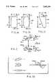
- FIG. 1A, FIG. 1B and FIG. 1Care side views of three representative foils suitable for use in practicing the teachings of this invention which are utilized to illustrate various parameters.
- FIG. 2is a top view of two foils operating in accordance with the teachings of this invention which illustrates additional parameters.
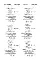
- FIGS. 3A-3Gare diagrams illustrating the relative heave and pitch positions of a foil for various phase angle differences ⁇ , with FIG. 3G illustrating the situation where there is a +10° bias angle.
- FIG. 4Ais a diagrammatic rear view of an illustrative embodiment of a marine propulsion system in accordance with the teachings of this invention.
- FIG. 4Bis a diagrammatic side view taken generally along the line B--B in FIG. 4A.
- FIGS. 5A-5Care more detailed rear, side and top views, respectively, for a marine drive system of the type shown in FIGS. 4A and 4B.
- FIG. 6Ais a chart illustrating the relationship between Strouhal number St and efficiency for a representative foil under various operating conditions.
- FIG. 6Bis a chart illustrating the relationship between Strouhal number and coefficient of thrust for a representative foil under various operating conditions.
- FIGS. 1A, 1B and 1Care side views of illustrative foils 10A,10B and 10C, respectively, having different shapes which may be utilized in practicing the teachings of this invention.
- FIG. 2is a top view which might be appropriate for any of the foils 10A, 10B or 10C.
- the exact shape of the foil used in practicing the teachings of this inventionis not critical and will vary with application. Examples of foils suitable for use are NACA type foils, although the invention is not limited to the use of such foils. Where the foil has a substantially rectangular shape as shown for foil 10A, the span S would be substantially the height of the foil and the chord c would be substantially the width of the foil.
- the span S and chord cwould be the average height and width, respectively, of the foil.
- the area A 0 for the foilis defined as Sc (i.e. the span times the chord).
- Each foilis pitched or pivoted about a pivot point 12 which is spaced by a distance b from the leading edge 14 of the foil.
- Leading edge 14faces in the direction in which the vessel to which the foil is attached is normally moving.
- the side opposite leading edge 14is trailing edge 16.
- foils 10(1) and 10(2)are spaced at their pivot points 12 by a distance D when both foils are at their center positions 18(1), 18(2), respectively.
- Each foilis oscillated (i.e. undergoes heave movement) to move its pivot point 12 through a cycle around the corresponding center line 18 in a periodic pattern (which is preferably a sinewave), with the maximum excursions on each side of the center line 18 being by an amount (a).
- (a)is preferably determined as a function of chord length c.
- the motions of the two foils 10(1), 10(2)are preferably 180° out-of-phase with each other so that Y(t) avg for the two foils is always substantially zero. This prevents undesired side thrust on the vessel being driven which could cause a fishtailing effect and the relationship should remain true regardless of the number of foils utilized. For example, if three foils were utilized, the foils would each be 120° out-of-phase so as to maintain the desired average Y(t) of zero.
- Each of the foilsalso has a ⁇ (t) relative to the direction of motion U which is determined by the relationship:
- ⁇the phase angle between the heave and pitch for the foil and ⁇ is a bias angle.
- ⁇is 0 for forward motion of the vessel and may be varied, preferably by angles ranging up to ⁇ 10°, to turn the vessel.
- FIG. 3Gillustrates the effect of a +10° bias angle on foil position for a single foil and this effect will be discussed in conjunction with FIG. 3G.
- the pitchis zero at the maximum extent of the heave or oscillating movement and the pitch is maximum at the midpoint of the oscillation.
- the maximum pitch anglesare in opposite direction depending on whether the foil is being moved in the positive or negative direction from its midposition.
- phase angles ⁇between roughly +70° and +120° when moving in a forward direction
- optimum phase angleis approximately +75°
- FIG. 3Billustrates the situation with a +75° phase angle.
- the maximum pitchoccurs slightly beyond the center or zero position for the oscillation in each direction and the pitch angle does not quite reach zero at the extremes of the heave movement, zero pitch angle occurring as the foil starts to move back toward its center position.
- FIG. 3Cillustrates the situation where the phase angle ⁇ is +120°.
- the maximum pitch angleoccurs prior to the midpoint of each heave or oscillation cycle in each direction and the zero pitch angle occurs prior to the foil reaching the extremes of its oscillations.
- the foilhas already started to move in the opposite direction from that in which it was moving during most of the corresponding heave movement.
- phase angles shown in FIGS. 3A-3Cresult in the vessel being driven by the foil being moved in a forward direction.
- the negative phase angles shown for FIGS. 3D-3Fresult in the vessel being moved backward.
- there is a negative phase angleso that the relationship between heave and pitch is the reverse of that shown for the corresponding phase angles in FIGS. 3A-3C, respectively.
- FIG. 3Dit is seen that the pitch angles at both extremes of the heave or oscillation for the foil are the same as for FIG. 3A, namely, 0°, but that the maximum pitch angle positions at the midpoint of the heave excursions are reversed.
- FIGS. 3B and 3Ewhich show the +75° and -75° phase angles
- FIGS. 3C and 3Fwhich illustrate the situations with a +120° and -120° phase angle, respectively.
- the pitch angleis 10° greater than it would be for the comparable phase angle and heave position without the bias angle.
- a turn in the negative directioni.e.
- a turn to the rightmay be effected by imposing for example up to a -10° bias angle on the foil.
- the actual bias anglewill vary depending on how sharp a turn is desired for the vessel, a larger bias angle resulting in a sharper turn. Therefore, a foil propulsion system is provided which enables a vessel being propelled by the system to move either forward or backward and to be turned in a desired direction when moving in either direction.
- FIG, 6Aillustrates the relationship between Strouhal number and efficiency for a foil which has the general shape of that shown in FIG. 1A.
- the curvesare for various nominal angles of attach ⁇ with all but the last two curves being for a phase angle of 90°.
- the last two curvesare at the phase angles indicated with a nominal angle of attach of 20°.
- a/cthe amplitude of oscillation divided by the foil chord
- a preferred value of approximately 1.5note that the nature of a and c will limit this value to probably not much over 3
- FIGS. 4A-4B and 5A-5Cillustrate a possible implementation for a foil propulsion system in accordance with the teachings of the invention.
- This embodimentis illustrated with respect to a marine propulsion application wherein a vessel 30, portions at the stern end of which are shown diagrammatically in the figures, is driven by a pair of foils 10(1) and 10(2).
- Each foilis suspended from the hull 32 of the vessel by a corresponding shaft 34(1),34(2).
- Each shaft 34passes through a corresponding slit 36(1),36(2) in hull 32, the extent of the slots 36 as viewed in FIG. 4A and as illustrated by the arrows 38 being greater than the total maximum heave amplitude for the foils.
- Each shaft 36is fixed to a corresponding table 40(1),40(2).
- each table 40has two or more wheels or rollers 42 mounted to the forward underside and to the rear underside, which wheels or rollers ride in corresponding tracks 44 mounted to hull 32.
- Tables 40 and the foils 10 attached theretoare thus free to move in the direction 38, but are not free to move in any other direction.
- FIGS. 5A-5Cillustrate the mechanism for driving one of the foils shown in FIGS. 4A-4B, it being understood that the mechanism of FIGS. 5A-5C would be repeated for each of the foils.
- shaft 34is also rigidly attached to one end of an arm 46, the other end of which is rotatably attached by a pin 48 to one end of an arm 50.
- the other end of arm 50is attached by a pin 52 to one end of an arm 54, the other end of arm 54 being rigidly attached to a shaft 56.
- Shaft 56also has attached thereto a wheel or disk 58 and a wheel 60.
- Wheel 58is attached by a belt 62 to be rotated by a motor 65 via a wheel 64 mounted to the motor shaft.
- Wheel 60has a pin 66 extended from a selected point thereon, which pin rides in a slot 68 formed in table 40, slot 68 extending in a direction generally perpendicular to direction 38.
- the rotation of shaft 56also causes arm 54 which is fixed thereto to rotate through a 360° path. This motion is imparted to arm 46 through arm 50, causing angular variations in the direction of arm 46 which result in angular rotations of shaft 34. Rotations of shaft 34 are imparted to foil 10 attached thereto, resulting in the desired pitch variations of the foil during its heave motion. The rotation of motor 65 is thus converted into the desired heave and pitch motion of the foil by the mechanism shown in FIGS. 5A-5C.
- each of the foils 10(1),10(2)is driven by a separate motor 65, it is desirable that these motors be maintained in synchronism to achieve optimum propulsion and to avoid side thrust forces.
- the motorsmay be maintained in synchronism utilizing standard motor synchronization techniques such as, for example, utilizing a feedback output from one of the motors, the master motor, to maintain the other motor, the slave motor, in synchronization therewith.
- a drive systemmay be designed which permits both foils to be driven from a single motor, eliminating the synchronization requirement.
- Various considerationswill determine whether the additional complexity in drive linkages required to operate two or more foils from a single motor is advantageous over utilizing a separate motor for each foil and providing suitable synchronization circuitry for such motors.
- FIG. 5Aalso shows a spring 71 attached at one end to table 40 and attached at the other end to the hull 32 or to some member fixed to the hull.
- Spring 71is preferably installed such that it is in its neutral position when table 40 is at the midpoint of its travel path so that the spring is stretched when the table is to the right of such center point as viewed in FIG. 5A and is in compression when the table is to the left of the center point.
- the springthus stores energy when the table is moving away from its center position and gives back energy when the table is moving back toward its center position. This storage and giving back of energy enhances the overall efficiency of the system.
- the springWhen the spring, and the mass of the table (plus all other moving equipment) have a natural frequency which is near the operating frequency f for the system, optimal use of the spring is achieved. Since the frequency f varies with the speed at which the vessel is moving, the spring is typically designed to achieve optimal operation at the frequency for the normal cruising speed of the vessel since this is the frequency at which the system will most often be operating. While only a single spring is shown in FIG. 5A, it is to be understood that an additional spring may be provided on the opposite side of table 40 from spring 71 to provide more balanced forces and that additional springs 71 may also be provided. Other mechanisms known in the art which are adapted to store and return energy might also be used in place of springs 71 to achieve this function. Where the use of such mechanism is potentially detrimental at non-resonant frequencies, suitable mechanisms may be provided to disable the energy storing mechanism until the vessel reaches its normal cruising speed so that the mechanism is most effectively utilized.
- the amplitude (a) of the heave motionis roughly equal to the distance between shaft 56 and pin 66 and may thus be controlled by varying this distance. This may be achieved by moving pin 66 along a radius line of wheel 60 either toward or away from shaft 56, either under manual or computer control, until the spacing is suitable to provide the desired heave amplitude. Pin 66 could for example be positioned in a radial slot 69 in wheel 60 as shown in FIG. 5C to permit the amplitude heave adjustment.
- the maximum pitch angles ⁇ 0are determined by the ratio of the length of arm 54 to the length of arm 46. This ratio may thus be controlled by varying the length of either arm 46 or arm 54, the control being illustrated in FIG. 5C by a pneumatic or hydraulic joint 70 in arm 54 which may be utilized under either manual or computer control to vary the length of this arm. Alternatively, a similar joint may be placed in arm 46.
- the phase anglemay be changed by varying the angular position on wheel 60 of pin 66 relative to the angular position of arm 54. Stated another way, this is accomplished by varying the angular position of arm 54 on shaft 56. This adjustment may be accomplished, for example, by providing a small stepping motor 72 in shaft 56 as shown in FIG. 5A to permit the relative angular position of the upper part of this shaft to which arm 54 is pinned or otherwise connected to the lower part of this shaft to which wheel 60 is connected. Stepping motor 72 may be controlled either manually or by computer. Other suitable means might be provided for permitting controlled rotation of arm 54 on shaft 56. As discussed earlier, vessel 30 moves forward for positive phase angles and will move backward for negative phase angles.
- a bias anglecan be imparted to the system.
- this objectivemay be accomplished by providing a small stepping motor 74 in shaft 34 to cause a controlled rotation of the upper part of this shaft to which arm 46 is connected from the lower part of the shaft to which foil 10 is connected at its pivot point 12.
- the amount of this change and the direction of this changewill correspond to the desired bias angle.
- This changewould typically be made under computer control based on the desired turn which is inputted into the system, but could also be accomplished in response to a manual input.
- Other techniques for permitting controlled rotation of arm 46 or foil 10 relative to shaft 34 and/or to the other elementcould also be utilized to effect the bias control.
- foils mounted to the stern of the vessel 30have been shown in the figures, this is not a limitation on the invention and the number and placement of foils will typically depend on the type of vessel, including size and weight, required speed, the use of the vessel, including available draft, wetted areas, speed requirements and available locations for the foils.
- an even number of foilsis desirable in that it permits the balancing of side thrust forces by merely having the heave for half the foils be 180° out-of-phase with the heave for the remaining foils, this objective can be obtained in other ways. For example, with three foils, each foil could be 120° out-of-phase with the other foils to provide the desired balanced forces.
- a curve for a resistance value R versus speed U for the vehicleis determined from the relationship:
- ⁇is the density of water
- C ris a resistance coefficient for the vessel which may be determined experimentally or may be estimated for a particular vessel based on its size and shape
- a wis the wetted area of the vessel, which area will vary with load.
- C tis the thrust coefficient for a single foil, which coefficient is a function of foil shape and other factors and may be obtained from tests on the foil or estimated from similar prior used foils. Tables can be developed to provide C t for common foil types.
- the offset b to the pivot pointmay be determined so as to be within the range previously specified (most likely value b/c ⁇ 0.3).
- the amplitude of oscillation ais determined from the chord c from the relationship 2a ⁇ 3c. It is noted that this equation gives a maximum value of amplitude beyond which there may be some interaction between the foils and an amplitude less than the value given above may be utilized.
- Phase angle ⁇is selected to be within the recommended range, with +75° being the preferred value were b/c ⁇ 0.3.
- the angle of attack ⁇is selected to be within the recommended range with a preferred value of approximately 20°. This value along with the other values previously determined may be utilized to determine the maximum pitch angle ⁇ 0 for the foil from the relationship.
- the frequency fis found by choosing the Strouhal number in the recommended range, preferably about 0.35, from the relationship ##EQU5## While in the discussion above it has been assumed that the foils are being used as part of a marine propulsion system, and this is clearly the preferred application of the invention, it might also be possible to utilize the invention in place of a propeller in propelling vehicles in fluids (i.e.
- the inventionmay also be advantageously utilized in human powered systems with motions of a swimmer's legs being converted by suitable mechanical linkages into heave and pitch motion for one or more foils in accordance with the teachings of this invention.
- Such devicescan provide faster motion with less exertion than currently available systems for propelling a swimmer or diver without a drive motor.
Landscapes
- Chemical & Material Sciences (AREA)
- Engineering & Computer Science (AREA)
- Combustion & Propulsion (AREA)
- Mechanical Engineering (AREA)
- Ocean & Marine Engineering (AREA)
- Other Liquid Machine Or Engine Such As Wave Power Use (AREA)
- Toys (AREA)
- Percussion Or Vibration Massage (AREA)
- Structures Of Non-Positive Displacement Pumps (AREA)
Abstract
Description
θ(t)=θ.sub.0 sin(2πft+ψ)+θ
R=1/2(ρC.sub.r A.sub.w U.sup.2)
Claims (24)
Y(t)=a sin (2πft)
θ(t)=θ.sub.o sin (2πft+ψ)+θ
Priority Applications (6)
| Application Number | Priority Date | Filing Date | Title |
|---|---|---|---|
| US08/154,260US5401196A (en) | 1993-11-18 | 1993-11-18 | Propulsion mechanism employing flapping foils |
| PCT/US1994/013337WO1995013959A1 (en) | 1993-11-18 | 1994-11-17 | Propulsion mechanism employing flapping foils |
| AT95902607TATE170477T1 (en) | 1993-11-18 | 1994-11-17 | DRIVE MECHANISM WITH SWINGING WINGS |
| EP95902607AEP0728099B1 (en) | 1993-11-18 | 1994-11-17 | Propulsion mechanism employing flapping foils |
| KR1019960702646AKR100392745B1 (en) | 1993-11-18 | 1994-11-17 | Propulsion mechanism using flapping foil |
| DE69413056TDE69413056T2 (en) | 1993-11-18 | 1994-11-17 | DRIVE MECHANISM WITH SWINGING WINGS |
Applications Claiming Priority (1)
| Application Number | Priority Date | Filing Date | Title |
|---|---|---|---|
| US08/154,260US5401196A (en) | 1993-11-18 | 1993-11-18 | Propulsion mechanism employing flapping foils |
Publications (1)
| Publication Number | Publication Date |
|---|---|
| US5401196Atrue US5401196A (en) | 1995-03-28 |
Family
ID=22550644
Family Applications (1)
| Application Number | Title | Priority Date | Filing Date |
|---|---|---|---|
| US08/154,260Expired - LifetimeUS5401196A (en) | 1993-11-18 | 1993-11-18 | Propulsion mechanism employing flapping foils |
Country Status (6)
| Country | Link |
|---|---|
| US (1) | US5401196A (en) |
| EP (1) | EP0728099B1 (en) |
| KR (1) | KR100392745B1 (en) |
| AT (1) | ATE170477T1 (en) |
| DE (1) | DE69413056T2 (en) |
| WO (1) | WO1995013959A1 (en) |
Cited By (49)
| Publication number | Priority date | Publication date | Assignee | Title |
|---|---|---|---|---|
| WO1997045317A1 (en)* | 1996-05-28 | 1997-12-04 | Massachusetts Institute Of Technology | Method and apparatus for reducing drag on a moving body |
| WO1997048599A1 (en)* | 1996-06-17 | 1997-12-24 | Horrigan David J P | Symmetrical foil for moving fluids |
| WO1997049603A1 (en)* | 1996-06-25 | 1997-12-31 | Giuseppe Pollastri | A marine oscillatory-motion propulsion system |
| US5975462A (en)* | 1996-10-30 | 1999-11-02 | The United States Of America As Represented By The Secretary Of The Navy | Integrated propulsion/lift/control system for aircraft and ship applications |
| US6086440A (en)* | 1999-01-11 | 2000-07-11 | Fechtner; Ryszard | Swim fin and monofin with flapping foil |
| US6138604A (en)* | 1998-05-26 | 2000-10-31 | The Charles Stark Draper Laboratories, Inc. | Pelagic free swinging aquatic vehicle |
| US6193466B1 (en) | 1999-02-11 | 2001-02-27 | Milan Dennis Earl | Counter rotating bypass propeller |
| US6375530B1 (en) | 2001-01-31 | 2002-04-23 | Milan Dennis Earl | Whaletail swimming device |
| US6558210B2 (en) | 2001-08-29 | 2003-05-06 | Charles Consolvo Frasier | Device for propelling a diver through a body of water using pedaling motion |
| US20040195440A1 (en)* | 2003-03-05 | 2004-10-07 | Pengfei Liu | Oscillating foil propulsion system |
| US6835108B1 (en) | 2004-01-12 | 2004-12-28 | The United States Of America As Represented By The Secretary Of The Navy | Oscillating appendage for fin propulsion |
| US20060019555A1 (en)* | 2003-05-14 | 2006-01-26 | Mcguinness Thomas G | Vessel propelled by oscillating fin with control mechanisms |
| US20060102782A1 (en)* | 2004-11-02 | 2006-05-18 | Earl Milan D | Flying device utilizing natural principles |
| US20070219068A1 (en)* | 2004-09-19 | 2007-09-20 | Georg Korfmacher | Method and apparatus for controlling repetitive movements |
| US7300323B1 (en) | 2006-05-30 | 2007-11-27 | The United States Of America Represented By The Secretary Of The Navy | Linear actuator for flapping hydrofoil |
| US20090076670A1 (en)* | 2007-09-17 | 2009-03-19 | Bandyopadhyay Promode R | Olivo-Cerebellar Controller |
| WO2009074580A1 (en) | 2007-12-10 | 2009-06-18 | A.P. Møller-Mærsk A/S | A fin propulsion apparatus |
| WO2009074578A1 (en)* | 2007-12-10 | 2009-06-18 | A.P. Møller-Mærsk A/S | Translating chariot for fin propulsion |
| WO2009074579A1 (en)* | 2007-12-10 | 2009-06-18 | A.P. Møller-Mærsk A/S | Fin propulsion by means of inclined fins |
| WO2009074581A1 (en)* | 2007-12-10 | 2009-06-18 | A.P. Møller-Mærsk A/S | Sealing for fin propulsion |
| US20090191772A1 (en)* | 2008-01-24 | 2009-07-30 | Wu Chun-Kai | Oscillating-foil type underwater propulsor with a joint |
| US7869910B1 (en)* | 2007-09-14 | 2011-01-11 | The United States Of America As Represented By The Secretary Of The Navy | Auto-catalytic oscillators for locomotion of underwater vehicles |
| US20110028056A1 (en)* | 2008-03-07 | 2011-02-03 | Mark Paish | Apparatus for oscillating and orienting a vane and a vessel including such an apparatus |
| US20110255971A1 (en)* | 2008-08-18 | 2011-10-20 | Bas Goris DBA Oscillating Foul Development | Apparatus for oscillating a foil in a fluid |
| WO2013014232A1 (en) | 2011-07-27 | 2013-01-31 | A.P. Møller-Mærsk A/S | Driving and guiding method for marine propulsion with fins on an endless- path |
| WO2013014061A1 (en) | 2011-07-27 | 2013-01-31 | A.P. Møller - Mærsk A/S | Sealing for fin propulsion with endless path |
| KR101323795B1 (en)* | 2011-11-15 | 2013-10-31 | 삼성중공업 주식회사 | Ship |
| US8641464B2 (en) | 2010-04-08 | 2014-02-04 | Cetatek Holdings Inc. | Flippers, boots, systems including same, and methods of using same |
| US20140109821A1 (en)* | 2012-10-19 | 2014-04-24 | Boston Engineering Corporation | Aquatic Vehicle |
| WO2014089704A1 (en)* | 2012-12-14 | 2014-06-19 | Brice Thouret | Propulsion device for use with a fluid |
| WO2015006514A1 (en)* | 2013-07-09 | 2015-01-15 | Horrigan David | Propelling objects using a caudal cycle |
| US9045211B2 (en) | 2013-09-17 | 2015-06-02 | The United States Of America, As Represented By The Secretary Of The Navy | Actively controlled curvature robotic pectoral fin |
| US9061750B2 (en) | 2013-01-19 | 2015-06-23 | Bartley D. Jones | Watercraft propulsion system |
| US20150329186A1 (en)* | 2014-05-14 | 2015-11-19 | Abb Oy | Oscillating foil propulsion system and method for controlling a motion of an oscillating movable foil |
| WO2016012656A1 (en)* | 2014-07-24 | 2016-01-28 | Abb Oy | Dual mode oscillating foil propulsion system and method for oscillating at least one movable foil |
| US9440114B2 (en) | 2012-10-12 | 2016-09-13 | Cetatek Holdings Inc. | Boot sole system and fin for same |
| CN106021686A (en)* | 2016-05-16 | 2016-10-12 | 哈尔滨电机厂有限责任公司 | Method for estimating Karman vortex frequency of blunt outlet edge of movable guide vane of hydraulic turbine |
| US20170152011A1 (en)* | 2014-07-08 | 2017-06-01 | Jiangsu University Of Science And Technology | Bionic Pectoral Fin Propelling Device Based on Planetary Gear Train |
| WO2018073493A1 (en) | 2016-10-17 | 2018-04-26 | Teknologian Tutkimuskeskus Vtt Oy | Energy transforming device and method of transforming energy |
| GB2564375A (en)* | 2017-05-17 | 2019-01-16 | Joseph Rotherham James | Aircraft propulsion system, method of manufacture and use thereof |
| US10343754B1 (en)* | 2014-11-17 | 2019-07-09 | Joseph D Maresh | Oscillating fin propulsion apparatus |
| US10675508B2 (en) | 2010-04-08 | 2020-06-09 | Cetatek Holdings Inc. | Coupleable fin apparatuses and boot toe bodies |
| CN111611652A (en)* | 2020-06-04 | 2020-09-01 | 电子科技大学 | A method for analyzing aerodynamic characteristics of flapping wings based on active flexible deformation |
| CN112407139A (en)* | 2020-11-14 | 2021-02-26 | 西北工业大学 | Flapping wing wake flow control active drag reduction method for underwater vehicle |
| RU204567U1 (en)* | 2020-09-15 | 2021-05-31 | Виктор Васильевич Редькин | Finned propulsion and steering device with hydrogenerator |
| CN112918644A (en)* | 2021-01-26 | 2021-06-08 | 南京航空航天大学 | Bionic motion method of multi-pair parallel pectoral fin bionic ray robot based on MPF |
| WO2022043368A1 (en) | 2020-08-28 | 2022-03-03 | Francis Rey | Device driving the flapping of a carrier plane |
| CN114542378A (en)* | 2022-04-26 | 2022-05-27 | 东方电气风电股份有限公司 | Method for dynamically calculating optimal minimum pitch angle of wind generating set |
| SE2251585A1 (en)* | 2022-12-28 | 2024-06-29 | Dolprop Ind Ab | Drive mechanism for a fluke drive and method for installing the same |
Families Citing this family (1)
| Publication number | Priority date | Publication date | Assignee | Title |
|---|---|---|---|---|
| FR2797428B1 (en) | 1999-08-09 | 2002-01-18 | Thomas Langrand | DEVICE FOR PROPELLING A MACHINE FOR MOVING IN OR ON A FLUID |
Citations (4)
| Publication number | Priority date | Publication date | Assignee | Title |
|---|---|---|---|---|
| US4490119A (en)* | 1983-03-21 | 1984-12-25 | Young Ronald G | Boat propulsion apparatus |
| DE3701151A1 (en)* | 1986-03-18 | 1988-07-28 | Hans Raehmer | Flapping-wing drive system |
| US5000706A (en)* | 1989-10-20 | 1991-03-19 | Wang June C | Rocker type propulsion mechanism for a boat |
| US5021015A (en)* | 1990-02-20 | 1991-06-04 | Wang June Chi | Propulsion mechanism for a boat |
Family Cites Families (4)
| Publication number | Priority date | Publication date | Assignee | Title |
|---|---|---|---|---|
| GB687170A (en)* | 1950-08-03 | 1953-02-11 | Richard Gardner | Oscillating vane propeller |
| FR1330218A (en)* | 1962-05-07 | 1963-06-21 | Nautical propulsion device | |
| FR2278565A1 (en)* | 1974-05-28 | 1976-02-13 | Bouix Maurice | Flap type marine propulsion system - has flaps operated by alternative mechanisms to give sinusoidal or cycloidal motion |
| DE2628846C2 (en)* | 1976-06-26 | 1981-09-24 | Horst 8500 Nürnberg Räbiger | Torsional swing engine |
- 1993
- 1993-11-18USUS08/154,260patent/US5401196A/ennot_activeExpired - Lifetime
- 1994
- 1994-11-17DEDE69413056Tpatent/DE69413056T2/ennot_activeExpired - Fee Related
- 1994-11-17EPEP95902607Apatent/EP0728099B1/ennot_activeExpired - Lifetime
- 1994-11-17WOPCT/US1994/013337patent/WO1995013959A1/enactiveIP Right Grant
- 1994-11-17KRKR1019960702646Apatent/KR100392745B1/ennot_activeExpired - Fee Related
- 1994-11-17ATAT95902607Tpatent/ATE170477T1/enactive
Patent Citations (4)
| Publication number | Priority date | Publication date | Assignee | Title |
|---|---|---|---|---|
| US4490119A (en)* | 1983-03-21 | 1984-12-25 | Young Ronald G | Boat propulsion apparatus |
| DE3701151A1 (en)* | 1986-03-18 | 1988-07-28 | Hans Raehmer | Flapping-wing drive system |
| US5000706A (en)* | 1989-10-20 | 1991-03-19 | Wang June C | Rocker type propulsion mechanism for a boat |
| US5021015A (en)* | 1990-02-20 | 1991-06-04 | Wang June Chi | Propulsion mechanism for a boat |
Non-Patent Citations (4)
| Title |
|---|
| G. S. Triantafyliou, et al, Optimal Thrust Development in Oscillating Foils with Application to Fish Propulsion, pp. 205 224, Journal of Fluids and Structures 1993.* |
| G. S. Triantafyliou, et al, Optimal Thrust Development in Oscillating Foils with Application to Fish Propulsion, pp. 205-224, Journal of Fluids and Structures 1993. |
| M. S. Triantafyllou, et al, Wake Mechanics for Thrust Generation in Oscillating Foils, Dec. 1991, pp. 2835 2837, American Institute of Physics, Phys. Fluids A3 (12).* |
| M. S. Triantafyllou, et al, Wake Mechanics for Thrust Generation in Oscillating Foils, Dec. 1991, pp. 2835-2837, American Institute of Physics, Phys. Fluids A3 (12). |
Cited By (80)
| Publication number | Priority date | Publication date | Assignee | Title |
|---|---|---|---|---|
| WO1997045317A1 (en)* | 1996-05-28 | 1997-12-04 | Massachusetts Institute Of Technology | Method and apparatus for reducing drag on a moving body |
| US5740750A (en)* | 1996-05-28 | 1998-04-21 | Massachusetts Institute Of Technology | Method and apparatus for reducing drag on a moving body |
| US5997369A (en)* | 1996-05-28 | 1999-12-07 | Massachusetts Institute Of Technology | Human powered marine vehicle and method for the operation thereof |
| WO1997048599A1 (en)* | 1996-06-17 | 1997-12-24 | Horrigan David J P | Symmetrical foil for moving fluids |
| WO1997049603A1 (en)* | 1996-06-25 | 1997-12-31 | Giuseppe Pollastri | A marine oscillatory-motion propulsion system |
| US5975462A (en)* | 1996-10-30 | 1999-11-02 | The United States Of America As Represented By The Secretary Of The Navy | Integrated propulsion/lift/control system for aircraft and ship applications |
| US6138604A (en)* | 1998-05-26 | 2000-10-31 | The Charles Stark Draper Laboratories, Inc. | Pelagic free swinging aquatic vehicle |
| US6086440A (en)* | 1999-01-11 | 2000-07-11 | Fechtner; Ryszard | Swim fin and monofin with flapping foil |
| US6193466B1 (en) | 1999-02-11 | 2001-02-27 | Milan Dennis Earl | Counter rotating bypass propeller |
| US6375530B1 (en) | 2001-01-31 | 2002-04-23 | Milan Dennis Earl | Whaletail swimming device |
| US6558210B2 (en) | 2001-08-29 | 2003-05-06 | Charles Consolvo Frasier | Device for propelling a diver through a body of water using pedaling motion |
| US20040195440A1 (en)* | 2003-03-05 | 2004-10-07 | Pengfei Liu | Oscillating foil propulsion system |
| US6877692B2 (en)* | 2003-03-05 | 2005-04-12 | National Research Council Of Canada | Oscillating foil propulsion system |
| US20060019555A1 (en)* | 2003-05-14 | 2006-01-26 | Mcguinness Thomas G | Vessel propelled by oscillating fin with control mechanisms |
| US6997765B1 (en) | 2003-05-14 | 2006-02-14 | Mcguinness Thomas G | Vessel propelled by oscillating fin with control mechanisms |
| US6835108B1 (en) | 2004-01-12 | 2004-12-28 | The United States Of America As Represented By The Secretary Of The Navy | Oscillating appendage for fin propulsion |
| US20070219068A1 (en)* | 2004-09-19 | 2007-09-20 | Georg Korfmacher | Method and apparatus for controlling repetitive movements |
| US20060102782A1 (en)* | 2004-11-02 | 2006-05-18 | Earl Milan D | Flying device utilizing natural principles |
| US7255305B2 (en) | 2004-11-02 | 2007-08-14 | Milan Dennis Earl | Flying device utilizing natural principles |
| US7300323B1 (en) | 2006-05-30 | 2007-11-27 | The United States Of America Represented By The Secretary Of The Navy | Linear actuator for flapping hydrofoil |
| US7869910B1 (en)* | 2007-09-14 | 2011-01-11 | The United States Of America As Represented By The Secretary Of The Navy | Auto-catalytic oscillators for locomotion of underwater vehicles |
| US8065046B2 (en)* | 2007-09-17 | 2011-11-22 | The United States Of America As Represented By The Secretary Of The Navy | Olivo-cerebellar controller |
| US20090076670A1 (en)* | 2007-09-17 | 2009-03-19 | Bandyopadhyay Promode R | Olivo-Cerebellar Controller |
| WO2009074579A1 (en)* | 2007-12-10 | 2009-06-18 | A.P. Møller-Mærsk A/S | Fin propulsion by means of inclined fins |
| WO2009074581A1 (en)* | 2007-12-10 | 2009-06-18 | A.P. Møller-Mærsk A/S | Sealing for fin propulsion |
| US20100291814A1 (en)* | 2007-12-10 | 2010-11-18 | Jacob Govert Vermeiden | fin propulsion apparatus |
| CN101909983A (en)* | 2007-12-10 | 2010-12-08 | A.P.穆勒-马士基有限公司 | Translating chariot for fin propulsion |
| CN101909985A (en)* | 2007-12-10 | 2010-12-08 | A.P.穆勒-马士基有限公司 | Sealing for fin propulsion |
| WO2009074580A1 (en) | 2007-12-10 | 2009-06-18 | A.P. Møller-Mærsk A/S | A fin propulsion apparatus |
| WO2009074578A1 (en)* | 2007-12-10 | 2009-06-18 | A.P. Møller-Mærsk A/S | Translating chariot for fin propulsion |
| US20090191772A1 (en)* | 2008-01-24 | 2009-07-30 | Wu Chun-Kai | Oscillating-foil type underwater propulsor with a joint |
| US7744434B2 (en)* | 2008-01-24 | 2010-06-29 | Chang Jung Christian University | Oscillating-foil type underwater propulsor with a joint |
| US20110028056A1 (en)* | 2008-03-07 | 2011-02-03 | Mark Paish | Apparatus for oscillating and orienting a vane and a vessel including such an apparatus |
| US20110255971A1 (en)* | 2008-08-18 | 2011-10-20 | Bas Goris DBA Oscillating Foul Development | Apparatus for oscillating a foil in a fluid |
| US8641464B2 (en) | 2010-04-08 | 2014-02-04 | Cetatek Holdings Inc. | Flippers, boots, systems including same, and methods of using same |
| US10675508B2 (en) | 2010-04-08 | 2020-06-09 | Cetatek Holdings Inc. | Coupleable fin apparatuses and boot toe bodies |
| US10112079B2 (en) | 2010-04-08 | 2018-10-30 | Cetatek Holdings Inc. | Flippers, boots, systems including same, and methods of using same |
| US9737762B2 (en) | 2010-04-08 | 2017-08-22 | Cetatek Holdings Inc. | Flippers, boots, systems including same, and methods of using same |
| WO2013014232A1 (en) | 2011-07-27 | 2013-01-31 | A.P. Møller-Mærsk A/S | Driving and guiding method for marine propulsion with fins on an endless- path |
| WO2013014061A1 (en) | 2011-07-27 | 2013-01-31 | A.P. Møller - Mærsk A/S | Sealing for fin propulsion with endless path |
| KR101323795B1 (en)* | 2011-11-15 | 2013-10-31 | 삼성중공업 주식회사 | Ship |
| US9440114B2 (en) | 2012-10-12 | 2016-09-13 | Cetatek Holdings Inc. | Boot sole system and fin for same |
| US20140109821A1 (en)* | 2012-10-19 | 2014-04-24 | Boston Engineering Corporation | Aquatic Vehicle |
| US9090320B2 (en)* | 2012-10-19 | 2015-07-28 | Boston Engineering Corporation | Aquatic vehicle |
| US8784148B2 (en) | 2012-12-14 | 2014-07-22 | Brice Thouret | Propulsion device for use with a fluid |
| US9315249B2 (en) | 2012-12-14 | 2016-04-19 | Brice Thouret | Propulsion device for use with a fluid |
| WO2014089704A1 (en)* | 2012-12-14 | 2014-06-19 | Brice Thouret | Propulsion device for use with a fluid |
| US9061750B2 (en) | 2013-01-19 | 2015-06-23 | Bartley D. Jones | Watercraft propulsion system |
| KR20160077029A (en)* | 2013-07-09 | 2016-07-01 | 호리간 코포레이션 | Propelling objects using a caudal cycle |
| GB2530227A (en)* | 2013-07-09 | 2016-03-16 | David Horrigan | Propelling objects using a caudal cycle |
| US20160152309A1 (en)* | 2013-07-09 | 2016-06-02 | David Horrigan | Propelling objects using a caudal cycle |
| WO2015006514A1 (en)* | 2013-07-09 | 2015-01-15 | Horrigan David | Propelling objects using a caudal cycle |
| US10618616B2 (en) | 2013-07-09 | 2020-04-14 | Horrigan Corporation | Propelling objects using a caudal cycle |
| JP2016536508A (en)* | 2013-07-09 | 2016-11-24 | ホリガン コーポレーションHorrigan Corporation | Apparatus and method for propelling gases, fluids, and objects using a tail cycle |
| DE112014003201B4 (en) | 2013-07-09 | 2023-11-23 | David Horrigan | Propelling objects using a fin drive |
| GB2530227B (en)* | 2013-07-09 | 2019-10-16 | Horrigan David | Propelling objects using a caudal cycle |
| US9045211B2 (en) | 2013-09-17 | 2015-06-02 | The United States Of America, As Represented By The Secretary Of The Navy | Actively controlled curvature robotic pectoral fin |
| US9120546B1 (en) | 2013-09-17 | 2015-09-01 | The United States Of America, As Represented By The Secretary Of The Navy | Actively controlled curvature robotic pectoral fin |
| US20150329186A1 (en)* | 2014-05-14 | 2015-11-19 | Abb Oy | Oscillating foil propulsion system and method for controlling a motion of an oscillating movable foil |
| US20170152011A1 (en)* | 2014-07-08 | 2017-06-01 | Jiangsu University Of Science And Technology | Bionic Pectoral Fin Propelling Device Based on Planetary Gear Train |
| US9771135B2 (en)* | 2014-07-08 | 2017-09-26 | Jiangsu University Of Science And Technology | Bionic pectoral fin propelling device based on planetary gear train |
| WO2016012656A1 (en)* | 2014-07-24 | 2016-01-28 | Abb Oy | Dual mode oscillating foil propulsion system and method for oscillating at least one movable foil |
| US10343754B1 (en)* | 2014-11-17 | 2019-07-09 | Joseph D Maresh | Oscillating fin propulsion apparatus |
| CN106021686B (en)* | 2016-05-16 | 2018-12-11 | 哈尔滨电机厂有限责任公司 | Water turbine movable guide vane root face outlet edge Karman vortices predictor method |
| CN106021686A (en)* | 2016-05-16 | 2016-10-12 | 哈尔滨电机厂有限责任公司 | Method for estimating Karman vortex frequency of blunt outlet edge of movable guide vane of hydraulic turbine |
| WO2018073493A1 (en) | 2016-10-17 | 2018-04-26 | Teknologian Tutkimuskeskus Vtt Oy | Energy transforming device and method of transforming energy |
| US11479330B2 (en) | 2016-10-17 | 2022-10-25 | Teknologian Tutkimuskeskus Vtt Oy | Energy transforming device and method of transforming energy |
| GB2564375A (en)* | 2017-05-17 | 2019-01-16 | Joseph Rotherham James | Aircraft propulsion system, method of manufacture and use thereof |
| GB2564375B (en)* | 2017-05-17 | 2022-08-10 | Joseph Rotherham James | Aircraft propulsion system, method of manufacture and use thereof |
| CN110869279A (en)* | 2017-05-17 | 2020-03-06 | J·J·罗瑟勒姆 | Aircraft propulsion system, method of manufacture and use thereof |
| CN111611652A (en)* | 2020-06-04 | 2020-09-01 | 电子科技大学 | A method for analyzing aerodynamic characteristics of flapping wings based on active flexible deformation |
| CN111611652B (en)* | 2020-06-04 | 2023-06-09 | 电子科技大学 | A Method for Analyzing Aerodynamic Characteristics of Flapping Wing Based on Active Flexible Deformation |
| WO2022043368A1 (en) | 2020-08-28 | 2022-03-03 | Francis Rey | Device driving the flapping of a carrier plane |
| FR3113643A1 (en) | 2020-08-28 | 2022-03-04 | Francis REY | TRAINING DEVICE FOR A SUPPORTING PLANE |
| RU204567U1 (en)* | 2020-09-15 | 2021-05-31 | Виктор Васильевич Редькин | Finned propulsion and steering device with hydrogenerator |
| CN112407139A (en)* | 2020-11-14 | 2021-02-26 | 西北工业大学 | Flapping wing wake flow control active drag reduction method for underwater vehicle |
| CN112918644A (en)* | 2021-01-26 | 2021-06-08 | 南京航空航天大学 | Bionic motion method of multi-pair parallel pectoral fin bionic ray robot based on MPF |
| CN114542378A (en)* | 2022-04-26 | 2022-05-27 | 东方电气风电股份有限公司 | Method for dynamically calculating optimal minimum pitch angle of wind generating set |
| SE2251585A1 (en)* | 2022-12-28 | 2024-06-29 | Dolprop Ind Ab | Drive mechanism for a fluke drive and method for installing the same |
| WO2024144445A1 (en)* | 2022-12-28 | 2024-07-04 | Dolprop Industries Ab | Drive mechanism for a fluke drive and method for installing the same |
Also Published As
| Publication number | Publication date |
|---|---|
| KR960705716A (en) | 1996-11-08 |
| EP0728099A1 (en) | 1996-08-28 |
| KR100392745B1 (en) | 2004-03-22 |
| ATE170477T1 (en) | 1998-09-15 |
| EP0728099B1 (en) | 1998-09-02 |
| DE69413056D1 (en) | 1998-10-08 |
| WO1995013959A1 (en) | 1995-05-26 |
| DE69413056T2 (en) | 1999-03-18 |
Similar Documents
| Publication | Publication Date | Title |
|---|---|---|
| US5401196A (en) | Propulsion mechanism employing flapping foils | |
| US5740750A (en) | Method and apparatus for reducing drag on a moving body | |
| US6997765B1 (en) | Vessel propelled by oscillating fin with control mechanisms | |
| RU2482012C2 (en) | Fin propulsor | |
| JP2015217940A (en) | Oscillating foil propulsion system and method for controlling the motion of an oscillating movable foil | |
| CN114450221A (en) | Device for moving a ship | |
| US7048506B2 (en) | Method and apparatus for magnetic actuation of variable pitch impeller blades | |
| JPS5857084A (en) | Wind power plant | |
| JP2920206B2 (en) | Internally driven flapping thruster | |
| US10272981B2 (en) | Watercraft | |
| WO1998039205A1 (en) | Undulating propeller using the energy generated by pitching of the vessel | |
| US6926566B2 (en) | Method and apparatus for synchronous impeller pitch vehicle control | |
| Kaeli et al. | Asymmetric propulsion: Thrust and maneuverability from a single degree of freedom | |
| WO2009083892A2 (en) | Device for stabilising the rolling motion of boats. | |
| JPH0230920B2 (en) | HAKUYOPUROPERASOCHI | |
| JP2011506172A (en) | Translational carriage for fin propulsion | |
| JPS60104491A (en) | Catamaran provided with wave energy absorbing fin | |
| CN1095785C (en) | Device for ships, independent of principle propulsion system, serving either as passive rudder or as active manoeuvring element | |
| US6240869B1 (en) | Watercraft stabilization apparatus | |
| RU2248302C1 (en) | Marine propulsion plant of "steering nozzle" type | |
| JPH07205891A (en) | Motion controlling actuator for navigating body | |
| JPS59195495A (en) | Variable pitch type rudder propeller and method of operating thereof | |
| RU167128U1 (en) | VESSEL ENGINE | |
| JPS63312298A (en) | Steering gear | |
| JPH0732376Y2 (en) | Swing angle change type stable fin |
Legal Events
| Date | Code | Title | Description |
|---|---|---|---|
| AS | Assignment | Owner name:MASSACHUSETTS INSTITUTE OF TECHNOLOGY, MASSACHUSET Free format text:ASSIGNMENT OF ASSIGNORS INTEREST;ASSIGNORS:TRIANTAFYLLOU, MICHAEL S.;BARRETT, DAVID S.;REEL/FRAME:006880/0229 Effective date:19931109 | |
| FEPP | Fee payment procedure | Free format text:PAYOR NUMBER ASSIGNED (ORIGINAL EVENT CODE: ASPN); ENTITY STATUS OF PATENT OWNER: SMALL ENTITY | |
| FEPP | Fee payment procedure | Free format text:PAYER NUMBER DE-ASSIGNED (ORIGINAL EVENT CODE: RMPN); ENTITY STATUS OF PATENT OWNER: SMALL ENTITY Free format text:PAYOR NUMBER ASSIGNED (ORIGINAL EVENT CODE: ASPN); ENTITY STATUS OF PATENT OWNER: SMALL ENTITY | |
| STCF | Information on status: patent grant | Free format text:PATENTED CASE | |
| AS | Assignment | Owner name:NAVY, SECRETARY OF THE, UNITED STATES OF AMERICA, Free format text:CONFIRMATORY LICENSE;ASSIGNOR:MASSACHUSETTS INSTITUTE OF TECHNOLOGY;REEL/FRAME:008477/0466 Effective date:19940516 | |
| REMI | Maintenance fee reminder mailed | ||
| FPAY | Fee payment | Year of fee payment:4 | |
| SULP | Surcharge for late payment | ||
| AS | Assignment | Owner name:U.S. DEPARTMENT OF COMMERCE, DISTRICT OF COLUMBIA Free format text:CONFIRMATORY LICENSE;ASSIGNOR:MASSACHUSETTS INSTITUTE OF TECHNOLOGY;REEL/FRAME:013112/0245 Effective date:19940516 | |
| FPAY | Fee payment | Year of fee payment:8 | |
| FPAY | Fee payment | Year of fee payment:12 | |
| FEPP | Fee payment procedure | Free format text:PAYER NUMBER DE-ASSIGNED (ORIGINAL EVENT CODE: RMPN); ENTITY STATUS OF PATENT OWNER: SMALL ENTITY Free format text:PAYOR NUMBER ASSIGNED (ORIGINAL EVENT CODE: ASPN); ENTITY STATUS OF PATENT OWNER: SMALL ENTITY |