US5401116A - Leaching system conduit with cantilevered leg joint - Google Patents
Leaching system conduit with cantilevered leg jointDownload PDFInfo
- Publication number
- US5401116A US5401116AUS08/223,174US22317494AUS5401116AUS 5401116 AUS5401116 AUS 5401116AUS 22317494 AUS22317494 AUS 22317494AUS 5401116 AUS5401116 AUS 5401116A
- Authority
- US
- United States
- Prior art keywords
- conduit
- leg
- arch
- corrugation
- valley
- Prior art date
- Legal status (The legal status is an assumption and is not a legal conclusion. Google has not performed a legal analysis and makes no representation as to the accuracy of the status listed.)
- Expired - Lifetime
Links
Images


Classifications
- E—FIXED CONSTRUCTIONS
- E03—WATER SUPPLY; SEWERAGE
- E03F—SEWERS; CESSPOOLS
- E03F1/00—Methods, systems, or installations for draining-off sewage or storm water
- E03F1/002—Methods, systems, or installations for draining-off sewage or storm water with disposal into the ground, e.g. via dry wells
- E03F1/003—Methods, systems, or installations for draining-off sewage or storm water with disposal into the ground, e.g. via dry wells via underground elongated vaulted elements
- E—FIXED CONSTRUCTIONS
- E02—HYDRAULIC ENGINEERING; FOUNDATIONS; SOIL SHIFTING
- E02B—HYDRAULIC ENGINEERING
- E02B13/00—Irrigation ditches, i.e. gravity flow, open channel water distribution systems
- Y—GENERAL TAGGING OF NEW TECHNOLOGICAL DEVELOPMENTS; GENERAL TAGGING OF CROSS-SECTIONAL TECHNOLOGIES SPANNING OVER SEVERAL SECTIONS OF THE IPC; TECHNICAL SUBJECTS COVERED BY FORMER USPC CROSS-REFERENCE ART COLLECTIONS [XRACs] AND DIGESTS
- Y10—TECHNICAL SUBJECTS COVERED BY FORMER USPC
- Y10T—TECHNICAL SUBJECTS COVERED BY FORMER US CLASSIFICATION
- Y10T403/00—Joints and connections
- Y10T403/70—Interfitted members
Definitions
- the present inventionrelates to the dispersion or collection of liquids within the earth, more particularly, to the construction of joints between arch shaped conduits for such purpose.
- the present inventionis an improvement on arch shaped leaching system conduits of the type described in U.S. Pat. No. 4,759,661, issued on Jul. 26, 1988 to James M. Nichols (the inventor herein) and Randall C. May, the disclosure of which is hereby incorporated by reference.
- the patented unitis characterized by a special sidewall construction Which enables a conduit to be buried directly in the earth, providing a functionality equal to traditional perforated pipe and gravel installations, but with the avoidance of the cost and bother of surrounding gravel. The unit has enjoyed significant commercial success since its introduction to the public.
- the leaching system conduitsare intended to be buried in the earth where they may receive liquids for dispersion. For instance, they can receive the effluent from a septic tank.
- the units by designare connected serially to each other by a shiplap joint, to achieve the desired subterranean dispersion area.
- the liquid being dispersedis introduced into the first end of an arch conduit series by a circular sewer pipe.
- spaced apart series of unitsare interconnected by circular sewer pipe.
- eachhas provision for a circular sewer pipe connection, an overlapping shiplap end and a corresponding overlapped shiplap end.
- End closuresessentially fitted plates, are used to make conduits with blind, or terminal, ends.
- the conduitis its ability to support heavy vertical loads, such as are applied by heavy motor vehicles passing across the surface of the earth within which the units are buried.
- the arch shaped conduitis typically made of a strong molded plastic and has special tapered corrugations along its length as shown in the patent.
- corrugationsare special in that they enable nesting of the units, while still enabling the structural and liquid dispersal functions of the unit. At each opposing end of the unit there are valleys of approximately identical configuration which enable shiplap joint connection to similar units. Because of the structural discontinuity inherent at the shiplap joint the structure is somewhat weaker than desired despite the adjacent corrugations.
- the pipeis desirably connected to a unit at the uppermost elevation, i.e., the elevation of a peak of the corrugation. As shown in the patent, this necessitates a raised essentially sub-arch portion running transverse to the valley length at each end. When units are mated one to the other, the sub-arch shapes mate in shiplap fashion as do the main arch shapes of the ends. But, while the prior art configuration is effective in allowing the proper introduction of liquids into the arch, there is a weakening interruption of the web connecting the end valley with the peak of the adjacent corrugation.
- An object of the inventionis to provide an improved arch shape conduit, one in which the region at the joints of adjacent units are both able to be well connected, as in the prior art shiplap configuration, but with improved strength.
- a further object of the inventionis to provide such improved arch shape conduit in a form which enables a circular sewer pipe to be connected at the uppermost portion of the arch end, when such is desired by the user.
- a corrugated arch shape cross section conduitwith opposing overlapping and overlapped ends, has one or more cantilevered legs extending lengthwise from the an end, to form with the end a female pocket like space in which is received the end of a mating conduit.
- the ends of adjacent conduitsmate in shiplap fashion and the conduit end where the legs are is discontinuous.
- the legsmay be applied to the overlapped or overlapping end, and they work well independently or in cooperation with a sub-arch at the top of the arch, where the sub-arch is adapted to receive a pipe bringing liquid to the conduit.
- the shiplap ends and general constructionare suited for the purpose of preventing egress of dirt and the like when the units are buried in the earth.
- the inventionis suitable for low cost manufacture by plastic molding processes and imparts heightened utility to the previously patented invention.
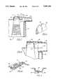
- FIG. 1shows an arch shape conduit of the prior art.
- FIG. 2is a side view of the device of FIG. 1.
- FIG. 3shows two interconnected units of the present invention.
- FIG. 4shows a sub-arch at a valley corrugation end, with a closed end spaced apart from the adjacent peak corrugation.
- FIG. 5shows a web connecting a sub-arch to the web of the adjacent corrugation peak.
- FIG. 6is a side view of the device of FIG. 4.
- FIG. 7shows a longtitudinal plane cross section of a conduit like those Of FIG. 4-6, where the end closure of FIG. 11 is in place and a sewer pipe connected into the receptacle formed by the end closure and sub-arch.
- FIG. 8shows the opposing ends of two conduits as they are being proximately mated, with a cantilever leg on the overlapped conduit end.
- FIG. 9is similar to FIG. 8 except that the conduits are mated.
- FIG. 10is a cross section of the mated conduit joint of FIG. 9.
- FIG. 11shows an end closure for a conduit.
- FIG. 12shows a sub-arch having a closed end which is a portion of the web of the adjacent peak corrugation.
- FIG. 13shows a structure connecting a cantilever leg to a sub-arch.
- FIG. 14shows a cantilever leg extending from the interior of the arch of an overlapping end, as it mates with the overlapped end of a mating conduit.
- the preferred embodiment of the inventionis described in terms of an arch shape conduit which is described and shown in the aforementioned U.S. Pat. No. 4,759,661, hereby incorporated by reference.
- the present inventionwill be also useful with other particular configurations of conduit. It will be generally useful for arch-shaped conduits suited for burial and interconnection within the earth.
- FIG. 1shows a fragment of the prior art device.
- FIG. 2shows the same device in a side view.
- the conduit 20is in the shape of an inverted trough. It has a top 18 when put in its working position and flanged base parts 22, 22'. There are a multiplicity of slots 24 or other kinds of perforations through the side walls 26.
- the conduithas corrugations along its length, running transverse to its length. The corrugations are comprised of alternating raised peaks 28 and depressed valleys 30.
- the two ends of the unitare valleys and are respectively overlapping and overlapped. The ends are adapted to shiplap corresponding overlapped and overlapping ends of adjoining like units. If cut in two, the opposing ends of a single conduit would mate with each other.
- the overlapped end 38is shown. It is characterized by the overlapped flange part 32 of the end valley 34.
- the overlapped flange partslips inside a mating part's overlapping valley end, as illustrated by FIG. 3.
- a sub-arch 36which is essentially a semi-circle, and has its own overlapped shiplap flange part 41.
- This sub-arch portionforms part of a circular sewer pipe receptacle when the end 38 is mated with a suitable closure 40, such as shown in FIG. 11, having a semi-circular cut out 42.
- the top of the sub-archis such that the sewer pipe top will be nominally level with the top of the adjacent peak corrugation.
- FIG. 3shows how two like units of the present invention interconnect.
- the conduitshave parts corresponding to those just described.
- FIG. 4-6correspond with FIG. 1 and 2, and show the improved sub-arch construction on the overlapped end of conduit 20a. Parts of the conduit 20a correspond with those just described for the conduit 20; they are numbered similarly but with a suffix. As FIG. 4 and 6 show the web 44 of the peak corrugation 28a adjacent the valley end is made continuous.
- the sub-arch 36ais spaced apart from the peak corrugation 28a and has a closed end 45.
- FIG. 5shows a small sub-arch web 37, which runs lengthwise along the conduit, connecting the corrugation peak web with the end 45b of the sub-arch 36b, thus providing further stiffness.
- FIG. 12shows in cross section another sub-arch construction which carries out the purpose of the invention.
- the sub-arch 72runs along the top of the valley corrugation (indicated by the dashed lines 78) to the web 76 of the adjacent peak corrugation 70; the web acts as the closure of the sub-arch.
- a sewer pipe 74is shown in the receptacle formed by the arch end closure 40 and the sub-arch 72.
- FIG. 7shows a lengthwise centerplane cross section of a conduit 72 having a sub-arch 36b and a sub-arch web 37c. It also has a double walled end closure 40, hike that shown in FIG. 11.
- a sewer pipe pipe 46is shown slipped into the circular cavity formed by the semi-circle of the subarch 36c and the semi-circle 42 of the closure. Also shown is a portion of an egg-crate like webbing 79, interior of the peak corrugation 41, to further provide for transfer of loading in the structure.
- FIG. 8-10 and FIG. 4show cantilever legs which cooperate with the shiplap joints of mating conduits.
- the leg 48has an E-shape cross section when viewed from the end of the conduit, being comprised of three webs and a connecting plate. This configuration is preferred for strength and injection molding; other leg configurations may be chosen. As will be seen, multiple legs, equally divided between each side of the arch are preferred, even though most of the description here is in term of one leg only.
- FIG. 8shows how an overlapped valley end 38c with a mating overlapping valley end 52 positioned for engagement.
- FIG. 9shows the same parts in engagement.
- FIG. 10shows a cross section through the mated joint of FIG. 9.
- the overlapped end 38chas a flange 32c which is adapted to be shiplapped by the overlapping valley 50 of the opposing end 52 of a mating unit.
- the leg 48extends along the conduit length. It crosses the overlapped end valley 34c and ties into the web 44c of the peak corrugation for strength. When conduits are mated, the leg 48 overlays and engages the exterior surface of the valley 50 of the overlapping end 52, capturing it in a female pocket 55.
- the female pocketsmay be visualized from FIG. 8 and 10 as being segments of the hypothetical annular female space defined by the bottom contour of the leg 48 surfaces and the upper surface of the flange 32c.
- the overlapped flange 32cis discontinuous or absent in the immediate vicinity of the leg 48. Doing this increases the fabricability of the design while still carrying out the essential principle of the invention.
- reference herein to a female pocket like spacewill be understood to include within such a configuration wherein the legs are, as in FIG. 8, offset with respect to the parts of the discontinuous flange and there is no literal pocket.
- a leg 82may also be used on the overlapping end 80 of a conduit as shown in FIG. 14.
- the legwill be on the interior or underside of the end of the conduit.
- An overlapped end 84 of a mating conduitis shown in the Figure, in the cavity.
- FIG. 3shows in side view two conduits 54, 56 mated together as they will be when buried in the earth to disperse or collect liquids, with the best combination of features. They are held together by a small molded locking tang in the overlapped part which elastically engages a detent in the mating part, and screws and rivets may be used as well.
- the arch shapeis preferrably a flattened arch.
- Conduit 54is the overlapped unit of the two.
- the dotted line 60indicates the extension of the overlapped flange of conduit 54 which is captured within the valley end 61 of the overlapping conduit 56. Of course, the overlapping is important to keep dirt and the like from entering the unit.
- Two legs 58are visible in FIG.
- the legswill best be placed near the upper or top portion of the valley arch of the overlapped conduit 54. As shown, the legs preferably will extend lengthwise the same distance as the amount of overlap.
- the web structures 64, 90are shown in more detail in the fragment of conduit 54 shown in FIG. 13. Web 90 interconnects the sub-arch to the adjacent leg. Web 64 connects the sub-arch to the peak corrugation 66.
- FIG. 15shows a further embodiment of a sub-arch 100 mounted on the valley 102 at the end of a conduit 104.
- the sub-archinstersects the web 106 of the peak corrugation 104.
- the webis discontinuous at hole 108, to enable liquid to enter the conduit from the sub-arch.
- the valleyis continuous in the region of the sub-arch, by virtue of the portion 110 which forms the bottom of the sub-arch.
- this embodimentcan be used in combination with the legs as was described for other embodiments.
Landscapes
- Engineering & Computer Science (AREA)
- General Engineering & Computer Science (AREA)
- Hydrology & Water Resources (AREA)
- Health & Medical Sciences (AREA)
- Public Health (AREA)
- Water Supply & Treatment (AREA)
- Life Sciences & Earth Sciences (AREA)
- Mechanical Engineering (AREA)
- Civil Engineering (AREA)
- Structural Engineering (AREA)
- Rigid Pipes And Flexible Pipes (AREA)
- Laying Of Electric Cables Or Lines Outside (AREA)
- Joints Allowing Movement (AREA)
Abstract
Description
Claims (18)
Priority Applications (1)
| Application Number | Priority Date | Filing Date | Title |
|---|---|---|---|
| US08/223,174US5401116A (en) | 1989-04-24 | 1994-04-05 | Leaching system conduit with cantilevered leg joint |
Applications Claiming Priority (4)
| Application Number | Priority Date | Filing Date | Title |
|---|---|---|---|
| US07/341,902US5017041A (en) | 1989-04-24 | 1989-04-24 | Leaching system conduit with high rigidity joint |
| US69488091A | 1991-05-02 | 1991-05-02 | |
| US07/893,555US5336017A (en) | 1989-04-24 | 1992-06-03 | Leaching system conduit with interlocking end joint |
| US08/223,174US5401116A (en) | 1989-04-24 | 1994-04-05 | Leaching system conduit with cantilevered leg joint |
Related Parent Applications (1)
| Application Number | Title | Priority Date | Filing Date |
|---|---|---|---|
| US07/893,555ContinuationUS5336017A (en) | 1989-04-24 | 1992-06-03 | Leaching system conduit with interlocking end joint |
Publications (1)
| Publication Number | Publication Date |
|---|---|
| US5401116Atrue US5401116A (en) | 1995-03-28 |
Family
ID=23339485
Family Applications (3)
| Application Number | Title | Priority Date | Filing Date |
|---|---|---|---|
| US07/341,902Expired - LifetimeUS5017041A (en) | 1989-04-24 | 1989-04-24 | Leaching system conduit with high rigidity joint |
| US07/893,555Expired - LifetimeUS5336017A (en) | 1989-04-24 | 1992-06-03 | Leaching system conduit with interlocking end joint |
| US08/223,174Expired - LifetimeUS5401116A (en) | 1989-04-24 | 1994-04-05 | Leaching system conduit with cantilevered leg joint |
Family Applications Before (2)
| Application Number | Title | Priority Date | Filing Date |
|---|---|---|---|
| US07/341,902Expired - LifetimeUS5017041A (en) | 1989-04-24 | 1989-04-24 | Leaching system conduit with high rigidity joint |
| US07/893,555Expired - LifetimeUS5336017A (en) | 1989-04-24 | 1992-06-03 | Leaching system conduit with interlocking end joint |
Country Status (2)
| Country | Link |
|---|---|
| US (3) | US5017041A (en) |
| CA (1) | CA2004564C (en) |
Cited By (29)
| Publication number | Priority date | Publication date | Assignee | Title |
|---|---|---|---|---|
| EP0780524A1 (en) | 1995-12-21 | 1997-06-25 | Infiltrator Systems, Inc. | Storm water dispersing system having multiple arches |
| USD403047S (en) | 1997-01-16 | 1998-12-22 | Gray Terrance H | Post and dome interconnect for leaching chambers |
| WO2001071112A1 (en) | 2000-03-17 | 2001-09-27 | Zoeller Company | Effluent distribution system |
| US6361248B1 (en) | 2000-08-25 | 2002-03-26 | Robert M. Maestro | Stormwater dispensing chamber |
| US20030219310A1 (en)* | 2002-05-20 | 2003-11-27 | Burnes James J. | Leaching chambers joined together with swivel connections |
| US6698975B1 (en) | 2002-08-27 | 2004-03-02 | Hancor, Inc. | Coupling structure for a leaching chamber |
| US6991402B2 (en) | 2002-10-17 | 2006-01-31 | Stormtrap Llc | Methods and modules for an underground assembly for storm water retention or detention |
| US7118306B2 (en)* | 2000-05-05 | 2006-10-10 | Infiltrator Systems, Inc | Stormwater management system |
| US20070071555A1 (en)* | 2005-09-26 | 2007-03-29 | Frank Currivan | Septic system |
| US20070071556A1 (en)* | 2005-09-26 | 2007-03-29 | Frank Currivan | Septic system |
| US7306400B1 (en) | 2003-10-01 | 2007-12-11 | Infiltrator Systems, Inc | Leaching chamber having dosing pipe hanger |
| US20070292210A1 (en)* | 2005-09-26 | 2007-12-20 | Frank Currivan | Septic system |
| US20080240859A1 (en)* | 2007-03-29 | 2008-10-02 | Rehbein Environmental Solutions, Inc. | Subsurface fluid distribution apparatus |
| US20090067928A1 (en)* | 2005-09-26 | 2009-03-12 | Frank Currivan | Septic system |
| US20090194473A1 (en)* | 2008-02-04 | 2009-08-06 | Brooks William R | Pipe stand |
| US20090220302A1 (en)* | 2008-02-13 | 2009-09-03 | Cobb Daniel P | Plastic detention chamber for stormwater runoff and related system and methods |
| US20100059430A1 (en)* | 2008-09-11 | 2010-03-11 | Adams David R | Stormwater chamber detention system |
| USD617867S1 (en) | 2009-03-05 | 2010-06-15 | Stormtrap Llc | Module for an underground assembly for storm water retention or detention |
| US20100226721A1 (en)* | 2009-03-05 | 2010-09-09 | Justin Ivan May | Module and Assembly for Managing the Flow of Water |
| US8636444B2 (en) | 2005-09-26 | 2014-01-28 | Frank Currivan | Fluid distribution system |
| US9273456B1 (en) | 2014-09-18 | 2016-03-01 | Winferd R. Miles | Leaching tube |
| US11186979B2 (en) | 2018-12-14 | 2021-11-30 | Stormtrap Llc | Module and assembly for underground management of fluids for shallow-depth applications |
| US11536017B2 (en) | 2016-10-26 | 2022-12-27 | Envirokeeper, LLC | Modular precast concrete water storage device and system |
| US11795679B2 (en) | 2021-07-19 | 2023-10-24 | Prinsco, Inc. | Asymmetric leaching chamber for onsite wastewater management system |
| US11879246B2 (en) | 2009-03-05 | 2024-01-23 | Stormtrap Llc | Module and method for managing water and other fluids |
| US20240228345A1 (en)* | 2021-05-01 | 2024-07-11 | Rhizoscape Technologies Pty Ltd | In Situ Fluid Diffusion Apparatus and System |
| USD1036616S1 (en) | 2022-02-17 | 2024-07-23 | Prinsco, Inc. | Septic chamber |
| USD1036617S1 (en) | 2022-02-17 | 2024-07-23 | Prinsco, Inc. | Septic chamber end cap |
| USD1053304S1 (en) | 2022-02-17 | 2024-12-03 | Prinsco, Inc. | Septic chamber |
Families Citing this family (30)
| Publication number | Priority date | Publication date | Assignee | Title |
|---|---|---|---|---|
| US5156488A (en)* | 1989-04-24 | 1992-10-20 | Infiltrator Systems, Inc. | Leaching system conduit with sub-arch |
| US5017041A (en)* | 1989-04-24 | 1991-05-21 | Infiltrator Systems Inc. | Leaching system conduit with high rigidity joint |
| USD329684S (en) | 1989-06-23 | 1992-09-22 | Gray Terrance H | Leaching chamber |
| US5556231A (en)* | 1994-09-01 | 1996-09-17 | Hancor, Inc. | Severable leaching chamber with end cap |
| US5669733A (en)* | 1994-09-01 | 1997-09-23 | Hancor, Inc. | Angled adapter for a leaching chamber system |
| US5511903A (en) | 1994-10-03 | 1996-04-30 | Infiltrator Systems, Inc. | Leaching chamber with perforated web sidewall |
| US5839844A (en)* | 1995-06-12 | 1998-11-24 | Infiltrator Systems, Inc. | Leaching chamber endplate |
| US6076993A (en) | 1997-06-16 | 2000-06-20 | Psa, Inc. | Leaching chamber |
| USD397090S (en) | 1996-03-11 | 1998-08-18 | Gray Terrance H | Coupling flange for conduits |
| US5921711A (en)* | 1997-01-23 | 1999-07-13 | Sipaila; Jonas Z. | Subsurface fluid distribution apparatus and method |
| JP2002538961A (en)* | 1999-03-17 | 2002-11-19 | ポッツ、デビッド、エイ. | Method and apparatus for leaching area treatment |
| US6602023B2 (en) | 1999-12-22 | 2003-08-05 | Infiltrator Systems, Inc. | Leaching chamber endplate |
| US7052209B1 (en)* | 2000-05-05 | 2006-05-30 | Infiltrator Systems, Inc. | Corrugated stormwater chamber |
| US7500805B1 (en) | 2003-10-01 | 2009-03-10 | Brochu Ronald P | Low-nest height thermoplastic leaching chamber |
| US7311467B2 (en)* | 2003-10-01 | 2007-12-25 | Infiltrator Systems, Inc. | Ergonomic size leaching chamber |
| US7237981B1 (en)* | 2004-01-08 | 2007-07-03 | Stormtech, Llc | End cap having integral pipe stub for use with stormwater chamber |
| USD538387S1 (en)* | 2005-07-01 | 2007-03-13 | Hancor, Inc. | Set of leaching chamber end units |
| US7364384B1 (en)* | 2005-07-27 | 2008-04-29 | Infiltrator Systems, Inc. | Anti-rotation stop for chamber |
| US7287932B2 (en)* | 2005-08-22 | 2007-10-30 | The English Oak Partnership, L.P. | Ballasting system for on-site sewage treatment and disposal system |
| US7273330B1 (en) | 2005-11-16 | 2007-09-25 | Infiltrator Systems, Inc. | Invert elevation-change adapter |
| US9255394B2 (en) | 2009-06-05 | 2016-02-09 | Stormtech Llc | Corrugated stormwater chamber having sub-corrugations |
| US8672583B1 (en) | 2009-06-05 | 2014-03-18 | Stormtech Llc | Corrugated stormwater chamber having sub-corrugations |
| US7914230B2 (en)* | 2009-06-29 | 2011-03-29 | Infiltrator Systems, Inc. | Corrugated leaching chamber with hollow pillar supports |
| US20160116112A1 (en)* | 2014-10-23 | 2016-04-28 | Anchor Concrete Products Ltd. | Modular Assembly For Fabricating A Hollow Structure |
| US10413126B2 (en) | 2017-02-27 | 2019-09-17 | Donald J. Hudepohl | Upturned protruding overspill shield |
| WO2020023970A1 (en) | 2018-07-27 | 2020-01-30 | Advanced Drainage Systems, Inc. | End caps for stormwater chambers and methods of making same |
| US11028570B2 (en) | 2018-10-30 | 2021-06-08 | Advanced Drainage Systems, Inc. | Systems, apparatus, and methods for maintenance of stormwater management systems |
| US11028569B2 (en)* | 2018-10-30 | 2021-06-08 | Advanced Drainage Systems, Inc. | Systems, apparatus, and methods for maintenance of stormwater management systems |
| US11732457B2 (en)* | 2021-08-31 | 2023-08-22 | Geldenhuis Pieter | Water infiltration conduit |
| US12352032B2 (en) | 2022-04-15 | 2025-07-08 | Eljen Corporation | Chamber for subsoil fluid treatment |
Citations (18)
| Publication number | Priority date | Publication date | Assignee | Title |
|---|---|---|---|---|
| US460352A (en)* | 1891-09-29 | Drain-tile | ||
| US680548A (en)* | 1901-05-08 | 1901-08-13 | James Frederic Sikes | Drain. |
| US2153789A (en)* | 1937-11-13 | 1939-04-11 | Firman L Carswell | Irrigation and drainage tube |
| US2366522A (en)* | 1942-11-10 | 1945-01-02 | Maurice R Gutman | Unit for drainage systems |
| US2866319A (en)* | 1954-09-07 | 1958-12-30 | Edward P Nicholson | Drainage assembly |
| US3333422A (en)* | 1965-08-30 | 1967-08-01 | William M Neyland | Subirrigation conduit |
| US3440823A (en)* | 1967-06-14 | 1969-04-29 | John H Olsen | Drainage device |
| US3495410A (en)* | 1966-11-14 | 1970-02-17 | Walter A Bailey | Corrugated half tile and method of making same |
| US3570251A (en)* | 1969-01-08 | 1971-03-16 | Dennis G Roberts | Drainage tile |
| US3579995A (en)* | 1969-06-10 | 1971-05-25 | John F Flynn | Vented leaching channel |
| US3645100A (en)* | 1970-01-16 | 1972-02-29 | Rotondo & Sons Inc A | Leaching chamber unit for soil absorption system |
| US3962088A (en)* | 1974-09-17 | 1976-06-08 | Elberfeld Concrete Block Co., Inc. (Entire) | Concrete block assembly |
| US4183696A (en)* | 1976-05-03 | 1980-01-15 | Auriemma Robert S | Underground drainage pipe |
| US4245924A (en)* | 1978-12-07 | 1981-01-20 | Hancor, Inc. | Arch conduit |
| US4523613A (en)* | 1980-07-01 | 1985-06-18 | Hancor, Inc. | Multi-layered corrugated conduit with "black-eye" like apertures |
| US4588325A (en)* | 1984-07-26 | 1986-05-13 | Seefert Kenneth F | Modular rock replacing drain field apparatus |
| US4759661A (en)* | 1987-02-27 | 1988-07-26 | Infiltrator Systems Inc | Leaching system conduit |
| US5087151A (en)* | 1989-01-30 | 1992-02-11 | Ditullio Robert J | Drainage system |
Family Cites Families (5)
| Publication number | Priority date | Publication date | Assignee | Title |
|---|---|---|---|---|
| US980442A (en)* | 1910-01-04 | 1911-01-03 | Canton Culvert Company | Draining-culvert. |
| US1541918A (en)* | 1923-04-27 | 1925-06-16 | John W Brennan | Drainage tile |
| US4360042A (en)* | 1978-12-07 | 1982-11-23 | Hancor, Inc. | Arched conduit with improved corrugations |
| EP0217055B1 (en)* | 1985-07-31 | 1991-01-09 | Kawasumi Laboratories, Inc. | A connector for plasmapheresis bag |
| US5017041A (en)* | 1989-04-24 | 1991-05-21 | Infiltrator Systems Inc. | Leaching system conduit with high rigidity joint |
- 1989
- 1989-04-24USUS07/341,902patent/US5017041A/ennot_activeExpired - Lifetime
- 1989-11-28CACA002004564Apatent/CA2004564C/ennot_activeExpired - Fee Related
- 1992
- 1992-06-03USUS07/893,555patent/US5336017A/ennot_activeExpired - Lifetime
- 1994
- 1994-04-05USUS08/223,174patent/US5401116A/ennot_activeExpired - Lifetime
Patent Citations (18)
| Publication number | Priority date | Publication date | Assignee | Title |
|---|---|---|---|---|
| US460352A (en)* | 1891-09-29 | Drain-tile | ||
| US680548A (en)* | 1901-05-08 | 1901-08-13 | James Frederic Sikes | Drain. |
| US2153789A (en)* | 1937-11-13 | 1939-04-11 | Firman L Carswell | Irrigation and drainage tube |
| US2366522A (en)* | 1942-11-10 | 1945-01-02 | Maurice R Gutman | Unit for drainage systems |
| US2866319A (en)* | 1954-09-07 | 1958-12-30 | Edward P Nicholson | Drainage assembly |
| US3333422A (en)* | 1965-08-30 | 1967-08-01 | William M Neyland | Subirrigation conduit |
| US3495410A (en)* | 1966-11-14 | 1970-02-17 | Walter A Bailey | Corrugated half tile and method of making same |
| US3440823A (en)* | 1967-06-14 | 1969-04-29 | John H Olsen | Drainage device |
| US3570251A (en)* | 1969-01-08 | 1971-03-16 | Dennis G Roberts | Drainage tile |
| US3579995A (en)* | 1969-06-10 | 1971-05-25 | John F Flynn | Vented leaching channel |
| US3645100A (en)* | 1970-01-16 | 1972-02-29 | Rotondo & Sons Inc A | Leaching chamber unit for soil absorption system |
| US3962088A (en)* | 1974-09-17 | 1976-06-08 | Elberfeld Concrete Block Co., Inc. (Entire) | Concrete block assembly |
| US4183696A (en)* | 1976-05-03 | 1980-01-15 | Auriemma Robert S | Underground drainage pipe |
| US4245924A (en)* | 1978-12-07 | 1981-01-20 | Hancor, Inc. | Arch conduit |
| US4523613A (en)* | 1980-07-01 | 1985-06-18 | Hancor, Inc. | Multi-layered corrugated conduit with "black-eye" like apertures |
| US4588325A (en)* | 1984-07-26 | 1986-05-13 | Seefert Kenneth F | Modular rock replacing drain field apparatus |
| US4759661A (en)* | 1987-02-27 | 1988-07-26 | Infiltrator Systems Inc | Leaching system conduit |
| US5087151A (en)* | 1989-01-30 | 1992-02-11 | Ditullio Robert J | Drainage system |
Non-Patent Citations (1)
| Title |
|---|
| Pallet Crate Sketch; Unknown Author; Unknown Publication Date; (1) Page.* |
Cited By (49)
| Publication number | Priority date | Publication date | Assignee | Title |
|---|---|---|---|---|
| EP0780524A1 (en) | 1995-12-21 | 1997-06-25 | Infiltrator Systems, Inc. | Storm water dispersing system having multiple arches |
| USD403047S (en) | 1997-01-16 | 1998-12-22 | Gray Terrance H | Post and dome interconnect for leaching chambers |
| WO2001071112A1 (en) | 2000-03-17 | 2001-09-27 | Zoeller Company | Effluent distribution system |
| US6375388B1 (en) | 2000-03-17 | 2002-04-23 | Zoeller Company | Affluent distribution system capable of being horizontally offset or curved |
| US7118306B2 (en)* | 2000-05-05 | 2006-10-10 | Infiltrator Systems, Inc | Stormwater management system |
| US6361248B1 (en) | 2000-08-25 | 2002-03-26 | Robert M. Maestro | Stormwater dispensing chamber |
| US6612777B2 (en) | 2000-08-25 | 2003-09-02 | Robert M. Maestro | Stormwater dispensing chamber |
| US7351006B2 (en)* | 2002-05-20 | 2008-04-01 | Infiltrator Systems, Inc. | Leaching chambers joined together with swivel connections |
| US20030219310A1 (en)* | 2002-05-20 | 2003-11-27 | Burnes James J. | Leaching chambers joined together with swivel connections |
| US6698975B1 (en) | 2002-08-27 | 2004-03-02 | Hancor, Inc. | Coupling structure for a leaching chamber |
| US6991402B2 (en) | 2002-10-17 | 2006-01-31 | Stormtrap Llc | Methods and modules for an underground assembly for storm water retention or detention |
| US20060034662A1 (en)* | 2002-10-17 | 2006-02-16 | Burkhart Philip J | Methods and module for an underground assembly for storm water retention or detention |
| US7160058B2 (en) | 2002-10-17 | 2007-01-09 | Stormtrap Llc | Methods and module for an underground assembly for storm water retention or detention |
| US7344335B2 (en) | 2002-10-17 | 2008-03-18 | Stormtrap Llc | Methods and modules for an underground assembly for storm water retention or detention |
| US20070099477A1 (en)* | 2002-10-17 | 2007-05-03 | Burkhart Philip J | Methods and modules for an underground assembly for storm water retention or detention |
| US7306400B1 (en) | 2003-10-01 | 2007-12-11 | Infiltrator Systems, Inc | Leaching chamber having dosing pipe hanger |
| US20070292210A1 (en)* | 2005-09-26 | 2007-12-20 | Frank Currivan | Septic system |
| US20070071556A1 (en)* | 2005-09-26 | 2007-03-29 | Frank Currivan | Septic system |
| US8007201B2 (en) | 2005-09-26 | 2011-08-30 | Frank Currivan | Septic system |
| US7384212B2 (en) | 2005-09-26 | 2008-06-10 | Frank Currivan | Septic system |
| US20090067928A1 (en)* | 2005-09-26 | 2009-03-12 | Frank Currivan | Septic system |
| US20070071555A1 (en)* | 2005-09-26 | 2007-03-29 | Frank Currivan | Septic system |
| US8636444B2 (en) | 2005-09-26 | 2014-01-28 | Frank Currivan | Fluid distribution system |
| US20080240859A1 (en)* | 2007-03-29 | 2008-10-02 | Rehbein Environmental Solutions, Inc. | Subsurface fluid distribution apparatus |
| US7517172B2 (en)* | 2007-03-29 | 2009-04-14 | Rehbein Environmental Solutions, Inc. | Subsurface fluid distribution apparatus |
| US20090194473A1 (en)* | 2008-02-04 | 2009-08-06 | Brooks William R | Pipe stand |
| US8603332B2 (en) | 2008-02-04 | 2013-12-10 | William R. Brooks | Method of constructing septic system including pipe support |
| US20090220302A1 (en)* | 2008-02-13 | 2009-09-03 | Cobb Daniel P | Plastic detention chamber for stormwater runoff and related system and methods |
| US8491224B2 (en) | 2008-02-13 | 2013-07-23 | Contech Engineered Solutions LLC | Plastic detention chamber for stormwater runoff and related system and methods |
| US20100059430A1 (en)* | 2008-09-11 | 2010-03-11 | Adams David R | Stormwater chamber detention system |
| US8147688B2 (en) | 2008-09-11 | 2012-04-03 | Contech Engineered Solutions LLC | Stormwater chamber detention system |
| US10267028B2 (en) | 2009-03-05 | 2019-04-23 | Stormtrap Llc | Module and method for managing water and other fluids |
| US11879246B2 (en) | 2009-03-05 | 2024-01-23 | Stormtrap Llc | Module and method for managing water and other fluids |
| US8770890B2 (en) | 2009-03-05 | 2014-07-08 | Stormtrap Llc | Module and assembly for managing the flow of water |
| US9428880B2 (en) | 2009-03-05 | 2016-08-30 | Stormtrap Llc | Module and method for managing water and other fluids |
| US9464400B2 (en) | 2009-03-05 | 2016-10-11 | Stormtrap Llc | Assembly for the detention or retention of water and other fluids |
| US9951508B2 (en) | 2009-03-05 | 2018-04-24 | Stormtrap Llc | Assembly for detaining or retaining liquid beneath a ground surface |
| US20100226721A1 (en)* | 2009-03-05 | 2010-09-09 | Justin Ivan May | Module and Assembly for Managing the Flow of Water |
| US11186978B2 (en) | 2009-03-05 | 2021-11-30 | Stormtrap Llc | Module and method for managing water and other fluids |
| USD617867S1 (en) | 2009-03-05 | 2010-06-15 | Stormtrap Llc | Module for an underground assembly for storm water retention or detention |
| US9273456B1 (en) | 2014-09-18 | 2016-03-01 | Winferd R. Miles | Leaching tube |
| US11536017B2 (en) | 2016-10-26 | 2022-12-27 | Envirokeeper, LLC | Modular precast concrete water storage device and system |
| US11186979B2 (en) | 2018-12-14 | 2021-11-30 | Stormtrap Llc | Module and assembly for underground management of fluids for shallow-depth applications |
| US20240228345A1 (en)* | 2021-05-01 | 2024-07-11 | Rhizoscape Technologies Pty Ltd | In Situ Fluid Diffusion Apparatus and System |
| US12246976B2 (en)* | 2021-05-01 | 2025-03-11 | Rhizoscape Technologies Pty Ltd | In situ fluid diffusion apparatus and system |
| US11795679B2 (en) | 2021-07-19 | 2023-10-24 | Prinsco, Inc. | Asymmetric leaching chamber for onsite wastewater management system |
| USD1036616S1 (en) | 2022-02-17 | 2024-07-23 | Prinsco, Inc. | Septic chamber |
| USD1036617S1 (en) | 2022-02-17 | 2024-07-23 | Prinsco, Inc. | Septic chamber end cap |
| USD1053304S1 (en) | 2022-02-17 | 2024-12-03 | Prinsco, Inc. | Septic chamber |
Also Published As
| Publication number | Publication date |
|---|---|
| CA2004564A1 (en) | 1990-10-24 |
| CA2004564C (en) | 1995-09-26 |
| US5017041A (en) | 1991-05-21 |
| US5336017A (en) | 1994-08-09 |
Similar Documents
| Publication | Publication Date | Title |
|---|---|---|
| US5401116A (en) | Leaching system conduit with cantilevered leg joint | |
| US5156488A (en) | Leaching system conduit with sub-arch | |
| US4468910A (en) | Mat module with ramp strip | |
| US5511903A (en) | Leaching chamber with perforated web sidewall | |
| US5326191A (en) | Reinforced metal box culvert | |
| US5765323A (en) | Drainage pipe | |
| US10428510B1 (en) | Leaching unit having overhanging and perforated canopy | |
| JPH09279668A (en) | Assembly buried underground that receives and disperses water | |
| CA2535015C (en) | Faceted end cap for leaching chamber | |
| US9045873B1 (en) | Leaching chamber with water-permeable barriers on sidewalls | |
| US2866319A (en) | Drainage assembly | |
| US4145157A (en) | Modular drain field section | |
| EP0040621B1 (en) | An arrangement relating to a drainage pipe | |
| KR100222498B1 (en) | Pressure Spiral Wave Tube | |
| GB2109845A (en) | Drainage of highways | |
| US2737093A (en) | Sheet metal airfield deck mats | |
| US900039A (en) | Culvert. | |
| EP0297907A1 (en) | Plastics drainage pipe and manufacture thereof | |
| US5907875A (en) | Structural components of swimming pools | |
| JPH042224Y2 (en) | ||
| JPS5941220Y2 (en) | buried drain pipe | |
| JPS621318Y2 (en) | ||
| JPS6011992Y2 (en) | Concrete block for side ditch | |
| WO2025178686A1 (en) | Drainage body unit | |
| JP2507176Y2 (en) | Liquid tank |
Legal Events
| Date | Code | Title | Description |
|---|---|---|---|
| STCF | Information on status: patent grant | Free format text:PATENTED CASE | |
| AS | Assignment | Owner name:FLEET NATIONAL BANK, AS AGENT FOR FLEET NATIONAL B Free format text:ASSIGNMENT OF ASSIGNORS INTEREST;ASSIGNOR:FLEET BANK, N.A., AS AGENT FOR FLEET BANK, N.A. AND CITIZENS SAVINGS BANK;REEL/FRAME:008119/0952 Effective date:19960712 | |
| AS | Assignment | Owner name:FLEET NATIONAL BANK AS AGENT FOR FLEET NATIONAL BA Free format text:SECURITY INTEREST;ASSIGNOR:INFILTRATOR SYSTEMS, INC.;REEL/FRAME:008430/0810 Effective date:19970213 | |
| AS | Assignment | Owner name:FOOTHILL CAPITAL CORPORATION, CALIFORNIA Free format text:ASSIGNMENT OF ASSIGNORS INTEREST;ASSIGNOR:INFILTRATOR SYSTEMS, INC.;REEL/FRAME:009386/0986 Effective date:19980629 | |
| REMI | Maintenance fee reminder mailed | ||
| FPAY | Fee payment | Year of fee payment:4 | |
| SULP | Surcharge for late payment | ||
| FPAY | Fee payment | Year of fee payment:8 | |
| SULP | Surcharge for late payment | Year of fee payment:7 | |
| AS | Assignment | Owner name:MERRILL LYNCH CAPITAL, A DIVISION OF MERRILL LYNCH Free format text:SECURITY AGREEMENT;ASSIGNOR:INFILTRATOR SYSTEMS, INC.;REEL/FRAME:016621/0275 Effective date:20050929 | |
| AS | Assignment | Owner name:INFILTRATOR SYSTEMS, INC., CONNECTICUT Free format text:RELEASE OF SECURITY INTEREST IN PATENTS;ASSIGNOR:WELLS FARGO FOOTHILL, INC. (F/K/A FOOTHILL CAPITAL CORPORATION);REEL/FRAME:016630/0469 Effective date:20050928 | |
| FPAY | Fee payment | Year of fee payment:12 | |
| AS | Assignment | Owner name:MERRILL LYNCH CAPITAL, A DIVISION OF MERRILL LYNCH Free format text:SECURITY AGREEMENT;ASSIGNOR:INFILTRATOR SYSTEMS, INC.;REEL/FRAME:018463/0060 Effective date:20061031 | |
| AS | Assignment | Owner name:AMERICAN CAPITAL FINANCIAL SERVICES, INC., MARYLAN Free format text:SECURITY AGREEMENT;ASSIGNOR:INFILTRATOR SYSTEMS, INC;REEL/FRAME:018463/0693 Effective date:20061031 | |
| AS | Assignment | Owner name:AMERICAN CAPITAL FINANCIAL SERVICES, INC., MARYLAN Free format text:SECURITY AGREEMENT;ASSIGNOR:INFILTRATOR SYSTEMS, INC.;REEL/FRAME:021773/0179 Effective date:20081031 | |
| AS | Assignment | Owner name:INFILTRATOR SYSTEMS, INC., CONNECTICUT Free format text:RELEASE BY SECURED PARTY;ASSIGNOR:AMERICAN CAPITAL, LTD.;REEL/FRAME:035749/0405 Effective date:20150511 | |
| AS | Assignment | Owner name:INFILTRATOR SYSTEMS, INC. (FORMERLY KNOWN AS WATER Free format text:RELEASE BY SECURED PARTY;ASSIGNOR:GE BUSINESS FINANCIAL SERVICES, INC. (FORMERLY KNOWN AS MERRILL LYNCH CAPITAL, A DIVISION OF MERRILL LYNCH BUSINESS FINANCIAL SERVICES, INC.);REEL/FRAME:035745/0166 Effective date:20150528 Owner name:EZFLOW, L.P. (FORMERLY KNOWN AS RING INDUSTRIAL GR Free format text:RELEASE BY SECURED PARTY;ASSIGNOR:GE BUSINESS FINANCIAL SERVICES INC. (FORMERLY KNOWN AS MERRILL LYNCH BUSINESS FINANCIAL SERVICES INC.);REEL/FRAME:035797/0837 Effective date:20150528 Owner name:INFILTRATOR SYSTEMS, INC. (FORMERLY KNOWN AS WATER Free format text:RELEASE BY SECURED PARTY;ASSIGNOR:GE BUSINESS FINANCIAL SERVICES INC. (FORMERLY KNOWN AS MERRILL LYNCH BUSINESS FINANCIAL SERVICES INC.);REEL/FRAME:035797/0837 Effective date:20150528 |