US5401018A - Baseball simulation game - Google Patents
Baseball simulation gameDownload PDFInfo
- Publication number
- US5401018A US5401018AUS07/975,228US97522892AUS5401018AUS 5401018 AUS5401018 AUS 5401018AUS 97522892 AUS97522892 AUS 97522892AUS 5401018 AUS5401018 AUS 5401018A
- Authority
- US
- United States
- Prior art keywords
- ball
- simulated
- recited
- game
- baseball game
- Prior art date
- Legal status (The legal status is an assumption and is not a legal conclusion. Google has not performed a legal analysis and makes no representation as to the accuracy of the status listed.)
- Expired - Lifetime
Links
- 238000004088simulationMethods0.000titledescription13
- 230000000007visual effectEffects0.000claimsabstractdescription12
- 238000000034methodMethods0.000claimsdescription28
- 238000001514detection methodMethods0.000claimsdescription3
- 230000003287optical effectEffects0.000claimsdescription3
- 238000010586diagramMethods0.000description4
- 239000000725suspensionSubstances0.000description4
- 230000000712assemblyEffects0.000description3
- 238000000429assemblyMethods0.000description3
- 230000008569processEffects0.000description3
- 230000004075alterationEffects0.000description2
- 230000008878couplingEffects0.000description2
- 238000010168coupling processMethods0.000description2
- 238000005859coupling reactionMethods0.000description2
- 230000000694effectsEffects0.000description2
- 230000004048modificationEffects0.000description2
- 238000012986modificationMethods0.000description2
- 230000000284resting effectEffects0.000description2
- 206010048909BoredomDiseases0.000description1
- 206010045453Umbilical cord shortDiseases0.000description1
- 230000009471actionEffects0.000description1
- 230000003044adaptive effectEffects0.000description1
- 239000000872bufferSubstances0.000description1
- 238000004364calculation methodMethods0.000description1
- 239000004744fabricSubstances0.000description1
- 230000006870functionEffects0.000description1
- 230000005484gravityEffects0.000description1
- 239000000463materialSubstances0.000description1
- 239000002184metalSubstances0.000description1
- NJPPVKZQTLUDBO-UHFFFAOYSA-NnovaluronChemical compoundC1=C(Cl)C(OC(F)(F)C(OC(F)(F)F)F)=CC=C1NC(=O)NC(=O)C1=C(F)C=CC=C1FNJPPVKZQTLUDBO-UHFFFAOYSA-N0.000description1
- 230000002093peripheral effectEffects0.000description1
- 239000011295pitchSubstances0.000description1
- 239000012858resilient materialSubstances0.000description1
- 230000035939shockEffects0.000description1
- 238000009491sluggingMethods0.000description1
Images


Classifications
- A—HUMAN NECESSITIES
- A63—SPORTS; GAMES; AMUSEMENTS
- A63B—APPARATUS FOR PHYSICAL TRAINING, GYMNASTICS, SWIMMING, CLIMBING, OR FENCING; BALL GAMES; TRAINING EQUIPMENT
- A63B63/00—Targets or goals for ball games
- A—HUMAN NECESSITIES
- A63—SPORTS; GAMES; AMUSEMENTS
- A63B—APPARATUS FOR PHYSICAL TRAINING, GYMNASTICS, SWIMMING, CLIMBING, OR FENCING; BALL GAMES; TRAINING EQUIPMENT
- A63B69/00—Training appliances or apparatus for special sports
- A63B69/0002—Training appliances or apparatus for special sports for baseball
Definitions
- This inventionrelates to arcade games and more particularly to game simulators.
- Game practice and game simulation apparatusare well-known in the gaming industry. For example, there are a great many machines which will allow a user to practice golf or baseball skills, or to play a simulated golf game.
- Game simulationsallow a player to experience game action or to improve his or her skill in a game more conveniently and in less time than when playing a real game.
- Baseball game practice apparatususually include a ball and a playing area to hit the ball into with a club or bat, and often also include a method to determine how well a player hit the ball.
- A. Ratajacdescribes a collapsible, portable batting cage in which a ball is suspended at an adjustable hitting position by four shock cords attached to the cage frame. The ball is hit by a player into a net stretched across the rear of the cage frame.
- J. DePernadescribes a baseball game in which a pitcher player pitches a ball at a batting player, who hits the ball into a number of ball sensing field zones facing the batter.
- the type of hitcan be designated a hit, foul, or out from the location of the sensing zone that the ball penetrated and the mount of time the ball took to reach the sensing zone.
- R. Beardescribes an adaptive sports training system in which a ball is delivered to and hit by a player at a target grid, which evaluates the skill of the hit and modifies the skill level of the game accordingly.
- the present inventionprovides an apparatus and method to play a simulated baseball game. This is accomplished, in part, by accurately determining the velocity of a hit ball, i.e. both the speed and direction of the ball. In this way, the apparatus of the present invention is much more than a baseball practice game: it becomes an accurate baseball simulator machine. These features add excitement and complexity to the game, which tends to prolong player involvement.
- the baseball simulator of the present inventioncomprises a wailed frame inside which a ball is suspended in front of the player by cords or a similar supporting structure.
- the suspended ballfaces a detector assembly comprising an x-y sensing grid.
- a playerhits the ball with a bat towards the detector assembly, which detects the coordinates of the ball as it impinges upon the detection assembly.
- the ballthen returns to its initial position due to the elasticity of the support cords.
- the initial velocity and a simulated trajectory of the ballare accurately calculated by a digital computer.
- the computercalculates velocity from speed and direction information received from the game's sensors.
- the speedis determined by dividing the distance the ball travelled by the time the ball took to travel from its initial position to the detector assembly.
- the timeis measured by starting a timer when the ball is first hit and stopping the timer when the ball reaches the detector assembly.
- the timeris connected to a support cord attached to the ball so that when the ball initially moves, the timer is activated.
- the computercalculates the direction of the ball by using a formula requiring the coordinates of the initial position and the final position of the ball.
- the initial positionis a known constant, and the final position is detected by the detector assembly.
- the computercan calculate a simulated trajectory of the ball with a high degree of accuracy.
- the computeralso determines whether any simulated fielding players are able to catch the ball and if the hit is an out, a foul, or a scoring/base hit.
- a score displayis adjusted accordingly, and audio and visual feedback is provided according to the result of the hit.
- a variation of the simulator gameadds an award dispensed to the player according to the result of the game.
- the game simulatoradds accuracy to the simulation of the trajectory of the hit ball, creating a more realistic game. With such accurate simulations, player interest is heightened and the challenge to the player is significantly increased.
- the audio and visual feedbackprovide a player with a game atmosphere and add interest to the game as well, increasing the revenue produced by the game.
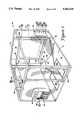
- FIG. 1is a perspective view of the simulation game unit in accordance with the present invention.
- FIG. 2is a perspective view of a player playing the simulation game unit
- FIG. 3is a schematic top plan view of the game simulation unit
- FIG. 4is a detail view of the spring/timing means connected to the frame and the support means;
- FIG. 5is a front view of the detector assembly, ball, and ball support
- FIG. 6is a detail view of the coin box of the game unit
- FIG. 7is a block diagram of the computer control system for a simulator game unit of the present invention.
- FIG. 8is a flow diagram of the process of simulating the game of the present invention.
- a game simulator unit 10in accordance with the present invention includes a frame 12 defining a batting cage 13, a ball 14, support assembly 16, detector assembly 20, a digital computer 22, feedback assemblies 23a and 23b, a display 24, a coin box 26, and a control panel 27.
- one playerplays the game at a single time by standing within batting cage 13 in batting box 15a or 15b depending upon whether they are right or left handed, respectively.
- Alternate embodimentscan permit more players to play at one time by permitting players to take turns hitting the ball, etc.
- Frame 12is preferably a metal, rectangular prism defining the batting cage 13.
- a door 28 in frame 12permits player entry and exit from the batting cage 13.
- Fencing material 30is supported by the frame 12 so that outside onlookers are protected from balls hit by the player and from the swinging bat.
- Ball 14is suspended near the center of the batting cage 13.
- the ballis typically a baseball or softball, but it can also be any suitable object for being hit by a player.
- the ball 14is suspended by support assembly 16, which holds the ball 14 in a known initial position and returns the ball to that initial position after the ball has been hit.
- the support assembly 16includes cords or other flexible cables that can hold the ball 14 in the known, initial position.
- the support means 16can also comprise other embodiments, such as a pedestal that holds the ball 14 at a specific height, a support beam projecting from the frame 12, or a similar structure that holds the ball 14 at a known initial position and returns the ball to that initial position.
- the support assembly 16is secured to the ball 14 preferably by passing a support cord through a hole in the ball and securing the ball to the cord with fasteners. Other devices can also be used that secure the ball 14 to the support assembly 16 securely enough so that the ball can be hit with a bat and remain connected to the support assembly 16.
- the support assembly 16 in the preferred embodimentincludes a ball suspension cord 32 which extends upwardly from the ball 14 towards a support beam 34 of frame 12, passes through an eyelet 35, and extends horizontally to the back end of the frame 12 where it is anchored by sensing assembly 18.
- Two guide tethers 36are connected to the ball 14 by a short cord 36a and to the floor 37 of the game unit 10. The ball suspension cord 32 and the two guide tethers 36 stabilize the ball 14 and hold the ball 14 at a known initial position.
- the vertical cord 32is an elastic or "bungee" cord operative to bring the ball 14 back to its initial position if the ball is hit, and the guide ropes 36 prevent the ball 14 from being hit too far to the right or the left and stop the ball after it has recoiled from hitting detector assembly 20.
- a sensing assembly 18is located at the back end of the frame 12 and is coupled to the ball suspension cord 32.
- the sensing assembly 18starts the timer that measures the time of the ball's flight.
- the sensing assembly 18is detailed subsequently with reference to FIG. 4.
- Detector assembly 20is spaced from the ball 14 by about three feet.
- detector assembly 20includes a screen 39 and an x-y grid of sensors located in front of the screen.
- the detector assembly 20is positioned so that a player hits the ball towards the screen 39, and the ball's final position is detected by the sensor grid before or as the ball 14 collides with the screen 39.
- the detector assemblypreferably detects the cartesian coordinates of the ball 14 and also stops the timer. The coordinates and elapsed time are used by the computer to calculate the velocity and a simulated trajectory of the ball (described below). The detector assembly is more fully described with reference to FIG. 5.
- Digital computer 22receives information sent to it by the sensor grid and timer.
- the computeris preferably a microprocessor-controlled digital apparatus with several input/output ports.
- the computerincludes six input/output ports A, B, C, D, E, and F, coupled to input/output (I/O) devices of the game unit by lines, cables, or busses.
- the I/O devicesinclude detector assembly 20, sensing assembly 18, feedback assemblies 23a and 23b, display 24, coin box 26, and control panel 27.
- the computer system 22is described in greater detail with reference to FIG. 7.
- Feedback assemblies 23a and 23boutput audio and (optionally) visual feedback, respectively, to the player based upon the calculated result of the hit.
- the feedback assembly 23aincludes a speaker, which outputs audio sound effects and announcer voices to the player during the game.
- the computer 22controls the sound effects by sending signals from an output port E on cable 38 to the speaker 23a.
- Feedback assembly 23bincludes a video screen that can display computer-controlled graphical images based on the hit result.
- Video screen 23bis coupled to output port F on the computer 22 by cable 41.
- Computer 22sends video signals on cable 41 that display animated graphics images on the screen 23b.
- Such imagesinclude a baseball playing field, a ball in flight, fielding players, a pitcher, base runners, a crowd, etc.
- the imagesare computer animated or stored on videodisc by techniques well-known in the art.
- feedback assembly 23bincludes a projector located in front of screen 39. The projector is operative to project graphical images onto screen 39 from the front and is controlled by computer 22 similarly to the video screen described above.
- Display 24is placed on the inside of the frame 12 to facilitate easy viewing by the player and is preferably an LED or LCD display coupled to output port B of the digital computer 22 by a bus 25.
- the display 24shows game status information and score.
- the displayshows the number of runs scored by one or two players, the number of fouls and outs currently accumulated, and the current inning number.
- the displaycan also show team names, player names, player statistics, inning scores, advertisements, or other information normally displayed at a baseball game.
- Coin box 26is located outside the batting cage 13 and is coupled to port A of the computer 22 by a bus 29. Players preferably insert a coin or token to play the game before entering the batting cage 13. Coin box 26 is described in greater detail with reference to FIG. 6.
- Control panel 27is preferably located adjacent to the coin box 26. Panel 27 is coupled to I/O port A of computer 22 by the same bus 29 that couples the coin box 26 to computer 22. Panel 27 includes controls for the player to select different parameters in the game, such as skill level, opponent team, team names, player alias, ballpark name and look, and ball height from the ground. Preferably, these controls are activated by the player after inserting a coin into the coin box 26 and prior to entering the batting cage 13.
- FIG. 2is a perspective view of game simulation unit 10 with a player standing within the batting cage 13.
- the playeris standing in the batting box 15a adjacent a plate 40 as in a normal game of baseball.
- the ball 14is hit with a bat 42 so that the ball flies toward detector assembly 20.
- Support means 16returns the ball 14 back to its initial, resting position. The player can then hit the ball again if the game has not ended.
- bat 42is connected to frame 12 by a chain or the like (not shown) to prevent the bat from being removed from the batting cage 13.
- FIG. 3shows a schematic, top plan view of the game simulation unit 10.
- the initial position of the ball 14is preferably directly under the support beam 34.
- Field perimeter lines 44define the area where the ball 14 may be hit by the player; preferably, side tethers 36 prevent the ball 14 from being hit outside of the lines 44.
- FIG. 4is a detail view of the sensing assembly 18, which comprises spring 46 and a detector assembly 48.
- spring 46is coupled to the frame 12 by an anchor 50.
- detector assembly 48which, in turn, is coupled to cord 32.
- Timing device 48is operative to start the timer in computer 22 when the ball 14 is hit by the player.
- timing device 48includes a plate 52 that can slide within a guide 54 coupled to the frame 12.
- Plate 52includes a notch 56 that may pass between an emitter/detector 58.
- Emitter/detector 58is preferably an infrared LED/phototransistor combination that outputs a signal when the beam from the emitter is first detected by the detector.
- Notch 56has an initial resting position behind the emitter/detector 58 when ball 14 is at rest. As ball 14 is hit, ball suspension cord 34 is pulled and plate 52 slides forward within guide 54. When the notch 56 aligns with the emitter/detector 58, a signal is sent to the computer 22 that the ball has been struck. Computer 22 then starts an internal timer.
- FIG. 5is a front view of the detector assembly 20 with the ball 14 in its known, initial position.
- Detector assembly 20comprises two rows of emitters 64 and 65 and two rows of detectors 66 and 67.
- the screen 39 behind the detector assemblyis preferably a strong, resilient material that can receive and absorb many collisions from the ball 14 without incurring visible damage from the collisions.
- a fiat canvas fabricis suitable for the screen 39 if there is no visual feedback from a video monitor. Alternately, a curved or angled screen can be used.
- Screen 39is preferably provided with a silk-screened view of a baseball field with defending players. Or, the visual feedback can be projected onto screen 39 from a projector located in front of the screen 39. Alternately, if the video screen 23b is being used to provide visual feedback to the player, the screen 39 is transparent and placed in front of video screen 23b. See FIGS. 1 and 7 for a more detailed description of the video screen.
- the rows of emitters 64, 65 and detectors 66, 67 of the detector assembly 20are preferably positioned in front of the screen 39.
- the emitters and detectorsare aligned so that the row of emitters 64 faces the row of detectors 66, and the row of emitters 65 faces the row of detectors 67.
- the rows of emitters 64 and 65comprise several individual emitters which preferably transmit a focused beam 69 of infrared light towards the rows of detectors 66 and 67.
- the rows of detectors 66 and 67comprise individual detectors that correspond and are aligned with individual emitters across the screen 39.
- the emittersare positioned to transmit several horizontal beams of light 69a from one row 64 and several vertical beams 69b from the other row 65, thereby forming an x-y grid of light beams in front of the screen 39.
- the emitters and detectorsare spaced so that when the ball 14 intercepts the grid of light beams, a horizontal infrared beam and a vertical infrared beam are blocked. Depending on its trajectory, the ball 14 might also block two horizontal beams, two vertical beams, or all four beams defining a square in the grid.
- the horizontal and vertical detectors 66 and 67locate the blocked beams and thus the cartesian (x-y) coordinates of the ball interception with the grid; the final position of the ball is thus found.
- the screen 39is a flexible tarp that can be positioned in front of the grid of light beams formed by the rows of emitters 64 and 65.
- the screenstretches back at the impact location and intercepts the grid of light beams so that the x-y coordinates of the final position of ball 14 are known.
- wavelengths of light besides infraredcan be used with optical detectors.
- the wavelengths of lightcan be frequency-encoded to reduce the interference produced by surrounding ambient light.
- an x-y grid wirescan be placed in the screen 39. Similar methods of detecting a ball from a grid of horizontal and vertical detectors can be employed with a variety of electrical devices.
- a curved or angled screen 39can also be used.
- a cartesian (x-y) coordinate systemmay not be the most efficient system to use for detecting the ball's final position.
- Polar or cylindrical coordinates, or even user-defined coordinates,can be suitable in such an embodiment.
- the detector assembly 20sends a signal corresponding to the x-y coordinates of the ball impact to the computer 22 over bus 68, which is coupled to input port D on the computer 22.
- the computer 22stops the timer that was started by sensing assembly 18 when it receives the x-y coordinates from the detector assembly 20.
- FIG. 6is a detail view of the coin box 26, which comprises a coin deposit slot 70 and a ticket dispenser 72.
- the coin deposit slot 70accepts standard currency coins or game tokens that are normally available in an arcade environment, and also includes a coin return button and coin return slot.
- the coin boxcan also include a dollar bill acceptor to facilitate playing the game.
- Coin boxes suitable for use in game simulation unit 10are readily available.
- Coin box 26also preferably includes a ticket dispenser 72, which dispenses a ticket award to the player based on the final game score from a slot 73. A certain quantity of tickets can be dispensed for every run scored, hit made, etc. Other awards may be chosen by the game owner; possibilities include tickets that, when saved to some predetermined amount, are worth various prizes; or baseball or other sports cards could also be dispensed.
- Coin box 26includes a bi-directional bus 29 coupled to input port A of the computer 22.
- the coin boxsends a signal to the computer when a coin is deposited in the coin deposit slot 70; this signal indicates to the computer to begin a game.
- the computersends a signal on bus 29 to the coin box 26 when a specific number of tickets must be dispensed according to the game results.
- FIG. 7is a block diagram of a control system 76 of the computer 22.
- the componentsinclude a microprocessor 78, read-only memory (ROM) 80, random access memory (RAM) 82, clock 83, and input/output (I/O) circuitry 84.
- ROMread-only memory
- RAMrandom access memory
- I/Oinput/output
- the microprocessor 78is preferably a commercially-available, single chip microprocessor, such as Siemans 80C535.
- the microprocessor 78is coupled to ROM 80 by a data bus 90.
- the ROM 80is preferably an erasable, programmable, read-only memory (EPROM) that contains the software instructions and operating system for the microprocessor 78.
- EPROMerasable, programmable, read-only memory
- Microprocessor 78is connected to RAM 82 by bus 92 to permit the use of RAM for scratch-pad memory.
- Methods of coupling ROM 80 and RAM 82 to the microprocessor 78 by busses 90 and 92 including enable, address, and control linesare well-known to those skilled in the art.
- the microprocessor 78is also coupled to clock 83.
- Clock 83provides a series of clock pulses and is typically coupled to an interrupt port of microprocessor 78 by data line 87.
- the clock pulsesare used to time various functions and events relating to the computer 22, including the timing of the ball 14 as it travels from its intial position to its final position.
- the clock 83can also be eliminated and replaced by a clock internal to microprocessor 78, although this tends to be wasteful of microprocessor computing power.
- the microprocessor 78is also coupled to I/O circuitry 84.
- I/O circuitry 84typically includes a number of latches, registers, direct memory access (DMA) circuitry, buffers, etc. to provide an interface between the microprocessor 78 and such peripheral devices as detector assembly 20, sensing assembly 18, speaker 23a, video screen 23b, display 24, coin box 26, and control panel 27.
- DMAdirect memory access
- Speaker 23apreferably is coupled to audio circuitry included in I/O circuitry 84 to output audio to the player of the game.
- Such circuitryincludes a sound chip, an amplifier, a low pass filter, and sound EPROMs.
- Video screen 23bis preferably coupled to video driving circuitry included in I/O circuitry 84.
- Such circuitryincludes control circuitry needed to create a graphical output on the video screen using control signals and data from the microprocessor 78.
- DMAdirect memory access
- Such video driving circuitrycan also be included on a separate video control board coupled to output port F of the computer 22.
- FIG. 8is a flow diagram 90 of the process of simulating a baseball game of the present invention.
- the processstarts in step 92, and, in a step 94, a coin is deposited by a player in coin deposit slot 70 of coin box 26.
- a start signalis sent on bus 29 to computer 22 to begin a game, and the computer 22 outputs various audio and visual effects.
- the playerselects the settings and options of the game on control panel 27, such as skill level, team name, ball height, etc. The player then enters the game unit 10 through door 28 and picks up bat 42.
- step 96the player hits ball 14 with bat 42 towards detector assembly 20 when prompted by computer 22 with feedback means 23a and 23b.
- step 98the timer in computer 22 is started in step 98 by a signal on bus 60 from sensing assembly 18.
- step 100The ball 14 should reach detector assembly 20 in a short amount of time. If the ball is detected within a predetermined amount of time in step 100, the game proceeds to step 104. If the ball is not detected in that amount of time, the hit is assumed to have been erratic or a "pop fly", and step 102 is initiated. In step 102, the number of outs assigned to the player is incremented, and in next step 114, the status of the game is checked (detailed below).
- step 104is initiated.
- the ball 14momentarily blocks a horizontal light beam(s) and a vertical light beam(s) of emitters 64 and 65, and the detectors 66 and 67 send this information concerning the x-y coordinates to the computer 22 over bus 68.
- the computerreads the coordinates of the ball's final position and also stops the timer the moment it receives the coordinates. The computer then calculates a velocity vector in step 106 from the time and position information it has received.
- the velocityis calculated using the well-known physics equation: ##EQU1## where (x 1 , y 1 , z 1 ) are the spatial coordinates of the known initial position of the ball 14, (x 2 , y 2 , z 2 ) are the spatial coordinates of the final position of the ball detected by detector assembly 20, and ⁇ is the unit vector pointing from (x 1 , y 1 , z 1 ) to (x 2 , Y 2 , z 2 ).
- the magnitude of the velocityis calculated using the equation: ##EQU2## where (x 1 , y 1 , z 1 ) are the spatial coordinates of the initial position of the ball 14, (x 2 , y 2 , z 2 ) are the spatial coordinates of the final position of the ball, and ⁇ t is the time measured from the initial position of the ball to the final position of the ball.
- the coordinates x and yare measured relative to an origin at the bottom left corner of the detector assembly 20 in units equal to the spacing between the individual emitters and detectors of the detector assembly 20.
- the expression (z 1 -z 2 )is the perpendicular distance between the initial position of the ball and the optical grid 69 of the detector assembly 20 in the same units used for x and y.
- the magnitude of the velocityis quantized into one of three categories of "slow”, “medium”, and "fast” which allow high enough precision to calculate a play result. The more precise velocity magnitude calculated above can be used for more experienced players who can distinguish velocities in a greater range.
- the computercalculates the play result in step 108.
- the trajectory of the ballis first calculated using the initial velocity of the ball and well-known ballistic calculations.
- the direction and magnitude of the velocityis used by the computer 22 to calculate the trajectory of the ball 14 assuming ideal conditions.
- Ballistic physics equationsthat can predict the trajectory of an object in space using the known velocity of the object, the angle of the initial trajectory of the object, and constants such as gravity are well-known in the art. Since the initial position of the ball 14 is known, the direction component of the ball's velocity is precisely known, allowing the trajectory of the ball to be accurately determined.
- the computerdetermines the play result.
- the hitis determined to be a base hit, foul, out, or home run. For example, if the calculated trajectory of a hit ball indicates that the ball would travel 350 feet in a high arc, the computer designates the hit as a home run. If the trajectory of the ball is between the simulated second baseman and shortstop but "on the ground", the hit can be designated a base hit and a simulated base runner can be positioned at a simulated first base and stored in memory.
- the complexity of the calculated trajectory of the ball and simulated play resultcan vary.
- the computercan simulate fielding players that may or may not be able to catch a ball or throw an out to a base. Average player running speeds and throwing accuracy can be programmed into the software of the computer 22 so that the probability of a fielding player to field the ball and make an out can be calculated and implemented to achieve the play result. Random errors by the simulated players can also be simulated by software. In a different embodiment, the skills of these simulated players can be selected by the player in step 94. The software to control such simulations is well-known in the art.
- step 110the computer 22 outputs audio and visual feedback to the player.
- the feedbackis based upon the result of the play calculated in step 108. For example, if the hit is a home run, cheering crowd sounds and announcer comments can be output from speaker 23a. Similarly, animated images such as a baseball flying out of the stadium or a player running around the bases can be displayed on video screen 23b.
- step 112the score and other information shown on display 24 is updated according to the play result calculated in step 108. Runs scored, outs, and current inning are some of the information updated, if necessary, in this step.
- step 114the computer checks if the game is over.
- the current number of outsis compared to a maximum number of three. If the number of outs is less than three, the game resumes at step 96. If the outs are equal to three, the game is over and the computer outputs appropriate feedback to the player indicating the current status of the game.
- Other criteriacan be used to determine when the game is over. For example, a time limit can be imposed so that, when the time expires, the game is over. Or, the number of innings can determine the length of a game. If two players are playing, one S player can bat until three outs are accumulated, followed by the second player. When both players haven taken turns, the inning number is incremented.
- an awardis dispensed to the player in step 116 if an embodiment of the game with awards is being used.
- the awardis based upon the score (i.e. number of runs) of the game displayed on display 24. Alternately, the award can be based upon the number of base hits made, home runs made, slugging percentages, etc. As described above, the award in the preferred embodiment is a number of tickets dispensed from ticket dispenser 72 of coin box 26. Once the award is dispensed, the game is complete as indicated in step 118.
Landscapes
- Health & Medical Sciences (AREA)
- General Health & Medical Sciences (AREA)
- Physical Education & Sports Medicine (AREA)
- Length Measuring Devices By Optical Means (AREA)
Abstract
Description
Claims (37)
Priority Applications (1)
| Application Number | Priority Date | Filing Date | Title |
|---|---|---|---|
| US07/975,228US5401018A (en) | 1992-11-13 | 1992-11-13 | Baseball simulation game |
Applications Claiming Priority (1)
| Application Number | Priority Date | Filing Date | Title |
|---|---|---|---|
| US07/975,228US5401018A (en) | 1992-11-13 | 1992-11-13 | Baseball simulation game |
Publications (1)
| Publication Number | Publication Date |
|---|---|
| US5401018Atrue US5401018A (en) | 1995-03-28 |
Family
ID=25522804
Family Applications (1)
| Application Number | Title | Priority Date | Filing Date |
|---|---|---|---|
| US07/975,228Expired - LifetimeUS5401018A (en) | 1992-11-13 | 1992-11-13 | Baseball simulation game |
Country Status (1)
| Country | Link |
|---|---|
| US (1) | US5401018A (en) |
Cited By (32)
| Publication number | Priority date | Publication date | Assignee | Title |
|---|---|---|---|---|
| US5768151A (en)* | 1995-02-14 | 1998-06-16 | Sports Simulation, Inc. | System for determining the trajectory of an object in a sports simulator |
| US5860648A (en)* | 1995-03-22 | 1999-01-19 | Rlt Acquisition, Inc. | Golfing game including object sensing and validation |
| US5988861A (en)* | 1995-12-06 | 1999-11-23 | Baum Research & Development Co., Inc. | Sports implement testing methods and apparatus |
| US6605011B1 (en)* | 1999-08-25 | 2003-08-12 | Namco Ltd. | Game machine |
| US6640200B1 (en) | 1995-12-06 | 2003-10-28 | Charles S. Baum | Sports implement testing methods and apparatus |
| WO2005031657A1 (en)* | 2003-09-26 | 2005-04-07 | Juan Anaya Cebrian | Electronic network which is used to separate playing times in ball sports |
| WO2005097276A1 (en)* | 2004-04-08 | 2005-10-20 | E Ball Games Pty. Limited | Electronic ball game |
| US20060287137A1 (en)* | 2005-05-20 | 2006-12-21 | Jeffrey Chu | Virtual Batting Range |
| US20070021242A1 (en)* | 2005-07-15 | 2007-01-25 | Krickler Roger D | Method and system for optimiza of baseball bats and the like |
| US20080153634A1 (en)* | 2005-04-20 | 2008-06-26 | Richard Bruce Welch | Sports Game Apparatus And Method |
| US20080274809A1 (en)* | 2007-05-01 | 2008-11-06 | Hong Chang | Interactive image throwing apparatus |
| US20080300071A1 (en)* | 2007-05-29 | 2008-12-04 | Valaika Tom C | Real time scoring, feedback, and longterm statistics tracking system |
| WO2009007481A1 (en)* | 2007-07-06 | 2009-01-15 | Juan Anaya Llorens | Electronic net that determines playing times in ball sports |
| US20090312159A1 (en)* | 2008-06-13 | 2009-12-17 | Antibody Inc. | Fitness development system having an exercise chamber with an inclined floor |
| US20100181725A1 (en)* | 2009-01-16 | 2010-07-22 | Thomas Smalley | Ball-striking game |
| US20110070961A1 (en)* | 2009-09-21 | 2011-03-24 | Full Swing Golf | Apparatus for golf simlulation |
| US20140080638A1 (en)* | 2012-09-19 | 2014-03-20 | Board Of Regents, The University Of Texas System | Systems and methods for providing training and instruction to a football kicker |
| US8911294B2 (en) | 2010-08-06 | 2014-12-16 | Wms Gaming, Inc. | Browser based heterogenous technology ecosystem |
| US20160279496A1 (en)* | 2015-03-25 | 2016-09-29 | Realyagu Zone Co., Ltd. | Playing method for screen baseball system |
| US20160279526A1 (en)* | 2015-03-25 | 2016-09-29 | Realyagu Zone Co., Ltd. | Method of operating screen baseball system |
| US20160296797A1 (en)* | 2008-09-11 | 2016-10-13 | S&R Sports, Inc. | System for determining the position, speed, or trajectory of a sports object |
| US9672691B2 (en) | 2010-08-06 | 2017-06-06 | Bally Gaming, Inc. | Controlling wagering game system browser areas |
| US20170304705A1 (en)* | 2016-04-26 | 2017-10-26 | Home Run Dugout LLC | Novel system and method adapted to enable simultaneous play of one or more sports games in the same facility with automated ball delivery, tracking and collection |
| WO2018156542A1 (en)* | 2017-02-21 | 2018-08-30 | Robosport Technologies, Llc | Systems, devices, and methods for virtual and augmented reality sports training |
| US10071281B1 (en)* | 2017-02-21 | 2018-09-11 | Robosport Technologies, Llc | Systems, devices, and methods for virtual and augmented reality sports training |
| US10188932B1 (en)* | 2017-10-09 | 2019-01-29 | Randy Fierbaugh | Baseball and softball tournament system |
| US20190269987A1 (en)* | 2016-08-23 | 2019-09-05 | Newdin Contents Co.,Ltd. | Screen baseball system and method of realizing left-handed pitcher and right-handed pitcher using the same |
| US10582582B2 (en) | 2016-05-19 | 2020-03-03 | Signify Holding B.V. | Pitch illumination |
| US20200298087A1 (en)* | 2019-03-22 | 2020-09-24 | Home Run Dugout LLC | Pitching machine and batting bay systems |
| US20220309883A1 (en)* | 2021-03-29 | 2022-09-29 | West Flagler Associates, Ltd. | Multi-sport challenge systems and methods |
| US20230377427A1 (en)* | 2021-03-29 | 2023-11-23 | West Flagler Associates, Ltd. | Multi-sport challenge systems and methods |
| US12112603B2 (en) | 2021-03-29 | 2024-10-08 | West Flagler Associates, LTD | Multi-sport challenge systems and methods |
Citations (21)
| Publication number | Priority date | Publication date | Assignee | Title |
|---|---|---|---|---|
| US2839300A (en)* | 1956-01-20 | 1958-06-17 | Albert Giusfredi | Baseball batting practice device |
| US3537208A (en)* | 1968-04-18 | 1970-11-03 | Kenneth B Martin | Toy airplane |
| US3980304A (en)* | 1974-04-26 | 1976-09-14 | Neill Michael W O | Portable batting practice cage |
| US4150825A (en)* | 1977-07-18 | 1979-04-24 | Wilson Robert F | Golf game simulating apparatus |
| US4177994A (en)* | 1976-12-20 | 1979-12-11 | University Of Iowa Research Foundation | Golf game and practice apparatus |
| US4461477A (en)* | 1982-06-14 | 1984-07-24 | Stewart Eddie A | Method and apparatus for improving the performance of a batter |
| US4563005A (en)* | 1984-01-10 | 1986-01-07 | Fortune 100, Inc. | Apparatus for evaluating baseball pitching performance |
| US4632394A (en)* | 1985-01-02 | 1986-12-30 | Ryan James A | Athletic swing plane trainer |
| US4733865A (en)* | 1987-03-23 | 1988-03-29 | Lawrence Reed | Baseball batting practice apparatus |
| US4763903A (en)* | 1986-01-31 | 1988-08-16 | Max W. Goodwin | Target scoring and display system and method |
| US4767121A (en)* | 1984-12-05 | 1988-08-30 | Joytec Ltd. | Apparatus for simulating play on a golf course or driving range |
| US4815735A (en)* | 1982-09-24 | 1989-03-28 | Mcclenny Carl O | Pitching machine |
| US4915384A (en)* | 1988-07-21 | 1990-04-10 | Bear Robert A | Player adaptive sports training system |
| US4941662A (en)* | 1988-11-14 | 1990-07-17 | Deperna James | Baseball game |
| US4993709A (en)* | 1987-10-05 | 1991-02-19 | Pan Pacific Corporation | Ball game apparatus |
| US4995607A (en)* | 1988-08-31 | 1991-02-26 | Whitfield Terry B | Interactive sports training device |
| US5040791A (en)* | 1989-03-20 | 1991-08-20 | Aleksandar Ratajac | Batting cage |
| US5067079A (en)* | 1989-02-06 | 1991-11-19 | Smith Engineering | Interactive audio baseball game |
| US5082262A (en)* | 1991-07-15 | 1992-01-21 | Sanchez Richard D | Training device for baseball batter and method therefor |
| US5106085A (en)* | 1991-03-07 | 1992-04-21 | Lewy Winston B | Baseball hitting practice apparatus |
| US5149093A (en)* | 1991-03-14 | 1992-09-22 | Williams Electronics Games, Inc. | Amusement device with trading card dispenser |
- 1992
- 1992-11-13USUS07/975,228patent/US5401018A/ennot_activeExpired - Lifetime
Patent Citations (21)
| Publication number | Priority date | Publication date | Assignee | Title |
|---|---|---|---|---|
| US2839300A (en)* | 1956-01-20 | 1958-06-17 | Albert Giusfredi | Baseball batting practice device |
| US3537208A (en)* | 1968-04-18 | 1970-11-03 | Kenneth B Martin | Toy airplane |
| US3980304A (en)* | 1974-04-26 | 1976-09-14 | Neill Michael W O | Portable batting practice cage |
| US4177994A (en)* | 1976-12-20 | 1979-12-11 | University Of Iowa Research Foundation | Golf game and practice apparatus |
| US4150825A (en)* | 1977-07-18 | 1979-04-24 | Wilson Robert F | Golf game simulating apparatus |
| US4461477A (en)* | 1982-06-14 | 1984-07-24 | Stewart Eddie A | Method and apparatus for improving the performance of a batter |
| US4815735A (en)* | 1982-09-24 | 1989-03-28 | Mcclenny Carl O | Pitching machine |
| US4563005A (en)* | 1984-01-10 | 1986-01-07 | Fortune 100, Inc. | Apparatus for evaluating baseball pitching performance |
| US4767121A (en)* | 1984-12-05 | 1988-08-30 | Joytec Ltd. | Apparatus for simulating play on a golf course or driving range |
| US4632394A (en)* | 1985-01-02 | 1986-12-30 | Ryan James A | Athletic swing plane trainer |
| US4763903A (en)* | 1986-01-31 | 1988-08-16 | Max W. Goodwin | Target scoring and display system and method |
| US4733865A (en)* | 1987-03-23 | 1988-03-29 | Lawrence Reed | Baseball batting practice apparatus |
| US4993709A (en)* | 1987-10-05 | 1991-02-19 | Pan Pacific Corporation | Ball game apparatus |
| US4915384A (en)* | 1988-07-21 | 1990-04-10 | Bear Robert A | Player adaptive sports training system |
| US4995607A (en)* | 1988-08-31 | 1991-02-26 | Whitfield Terry B | Interactive sports training device |
| US4941662A (en)* | 1988-11-14 | 1990-07-17 | Deperna James | Baseball game |
| US5067079A (en)* | 1989-02-06 | 1991-11-19 | Smith Engineering | Interactive audio baseball game |
| US5040791A (en)* | 1989-03-20 | 1991-08-20 | Aleksandar Ratajac | Batting cage |
| US5106085A (en)* | 1991-03-07 | 1992-04-21 | Lewy Winston B | Baseball hitting practice apparatus |
| US5149093A (en)* | 1991-03-14 | 1992-09-22 | Williams Electronics Games, Inc. | Amusement device with trading card dispenser |
| US5082262A (en)* | 1991-07-15 | 1992-01-21 | Sanchez Richard D | Training device for baseball batter and method therefor |
Cited By (55)
| Publication number | Priority date | Publication date | Assignee | Title |
|---|---|---|---|---|
| US5768151A (en)* | 1995-02-14 | 1998-06-16 | Sports Simulation, Inc. | System for determining the trajectory of an object in a sports simulator |
| US5860648A (en)* | 1995-03-22 | 1999-01-19 | Rlt Acquisition, Inc. | Golfing game including object sensing and validation |
| US5988861A (en)* | 1995-12-06 | 1999-11-23 | Baum Research & Development Co., Inc. | Sports implement testing methods and apparatus |
| US6640200B1 (en) | 1995-12-06 | 2003-10-28 | Charles S. Baum | Sports implement testing methods and apparatus |
| US6605011B1 (en)* | 1999-08-25 | 2003-08-12 | Namco Ltd. | Game machine |
| WO2005031657A1 (en)* | 2003-09-26 | 2005-04-07 | Juan Anaya Cebrian | Electronic network which is used to separate playing times in ball sports |
| WO2005097276A1 (en)* | 2004-04-08 | 2005-10-20 | E Ball Games Pty. Limited | Electronic ball game |
| US20070200298A1 (en)* | 2004-04-08 | 2007-08-30 | Antony Course | Electronic Ball Game |
| US20080153634A1 (en)* | 2005-04-20 | 2008-06-26 | Richard Bruce Welch | Sports Game Apparatus And Method |
| US8292709B2 (en)* | 2005-04-20 | 2012-10-23 | Richard Bruce Welch | Sports game apparatus and method |
| US20060287137A1 (en)* | 2005-05-20 | 2006-12-21 | Jeffrey Chu | Virtual Batting Range |
| US20070021242A1 (en)* | 2005-07-15 | 2007-01-25 | Krickler Roger D | Method and system for optimiza of baseball bats and the like |
| US20080274809A1 (en)* | 2007-05-01 | 2008-11-06 | Hong Chang | Interactive image throwing apparatus |
| US20080300071A1 (en)* | 2007-05-29 | 2008-12-04 | Valaika Tom C | Real time scoring, feedback, and longterm statistics tracking system |
| ES2323838B1 (en)* | 2007-07-06 | 2010-05-25 | Juan Anaya Llorens | SEPARATOR ELECTRONIC NETWORK OF GAME TIMES IN BALL SPORTS. |
| ES2323838A1 (en)* | 2007-07-06 | 2009-07-24 | Juan Anaya Llorens | Electronic net that determines playing times in ball sports |
| WO2009007481A1 (en)* | 2007-07-06 | 2009-01-15 | Juan Anaya Llorens | Electronic net that determines playing times in ball sports |
| US20090312159A1 (en)* | 2008-06-13 | 2009-12-17 | Antibody Inc. | Fitness development system having an exercise chamber with an inclined floor |
| US7803092B2 (en)* | 2008-06-13 | 2010-09-28 | Phillip Gilliam | Fitness development system having an exercise chamber with an inclined floor |
| US9726479B2 (en)* | 2008-09-11 | 2017-08-08 | Athelytix, Inc. | System for determining the position, speed, or trajectory of a sports object |
| US20160296797A1 (en)* | 2008-09-11 | 2016-10-13 | S&R Sports, Inc. | System for determining the position, speed, or trajectory of a sports object |
| US20100181725A1 (en)* | 2009-01-16 | 2010-07-22 | Thomas Smalley | Ball-striking game |
| US8336883B2 (en)* | 2009-01-16 | 2012-12-25 | Thomas Smalley | Ball-striking game |
| US8414408B2 (en)* | 2009-09-21 | 2013-04-09 | Full Swing Golf, Inc. | Apparatus for golf simulation |
| US20130231198A1 (en)* | 2009-09-21 | 2013-09-05 | Full Swing Golf, Inc. | Apparatus for golf simulation |
| US8834284B2 (en)* | 2009-09-21 | 2014-09-16 | Full Swing Golf | Apparatus for golf simulation |
| US20110070961A1 (en)* | 2009-09-21 | 2011-03-24 | Full Swing Golf | Apparatus for golf simlulation |
| US8911294B2 (en) | 2010-08-06 | 2014-12-16 | Wms Gaming, Inc. | Browser based heterogenous technology ecosystem |
| US9269220B2 (en) | 2010-08-06 | 2016-02-23 | Bally Gaming, Inc. | Web page constructions with different technology containers |
| US9619959B2 (en) | 2010-08-06 | 2017-04-11 | Bally Gaming, Inc. | Wagering game presentation with multiple technology containers in a web browser |
| US9672691B2 (en) | 2010-08-06 | 2017-06-06 | Bally Gaming, Inc. | Controlling wagering game system browser areas |
| US10186111B2 (en) | 2010-08-06 | 2019-01-22 | Bally Gaming, Inc. | Controlling wagering game system browser areas |
| US20140080638A1 (en)* | 2012-09-19 | 2014-03-20 | Board Of Regents, The University Of Texas System | Systems and methods for providing training and instruction to a football kicker |
| US10102346B2 (en)* | 2015-03-25 | 2018-10-16 | Realyagu Zone Co., Ltd. | Playing method for screen baseball system |
| US20160279526A1 (en)* | 2015-03-25 | 2016-09-29 | Realyagu Zone Co., Ltd. | Method of operating screen baseball system |
| US20160279496A1 (en)* | 2015-03-25 | 2016-09-29 | Realyagu Zone Co., Ltd. | Playing method for screen baseball system |
| US10166482B2 (en)* | 2015-03-25 | 2019-01-01 | Realyagu Zone Co., Ltd. | Method of operating screen baseball system |
| US11083953B2 (en)* | 2016-04-26 | 2021-08-10 | Home Run Dugout, LLC | System and method adapted to enable simultaneous play of one or more sports games in the same facility with automated ball delivery, tracking and collection |
| US20170304705A1 (en)* | 2016-04-26 | 2017-10-26 | Home Run Dugout LLC | Novel system and method adapted to enable simultaneous play of one or more sports games in the same facility with automated ball delivery, tracking and collection |
| US10582582B2 (en) | 2016-05-19 | 2020-03-03 | Signify Holding B.V. | Pitch illumination |
| US20190269987A1 (en)* | 2016-08-23 | 2019-09-05 | Newdin Contents Co.,Ltd. | Screen baseball system and method of realizing left-handed pitcher and right-handed pitcher using the same |
| US10744385B2 (en)* | 2016-08-23 | 2020-08-18 | Newdin Contents Co., Ltd. | Screen baseball system and method of realizing left-handed pitcher and right-handed pitcher using the same |
| US10071281B1 (en)* | 2017-02-21 | 2018-09-11 | Robosport Technologies, Llc | Systems, devices, and methods for virtual and augmented reality sports training |
| US10617911B2 (en) | 2017-02-21 | 2020-04-14 | Robosport Technologies, Llc | Systems, devices, and methods for virtual and augmented reality sports training |
| WO2018156542A1 (en)* | 2017-02-21 | 2018-08-30 | Robosport Technologies, Llc | Systems, devices, and methods for virtual and augmented reality sports training |
| US10188932B1 (en)* | 2017-10-09 | 2019-01-29 | Randy Fierbaugh | Baseball and softball tournament system |
| US20240131413A1 (en)* | 2019-03-22 | 2024-04-25 | Home Run Dugout LLC | Pitching machine and batting bay systems |
| US20200298087A1 (en)* | 2019-03-22 | 2020-09-24 | Home Run Dugout LLC | Pitching machine and batting bay systems |
| US20240226695A9 (en)* | 2019-03-22 | 2024-07-11 | Home Run Dugout LLC | Pitching machine and batting bay systems |
| US11580824B2 (en)* | 2021-03-29 | 2023-02-14 | West Flagler Associates, Ltd. | Multi-sport challenge systems and methods |
| US20230377427A1 (en)* | 2021-03-29 | 2023-11-23 | West Flagler Associates, Ltd. | Multi-sport challenge systems and methods |
| US11935367B2 (en)* | 2021-03-29 | 2024-03-19 | West Flagler Associates, Ltd. | Multi-sport challenge systems and methods |
| US11769378B2 (en)* | 2021-03-29 | 2023-09-26 | Battle Court Jai Alai, Llc | Multi-sport challenge systems and methods |
| US20220309883A1 (en)* | 2021-03-29 | 2022-09-29 | West Flagler Associates, Ltd. | Multi-sport challenge systems and methods |
| US12112603B2 (en) | 2021-03-29 | 2024-10-08 | West Flagler Associates, LTD | Multi-sport challenge systems and methods |
Similar Documents
| Publication | Publication Date | Title |
|---|---|---|
| US5401018A (en) | Baseball simulation game | |
| US4915384A (en) | Player adaptive sports training system | |
| US5221082A (en) | Enhanced golf simulation system | |
| US5733193A (en) | Boxing arcade game | |
| US5846139A (en) | Golf simulator | |
| AU669177B2 (en) | Golfing apparatus and method for golf play simulation | |
| CN101890218B (en) | Virtual golf simulator, sensor therein and sensing method of virtual golf simulator | |
| KR100488129B1 (en) | Game machine | |
| US4995607A (en) | Interactive sports training device | |
| US20130231198A1 (en) | Apparatus for golf simulation | |
| JPH0211178A (en) | Golf course simulator | |
| JPH10127851A (en) | Method and apparatus for training interactive tennis | |
| US5067718A (en) | Rolling ball speed and position indicating device and method | |
| US20100099473A1 (en) | Game device, game control method, and game control program | |
| CN117771641A (en) | Immersive and reactive game playing range, system and process | |
| KR100785707B1 (en) | Golf simulator device controlled by network | |
| US5174574A (en) | Putting target | |
| US3082005A (en) | Golf game | |
| JPH06254185A (en) | Soccer game machine | |
| KR100883260B1 (en) | Putting game machine | |
| JPH11299947A (en) | Virtual game device | |
| KR102089851B1 (en) | Golf Simulation Game for Approach Shoot Training | |
| KR20060082350A (en) | Virtual golf game system | |
| JP2009148384A (en) | Golf simulator, golf game apparatus and program | |
| JP2001037937A (en) | Table tennis play equipment |
Legal Events
| Date | Code | Title | Description |
|---|---|---|---|
| AS | Assignment | Owner name:LAZER-TRON CORP., CALIFORNIA Free format text:ASSIGNMENT OF ASSIGNORS INTEREST.;ASSIGNORS:KELLY, BRYAN M.;PETERMEIER, NORMAN B.;KELLY, MATTHEW F.;REEL/FRAME:006421/0090 Effective date:19921228 | |
| STCF | Information on status: patent grant | Free format text:PATENTED CASE | |
| AS | Assignment | Owner name:ACCLAIM REDEMPTION GAMES, INC., CALIFORNIA Free format text:ASSIGNMENT OF ASSIGNORS INTEREST;ASSIGNOR:LZAER-TRON CORPORATION;REEL/FRAME:008098/0222 Effective date:19960517 | |
| AS | Assignment | Owner name:RLT ACQUISITION, INC., CALIFORNIA Free format text:ASSIGNMENT OF ASSIGNORS INTEREST;ASSIGNOR:ACCLAIM REDEMPTION GAMES, INC.;REEL/FRAME:008423/0635 Effective date:19970305 | |
| FEPP | Fee payment procedure | Free format text:PAYER NUMBER DE-ASSIGNED (ORIGINAL EVENT CODE: RMPN); ENTITY STATUS OF PATENT OWNER: LARGE ENTITY Free format text:PAYOR NUMBER ASSIGNED (ORIGINAL EVENT CODE: ASPN); ENTITY STATUS OF PATENT OWNER: LARGE ENTITY | |
| FEPP | Fee payment procedure | Free format text:PAT HLDR NO LONGER CLAIMS SMALL ENT STAT AS SMALL BUSINESS (ORIGINAL EVENT CODE: LSM2); ENTITY STATUS OF PATENT OWNER: LARGE ENTITY Free format text:PAYOR NUMBER ASSIGNED (ORIGINAL EVENT CODE: ASPN); ENTITY STATUS OF PATENT OWNER: LARGE ENTITY | |
| FPAY | Fee payment | Year of fee payment:4 | |
| AS | Assignment | Owner name:ARCADE PLANET, INC., CALIFORNIA Free format text:CHANGE OF NAME;ASSIGNOR:RLT ACQUISITION, INC.;REEL/FRAME:010371/0933 Effective date:19991013 | |
| FPAY | Fee payment | Year of fee payment:8 | |
| AS | Assignment | Owner name:SIERRA DESIGN GROUP, NEVADA Free format text:ASSIGNMENT OF ASSIGNORS INTEREST;ASSIGNOR:ARCADE PLANET, INC.;REEL/FRAME:017706/0182 Effective date:20060228 | |
| FPAY | Fee payment | Year of fee payment:12 | |
| AS | Assignment | Owner name:SG GAMING, INC., NEVADA Free format text:CHANGE OF NAME;ASSIGNOR:BALLY GAMING, INC.;REEL/FRAME:051642/0589 Effective date:20200103 |