US5399157A - Method for checking the operation of sensors situated in a dialysis liquid circuit - Google Patents
Method for checking the operation of sensors situated in a dialysis liquid circuitDownload PDFInfo
- Publication number
- US5399157A US5399157AUS08/085,932US8593293AUS5399157AUS 5399157 AUS5399157 AUS 5399157AUS 8593293 AUS8593293 AUS 8593293AUS 5399157 AUS5399157 AUS 5399157A
- Authority
- US
- United States
- Prior art keywords
- liquid
- dialysis liquid
- characteristic value
- exchanger
- measuring
- Prior art date
- Legal status (The legal status is an assumption and is not a legal conclusion. Google has not performed a legal analysis and makes no representation as to the accuracy of the status listed.)
- Expired - Lifetime
Links
- 239000007788liquidSubstances0.000titleclaimsabstractdescription119
- 238000000502dialysisMethods0.000titleclaimsabstractdescription79
- 238000000034methodMethods0.000titleclaimsabstractdescription33
- 210000004369bloodAnatomy0.000claimsabstractdescription19
- 239000008280bloodSubstances0.000claimsabstractdescription19
- 210000003734kidneyAnatomy0.000claimsabstractdescription15
- 239000012528membraneSubstances0.000claimsdescription11
- 239000000203mixtureSubstances0.000claimsdescription11
- 239000000243solutionSubstances0.000claimsdescription7
- 230000037452primingEffects0.000claimsdescription5
- 210000002966serumAnatomy0.000claimsdescription5
- 238000011144upstream manufacturingMethods0.000claimsdescription5
- 239000008174sterile solutionSubstances0.000claimsdescription3
- 238000005259measurementMethods0.000abstractdescription20
- 239000000126substanceSubstances0.000description6
- DGAQECJNVWCQMB-PUAWFVPOSA-MIlexoside XXIXChemical compoundC[C@@H]1CC[C@@]2(CC[C@@]3(C(=CC[C@H]4[C@]3(CC[C@@H]5[C@@]4(CC[C@@H](C5(C)C)OS(=O)(=O)[O-])C)C)[C@@H]2[C@]1(C)O)C)C(=O)O[C@H]6[C@@H]([C@H]([C@@H]([C@H](O6)CO)O)O)O.[Na+]DGAQECJNVWCQMB-PUAWFVPOSA-M0.000description3
- 101100072620Streptomyces griseus ind2 geneProteins0.000description3
- 230000008859changeEffects0.000description3
- 238000004891communicationMethods0.000description3
- 229910052708sodiumInorganic materials0.000description3
- 239000011734sodiumSubstances0.000description3
- XLYOFNOQVPJJNP-UHFFFAOYSA-NwaterSubstancesOXLYOFNOQVPJJNP-UHFFFAOYSA-N0.000description3
- 238000007599dischargingMethods0.000description2
- 238000000746purificationMethods0.000description2
- 230000009471actionEffects0.000description1
- 239000012141concentrateSubstances0.000description1
- 238000010586diagramMethods0.000description1
- 238000009792diffusion processMethods0.000description1
- 230000002349favourable effectEffects0.000description1
- 238000012986modificationMethods0.000description1
- 230000004048modificationEffects0.000description1
- 238000012544monitoring processMethods0.000description1
- 238000005457optimizationMethods0.000description1
- 230000003134recirculating effectEffects0.000description1
- 230000001105regulatory effectEffects0.000description1
- 230000004044responseEffects0.000description1
- 150000003839saltsChemical class0.000description1
- 238000000108ultra-filtrationMethods0.000description1
Images

Classifications
- A—HUMAN NECESSITIES
- A61—MEDICAL OR VETERINARY SCIENCE; HYGIENE
- A61M—DEVICES FOR INTRODUCING MEDIA INTO, OR ONTO, THE BODY; DEVICES FOR TRANSDUCING BODY MEDIA OR FOR TAKING MEDIA FROM THE BODY; DEVICES FOR PRODUCING OR ENDING SLEEP OR STUPOR
- A61M1/00—Suction or pumping devices for medical purposes; Devices for carrying-off, for treatment of, or for carrying-over, body-liquids; Drainage systems
- A61M1/14—Dialysis systems; Artificial kidneys; Blood oxygenators ; Reciprocating systems for treatment of body fluids, e.g. single needle systems for hemofiltration or pheresis
- A61M1/16—Dialysis systems; Artificial kidneys; Blood oxygenators ; Reciprocating systems for treatment of body fluids, e.g. single needle systems for hemofiltration or pheresis with membranes
- A61M1/1601—Control or regulation
- A61M1/1603—Regulation parameters
- A61M1/1605—Physical characteristics of the dialysate fluid
- A61M1/1607—Physical characteristics of the dialysate fluid before use, i.e. upstream of dialyser
- A—HUMAN NECESSITIES
- A61—MEDICAL OR VETERINARY SCIENCE; HYGIENE
- A61M—DEVICES FOR INTRODUCING MEDIA INTO, OR ONTO, THE BODY; DEVICES FOR TRANSDUCING BODY MEDIA OR FOR TAKING MEDIA FROM THE BODY; DEVICES FOR PRODUCING OR ENDING SLEEP OR STUPOR
- A61M1/00—Suction or pumping devices for medical purposes; Devices for carrying-off, for treatment of, or for carrying-over, body-liquids; Drainage systems
- A61M1/14—Dialysis systems; Artificial kidneys; Blood oxygenators ; Reciprocating systems for treatment of body fluids, e.g. single needle systems for hemofiltration or pheresis
- A61M1/16—Dialysis systems; Artificial kidneys; Blood oxygenators ; Reciprocating systems for treatment of body fluids, e.g. single needle systems for hemofiltration or pheresis with membranes
- A61M1/1601—Control or regulation
- A61M1/1603—Regulation parameters
- A61M1/1605—Physical characteristics of the dialysate fluid
- A61M1/1609—Physical characteristics of the dialysate fluid after use, i.e. downstream of dialyser
- A—HUMAN NECESSITIES
- A61—MEDICAL OR VETERINARY SCIENCE; HYGIENE
- A61M—DEVICES FOR INTRODUCING MEDIA INTO, OR ONTO, THE BODY; DEVICES FOR TRANSDUCING BODY MEDIA OR FOR TAKING MEDIA FROM THE BODY; DEVICES FOR PRODUCING OR ENDING SLEEP OR STUPOR
- A61M1/00—Suction or pumping devices for medical purposes; Devices for carrying-off, for treatment of, or for carrying-over, body-liquids; Drainage systems
- A61M1/14—Dialysis systems; Artificial kidneys; Blood oxygenators ; Reciprocating systems for treatment of body fluids, e.g. single needle systems for hemofiltration or pheresis
- A61M1/16—Dialysis systems; Artificial kidneys; Blood oxygenators ; Reciprocating systems for treatment of body fluids, e.g. single needle systems for hemofiltration or pheresis with membranes
- A61M1/1621—Constructional aspects thereof
- A61M1/165—Constructional aspects thereof with a dialyser bypass on the dialysis fluid line
- A—HUMAN NECESSITIES
- A61—MEDICAL OR VETERINARY SCIENCE; HYGIENE
- A61M—DEVICES FOR INTRODUCING MEDIA INTO, OR ONTO, THE BODY; DEVICES FOR TRANSDUCING BODY MEDIA OR FOR TAKING MEDIA FROM THE BODY; DEVICES FOR PRODUCING OR ENDING SLEEP OR STUPOR
- A61M2205/00—General characteristics of the apparatus
- A61M2205/33—Controlling, regulating or measuring
- A61M2205/3317—Electromagnetic, inductive or dielectric measuring means
- A—HUMAN NECESSITIES
- A61—MEDICAL OR VETERINARY SCIENCE; HYGIENE
- A61M—DEVICES FOR INTRODUCING MEDIA INTO, OR ONTO, THE BODY; DEVICES FOR TRANSDUCING BODY MEDIA OR FOR TAKING MEDIA FROM THE BODY; DEVICES FOR PRODUCING OR ENDING SLEEP OR STUPOR
- A61M2205/00—General characteristics of the apparatus
- A61M2205/33—Controlling, regulating or measuring
- A61M2205/3324—PH measuring means
- A—HUMAN NECESSITIES
- A61—MEDICAL OR VETERINARY SCIENCE; HYGIENE
- A61M—DEVICES FOR INTRODUCING MEDIA INTO, OR ONTO, THE BODY; DEVICES FOR TRANSDUCING BODY MEDIA OR FOR TAKING MEDIA FROM THE BODY; DEVICES FOR PRODUCING OR ENDING SLEEP OR STUPOR
- A61M2205/00—General characteristics of the apparatus
- A61M2205/70—General characteristics of the apparatus with testing or calibration facilities
Definitions
- the present inventionconcerns extracorporeal treatment of blood by dialysis. More particularly, the present invention is directed to a method for checking the operation of sensors situated in a dialysis liquid circuit of an artificial kidney.
- a dialysis liquid circuit of an artificial kidneythere are many sensors making it possible to measure or check a certain number of characteristics of the dialysis liquid, such, as for example, the conductivity or concentration of salts. Such characteristics are useful to know and to monitor in the course of a treatment session since the efficiency of the blood purification depends on the composition of the dialysis liquid used. In addition, it is possible in certain cases to deduce the value of certain characteristics of the blood by means of measurements carried out on the dialysis liquid.
- the measurement of the conductivitymay be carried out by recirculating dialysis liquid in a part of the blood circuit, until an equilibrium with the blood is obtained, as described in the article "Optimization of Sodium Concentration by Plasma Water Conductivity Monitoring” by Petitclerc, Man, Goureau, Jehenne and Funck-Brentano (Progress in Artificial Organs--1985).
- conductivitymay be measured by means of two measurements effected respectively upstream and downstream from the device used for the blood treatment.
- the two measurementsmay even be obtained, if required, by means of a single conductivity meter alternately washed by the fresh dialysis liquid and by the used dialysis liquid.
- the natraemia determinations thus effectedmay subsequently be used to determine the composition of the most favorable dialysis liquid according to the purification desired.
- the conventional means for checking the operation of the conductivity metersusually necessitates a considerable period of downtime for the artificial kidney, which reduces the time available for patient treatment.
- An object of the inventionis to remedy the drawbacks of the prior art and to propose a method to check the operation of sensors present in a dialysis liquid circuit without entailing downtime of the dialysis apparatus.
- the present inventionis a method for checking the functioning of at least one sensor situated in a dialysis liquid circuit of an artificial kidney comprising an exchanger with two compartments separated by a semipermeable membrane, one of the compartments being connected to the dialysis liquid circuit, while the other compartment is connected to an extracorporeal blood circuit.
- the methodcomprises causing a reference liquid of known characteristics to circulate in the extracorporeal blood circuit, taking a measurement of at least one characteristic of the dialysis liquid by means of at least one sensor, calculating the theoretical value of at least one characteristic of the reference liquid on the basis of the measurement, comparing the calculated theoretical value with the known value of the characteristic of the reference liquid, and concluding, after the measurement has been taken, that the sensor is functioning properly when the calculated theoretical value is substantially equal to the known value.
- the reference liquidis a sterile solution of a physiological serum.
- the characteristics of this solutionare thoroughly known and may be used to check the accuracy of the measurement means situated in the dialysis liquid circuit.
- the checking procedurepreferably is operated during the stage of rinsing and priming of the haemodialyzer. It is thus possible, without introducing a supplementary stage, to check the proper functioning of the sensors at the beginning of each treatment session.
- the devicecomprises means for causing a reference liquid of known characteristics to circulate in the extracorporeal blood circuit, at least one sensor for measuring at least one characteristic of the dialysis liquid, and computing means for determining the theoretical value of at least one characteristic of the reference liquid on the basis of at least one measurement taken on the dialysis liquid, and for comparing the calculated theoretical value with the known value of the said characteristic of the reference liquid.
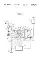
- FIG. 1illustrates a first embodiment of the present invention
- FIG. 2illustrates a second embodiment of the present invention.
- An artificial kidneyillustrated in FIG. 1, includes a haemodialyzer 1 having two compartments 2, 3 separated by a semi-permeable membrane 4 permitting the dialysis of the blood.
- the compartment 2is for the circulation of blood to be treated, while the compartment 3 is for the circulation of dialysis liquid.
- an intake 5 of the compartment 2is connected by a line 6 to a source 7 of a reference liquid, whose composition is completely determinate.
- a pump 8ensures the circulation of the reference liquid.
- the outlet 9 of the compartment 2is connected by a line 10 to the drain.
- the compartment 3 of the haemodialyzerhas an intake 11 connected via a feeding line 12 to a source 13 of dialysis liquid.
- the line 12comprises a flowmeter 15 and a pump 14 which ensures the circulation of the dialysis liquid.
- the source 13 of dialysis liquidis fed with water and with a concentrated solution present in a reservoir 16.
- the feeding rate of the source 13 with the concentrated solutionis regulated by a pump 17.
- the outlet 18 of the compartment 3is connected to a line 19 for discharging the used dialysis liquid to the drain.
- the feeding line 12 and the discharge line 19each have a bypass circuit, 20 and 21, respectively.
- These two bypass circuitsinclude a common portion 22 equipped with a sensor 23 constituted, for example, by an electrode specific to sodium.
- valves 24, 25, 26, 27, 28, 29makes it possible to selectively connect the common portion 22 equipped with the sensor 23 to the fresh dialysis liquid supply line 12 or to the line 19 for the evacuation of the used dialysis liquid.
- a control unit 30receives data coming from the flowmeter 15 and from the sensor 23. Unit 30 controls the positioning of the valves 24, 25, 26, 27, 28 and 29, as well as the operation of the pumps 8, 14, and 17.
- the operatorPrior to the operation of the artificial kidney, the operator supplies data to the unit 30 concerning the characteristics of the haemodialyzer used, as well as instructions relating to the delivery rate of the pump 8, the delivery rate of the pump 14, and to the desired conductivity of the dialysis liquid.
- the operation of the artificial kidneyis as follows.
- the reference liquid 7is put into circulation by means of the action of the pump 8. This liquid 7 passes into the haemodialyzer via the intake 5, to emerge therefrom via the outlet 9, before being discharged to the drain.
- the reference liquid usedmay be the sterile physiological serum solution used for rinsing and filling the circuit for the extracorporeal circulation of the blood to be treated.
- the unit 30controls the operation of the pump 17 in accordance with the conductivity set point established by the operator.
- the concentrateis diluted by means of the water feeding the source 13.
- the dialysis liquid thus preparedis caused to circulate by means of the pump 14.
- the operation of this pumpis controlled by the unit 30 in response to the flow rate values which are transmitted to it by the flowmeter 15.
- the dialysis liquidpasses into the compartment 3 of the haemodialyzer via the intake 11, then emerges therefrom via the outlet 18 before being passed to the drain by means of the line 19.
- exchangestake place between the two liquids by dialysis through the membrane 4, where the liquid with a high concentration of a certain substance becomes more diluted as the liquid with the lower concentration becomes stronger.
- the quantity of the substance transferred through the membraneis represented by the dialysance, which is a characteristic specific to each membrane.
- the formula for obtaining the dialysanceis as follows: ##EQU1## In this formula: Qd is the flow rate of the dialysis liquid measured by the flowmeter 15
- C indis the concentration of a substance at the intake of the compartment 3 of the haemodialyzer
- C outdis the concentration of the same substance at the outlet of the compartment 3 of the haemodialyzer
- C inbis the concentration of the same substance at the intake of the compartment 2 of the haemodialyzer.
- the liquid circulating in the compartment 2is a reference liquid whose composition is thoroughly known; therefore, the theoretical value of C inb is known.
- control unit 30varies the dialysis liquid concentration in accordance with a preestablished program, by varying the speed of the pump 17.
- the positioning of the valves 24, 25, 26, 27, 28 and 29is controlled by control unit 30 in such a way that the fresh dialysis liquid makes use of the bypass circuit 20, and hence washes the sensor 23 before passing into the haemodialyzer, while the used dialysis liquid circulates directly towards the drain without using the bypass circuit 21.
- the result of the measurement obtained by the sensor 23is transmitted to the unit 30 which records it as C ind1.
- the unit 30sends a signal to change positions of the valves 24, 25, 26, 27, 28 and 29, so that the fresh dialysis liquid follows the main line 12 to pass directly into the haemodialyzer, and so that the used dialysis liquid uses the bypass circuit 21 to wash the sensor 23.
- the result of this measurementis then transmitted to the unit 30 which records it as C outd1.
- the unit 30then changes the instruction for operating the pump 17, so as to change the composition of the dialysis liquid.
- the positioning of the valvesare reversed so that the common portion 22 is again in communication with the line 12.
- the measurement carried out by the sensor 23is transmitted to the unit 30 which records it as C ind2.
- the unit 30again reverses the positioning of the valves, so that the sensor 23 is able to measure the concentration of the used dialysis liquid. The result of the measurement is then transmitted and recorded as C outd2.
- the unit 30calculates a value for the concentration of the liquid circulating in the compartment 2 by means of the equation (3). This calculated value is compared with the theoretical value. When the two values coincide, the correct operation of the sensor 23 is confirmed. When this is not the case, provision may be made for setting off an alarm or the emission of a message warning the operator of the faulty operation of the sensor 23.
- the nature of the sensor 23may vary. It is possible to use a conductivity meter as well as any sensor capable of measuring the concentration of a substance present in the dialysis liquid. In the case where the measurements are effected by two different sensors, one for the fresh dialysis liquid and the other for the used dialysis liquid, the checking is effected for the set constituted by the two sensors, but does not allow the faulty sensor to be isolated in the case of incorrect operation.
- the dialysis liquid circuitis arranged so as to form a recirculation loop.
- a line 31 provided with a pump 34connects the intake line 12 for the fresh dialysis liquid to the line 19 for discharging the used dialysis liquid.
- the communication of the line 31 with the intake line 12 for the fresh dialysis liquidis obtained by means of a three-way valve 32.
- the communication of the line 31 with the discharge line 19 for the used dialysis liquidis obtained by means of a three-way valve 33.
- the conductivity meter 23is situated on the line 12 downstream from the valve 32.
- the control unit 30receives data from the conductivity meter 23 and controls the operation of the pump 34 as well as the positioning of the valves 32 and 33.
- the operation of the artificial kidney of the second embodimentis as follows.
- the reference liquid of known conductivity which is present in the reservoir 7is caused to circulate by means of the pump 8 controlled by the unit 30.
- the unit 30controls the positioning of the valves 32 and 33 so as to permit the circulation of the dialysis liquid directly from the source 13 to the intake 11 of the haemodialyzer, then from the outlet 18 to the drain.
- the pump 34does not operate.
- the starting of the pump 17is controlled by the unit 30 according to the conductivity set point fixed beforehand by the operator.
- the unit 30also controls the functioning of the pump 14 to provide a flow rate of the liquid of 0.5 l/min, which rate is controlled by the flowmeter 15.
- the unit 30controls the pump 14 to stop, the pump 34 to start, as well as a change in position of the valves 32 and 33 so as to cause the line 31 to communicate with the line 12 and with the line 19.
- the dialysis liquidthen recirculates in a loop at the flow rate fixed by the pump 34, which rate is at least 0.5 l/min.
- the measurements taken by the conductivity meter 23are transmitted to the unit 30. As long as the conductivity value varies, exchanges are taking place by diffusion through the membrane. When the conductivity measured by the conductivity meter 23 no longer changes, the dialysis liquid is in equilibrium with the reference liquid circulating on the other side of the membrane 4.
- the value then measuredis transmitted to the unit 30, which records it as the conductivity at equilibrium.
- the unit 30then stops the pump 34, restarts the pump 14, and reverses the position of the valves 32 and 33. This isolates the line 31 and allows the circulation of the dialysis liquid directly from the source 13 to the haemodialyzer 1, then from the haemodialyzer towards the drain without any recirculation.
- the unit 30then checks that the conductivity meter is functioning properly by comparing the recorded conductivity value of the dialysis liquid in equilibrium with the known conductivity value of the reference liquid.
- the present inventionis not limited to the examples described. Various modifications can be applied thereto without departing from its scope. Thus, it is possible to make provision for the sensor 23 to be recalibrated so as to make the two values coincide, if the calculated value of a characteristic of the reference liquid does not correspond to the theoretical value.
Landscapes
- Health & Medical Sciences (AREA)
- Heart & Thoracic Surgery (AREA)
- Urology & Nephrology (AREA)
- Anesthesiology (AREA)
- Vascular Medicine (AREA)
- Engineering & Computer Science (AREA)
- Emergency Medicine (AREA)
- Biomedical Technology (AREA)
- Hematology (AREA)
- Life Sciences & Earth Sciences (AREA)
- Animal Behavior & Ethology (AREA)
- General Health & Medical Sciences (AREA)
- Public Health (AREA)
- Veterinary Medicine (AREA)
- External Artificial Organs (AREA)
Abstract
Description
Claims (21)
Applications Claiming Priority (2)
| Application Number | Priority Date | Filing Date | Title |
|---|---|---|---|
| FR9208564 | 1992-07-06 | ||
| FR9208564AFR2693110B1 (en) | 1992-07-06 | 1992-07-06 | Method for verifying the operation of sensors located on a dialysis liquid circuit and device using it. |
Publications (1)
| Publication Number | Publication Date |
|---|---|
| US5399157Atrue US5399157A (en) | 1995-03-21 |
Family
ID=9431774
Family Applications (1)
| Application Number | Title | Priority Date | Filing Date |
|---|---|---|---|
| US08/085,932Expired - LifetimeUS5399157A (en) | 1992-07-06 | 1993-07-06 | Method for checking the operation of sensors situated in a dialysis liquid circuit |
Country Status (5)
| Country | Link |
|---|---|
| US (1) | US5399157A (en) |
| EP (1) | EP0578585B1 (en) |
| DE (1) | DE69305438T2 (en) |
| ES (1) | ES2095023T3 (en) |
| FR (1) | FR2693110B1 (en) |
Cited By (43)
| Publication number | Priority date | Publication date | Assignee | Title |
|---|---|---|---|---|
| US5567320A (en)* | 1993-12-17 | 1996-10-22 | Hospal Ag | Method for the determination of a significant parameter of the progess of an extracorporeal treatment of blood |
| US5629871A (en)* | 1995-06-07 | 1997-05-13 | Cobe Laboratories, Inc. | Wear trend analysis technique for components of a dialysis machine |
| US5631552A (en)* | 1992-09-30 | 1997-05-20 | Cobe Laboratories, Inc. | Hemodynamic monitor for detecting air bubbles |
| US5685988A (en)* | 1993-09-15 | 1997-11-11 | Malchesky; Paul | Dialysis process and system |
| US5725773A (en)* | 1994-11-12 | 1998-03-10 | Fresenius Ag | Method and apparatus for determining the quantity of oremic toxins removed by a hemodialysis treatment |
| EP1029554A3 (en)* | 1999-02-19 | 2001-06-06 | Fresenius Medical Care Deutschland GmbH | Apparatus for dialysis treatment |
| EP1327456A1 (en)* | 2002-01-10 | 2003-07-16 | Delphi Technologies, Inc. | Flow matching method and system using two transducers |
| US20040017201A1 (en)* | 1992-09-30 | 2004-01-29 | Brugger James M. | Differential fluid parameter determination |
| US20040129616A1 (en)* | 2002-11-14 | 2004-07-08 | Nikkiso Co. Ltd. | Blood purification device |
| US20050000868A1 (en)* | 2002-09-27 | 2005-01-06 | William Weigel | Volumetric fluid balance control for extracorporeal blood treatment |
| US6861266B1 (en)* | 1997-12-09 | 2005-03-01 | Gambro Lundia Ab | Method and device for calculating dialysis efficiency |
| US20070038191A1 (en)* | 2003-01-15 | 2007-02-15 | Burbank Jeffrey H | Waste balancing for extracorporeal blood treatment systems |
| US20070131595A1 (en)* | 2005-12-13 | 2007-06-14 | Gambro Lundia Ab | Method for conductivity calculation in a treatment fluid upstream and downstream a filtration unit in apparatuses for the blood treatment |
| WO2012016671A1 (en)* | 2010-07-31 | 2012-02-09 | Fresenius Medical Care Deutschland Gmbh | Device and method for detecting the direction of the flow of liquid through a dialyser |
| US8235931B2 (en) | 2003-01-15 | 2012-08-07 | Nxstage Medical, Inc. | Waste balancing for extracorporeal blood treatment systems |
| DE102011016869A1 (en)* | 2011-04-13 | 2012-10-18 | Fresenius Medical Care Deutschland Gmbh | Apparatus and method for conveying a liquid to a filter unit of a medical treatment device |
| EP2950835A4 (en)* | 2013-02-01 | 2016-11-02 | Medtronic Inc | RECIRCULATION DIALYSAT FLUID CIRCUIT FOR BLOOD MEASUREMENT |
| US9707328B2 (en) | 2013-01-09 | 2017-07-18 | Medtronic, Inc. | Sorbent cartridge to measure solute concentrations |
| US9713666B2 (en) | 2013-01-09 | 2017-07-25 | Medtronic, Inc. | Recirculating dialysate fluid circuit for blood measurement |
| US10022485B2 (en) | 2009-12-28 | 2018-07-17 | Fresenius Medical Care Deutschland Gmbh | Device and method for monitoring an extracorporeal blood treatment |
| US10195327B2 (en) | 2014-12-10 | 2019-02-05 | Medtronic, Inc. | Sensing and storage system for fluid balance |
| CN110225772A (en)* | 2016-11-25 | 2019-09-10 | 甘布罗伦迪亚股份公司 | Device for extracorporeal blood treatment |
| US10420872B2 (en) | 2014-12-10 | 2019-09-24 | Medtronic, Inc. | Degassing system for dialysis |
| US10478545B2 (en) | 2013-11-26 | 2019-11-19 | Medtronic, Inc. | Parallel modules for in-line recharging of sorbents using alternate duty cycles |
| US10532141B2 (en) | 2013-02-01 | 2020-01-14 | Medtronic, Inc. | Systems and methods for multifunctional volumetric fluid control |
| US10850016B2 (en) | 2013-02-01 | 2020-12-01 | Medtronic, Inc. | Modular fluid therapy system having jumpered flow paths and systems and methods for cleaning and disinfection |
| US10874787B2 (en) | 2014-12-10 | 2020-12-29 | Medtronic, Inc. | Degassing system for dialysis |
| US10926017B2 (en) | 2014-06-24 | 2021-02-23 | Medtronic, Inc. | Modular dialysate regeneration assembly |
| US10981148B2 (en) | 2016-11-29 | 2021-04-20 | Medtronic, Inc. | Zirconium oxide module conditioning |
| US11033667B2 (en) | 2018-02-02 | 2021-06-15 | Medtronic, Inc. | Sorbent manifold for a dialysis system |
| US11045790B2 (en) | 2014-06-24 | 2021-06-29 | Medtronic, Inc. | Stacked sorbent assembly |
| US11110215B2 (en) | 2018-02-23 | 2021-09-07 | Medtronic, Inc. | Degasser and vent manifolds for dialysis |
| US11154648B2 (en) | 2013-01-09 | 2021-10-26 | Medtronic, Inc. | Fluid circuits for sorbent cartridge with sensors |
| US11213616B2 (en) | 2018-08-24 | 2022-01-04 | Medtronic, Inc. | Recharge solution for zirconium phosphate |
| US11219880B2 (en) | 2013-11-26 | 2022-01-11 | Medtronic, Inc | System for precision recharging of sorbent materials using patient and session data |
| US11278654B2 (en) | 2017-12-07 | 2022-03-22 | Medtronic, Inc. | Pneumatic manifold for a dialysis system |
| US11565029B2 (en) | 2013-01-09 | 2023-01-31 | Medtronic, Inc. | Sorbent cartridge with electrodes |
| US11786645B2 (en) | 2013-02-01 | 2023-10-17 | Mozarc Medical Us Llc | Fluid circuit for delivery of renal replacement therapies |
| US11883794B2 (en) | 2017-06-15 | 2024-01-30 | Mozarc Medical Us Llc | Zirconium phosphate disinfection recharging and conditioning |
| US12128165B2 (en) | 2020-04-27 | 2024-10-29 | Mozarc Medical Us Llc | Dual stage degasser |
| EP4537863A1 (en) | 2023-10-13 | 2025-04-16 | Gambro Lundia AB | Extracorporeal blood treatment apparatus |
| US12285552B2 (en) | 2018-08-14 | 2025-04-29 | Mozarc Medical Us Llc | Precision dialysis therapy based on sorbent effluent analysis |
| US12397093B2 (en) | 2021-05-18 | 2025-08-26 | Mozarc Medical Us Llc | Sorbent cartridge designs |
Families Citing this family (8)
| Publication number | Priority date | Publication date | Assignee | Title |
|---|---|---|---|---|
| FR2712822B1 (en)* | 1993-11-26 | 1996-05-15 | Hospal Ind | Device and method for verifying the performance of an exchanger. |
| DE19655227B4 (en)* | 1995-02-13 | 2009-08-27 | Aksys, Ltd., Libertyville | Home dialysis machine components and methods of operation - where the machine includes water treatment, dialysate preparation and disinfection systems in user friendly, efficient and affordable haemodialysis package |
| DE19806900C1 (en)* | 1998-02-19 | 1999-04-22 | Fresenius Medical Care De Gmbh | Dialysis parameter provision method for blood dialysis device for treating kidney patients |
| DE19734992C1 (en)* | 1997-08-13 | 1998-10-01 | Fresenius Medical Care De Gmbh | Dialysis validation |
| EP1927370B1 (en) | 1997-08-13 | 2013-10-02 | Fresenius Medical Care Deutschland GmbH | Method for setting parameters for hemodialysis and blood processing device with a device for setting parameters for hemodialysis |
| DE10311547B4 (en) | 2003-03-17 | 2007-03-01 | ASM Anlagen und Systeme für Medizintechnik | Method for determining the effectiveness of a filter and filter arrangement for carrying out the method |
| EP3544651B1 (en) | 2016-11-25 | 2025-01-08 | Gambro Lundia AB | Apparatus for extracorporeal blood treatment |
| EP3544652B1 (en) | 2016-11-25 | 2023-04-05 | Gambro Lundia AB | Apparatus for extracorporeal blood treatment |
Citations (19)
| Publication number | Priority date | Publication date | Assignee | Title |
|---|---|---|---|---|
| US4153554A (en)* | 1977-02-22 | 1979-05-08 | American Micro-Bionics Corp. | Apparatus for use in artificial kidney system |
| US4209391A (en)* | 1978-11-06 | 1980-06-24 | Cordis Dow Corp. | Apparatus and method for automatically controlling hemodialysis at a pre-selected ultrafiltration rate |
| EP0097366A2 (en)* | 1982-06-21 | 1984-01-04 | Fresenius AG | Dialysis device with controlled composition of dialysis solution |
| US4508622A (en)* | 1982-06-21 | 1985-04-02 | Fresenius Ag | Dialysis apparatus with regulated mixing of the dialysis solution |
| DE3436748A1 (en)* | 1983-12-22 | 1985-07-04 | VEB Meßgerätewerk Zwönitz, DDR 9417 Zwönitz | Device for automatic determination of the efficacy of haemodialysis |
| US4683053A (en)* | 1984-05-08 | 1987-07-28 | Fresenius Ag | Hemodialysis device |
| US4736748A (en)* | 1986-04-05 | 1988-04-12 | Kuraray Co., Ltd. | Blood component monitoring system |
| US4897184A (en)* | 1986-10-31 | 1990-01-30 | Cobe Laboratories, Inc. | Fluid flow apparatus control and monitoring |
| US4923598A (en)* | 1987-06-23 | 1990-05-08 | Fresenius Ag | Apparatus for the treatment of blood in particular for hemodialysis and hemofiltration |
| US4966691A (en)* | 1987-07-20 | 1990-10-30 | Brous Donald W | Measurement and control of ultrafiltration in dialysis |
| US4967754A (en)* | 1988-06-15 | 1990-11-06 | Hospal Ag | Method and apparatus for anticipating side effects manifested in a patient during dialysis treatment |
| US5004548A (en)* | 1987-12-11 | 1991-04-02 | Hospal Industrie | Method and apparatus for rinsing and priming an exchanger |
| EP0428997A2 (en)* | 1989-11-17 | 1991-05-29 | E.I. Du Pont De Nemours And Company | Method for fabricating multilayer circuits |
| US5024756A (en)* | 1988-03-03 | 1991-06-18 | Gambro Ab | Dialysis system and method therefor |
| US5091094A (en)* | 1985-06-24 | 1992-02-25 | Veech Richard L | Hemodialysis processes & hemodialysis solutions |
| US5100554A (en)* | 1989-11-21 | 1992-03-31 | Fresenius Ag | Method for the in-vivo determination of hemodialysis parameters |
| US5171212A (en)* | 1991-02-08 | 1992-12-15 | Minnesota Mining And Manufacturing Company | Blood pumping system with backflow warning |
| US5195963A (en)* | 1990-02-09 | 1993-03-23 | Minnesota Mining And Manufacturing Company | Method and system for monitoring of blood constituents in vivo |
| US5211849A (en)* | 1991-10-11 | 1993-05-18 | Children's Hospital Medical Center | Hemofiltration system and method |
Family Cites Families (2)
| Publication number | Priority date | Publication date | Assignee | Title |
|---|---|---|---|---|
| FR2615289B1 (en)* | 1987-05-15 | 1989-07-21 | Hospal Ind | METHOD FOR DETERMINING THE NATREMIA OF A PATIENT AND ARTIFICIAL KIDNEY USING THE SAME |
| US5110477A (en)* | 1990-02-13 | 1992-05-05 | Howard David B | Dialyzer clearance check system |
- 1992
- 1992-07-06FRFR9208564Apatent/FR2693110B1/ennot_activeExpired - Fee Related
- 1993
- 1993-06-22DEDE69305438Tpatent/DE69305438T2/ennot_activeExpired - Fee Related
- 1993-06-22EPEP93420264Apatent/EP0578585B1/ennot_activeExpired - Lifetime
- 1993-06-22ESES93420264Tpatent/ES2095023T3/ennot_activeExpired - Lifetime
- 1993-07-06USUS08/085,932patent/US5399157A/ennot_activeExpired - Lifetime
Patent Citations (21)
| Publication number | Priority date | Publication date | Assignee | Title |
|---|---|---|---|---|
| US4153554A (en)* | 1977-02-22 | 1979-05-08 | American Micro-Bionics Corp. | Apparatus for use in artificial kidney system |
| US4209391A (en)* | 1978-11-06 | 1980-06-24 | Cordis Dow Corp. | Apparatus and method for automatically controlling hemodialysis at a pre-selected ultrafiltration rate |
| EP0097366A2 (en)* | 1982-06-21 | 1984-01-04 | Fresenius AG | Dialysis device with controlled composition of dialysis solution |
| US4508622A (en)* | 1982-06-21 | 1985-04-02 | Fresenius Ag | Dialysis apparatus with regulated mixing of the dialysis solution |
| DE3436748A1 (en)* | 1983-12-22 | 1985-07-04 | VEB Meßgerätewerk Zwönitz, DDR 9417 Zwönitz | Device for automatic determination of the efficacy of haemodialysis |
| US4683053A (en)* | 1984-05-08 | 1987-07-28 | Fresenius Ag | Hemodialysis device |
| US5091094A (en)* | 1985-06-24 | 1992-02-25 | Veech Richard L | Hemodialysis processes & hemodialysis solutions |
| US4736748A (en)* | 1986-04-05 | 1988-04-12 | Kuraray Co., Ltd. | Blood component monitoring system |
| US4897184A (en)* | 1986-10-31 | 1990-01-30 | Cobe Laboratories, Inc. | Fluid flow apparatus control and monitoring |
| US4923598A (en)* | 1987-06-23 | 1990-05-08 | Fresenius Ag | Apparatus for the treatment of blood in particular for hemodialysis and hemofiltration |
| US4966691A (en)* | 1987-07-20 | 1990-10-30 | Brous Donald W | Measurement and control of ultrafiltration in dialysis |
| US5004548A (en)* | 1987-12-11 | 1991-04-02 | Hospal Industrie | Method and apparatus for rinsing and priming an exchanger |
| EP0330892B1 (en)* | 1988-03-03 | 1994-07-06 | Gambro Ab | Dialysis system |
| US5024756A (en)* | 1988-03-03 | 1991-06-18 | Gambro Ab | Dialysis system and method therefor |
| US4967754A (en)* | 1988-06-15 | 1990-11-06 | Hospal Ag | Method and apparatus for anticipating side effects manifested in a patient during dialysis treatment |
| EP0428997A2 (en)* | 1989-11-17 | 1991-05-29 | E.I. Du Pont De Nemours And Company | Method for fabricating multilayer circuits |
| US5100554A (en)* | 1989-11-21 | 1992-03-31 | Fresenius Ag | Method for the in-vivo determination of hemodialysis parameters |
| US5195963A (en)* | 1990-02-09 | 1993-03-23 | Minnesota Mining And Manufacturing Company | Method and system for monitoring of blood constituents in vivo |
| US5171212A (en)* | 1991-02-08 | 1992-12-15 | Minnesota Mining And Manufacturing Company | Blood pumping system with backflow warning |
| US5211849A (en)* | 1991-10-11 | 1993-05-18 | Children's Hospital Medical Center | Hemofiltration system and method |
| US5211849B1 (en)* | 1991-10-11 | 1997-05-27 | Childrens Hosp Medical Center | Hemofiltration system and method |
Non-Patent Citations (2)
| Title |
|---|
| "Optimization of Sodium Dialysate Concentration by Plasma Water Conductivity Monitoring," T. Petitclerc et al., Progress in Artificial Organs-1985, ISAO Press, Cleveland 1986, pp. 234-236. |
| Optimization of Sodium Dialysate Concentration by Plasma Water Conductivity Monitoring, T. Petitclerc et al., Progress in Artificial Organs 1985, ISAO Press, Cleveland 1986, pp. 234 236.* |
Cited By (62)
| Publication number | Priority date | Publication date | Assignee | Title |
|---|---|---|---|---|
| US5631552A (en)* | 1992-09-30 | 1997-05-20 | Cobe Laboratories, Inc. | Hemodynamic monitor for detecting air bubbles |
| US20040017201A1 (en)* | 1992-09-30 | 2004-01-29 | Brugger James M. | Differential fluid parameter determination |
| US6912917B2 (en)* | 1992-09-30 | 2005-07-05 | Gambro, Inc. | Differential fluid parameter determination |
| US5685988A (en)* | 1993-09-15 | 1997-11-11 | Malchesky; Paul | Dialysis process and system |
| US5567320A (en)* | 1993-12-17 | 1996-10-22 | Hospal Ag | Method for the determination of a significant parameter of the progess of an extracorporeal treatment of blood |
| US5725773A (en)* | 1994-11-12 | 1998-03-10 | Fresenius Ag | Method and apparatus for determining the quantity of oremic toxins removed by a hemodialysis treatment |
| US5629871A (en)* | 1995-06-07 | 1997-05-13 | Cobe Laboratories, Inc. | Wear trend analysis technique for components of a dialysis machine |
| US6861266B1 (en)* | 1997-12-09 | 2005-03-01 | Gambro Lundia Ab | Method and device for calculating dialysis efficiency |
| EP1029554A3 (en)* | 1999-02-19 | 2001-06-06 | Fresenius Medical Care Deutschland GmbH | Apparatus for dialysis treatment |
| EP1327456A1 (en)* | 2002-01-10 | 2003-07-16 | Delphi Technologies, Inc. | Flow matching method and system using two transducers |
| US6752928B2 (en) | 2002-01-10 | 2004-06-22 | Delphi Technologies, Inc. | Flow matching method and system using two transducers |
| US20050000868A1 (en)* | 2002-09-27 | 2005-01-06 | William Weigel | Volumetric fluid balance control for extracorporeal blood treatment |
| US7112273B2 (en) | 2002-09-27 | 2006-09-26 | Nxstage Medical, Inc. | Volumetric fluid balance control for extracorporeal blood treatment |
| US7758532B2 (en)* | 2002-11-14 | 2010-07-20 | Nikkiso Co., Ltd. | Blood purification device |
| US20040129616A1 (en)* | 2002-11-14 | 2004-07-08 | Nikkiso Co. Ltd. | Blood purification device |
| US20070038191A1 (en)* | 2003-01-15 | 2007-02-15 | Burbank Jeffrey H | Waste balancing for extracorporeal blood treatment systems |
| US7686778B2 (en) | 2003-01-15 | 2010-03-30 | Nxstage Medical, Inc. | Waste balancing for extracorporeal blood treatment systems |
| US8235931B2 (en) | 2003-01-15 | 2012-08-07 | Nxstage Medical, Inc. | Waste balancing for extracorporeal blood treatment systems |
| US20070131595A1 (en)* | 2005-12-13 | 2007-06-14 | Gambro Lundia Ab | Method for conductivity calculation in a treatment fluid upstream and downstream a filtration unit in apparatuses for the blood treatment |
| US7815809B2 (en)* | 2005-12-13 | 2010-10-19 | Gambro Lundia Ab | Method for conductivity calculation in a treatment fluid upstream and downstream a filtration unit in apparatuses for the blood treatment |
| US10022485B2 (en) | 2009-12-28 | 2018-07-17 | Fresenius Medical Care Deutschland Gmbh | Device and method for monitoring an extracorporeal blood treatment |
| US10973973B2 (en) | 2009-12-28 | 2021-04-13 | Fresenius Medical Gare Deutschland GmbH | Device and method for monitoring an extracorporeal blood treatment |
| CN103052414A (en)* | 2010-07-31 | 2013-04-17 | 弗雷泽纽斯医疗保健德国有限公司 | Device and method for detecting direction of flow of liquid through dialyser |
| US9132224B2 (en) | 2010-07-31 | 2015-09-15 | Fresenius Medical Care Deutschland Gmbh | Device and method for detecting the direction of the flow of liquid through a dialyzer |
| WO2012016671A1 (en)* | 2010-07-31 | 2012-02-09 | Fresenius Medical Care Deutschland Gmbh | Device and method for detecting the direction of the flow of liquid through a dialyser |
| CN103052414B (en)* | 2010-07-31 | 2015-08-19 | 弗雷泽纽斯医疗保健德国有限公司 | For detecting the apparatus and method of the fluid flow direction by dialyser |
| DE102011016869A1 (en)* | 2011-04-13 | 2012-10-18 | Fresenius Medical Care Deutschland Gmbh | Apparatus and method for conveying a liquid to a filter unit of a medical treatment device |
| US9662430B2 (en) | 2011-04-13 | 2017-05-30 | Fresenius Medical Care Deutschland Gmbh | Device and method for conveying a fluid to a filter unit of a medical treatment apparatus |
| US10881777B2 (en) | 2013-01-09 | 2021-01-05 | Medtronic, Inc. | Recirculating dialysate fluid circuit for blood measurement |
| US9713666B2 (en) | 2013-01-09 | 2017-07-25 | Medtronic, Inc. | Recirculating dialysate fluid circuit for blood measurement |
| US12161788B2 (en) | 2013-01-09 | 2024-12-10 | Mozarc Medical Us Llc | Fluid circuits for sorbent cartridges with sensors |
| US11857712B2 (en) | 2013-01-09 | 2024-01-02 | Mozarc Medical Us Llc | Recirculating dialysate fluid circuit for measurement of blood solute species |
| US11154648B2 (en) | 2013-01-09 | 2021-10-26 | Medtronic, Inc. | Fluid circuits for sorbent cartridge with sensors |
| US10583236B2 (en) | 2013-01-09 | 2020-03-10 | Medtronic, Inc. | Recirculating dialysate fluid circuit for blood measurement |
| US9707328B2 (en) | 2013-01-09 | 2017-07-18 | Medtronic, Inc. | Sorbent cartridge to measure solute concentrations |
| US11565029B2 (en) | 2013-01-09 | 2023-01-31 | Medtronic, Inc. | Sorbent cartridge with electrodes |
| EP2950835A4 (en)* | 2013-02-01 | 2016-11-02 | Medtronic Inc | RECIRCULATION DIALYSAT FLUID CIRCUIT FOR BLOOD MEASUREMENT |
| US10532141B2 (en) | 2013-02-01 | 2020-01-14 | Medtronic, Inc. | Systems and methods for multifunctional volumetric fluid control |
| US10850016B2 (en) | 2013-02-01 | 2020-12-01 | Medtronic, Inc. | Modular fluid therapy system having jumpered flow paths and systems and methods for cleaning and disinfection |
| US11786645B2 (en) | 2013-02-01 | 2023-10-17 | Mozarc Medical Us Llc | Fluid circuit for delivery of renal replacement therapies |
| US10478545B2 (en) | 2013-11-26 | 2019-11-19 | Medtronic, Inc. | Parallel modules for in-line recharging of sorbents using alternate duty cycles |
| US11219880B2 (en) | 2013-11-26 | 2022-01-11 | Medtronic, Inc | System for precision recharging of sorbent materials using patient and session data |
| US11673118B2 (en) | 2014-06-24 | 2023-06-13 | Mozarc Medical Us Llc | Stacked sorbent assembly |
| US10926017B2 (en) | 2014-06-24 | 2021-02-23 | Medtronic, Inc. | Modular dialysate regeneration assembly |
| US11045790B2 (en) | 2014-06-24 | 2021-06-29 | Medtronic, Inc. | Stacked sorbent assembly |
| US10195327B2 (en) | 2014-12-10 | 2019-02-05 | Medtronic, Inc. | Sensing and storage system for fluid balance |
| US10420872B2 (en) | 2014-12-10 | 2019-09-24 | Medtronic, Inc. | Degassing system for dialysis |
| US10874787B2 (en) | 2014-12-10 | 2020-12-29 | Medtronic, Inc. | Degassing system for dialysis |
| CN110225772A (en)* | 2016-11-25 | 2019-09-10 | 甘布罗伦迪亚股份公司 | Device for extracorporeal blood treatment |
| CN110225772B (en)* | 2016-11-25 | 2021-10-22 | 甘布罗伦迪亚股份公司 | Device for extracorporeal blood treatment |
| US11642654B2 (en) | 2016-11-29 | 2023-05-09 | Medtronic, Inc | Zirconium oxide module conditioning |
| US10981148B2 (en) | 2016-11-29 | 2021-04-20 | Medtronic, Inc. | Zirconium oxide module conditioning |
| US11883794B2 (en) | 2017-06-15 | 2024-01-30 | Mozarc Medical Us Llc | Zirconium phosphate disinfection recharging and conditioning |
| US11278654B2 (en) | 2017-12-07 | 2022-03-22 | Medtronic, Inc. | Pneumatic manifold for a dialysis system |
| US11033667B2 (en) | 2018-02-02 | 2021-06-15 | Medtronic, Inc. | Sorbent manifold for a dialysis system |
| US11110215B2 (en) | 2018-02-23 | 2021-09-07 | Medtronic, Inc. | Degasser and vent manifolds for dialysis |
| US12285552B2 (en) | 2018-08-14 | 2025-04-29 | Mozarc Medical Us Llc | Precision dialysis therapy based on sorbent effluent analysis |
| US11213616B2 (en) | 2018-08-24 | 2022-01-04 | Medtronic, Inc. | Recharge solution for zirconium phosphate |
| US12128165B2 (en) | 2020-04-27 | 2024-10-29 | Mozarc Medical Us Llc | Dual stage degasser |
| US12397093B2 (en) | 2021-05-18 | 2025-08-26 | Mozarc Medical Us Llc | Sorbent cartridge designs |
| EP4537863A1 (en) | 2023-10-13 | 2025-04-16 | Gambro Lundia AB | Extracorporeal blood treatment apparatus |
| WO2025078646A1 (en) | 2023-10-13 | 2025-04-17 | Gambro Lundia Ab | Extracorporeal blood treatment apparatus |
Also Published As
| Publication number | Publication date |
|---|---|
| DE69305438T2 (en) | 1997-04-30 |
| DE69305438D1 (en) | 1996-11-21 |
| FR2693110B1 (en) | 1994-08-19 |
| FR2693110A1 (en) | 1994-01-07 |
| ES2095023T3 (en) | 1997-02-01 |
| EP0578585B1 (en) | 1996-10-16 |
| EP0578585A1 (en) | 1994-01-12 |
Similar Documents
| Publication | Publication Date | Title |
|---|---|---|
| US5399157A (en) | Method for checking the operation of sensors situated in a dialysis liquid circuit | |
| KR100636045B1 (en) | Method and apparatus for performing controlled ultrafiltration during hemodialysis | |
| JP2532261B2 (en) | Equipment for hemodialysis treatment | |
| US7507219B2 (en) | Method for determining the intraperitoneal volume and device for peritoneal dialysis | |
| US6126831A (en) | Method and device for determining hemodialysis parameters | |
| JP4132342B2 (en) | Method and apparatus for determining hemodialysis parameters | |
| JP5221613B2 (en) | Control device and control method for blood treatment facility | |
| US7674236B2 (en) | Device and method for detecting complications during an extracorporeal blood treatment | |
| CN101918053B (en) | Device for determining recirculation or cardiopulmonary recirculation in a fistula and blood treatment apparatus incorporating the same | |
| JP2009183732A (en) | Blood treatment system | |
| KR20040071250A (en) | Equipment for controlling blood flow in an extracorporeal blood circuit | |
| EP3302608B1 (en) | Apparatus for extracorporeal blood treatment iii | |
| JPH11137668A (en) | Dialysis apparatus for adjusting sodium concentration | |
| JP7161477B2 (en) | Dialysate Concentration Sensor Diagnostics | |
| US4857181A (en) | Control of cleaning of dialysate preparation apparatus | |
| JP2001218837A (en) | Method for determing parameter indicating progress of extracorporeal blood treatment | |
| CA1183461A (en) | Dialysate preparation apparatus | |
| US20220126009A1 (en) | Flowmeter for proportioning water in dialysis system | |
| JPS61131753A (en) | Disinfection apparatus for artificial dialytic apparatus | |
| EP3673929A1 (en) | Apparatus for extracorporeal blood treatment | |
| JPS649025B2 (en) |
Legal Events
| Date | Code | Title | Description |
|---|---|---|---|
| STPP | Information on status: patent application and granting procedure in general | Free format text:APPLICATION UNDERGOING PREEXAM PROCESSING | |
| AS | Assignment | Owner name:HOSPAL INDUSTRIE Free format text:ASSIGNMENT OF ASSIGNORS INTEREST;ASSIGNORS:GOUX, NICOLAS;BENE, BERNARD;REEL/FRAME:006658/0269;SIGNING DATES FROM | |
| FEPP | Fee payment procedure | Free format text:PAYOR NUMBER ASSIGNED (ORIGINAL EVENT CODE: ASPN); ENTITY STATUS OF PATENT OWNER: LARGE ENTITY | |
| FPAY | Fee payment | Year of fee payment:4 | |
| FPAY | Fee payment | Year of fee payment:8 | |
| REMI | Maintenance fee reminder mailed | ||
| AS | Assignment | Owner name:GAMBRO INDUSTRIES, FRANCE Free format text:MERGER;ASSIGNOR:HOSPAL INDUSTRIE SAS;REEL/FRAME:017624/0704 Effective date:20050705 | |
| FPAY | Fee payment | Year of fee payment:12 | |
| AS | Assignment | Owner name:CITICORP TRUSTEE COMPANY LIMITED, AS SECURITY AGEN Free format text:SECURITY AGREEMENT;ASSIGNOR:GAMBRO INDUSTRIES SAS;REEL/FRAME:018552/0623 Effective date:20061117 | |
| FEPP | Fee payment procedure | Free format text:PAYER NUMBER DE-ASSIGNED (ORIGINAL EVENT CODE: RMPN); ENTITY STATUS OF PATENT OWNER: LARGE ENTITY Free format text:PAYOR NUMBER ASSIGNED (ORIGINAL EVENT CODE: ASPN); ENTITY STATUS OF PATENT OWNER: LARGE ENTITY | |
| AS | Assignment | Owner name:GAMBRO INDUSTRIES SAS, COLORADO Free format text:RELEASE OF SECURITY INTEREST IN PATENTS;ASSIGNOR:CITICORP TRUSTEE COMPANY LIMITED, AS SECURITY AGENT;REEL/FRAME:027455/0333 Effective date:20111207 |