US5399154A - Constant torque range-of-motion splint - Google Patents
Constant torque range-of-motion splintDownload PDFInfo
- Publication number
- US5399154A US5399154AUS08/085,758US8575893AUS5399154AUS 5399154 AUS5399154 AUS 5399154AUS 8575893 AUS8575893 AUS 8575893AUS 5399154 AUS5399154 AUS 5399154A
- Authority
- US
- United States
- Prior art keywords
- range
- splint
- motion
- arm
- drive pulley
- Prior art date
- Legal status (The legal status is an assumption and is not a legal conclusion. Google has not performed a legal analysis and makes no representation as to the accuracy of the status listed.)
- Expired - Lifetime
Links
- 230000007246mechanismEffects0.000claimsabstractdescription67
- 230000033001locomotionEffects0.000claimsabstractdescription32
- 238000010319rehabilitative therapyMethods0.000claimsabstractdescription7
- 230000008878couplingEffects0.000claims3
- 238000010168coupling processMethods0.000claims3
- 238000005859coupling reactionMethods0.000claims3
- 210000000689upper legAnatomy0.000description12
- 208000006111contractureDiseases0.000description6
- 210000002414legAnatomy0.000description6
- 210000003127kneeAnatomy0.000description4
- 206010062575Muscle contractureDiseases0.000description3
- 208000027418Wounds and injuryDiseases0.000description2
- 230000006378damageEffects0.000description2
- 208000014674injuryDiseases0.000description2
- 238000002560therapeutic procedureMethods0.000description2
- 244000309466calfSpecies0.000description1
- 230000003247decreasing effectEffects0.000description1
- 210000001513elbowAnatomy0.000description1
- 210000003414extremityAnatomy0.000description1
- 238000000034methodMethods0.000description1
- 238000001356surgical procedureMethods0.000description1
- 210000000707wristAnatomy0.000description1
Images


Classifications
- A—HUMAN NECESSITIES
- A61—MEDICAL OR VETERINARY SCIENCE; HYGIENE
- A61F—FILTERS IMPLANTABLE INTO BLOOD VESSELS; PROSTHESES; DEVICES PROVIDING PATENCY TO, OR PREVENTING COLLAPSING OF, TUBULAR STRUCTURES OF THE BODY, e.g. STENTS; ORTHOPAEDIC, NURSING OR CONTRACEPTIVE DEVICES; FOMENTATION; TREATMENT OR PROTECTION OF EYES OR EARS; BANDAGES, DRESSINGS OR ABSORBENT PADS; FIRST-AID KITS
- A61F5/00—Orthopaedic methods or devices for non-surgical treatment of bones or joints; Nursing devices ; Anti-rape devices
- A61F5/01—Orthopaedic devices, e.g. long-term immobilising or pressure directing devices for treating broken or deformed bones such as splints, casts or braces
- A61F5/0102—Orthopaedic devices, e.g. long-term immobilising or pressure directing devices for treating broken or deformed bones such as splints, casts or braces specially adapted for correcting deformities of the limbs or for supporting them; Ortheses, e.g. with articulations
- A61F5/0127—Orthopaedic devices, e.g. long-term immobilising or pressure directing devices for treating broken or deformed bones such as splints, casts or braces specially adapted for correcting deformities of the limbs or for supporting them; Ortheses, e.g. with articulations for the feet
- A—HUMAN NECESSITIES
- A61—MEDICAL OR VETERINARY SCIENCE; HYGIENE
- A61F—FILTERS IMPLANTABLE INTO BLOOD VESSELS; PROSTHESES; DEVICES PROVIDING PATENCY TO, OR PREVENTING COLLAPSING OF, TUBULAR STRUCTURES OF THE BODY, e.g. STENTS; ORTHOPAEDIC, NURSING OR CONTRACEPTIVE DEVICES; FOMENTATION; TREATMENT OR PROTECTION OF EYES OR EARS; BANDAGES, DRESSINGS OR ABSORBENT PADS; FIRST-AID KITS
- A61F5/00—Orthopaedic methods or devices for non-surgical treatment of bones or joints; Nursing devices ; Anti-rape devices
- A61F5/01—Orthopaedic devices, e.g. long-term immobilising or pressure directing devices for treating broken or deformed bones such as splints, casts or braces
- A61F5/0102—Orthopaedic devices, e.g. long-term immobilising or pressure directing devices for treating broken or deformed bones such as splints, casts or braces specially adapted for correcting deformities of the limbs or for supporting them; Ortheses, e.g. with articulations
- A61F5/0123—Orthopaedic devices, e.g. long-term immobilising or pressure directing devices for treating broken or deformed bones such as splints, casts or braces specially adapted for correcting deformities of the limbs or for supporting them; Ortheses, e.g. with articulations for the knees
- A61F5/0125—Orthopaedic devices, e.g. long-term immobilising or pressure directing devices for treating broken or deformed bones such as splints, casts or braces specially adapted for correcting deformities of the limbs or for supporting them; Ortheses, e.g. with articulations for the knees the device articulating around a single pivot-point
- A—HUMAN NECESSITIES
- A61—MEDICAL OR VETERINARY SCIENCE; HYGIENE
- A61F—FILTERS IMPLANTABLE INTO BLOOD VESSELS; PROSTHESES; DEVICES PROVIDING PATENCY TO, OR PREVENTING COLLAPSING OF, TUBULAR STRUCTURES OF THE BODY, e.g. STENTS; ORTHOPAEDIC, NURSING OR CONTRACEPTIVE DEVICES; FOMENTATION; TREATMENT OR PROTECTION OF EYES OR EARS; BANDAGES, DRESSINGS OR ABSORBENT PADS; FIRST-AID KITS
- A61F5/00—Orthopaedic methods or devices for non-surgical treatment of bones or joints; Nursing devices ; Anti-rape devices
- A61F5/01—Orthopaedic devices, e.g. long-term immobilising or pressure directing devices for treating broken or deformed bones such as splints, casts or braces
- A61F5/0102—Orthopaedic devices, e.g. long-term immobilising or pressure directing devices for treating broken or deformed bones such as splints, casts or braces specially adapted for correcting deformities of the limbs or for supporting them; Ortheses, e.g. with articulations
- A61F5/013—Orthopaedic devices, e.g. long-term immobilising or pressure directing devices for treating broken or deformed bones such as splints, casts or braces specially adapted for correcting deformities of the limbs or for supporting them; Ortheses, e.g. with articulations for the arms, hands or fingers
- A—HUMAN NECESSITIES
- A61—MEDICAL OR VETERINARY SCIENCE; HYGIENE
- A61F—FILTERS IMPLANTABLE INTO BLOOD VESSELS; PROSTHESES; DEVICES PROVIDING PATENCY TO, OR PREVENTING COLLAPSING OF, TUBULAR STRUCTURES OF THE BODY, e.g. STENTS; ORTHOPAEDIC, NURSING OR CONTRACEPTIVE DEVICES; FOMENTATION; TREATMENT OR PROTECTION OF EYES OR EARS; BANDAGES, DRESSINGS OR ABSORBENT PADS; FIRST-AID KITS
- A61F5/00—Orthopaedic methods or devices for non-surgical treatment of bones or joints; Nursing devices ; Anti-rape devices
- A61F5/01—Orthopaedic devices, e.g. long-term immobilising or pressure directing devices for treating broken or deformed bones such as splints, casts or braces
- A61F5/0102—Orthopaedic devices, e.g. long-term immobilising or pressure directing devices for treating broken or deformed bones such as splints, casts or braces specially adapted for correcting deformities of the limbs or for supporting them; Ortheses, e.g. with articulations
- A61F2005/0132—Additional features of the articulation
- A61F2005/0137—Additional features of the articulation with two parallel pivots
- A61F2005/0139—Additional features of the articulation with two parallel pivots geared
- A—HUMAN NECESSITIES
- A61—MEDICAL OR VETERINARY SCIENCE; HYGIENE
- A61F—FILTERS IMPLANTABLE INTO BLOOD VESSELS; PROSTHESES; DEVICES PROVIDING PATENCY TO, OR PREVENTING COLLAPSING OF, TUBULAR STRUCTURES OF THE BODY, e.g. STENTS; ORTHOPAEDIC, NURSING OR CONTRACEPTIVE DEVICES; FOMENTATION; TREATMENT OR PROTECTION OF EYES OR EARS; BANDAGES, DRESSINGS OR ABSORBENT PADS; FIRST-AID KITS
- A61F5/00—Orthopaedic methods or devices for non-surgical treatment of bones or joints; Nursing devices ; Anti-rape devices
- A61F5/01—Orthopaedic devices, e.g. long-term immobilising or pressure directing devices for treating broken or deformed bones such as splints, casts or braces
- A61F5/0102—Orthopaedic devices, e.g. long-term immobilising or pressure directing devices for treating broken or deformed bones such as splints, casts or braces specially adapted for correcting deformities of the limbs or for supporting them; Ortheses, e.g. with articulations
- A61F2005/0132—Additional features of the articulation
- A61F2005/0158—Additional features of the articulation with locking means
- A61F2005/016—Additional features of the articulation with locking means in standing position
- A—HUMAN NECESSITIES
- A61—MEDICAL OR VETERINARY SCIENCE; HYGIENE
- A61F—FILTERS IMPLANTABLE INTO BLOOD VESSELS; PROSTHESES; DEVICES PROVIDING PATENCY TO, OR PREVENTING COLLAPSING OF, TUBULAR STRUCTURES OF THE BODY, e.g. STENTS; ORTHOPAEDIC, NURSING OR CONTRACEPTIVE DEVICES; FOMENTATION; TREATMENT OR PROTECTION OF EYES OR EARS; BANDAGES, DRESSINGS OR ABSORBENT PADS; FIRST-AID KITS
- A61F5/00—Orthopaedic methods or devices for non-surgical treatment of bones or joints; Nursing devices ; Anti-rape devices
- A61F5/01—Orthopaedic devices, e.g. long-term immobilising or pressure directing devices for treating broken or deformed bones such as splints, casts or braces
- A61F5/0102—Orthopaedic devices, e.g. long-term immobilising or pressure directing devices for treating broken or deformed bones such as splints, casts or braces specially adapted for correcting deformities of the limbs or for supporting them; Ortheses, e.g. with articulations
- A61F2005/0132—Additional features of the articulation
- A61F2005/0165—Additional features of the articulation with limits of movement
- A61F2005/0167—Additional features of the articulation with limits of movement adjustable
- A—HUMAN NECESSITIES
- A61—MEDICAL OR VETERINARY SCIENCE; HYGIENE
- A61F—FILTERS IMPLANTABLE INTO BLOOD VESSELS; PROSTHESES; DEVICES PROVIDING PATENCY TO, OR PREVENTING COLLAPSING OF, TUBULAR STRUCTURES OF THE BODY, e.g. STENTS; ORTHOPAEDIC, NURSING OR CONTRACEPTIVE DEVICES; FOMENTATION; TREATMENT OR PROTECTION OF EYES OR EARS; BANDAGES, DRESSINGS OR ABSORBENT PADS; FIRST-AID KITS
- A61F5/00—Orthopaedic methods or devices for non-surgical treatment of bones or joints; Nursing devices ; Anti-rape devices
- A61F5/01—Orthopaedic devices, e.g. long-term immobilising or pressure directing devices for treating broken or deformed bones such as splints, casts or braces
- A61F5/0102—Orthopaedic devices, e.g. long-term immobilising or pressure directing devices for treating broken or deformed bones such as splints, casts or braces specially adapted for correcting deformities of the limbs or for supporting them; Ortheses, e.g. with articulations
- A61F2005/0132—Additional features of the articulation
- A61F2005/0179—Additional features of the articulation with spring means
Definitions
- the present inventionrelates to dynamic splints or braces for applying torque across joints undergoing rehabilitative therapy.
- Range-of-motion or ROM splintsare dynamic devices commonly used during physical rehabilitative therapy to increase the range of motion over which the patient can flex or extend the joint. Splints of this type are generally known, and disclosed, for example, in the Mitchell et al. U.S. Pat. No. 5,036,837.
- range-of-motion splintstypically include spring loaded brace sections for applying torque to the injured joint in opposition to the contracture. This force tends to gradually increase the working range or angle of joint motion. Springs, however, are passive devices and exert decreasing amounts of force as they retract. The amount of decrease in torque per change in the angle of the brace sections is known as the apparent elasticity of the splint. Most range-of-motion splints, therefore, require continual adjustment to maintain a constant amount of applied torque as the patient's range of joint motion increases during therapy. These torque adjusting procedures are time consuming and inconvenient.
- the present inventionis a range-of-motion splint capable of applying relatively constant torque over the entire working range of a joint undergoing rehabilitative therapy.
- the splintincludes first and second brace sections configured to engage portions of a patient's body on first and second sides of the joint, respectively, and a drive assembly.
- the first and second brace sectionsinclude first and second arms, respectively, pivotally connected about a splint pivot axis by a pivot mechanism.
- the drive assemblyincludes a driven pulley, a drive pulley, a biasing member and a linkage.
- the driven pulleyis mounted to the second arm about the splint pivot axis.
- the drive pulleyis mounted to the first arm about a drive axis spaced from the splint pivot axis.
- the biasing memberis connected to the first arm and the drive pulley and applies torque to the drive pulley.
- the linkagecouples the drive pulley to the driven pulley to apply torque between the first and second brace sections.
- the biasing memberincludes a spiral spring.
- the springis positioned about the drive axis and has a first end mounted to the first arm and a second end mounted to the drive pulley.
- the drive pulley and driven pulleyare coupled by a belt.
- the torque adjusting mechanismincludes a worm wheel and an adjustment worm.
- the worm wheelis rotatably mounted to the first arm about the drive axis and is connected to the first end of the spiral spring.
- the adjustment wormis rotatably mounted to the first arm and engaged with the worm wheel. The adjustment worm is rotated to rotate the worm wheel and adjust the tension on the spiral spring.
- the splintincludes a locking mechanism for locking the angular position of the first and second brace sections with respect to one another.
- the locking mechanismincludes a key actuated slide which engages and prevents rotation of the drive pulley.
- the splintincludes an adjustable stop mechanism for limiting the range of motion between the first and second brace sections.
- the stop mechanismincludes one or more washers with inwardly extending tabs rigidly mounted with respect to the first arm, and a bushing including a tab-engaging lug mounted for rotation with the driven pulley and extending into the washers. The range of rotational motion of the driven pulley is limited by engagement of the bushing lug with the washer tabs.
- FIG. 1is a perspective view of a range-of-motion splint in accordance with the present invention.
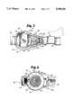
- FIG. 2is a sectional view of the drive assembly shown in FIG. 1, taken along a longitudinal plane extending through the center of the drive and driven mechanisms.
- FIG. 3is a side view of the drive assembly shown in FIG. 1, with portions thereof cut away to illustrate the drive pulley, driven pulley and locking mechanism.
- FIG. 4is a side view of the drive assembly shown in FIG. 1, with portions thereof cut away to illustrate the coil spring and torque adjusting mechanism.
- FIG. 5is an exploded perspective view of the adjustable range of motion stop mechanism of the splint shown in FIG. 1.
- FIG. 6is a sectional view of the thigh-engaging brace section of the splint shown in FIG. 1, taken along a longitudinal plane extending through the screws and bolt.
- a constant torques dynamic range-of-motion splint 10 in accordance with the present inventionis illustrated generally in FIG. 1.
- the illustrated embodiment of splint 10is configured for rehabilitative knee therapy and includes a thigh-engaging brace section 12 (i.e., a first brace section for engaging a portion of the patient's body on a first side of a joint), a calf-engaging brace section 14 (i.e. a second brace section for engaging a portion of the patient's body on a second side of a joint), and constant torque drive assembly 16.
- Brace sections 12 and 14include first and second arms 18 and 20, respectively, which are connected about a first or splint pivot axis by pivot mechanism 24.
- Drive assembly 16can be described with reference to FIGS. 2-4. As shown, drive assembly 16 includes a drive mechanism 26 and a driven mechanism 28 mechanically interconnected by a linkage such as belt 30. Arm 18 includes baseplate 32. Driven mechanism 26, driven mechanism 28 and belt 30 are positioned within a housing formed by baseplates 32 and 34. Driven mechanism 28 includes flange 36, bushing 38 and driven pulley 42, all of which are fastened together by threaded shaft 40 which defines the splint pivot axis. Flange 36 is fastened to arm 20 of calf-engaging brace section 14 by rivets 44, and journaled into an aperture through baseplate 34 for rotation about the splint pivot axis.
- a cap 48 including threaded shaft 40is secured to the side of flange 36 opposite baseplate 34.
- Bushing 38is journaled into an aperture through baseplate 32 by bushing 46, also for rotation about the splint pivot axis. Torque applied to driven pulley 42 by drive mechanism 26 therefore rotates calf-engaging brace section 14 with respect to thigh-engaging brace section 12.
- Drive mechanism 26is mounted to arm 18 of thigh-engaging brace section 12 at a location spaced from driven mechanism 28 and the splint pivot axis, and includes a biasing member such as spring 50 for generating a bias torque.
- the bias torque generated by spring 50is coupled to driven mechanism 28 by belt 30.
- drive mechanism 26includes worm wheel 52, adjustment worm 54 and drive pulley 56.
- Drive pulley 56is mounted for rotation about a drive axis by a bearing 58 which includes a shaft 67 mounted for rotation about bearing sections 61 and 63. Bearing sections 61 and 63 secured to baseplates 32 and 34 by screws 60 and 65, respectively.
- Drive pulley 56is press-fit onto shaft 67.
- Worm wheel 52is a ring-shaped member concentrically positioned with respect to drive pulley 56 in a recess in baseplate 32.
- Spring 50is a spiral-type spring in the embodiment shown, and is wound around drive pulley 56 within worm wheel 52.
- a first end 62 of spring 50is engaged with worm wheel 52.
- the second end 64 of spring 50is engaged with drive pulley 56 by means of shaft 67.
- Adjustment worm 54is positioned within recesses in baseplates 32 and 34 for engagement with the worm wheel 52 and rotation about an axis perpendicular to the drive axis. Adjustment worm 54 and worm wheel 52 function as a torque adjusting mechanism. As shown in FIG.
- adjustment worm 54ends of adjustment worm 54 extend into recesses in the outside of baseplates 32 and 34.
- a key or other wrench(not shown) can be used to rotate adjustment worm 54, thereby rotating worm wheel 52 to wind and unwind spring 50 in order to increase or decrease the amount of torque applied to drive pulley 56 by the spring.
- driven pulley 42 and drive pulley 56can be eccentric (i.e., have varying radii) to compensate for slight variations in the torque generated by spring 50 as it is wound and unwound, or to otherwise vary the relationship between the splint angle and applied torque.
- gears(not shown) can be substituted for pulleys 42 and 56, with the teeth of the gears functioning as the linkage.
- locking mechanism 66prevents relative movement between brace sections 12 and 14.
- locking mechanism 66includes key 68, slide 70 and pin 72.
- Slide 70is positioned in a recess in baseplate 34 that guides the slide for motion along a linear path toward and away from drive pulley 56.
- Slide 70includes a teeth-engaging tip 74 on the end adjacent drive pulley 56.
- Pin 72is mounted to and extends from slide 70.
- Key 68is positioned in a recess in baseplate 34 that guides the key for motion along a linear path generally perpendicular to that of slide 70, and includes an elongated slot 76 which extends at a non-parallel angle with respect to the key path of motion. Opposite ends of key 68 extend beyond the baseplate 34.
- Pin 72extends into slot 76 and couples the motion of key 68 to slide 70.
- the patient or cliniciancan force the key back and forth along its path of motion, and engage and disengage slide tip 74 with the teeth of drive pulley 56.
- Brace sections 12 and 14can therefore be conveniently and rigidly locked with respect to one another at any position within the range of motion over which splint 10 is configured for operation.
- An adjustable range-of-motion stop mechanism 80enables a clinician to control the range of rotational motion between brace sections 12 and 14.
- stop mechanism 80includes pins 82, stop washers 84 and a lug 86 which extends from bushing 38 of driven mechanism 28.
- Three pins 82are circumferentially positioned around the splint pivot axis and extend from baseplate 32.
- Washers 84each include a plurality of circumferentially spaced apertures 87 and a tab 88 that extends into the central aperture of the washer. Washer apertures 87 are spaced so they can be received by pins 82 with tabs 88 at any desired circumferential position.
- Washers 84are placed on top of one another on pins 82 with tabs 88 positioned to engage bushing lug 86 at the desired stop points.
- Cap 90covers washers 84 and is screwed into bushing 38 to secure the washers in place. Since bushing 38 rotates with driven mechanism 28, the range of rotational motion between brace sections 12 and 14 is limited by the engagement of lug 86 with washer tabs 88. A clinician can conveniently remove cap 90 and reposition washers 84 to increase and decrease the range of motion over which splint 10 can operate as the patient's condition improves.
- Brace sections 12 and 14can be described in greater detail with reference to FIGS. 1 and 6.
- thigh-engaging brace section 12includes front and back thigh sections 100 which are adjustably mounted to arm 18 by over-center clamp 104.
- Each thigh section 100includes a right angle bracket 106 having one end mounted to arm 18.
- Front and back thigh supports 108are adjustably mounted to the other end of brackets 106 by clamps 107.
- Brackets 106position the front and back thigh supports 108 adjacent the front and back, respectively, of the patient's thigh, while leaving the side of the splint opposite drive assembly 16 open. Splint 10 can therefore be conveniently positioned on the patient's leg from the side.
- Clamps 107 for mounting thigh supports 108 to brackets 106include elongated, slotted tracks 110, track followers 114, screws 116 and washers 118.
- Thigh supports 108are pivotally mounted to tracks 110 by pins 112.
- Track followers 114are slidably mounted within tracks 110.
- Thigh supports 108are secured to brackets 106 by screws 116 which extend through washers 118, elongated apertures 120 in the brackets, and into threaded apertures in track followers 114.
- Slotted tracks 110are configured for orientation about an axis parallel to the patient's leg, while the slotted apertures 120 in brackets 106 are configured for orientation perpendicular to the leg. The position of thigh supports 108 can therefore be adjusted to fit the patient, and securely clamped to brackets 106 using handles 122 on screws 116.
- Clamp 104includes an over-center handle 126 pivotally connected to threaded bolt 128.
- Bolt 128extends through brace arm 18, clamp bushings 130 and elongated apertures 132 in brackets 106.
- Elongated apertures 132are configured for orientation perpendicular to the patient's leg so the thigh sections 100 can be opened and closed to facilitate the application and removal of splint 10.
- brackets 106are clamped to brace arm 18 through actuation of over-center handle 126.
- calf-engaging brace section 14is structurally and operationally identical to thigh-engaging brace section 12 described above. Brace sections 12 and 14 can be conveniently applied, adjusted and removed by the patient or clinician to comfortably yet securely fit patients having differently sized legs. Supports 100 of different sizes can also be conveniently mounted to arms 18 and 20 to enable splint 10 to be used for both flexion and extension contractures on limbs on both sides of a patient.
- Range-of-motion splint 10offers considerable advantages over those shown in the prior art.
- the adjustable brace sectionsenable the splint to be quickly and conveniently positioned on and removed from the patient. These brace sections can also be adjusted over a relatively large range enabling the splint to be comfortably and securely fit to patients of different sizes.
- the amount of torque applied by the splintcan be easily adjusted with the torque adjustment mechanism to accommodate the needs of different patients.
- the range of joint motion over which the splint operatescan also be conveniently adjusted with the stop mechanism.
- the use of the lock mechanismenables the patient to conveniently and comfortably position and remove the brace.
Landscapes
- Health & Medical Sciences (AREA)
- Nursing (AREA)
- Orthopedic Medicine & Surgery (AREA)
- Engineering & Computer Science (AREA)
- Biomedical Technology (AREA)
- Heart & Thoracic Surgery (AREA)
- Vascular Medicine (AREA)
- Life Sciences & Earth Sciences (AREA)
- Animal Behavior & Ethology (AREA)
- General Health & Medical Sciences (AREA)
- Public Health (AREA)
- Veterinary Medicine (AREA)
- Orthopedics, Nursing, And Contraception (AREA)
- Medicines That Contain Protein Lipid Enzymes And Other Medicines (AREA)
- Peptides Or Proteins (AREA)
Abstract
Description
Claims (29)
Priority Applications (11)
| Application Number | Priority Date | Filing Date | Title |
|---|---|---|---|
| US08/085,758US5399154A (en) | 1993-06-30 | 1993-06-30 | Constant torque range-of-motion splint |
| US08/205,837US5437619A (en) | 1993-06-30 | 1994-03-04 | Range-of-motion splint with eccentric spring |
| JP7503582AJPH08511975A (en) | 1993-06-30 | 1994-06-27 | Constant torque operating range splint |
| SG1996001035ASG47421A1 (en) | 1993-06-30 | 1994-06-27 | Constant torque range-of-motion splint |
| PCT/US1994/007216WO1995001141A1 (en) | 1993-06-30 | 1994-06-27 | Constant torque range-of-motion splint |
| AU71789/94AAU677405B2 (en) | 1993-06-30 | 1994-06-27 | Constant torque range-of-motion splint case abandoned see folio 14 |
| EP94920818AEP0746277A1 (en) | 1993-06-30 | 1994-06-27 | Constant torque range-of-motion splint |
| US08/382,993US5520627A (en) | 1993-06-30 | 1995-02-03 | Range-of-motion ankle splint |
| US08/388,482US5520625A (en) | 1993-06-30 | 1995-02-14 | Range-of-motion wrist splint |
| US08/472,339US5571078A (en) | 1993-06-30 | 1995-06-07 | Range-of-motion ankle splint |
| US08/597,667US5759165A (en) | 1993-06-30 | 1996-02-07 | Forearm supination range-of-motion orthosis |
Applications Claiming Priority (1)
| Application Number | Priority Date | Filing Date | Title |
|---|---|---|---|
| US08/085,758US5399154A (en) | 1993-06-30 | 1993-06-30 | Constant torque range-of-motion splint |
Related Child Applications (1)
| Application Number | Title | Priority Date | Filing Date |
|---|---|---|---|
| US08/205,837Continuation-In-PartUS5437619A (en) | 1993-06-30 | 1994-03-04 | Range-of-motion splint with eccentric spring |
Publications (1)
| Publication Number | Publication Date |
|---|---|
| US5399154Atrue US5399154A (en) | 1995-03-21 |
Family
ID=22193751
Family Applications (1)
| Application Number | Title | Priority Date | Filing Date |
|---|---|---|---|
| US08/085,758Expired - LifetimeUS5399154A (en) | 1993-06-30 | 1993-06-30 | Constant torque range-of-motion splint |
Country Status (6)
| Country | Link |
|---|---|
| US (1) | US5399154A (en) |
| EP (1) | EP0746277A1 (en) |
| JP (1) | JPH08511975A (en) |
| AU (1) | AU677405B2 (en) |
| SG (1) | SG47421A1 (en) |
| WO (1) | WO1995001141A1 (en) |
Cited By (72)
| Publication number | Priority date | Publication date | Assignee | Title |
|---|---|---|---|---|
| US5460599A (en)* | 1994-05-26 | 1995-10-24 | Orthomerica Products, Inc. | Orthopedic hinge assembly for a leg brace |
| US5520627A (en)* | 1993-06-30 | 1996-05-28 | Empi, Inc. | Range-of-motion ankle splint |
| US5520625A (en)* | 1993-06-30 | 1996-05-28 | Empi, Inc. | Range-of-motion wrist splint |
| US5575764A (en)* | 1994-12-14 | 1996-11-19 | Van Dyne; Leonard A. | Prosthetic joint with dynamic torque compensator |
| US5662595A (en)* | 1995-09-19 | 1997-09-02 | Chesher; Stephen P. | Supination-pronation orthosis for a joint |
| DE19645076A1 (en)* | 1996-10-31 | 1998-05-14 | Albrecht Gmbh | Device for reducing extension or flexion deficits of a distal limb compared to a proximal limb |
| US5814000A (en)* | 1996-07-12 | 1998-09-29 | Professional Products, Inc. | Adjustable joint brace |
| US5827208A (en)* | 1995-11-28 | 1998-10-27 | Breg, Inc, | Hinge for an orthopedic brace having a selectively positionable stop to limit rotation |
| US5830166A (en)* | 1994-05-26 | 1998-11-03 | Klopf; Michael | Orthosis |
| US5885235A (en)* | 1996-02-19 | 1999-03-23 | Albrecht Gmbh | Joint brace and more particularly a knee brace |
| US5938629A (en)* | 1998-04-09 | 1999-08-17 | Restorative Care Of America Incorporated | Adjustable hinge structure |
| US6001075A (en)* | 1997-12-12 | 1999-12-14 | Ex. P.H. | Dynamic splint |
| US6129690A (en)* | 1998-07-29 | 2000-10-10 | Empi Corp. | Unidirectional resistance pivot assembly for a splint |
| WO2001070149A1 (en)* | 2000-03-23 | 2001-09-27 | Bandage- En Corsetindustrie Basko B.V. | Gravity operated locking hinge |
| US6375632B1 (en)* | 1998-05-15 | 2002-04-23 | Albrecht Gmbh | Joint support with a gear wheel adjustment mechanism for the stepless fine adjustment of a pivot range limit |
| EP1161210A4 (en)* | 1999-02-16 | 2002-05-08 | Michael K Crawford | Pelvic support and walking assistance device |
| US6432759B1 (en)* | 1992-11-24 | 2002-08-13 | Lsi Logic Corporation | Method of forming source and drain regions for CMOS devices |
| US6589195B1 (en) | 2000-05-26 | 2003-07-08 | Orthomerica Products, Inc. | Modular adjustable prophylactic hip orthosis and adduction/abduction joint |
| US20030144334A1 (en)* | 1998-08-05 | 2003-07-31 | Walter Guarnieri | Cyclopentabenzofuran derivatives and their use |
| US20030153853A1 (en)* | 2002-02-15 | 2003-08-14 | Houser Guy M. | Bicentric hinge for use in a brace |
| US20040049140A1 (en)* | 2002-09-11 | 2004-03-11 | Doty Alexis E. | Lockable Hinge |
| US20040153016A1 (en)* | 2003-02-04 | 2004-08-05 | Aircast, Inc. | Multi-functional joint brace |
| US20040193082A1 (en)* | 2003-03-28 | 2004-09-30 | Cofre Ruth P. | Dynamic position adjustment device for portions of the human body |
| US20040267177A1 (en)* | 2003-06-30 | 2004-12-30 | Houser Guy M. | Knee brace with dynamic counterforce |
| US20050273025A1 (en)* | 2004-05-19 | 2005-12-08 | Houser Guy M | Braces having an assembly for exerting a manually adjustable force on a limb of a user |
| US20060020237A1 (en)* | 2004-07-22 | 2006-01-26 | Nordt William E Iii | Two-component compression collar clamp for arm or leg |
| US20060030805A1 (en)* | 2004-07-22 | 2006-02-09 | Nordt Development Co., Llc | Support with removable pressure/alignment ring |
| US20060026736A1 (en)* | 2004-07-22 | 2006-02-09 | Nordt Development Co., Llc | Clothing having expandable framework |
| US20060030803A1 (en)* | 2004-07-22 | 2006-02-09 | Nordt Development Co., Llc | Donning potentiating support with expandable framework spanning hinge joint |
| US20060030806A1 (en)* | 2004-07-22 | 2006-02-09 | Nordt Development Co., Llc | Potentiating support with alignment opening for joint protuberance |
| US20060030802A1 (en)* | 2004-07-22 | 2006-02-09 | Nordt Development Co., Llc | Potentiating support with expandable framework |
| US20060026733A1 (en)* | 2004-07-22 | 2006-02-09 | Nordt Development Co., Llc | Shirt, pants and jumpsuit having expandable framework |
| US20060030804A1 (en)* | 2004-07-22 | 2006-02-09 | Nordt Development Co., Llc | Potentiating support with side struts spanning hinge joint |
| US20060026732A1 (en)* | 2004-07-22 | 2006-02-09 | Nordt Development Co., Llc | Support with framework fastened to garment |
| US20060070164A1 (en)* | 2004-07-22 | 2006-04-06 | Nordt Development Co., Llc | Donning support with framework fastened to garment |
| US20060070165A1 (en)* | 2004-07-22 | 2006-04-06 | Nordt Development Co., Llc | Donning potentiating support with expandable framework fastened to garment |
| USD519637S1 (en) | 2004-07-22 | 2006-04-25 | Nordt Development Co., Inc. | Support brace |
| USD519638S1 (en) | 2004-07-22 | 2006-04-25 | Nordt Development Co., Inc. | Support brace member |
| USD520141S1 (en) | 2004-07-22 | 2006-05-02 | Nordt Development Co., Inc. | Support brace |
| USD521644S1 (en) | 2004-07-22 | 2006-05-23 | Nordt Development Co., Inc. | Support brace |
| US20070213648A1 (en)* | 2006-03-09 | 2007-09-13 | F.G.P. Srl | Knee brace with lightweight structure |
| US20070270976A1 (en)* | 2002-04-25 | 2007-11-22 | Ultraflex Systems, Inc. | Ambulating ankle & knee joints with bidirectional dampening and assistance using elastomeric restraint |
| US20080051684A1 (en)* | 2004-02-10 | 2008-02-28 | Kazuyoshi Gamada | Non-Surgically Correcting Abnormal Knee Loading: Treatment and Training Equipment |
| US7488300B2 (en) | 2002-02-15 | 2009-02-10 | Thusane | Bicentric hinge for use in a brace |
| US20090198162A1 (en)* | 2002-04-25 | 2009-08-06 | Ultraflex Sytems, Inc. | Ambulating knee joint |
| US20090259155A1 (en)* | 2005-12-09 | 2009-10-15 | Honda Motor Co., Ltd. | Force Transmitting Member |
| US20090299243A1 (en)* | 2005-05-17 | 2009-12-03 | Honda Motor Co., Ltd. | Walking assistance device |
| US20090312682A1 (en)* | 2005-05-17 | 2009-12-17 | Honda Motor Co., Ltd. | Walking assistance device |
| US7704219B2 (en) | 2004-07-22 | 2010-04-27 | Nordt Development Company, Llc | Wrist support |
| US20110218466A1 (en)* | 2008-11-06 | 2011-09-08 | Honda Motor Co., Ltd. | Walking assistance device |
| USD658771S1 (en)* | 2010-06-29 | 2012-05-01 | Otto Bock Healthcare Gmbh | Orthosis |
| USD660437S1 (en)* | 2010-03-24 | 2012-05-22 | Otto Bock Healthcare Gmbh | Orthosis |
| KR101247078B1 (en) | 2011-01-13 | 2013-03-25 | 서강대학교산학협력단 | Tendon-Driven Exoskeletal Power Assistive Robot and Driving Method Thereof |
| US8672864B2 (en) | 2004-07-22 | 2014-03-18 | Nordt Development Co., Llc | Body support for spanning a hinge joint of the body comprising an elastically stretchable framework |
| US20140234016A1 (en)* | 2013-02-21 | 2014-08-21 | Tecnoway Srl | Brace for articulation |
| US20150119998A1 (en)* | 2012-06-04 | 2015-04-30 | Commissariat a L"energie atomique et aux energies alternatives | Exoskeleton arm having an actuator |
| US20150335455A1 (en)* | 2012-02-07 | 2015-11-26 | S.A.M. Bracing PTY Ltd. | Joint for Rehabilitation Device |
| US20160038783A1 (en)* | 2009-06-19 | 2016-02-11 | Tau Orthopedics, Llc | Garment for elevating physiological load under motion |
| US9327156B2 (en) | 2009-06-19 | 2016-05-03 | Tau Orthopedics, Llc | Bidirectional, neutral bias toning garment |
| US20160215864A1 (en)* | 2015-01-22 | 2016-07-28 | Samsung Electronics Co., Ltd. | Driving module and motion assistance apparatus including the same |
| US9433814B2 (en) | 2009-06-19 | 2016-09-06 | Tau Orthopedics, Llc | Toning garment with integrated damper |
| US9656117B2 (en) | 2009-06-19 | 2017-05-23 | Tau Orthopedics, Llc | Wearable resistance garment with power measurement |
| US9770617B2 (en) | 2009-06-19 | 2017-09-26 | Tau Orthopedics, Llc | Low profile passive exercise garment |
| CN107613911A (en)* | 2015-12-25 | 2018-01-19 | 株式会社日东 | Body bearing device |
| US10124205B2 (en) | 2016-03-14 | 2018-11-13 | Tau Orthopedics, Llc | Toning garment with modular resistance unit docking platforms |
| US20190070063A1 (en)* | 2016-08-31 | 2019-03-07 | Jay C. Humphrey | Exoskeleton Chassis |
| WO2019170804A1 (en)* | 2018-03-09 | 2019-09-12 | Albrecht Gmbh | Orthosis comprising a cap that can be fixed without the use of tools |
| US10427023B2 (en)* | 2016-04-15 | 2019-10-01 | Bsn Sports, Llc | Shoulder pads and method of manufacturing the same |
| US10561881B2 (en) | 2015-03-23 | 2020-02-18 | Tau Orthopedics, Inc. | Dynamic proprioception |
| CN111417368A (en)* | 2017-12-01 | 2020-07-14 | 奥托博克欧洲股份两合公司 | Adjustment device and orthosis with adjustment device |
| CN111419652A (en)* | 2020-06-12 | 2020-07-17 | 上海傅利叶智能科技有限公司 | A knee joint mechanism without power source |
| US11324622B1 (en) | 2019-08-08 | 2022-05-10 | Preferred Prescription, Inc. | Back brace belt and apparatus, and method of belt length adjustment therefor |
Families Citing this family (21)
| Publication number | Priority date | Publication date | Assignee | Title |
|---|---|---|---|---|
| US5458565A (en)* | 1992-07-01 | 1995-10-17 | Smith & Nephew Donjoy Inc. | Osteoarthritic knee brace |
| DE19637728A1 (en)* | 1996-09-16 | 1998-03-26 | Bauerfeind Gmbh | Knee brace |
| US6821261B2 (en)* | 2000-12-12 | 2004-11-23 | Dj Orthopedics, Llc | Orthopedic brace having length-adjustable supports |
| JP3930399B2 (en) | 2002-08-21 | 2007-06-13 | 本田技研工業株式会社 | Walking assist device |
| JP4442794B2 (en)* | 2002-10-29 | 2010-03-31 | 橋本義肢製作株式会社 | Knee joint in lower limb orthosis |
| US7192407B2 (en)* | 2003-01-30 | 2007-03-20 | Djo, Llc | Motion controlling hinge for orthopedic brace |
| US20080255489A1 (en)* | 2006-03-20 | 2008-10-16 | Japan Labour Health And Welfare Organization | Knee-Ankle-Foot Orthosis with Load Brake |
| KR101073525B1 (en)* | 2009-01-12 | 2011-10-17 | 한양대학교 산학협력단 | Wearable robot for assisting the muscular strength of lower extremity |
| JP5482983B2 (en)* | 2009-02-20 | 2014-05-07 | 国立大学法人 名古屋工業大学 | Mechanical weight compensation device |
| JP5783455B2 (en)* | 2011-09-27 | 2015-09-24 | 株式会社エクォス・リサーチ | Walking support device |
| JP5344501B2 (en)* | 2011-12-27 | 2013-11-20 | 国立大学法人 筑波大学 | Wearable motion assist device and control method thereof |
| CN104822346B (en)* | 2012-09-07 | 2018-05-11 | 加利福尼亚大学董事会 | controllable passive artificial knee |
| ES2768692T3 (en)* | 2014-03-31 | 2020-06-23 | Parker Hannifin Corp | Portable robotic device |
| JP6336820B2 (en)* | 2014-05-16 | 2018-06-06 | パシフィックサプライ株式会社 | Orthosis and method of wearing the orthosis |
| KR102384155B1 (en) | 2015-01-21 | 2022-04-08 | 삼성전자주식회사 | Method and apparatus for assisting walking |
| FR3034659B1 (en)* | 2015-04-07 | 2022-06-10 | Wandercraft | EXOSKELETON COMPRISING CONNECTED SHELLS WITH PASSIVE DEGREES OF MOBILITY |
| CA2929421C (en)* | 2015-05-13 | 2023-06-20 | Bigz Tech | Strength-enhancing glove |
| US11278465B2 (en) | 2016-09-09 | 2022-03-22 | Ecole Polytechnique Federale De Lausanne (Epfl) | Modular exoskeleton for example for spinal cord injured patients |
| EP3984512B1 (en)* | 2019-11-15 | 2025-01-08 | H Robotics Inc. | Upper and lower limb rehabilitation exercise apparatus |
| JP6795727B1 (en)* | 2020-02-21 | 2020-12-02 | 株式会社ミツワエンジニアリング | Knee aid |
| KR20220069648A (en)* | 2020-11-20 | 2022-05-27 | 현대자동차주식회사 | Strength-Aid Device |
Citations (32)
| Publication number | Priority date | Publication date | Assignee | Title |
|---|---|---|---|---|
| US42799A (en)* | 1864-05-17 | Improvement in artificial legs | ||
| US1847823A (en)* | 1929-08-23 | 1932-03-01 | Frank A Dresser | Leg brace |
| US1851241A (en)* | 1931-01-23 | 1932-03-29 | Frank A Dresser | Leg brace |
| US2413634A (en)* | 1944-05-18 | 1946-12-31 | Kolarik John | Caliper brace |
| US2646793A (en)* | 1950-04-13 | 1953-07-28 | Swiech Edward | Self-locking and unlocking pivot joint for leg braces |
| US4180870A (en)* | 1975-04-15 | 1980-01-01 | Fa Wilh. Jul. Teufel | Universal-orthese |
| US4252111A (en)* | 1977-05-20 | 1981-02-24 | Nasa | Locking mechanism for orthopedic braces |
| US4397308A (en)* | 1981-07-23 | 1983-08-09 | Therapeutic Appliances, Inc. | Adjustable splint |
| US4433679A (en)* | 1981-05-04 | 1984-02-28 | Mauldin Donald M | Knee and elbow brace |
| US4456002A (en)* | 1982-09-27 | 1984-06-26 | L M B Hand Rehab Products | Spring metacarpophalangeal flexion splint (knuckle splint) |
| US4485808A (en)* | 1982-04-12 | 1984-12-04 | Dynasplint Systems, Inc. | Adjustable splint |
| US4489718A (en)* | 1983-03-08 | 1984-12-25 | Medical Designs, Inc. | Knee brace hinge |
| US4493316A (en)* | 1983-03-10 | 1985-01-15 | Donjoy, Inc. | Articulating knee stabilizer |
| US4508111A (en)* | 1981-07-23 | 1985-04-02 | Dynasplint Systems, Inc. | Adjustable splint |
| US4538600A (en)* | 1983-10-27 | 1985-09-03 | Dynasplint Systems, Inc. | Adjustable splint |
| US4602620A (en)* | 1985-09-16 | 1986-07-29 | Marx Ralph H | Dynamic outrigger extension for dorsal wrist splints |
| US4633867A (en)* | 1984-06-27 | 1987-01-06 | James H. Kausek | Knee brace for control of ligament instability |
| US4643177A (en)* | 1984-06-13 | 1987-02-17 | University Of Florida | Dynamic traction wrist cast brace |
| US4657000A (en)* | 1981-07-23 | 1987-04-14 | Dynasplints Systems, Inc. | Adjustable splint and securing means therefor |
| US4719906A (en)* | 1987-05-07 | 1988-01-19 | Deprospero Rose | Universal articulated splint |
| US4726361A (en)* | 1986-01-10 | 1988-02-23 | Farley Michael D | Method and apparatus for correction of defects in an equine leg |
| US4738252A (en)* | 1987-09-18 | 1988-04-19 | Friddle's Orthopedic Appliances, Inc. | Mechanical joint construction |
| SU1426580A1 (en)* | 1987-02-04 | 1988-09-30 | Научно-исследовательский институт травматологии и ортопедии | Arrangement for mechanotherapy of fingers of the hand |
| US4790301A (en)* | 1987-10-23 | 1988-12-13 | Krister Silfverskiold | Device for and method of dynamic splinting |
| US4817588A (en)* | 1987-07-01 | 1989-04-04 | Medical Technology, Inc. | Motion restraining knee brace |
| US4844057A (en)* | 1987-11-16 | 1989-07-04 | David Hoy | Knee orthotic hinge joint |
| US4862878A (en)* | 1988-01-07 | 1989-09-05 | Richards Medical Company | Orthopedic prosthesis to aid and support the shoulder muscles in movement of the human arm |
| US4865024A (en)* | 1988-10-21 | 1989-09-12 | Hensley Dvid E | Extension deceleration orthosis |
| US5002045A (en)* | 1988-03-16 | 1991-03-26 | Spademan Richard George | Cuff device |
| US5036837A (en)* | 1990-02-09 | 1991-08-06 | Bio-Tec, Inc. | Dynamic extension splint |
| US5052379A (en)* | 1989-04-27 | 1991-10-01 | Soma Dynamics Corporation | Combination brace and wearable exercise apparatus for body joints |
| US5167612A (en)* | 1990-07-30 | 1992-12-01 | Bonutti Peter M | Adjustable orthosis |
- 1993
- 1993-06-30USUS08/085,758patent/US5399154A/ennot_activeExpired - Lifetime
- 1994
- 1994-06-27EPEP94920818Apatent/EP0746277A1/ennot_activeWithdrawn
- 1994-06-27JPJP7503582Apatent/JPH08511975A/ennot_activeExpired - Lifetime
- 1994-06-27AUAU71789/94Apatent/AU677405B2/ennot_activeExpired - Fee Related
- 1994-06-27SGSG1996001035Apatent/SG47421A1/enunknown
- 1994-06-27WOPCT/US1994/007216patent/WO1995001141A1/ennot_activeApplication Discontinuation
Patent Citations (32)
| Publication number | Priority date | Publication date | Assignee | Title |
|---|---|---|---|---|
| US42799A (en)* | 1864-05-17 | Improvement in artificial legs | ||
| US1847823A (en)* | 1929-08-23 | 1932-03-01 | Frank A Dresser | Leg brace |
| US1851241A (en)* | 1931-01-23 | 1932-03-29 | Frank A Dresser | Leg brace |
| US2413634A (en)* | 1944-05-18 | 1946-12-31 | Kolarik John | Caliper brace |
| US2646793A (en)* | 1950-04-13 | 1953-07-28 | Swiech Edward | Self-locking and unlocking pivot joint for leg braces |
| US4180870A (en)* | 1975-04-15 | 1980-01-01 | Fa Wilh. Jul. Teufel | Universal-orthese |
| US4252111A (en)* | 1977-05-20 | 1981-02-24 | Nasa | Locking mechanism for orthopedic braces |
| US4433679A (en)* | 1981-05-04 | 1984-02-28 | Mauldin Donald M | Knee and elbow brace |
| US4508111A (en)* | 1981-07-23 | 1985-04-02 | Dynasplint Systems, Inc. | Adjustable splint |
| US4657000A (en)* | 1981-07-23 | 1987-04-14 | Dynasplints Systems, Inc. | Adjustable splint and securing means therefor |
| US4397308A (en)* | 1981-07-23 | 1983-08-09 | Therapeutic Appliances, Inc. | Adjustable splint |
| US4485808A (en)* | 1982-04-12 | 1984-12-04 | Dynasplint Systems, Inc. | Adjustable splint |
| US4456002A (en)* | 1982-09-27 | 1984-06-26 | L M B Hand Rehab Products | Spring metacarpophalangeal flexion splint (knuckle splint) |
| US4489718A (en)* | 1983-03-08 | 1984-12-25 | Medical Designs, Inc. | Knee brace hinge |
| US4493316A (en)* | 1983-03-10 | 1985-01-15 | Donjoy, Inc. | Articulating knee stabilizer |
| US4538600A (en)* | 1983-10-27 | 1985-09-03 | Dynasplint Systems, Inc. | Adjustable splint |
| US4643177A (en)* | 1984-06-13 | 1987-02-17 | University Of Florida | Dynamic traction wrist cast brace |
| US4633867A (en)* | 1984-06-27 | 1987-01-06 | James H. Kausek | Knee brace for control of ligament instability |
| US4602620A (en)* | 1985-09-16 | 1986-07-29 | Marx Ralph H | Dynamic outrigger extension for dorsal wrist splints |
| US4726361A (en)* | 1986-01-10 | 1988-02-23 | Farley Michael D | Method and apparatus for correction of defects in an equine leg |
| SU1426580A1 (en)* | 1987-02-04 | 1988-09-30 | Научно-исследовательский институт травматологии и ортопедии | Arrangement for mechanotherapy of fingers of the hand |
| US4719906A (en)* | 1987-05-07 | 1988-01-19 | Deprospero Rose | Universal articulated splint |
| US4817588A (en)* | 1987-07-01 | 1989-04-04 | Medical Technology, Inc. | Motion restraining knee brace |
| US4738252A (en)* | 1987-09-18 | 1988-04-19 | Friddle's Orthopedic Appliances, Inc. | Mechanical joint construction |
| US4790301A (en)* | 1987-10-23 | 1988-12-13 | Krister Silfverskiold | Device for and method of dynamic splinting |
| US4844057A (en)* | 1987-11-16 | 1989-07-04 | David Hoy | Knee orthotic hinge joint |
| US4862878A (en)* | 1988-01-07 | 1989-09-05 | Richards Medical Company | Orthopedic prosthesis to aid and support the shoulder muscles in movement of the human arm |
| US5002045A (en)* | 1988-03-16 | 1991-03-26 | Spademan Richard George | Cuff device |
| US4865024A (en)* | 1988-10-21 | 1989-09-12 | Hensley Dvid E | Extension deceleration orthosis |
| US5052379A (en)* | 1989-04-27 | 1991-10-01 | Soma Dynamics Corporation | Combination brace and wearable exercise apparatus for body joints |
| US5036837A (en)* | 1990-02-09 | 1991-08-06 | Bio-Tec, Inc. | Dynamic extension splint |
| US5167612A (en)* | 1990-07-30 | 1992-12-01 | Bonutti Peter M | Adjustable orthosis |
Cited By (110)
| Publication number | Priority date | Publication date | Assignee | Title |
|---|---|---|---|---|
| US6432759B1 (en)* | 1992-11-24 | 2002-08-13 | Lsi Logic Corporation | Method of forming source and drain regions for CMOS devices |
| US5520627A (en)* | 1993-06-30 | 1996-05-28 | Empi, Inc. | Range-of-motion ankle splint |
| US5520625A (en)* | 1993-06-30 | 1996-05-28 | Empi, Inc. | Range-of-motion wrist splint |
| US5830166A (en)* | 1994-05-26 | 1998-11-03 | Klopf; Michael | Orthosis |
| US5460599A (en)* | 1994-05-26 | 1995-10-24 | Orthomerica Products, Inc. | Orthopedic hinge assembly for a leg brace |
| US5624390A (en)* | 1994-12-14 | 1997-04-29 | Van Dyne; Leonard A. | Prosthetic joint with dynamic torque compensator |
| US5575764A (en)* | 1994-12-14 | 1996-11-19 | Van Dyne; Leonard A. | Prosthetic joint with dynamic torque compensator |
| US5662595A (en)* | 1995-09-19 | 1997-09-02 | Chesher; Stephen P. | Supination-pronation orthosis for a joint |
| US5827208A (en)* | 1995-11-28 | 1998-10-27 | Breg, Inc, | Hinge for an orthopedic brace having a selectively positionable stop to limit rotation |
| US5885235A (en)* | 1996-02-19 | 1999-03-23 | Albrecht Gmbh | Joint brace and more particularly a knee brace |
| US5814000A (en)* | 1996-07-12 | 1998-09-29 | Professional Products, Inc. | Adjustable joint brace |
| US5954677A (en)* | 1996-10-31 | 1999-09-21 | Albrecht Gmbh | Device for the reduction of a deficit in extension or bending of a distal member of the body in relation to a proximal member |
| DE19645076A1 (en)* | 1996-10-31 | 1998-05-14 | Albrecht Gmbh | Device for reducing extension or flexion deficits of a distal limb compared to a proximal limb |
| US6001075A (en)* | 1997-12-12 | 1999-12-14 | Ex. P.H. | Dynamic splint |
| US5938629A (en)* | 1998-04-09 | 1999-08-17 | Restorative Care Of America Incorporated | Adjustable hinge structure |
| US6375632B1 (en)* | 1998-05-15 | 2002-04-23 | Albrecht Gmbh | Joint support with a gear wheel adjustment mechanism for the stepless fine adjustment of a pivot range limit |
| US6129690A (en)* | 1998-07-29 | 2000-10-10 | Empi Corp. | Unidirectional resistance pivot assembly for a splint |
| US20030144334A1 (en)* | 1998-08-05 | 2003-07-31 | Walter Guarnieri | Cyclopentabenzofuran derivatives and their use |
| EP1161210A4 (en)* | 1999-02-16 | 2002-05-08 | Michael K Crawford | Pelvic support and walking assistance device |
| WO2001070149A1 (en)* | 2000-03-23 | 2001-09-27 | Bandage- En Corsetindustrie Basko B.V. | Gravity operated locking hinge |
| US6979304B2 (en) | 2000-03-23 | 2005-12-27 | Bandage -En Corsetindustrie Basko B.V. | Gravity operated locking hinge |
| US7048707B2 (en) | 2000-05-26 | 2006-05-23 | Orthomerica Products, Inc. | Modular adjustable prophylactic hip orthosis and adduction/abduction joint |
| US6589195B1 (en) | 2000-05-26 | 2003-07-08 | Orthomerica Products, Inc. | Modular adjustable prophylactic hip orthosis and adduction/abduction joint |
| US20040024340A1 (en)* | 2000-05-26 | 2004-02-05 | Schwenn Shannon R. | Modular adjustable prophylactic hip orthosis and adduction/abduction joint |
| US6969363B2 (en)* | 2002-02-15 | 2005-11-29 | Thuasne | Bicentric hinge for use in a brace |
| US7488300B2 (en) | 2002-02-15 | 2009-02-10 | Thusane | Bicentric hinge for use in a brace |
| US20030153853A1 (en)* | 2002-02-15 | 2003-08-14 | Houser Guy M. | Bicentric hinge for use in a brace |
| US20070270976A1 (en)* | 2002-04-25 | 2007-11-22 | Ultraflex Systems, Inc. | Ambulating ankle & knee joints with bidirectional dampening and assistance using elastomeric restraint |
| US20090198162A1 (en)* | 2002-04-25 | 2009-08-06 | Ultraflex Sytems, Inc. | Ambulating knee joint |
| US8123709B2 (en) | 2002-04-25 | 2012-02-28 | Ultraflex Systems, Inc. | Ambulating knee joint |
| US8100844B2 (en) | 2002-04-25 | 2012-01-24 | Ultraflex Systems, Inc. | Ambulating ankle and knee joints with bidirectional dampening and assistance using elastomeric restraint |
| US20040049140A1 (en)* | 2002-09-11 | 2004-03-11 | Doty Alexis E. | Lockable Hinge |
| US7722555B2 (en) | 2002-09-11 | 2010-05-25 | Djo, Llc | Lockable hinge |
| US7235058B2 (en) | 2002-09-11 | 2007-06-26 | Djo, Llc | Lockable hinge |
| US7517329B2 (en) | 2003-02-04 | 2009-04-14 | Djo, Llc | Multi-functional joint brace |
| US20040153016A1 (en)* | 2003-02-04 | 2004-08-05 | Aircast, Inc. | Multi-functional joint brace |
| US7156818B2 (en) | 2003-02-04 | 2007-01-02 | Djo, Llc | Multi-functional joint brace |
| US20040193082A1 (en)* | 2003-03-28 | 2004-09-30 | Cofre Ruth P. | Dynamic position adjustment device for portions of the human body |
| US20040267177A1 (en)* | 2003-06-30 | 2004-12-30 | Houser Guy M. | Knee brace with dynamic counterforce |
| US7150721B2 (en) | 2003-06-30 | 2006-12-19 | Thuasne | Knee brace with dynamic counterforce |
| US20080051684A1 (en)* | 2004-02-10 | 2008-02-28 | Kazuyoshi Gamada | Non-Surgically Correcting Abnormal Knee Loading: Treatment and Training Equipment |
| US20050273025A1 (en)* | 2004-05-19 | 2005-12-08 | Houser Guy M | Braces having an assembly for exerting a manually adjustable force on a limb of a user |
| US20060020237A1 (en)* | 2004-07-22 | 2006-01-26 | Nordt William E Iii | Two-component compression collar clamp for arm or leg |
| US7615027B2 (en) | 2004-07-22 | 2009-11-10 | Nordt Development Co., Llc | Support with framework fastened to garment |
| USD521644S1 (en) | 2004-07-22 | 2006-05-23 | Nordt Development Co., Inc. | Support brace |
| US20060026732A1 (en)* | 2004-07-22 | 2006-02-09 | Nordt Development Co., Llc | Support with framework fastened to garment |
| USD519638S1 (en) | 2004-07-22 | 2006-04-25 | Nordt Development Co., Inc. | Support brace member |
| US20060030804A1 (en)* | 2004-07-22 | 2006-02-09 | Nordt Development Co., Llc | Potentiating support with side struts spanning hinge joint |
| US20060026733A1 (en)* | 2004-07-22 | 2006-02-09 | Nordt Development Co., Llc | Shirt, pants and jumpsuit having expandable framework |
| US20060070165A1 (en)* | 2004-07-22 | 2006-04-06 | Nordt Development Co., Llc | Donning potentiating support with expandable framework fastened to garment |
| US20060030802A1 (en)* | 2004-07-22 | 2006-02-09 | Nordt Development Co., Llc | Potentiating support with expandable framework |
| USD519637S1 (en) | 2004-07-22 | 2006-04-25 | Nordt Development Co., Inc. | Support brace |
| US20060030806A1 (en)* | 2004-07-22 | 2006-02-09 | Nordt Development Co., Llc | Potentiating support with alignment opening for joint protuberance |
| US20060030803A1 (en)* | 2004-07-22 | 2006-02-09 | Nordt Development Co., Llc | Donning potentiating support with expandable framework spanning hinge joint |
| US20060026736A1 (en)* | 2004-07-22 | 2006-02-09 | Nordt Development Co., Llc | Clothing having expandable framework |
| US20060070164A1 (en)* | 2004-07-22 | 2006-04-06 | Nordt Development Co., Llc | Donning support with framework fastened to garment |
| US7615020B2 (en) | 2004-07-22 | 2009-11-10 | Nordt Development Co., Llc | Support with removable pressure/alignment ring |
| US7615021B2 (en) | 2004-07-22 | 2009-11-10 | Nordt Development Co., Llc | Clothing having expandable framework |
| US7615023B2 (en) | 2004-07-22 | 2009-11-10 | Nordt Development Co., Llc | Donning support with framework fastened to garment |
| USD520141S1 (en) | 2004-07-22 | 2006-05-02 | Nordt Development Co., Inc. | Support brace |
| US7615019B2 (en) | 2004-07-22 | 2009-11-10 | Nordt Development Co., Llc | Potentiating support with side struts spanning hinge joint |
| US7615022B2 (en) | 2004-07-22 | 2009-11-10 | Nordt Development Co., Llc | Potentiating support with alignment opening for joint protuberance |
| US7618386B2 (en) | 2004-07-22 | 2009-11-17 | Nordt Development Co., Llc | Two-component compression collar clamp for arm or leg |
| US7618389B2 (en) | 2004-07-22 | 2009-11-17 | Nordt Development Co., Llc | Potentiating support with expandable framework |
| US7621881B2 (en) | 2004-07-22 | 2009-11-24 | Nordt Development Co., Llc | Donning potentiating support with expandable framework spanning hinge joint |
| US8672864B2 (en) | 2004-07-22 | 2014-03-18 | Nordt Development Co., Llc | Body support for spanning a hinge joint of the body comprising an elastically stretchable framework |
| US20060030805A1 (en)* | 2004-07-22 | 2006-02-09 | Nordt Development Co., Llc | Support with removable pressure/alignment ring |
| US7637884B2 (en) | 2004-07-22 | 2009-12-29 | Nordt Development Co., Llc | Shirt, pants and jumpsuit having expandable framework |
| US7704219B2 (en) | 2004-07-22 | 2010-04-27 | Nordt Development Company, Llc | Wrist support |
| US7708708B2 (en) | 2004-07-22 | 2010-05-04 | Nordt Development Co., Ltd. | Donning potentiating support with expandable framework fastened to garment |
| US20090312682A1 (en)* | 2005-05-17 | 2009-12-17 | Honda Motor Co., Ltd. | Walking assistance device |
| US20090299243A1 (en)* | 2005-05-17 | 2009-12-03 | Honda Motor Co., Ltd. | Walking assistance device |
| US20090259155A1 (en)* | 2005-12-09 | 2009-10-15 | Honda Motor Co., Ltd. | Force Transmitting Member |
| US20070213648A1 (en)* | 2006-03-09 | 2007-09-13 | F.G.P. Srl | Knee brace with lightweight structure |
| US8764692B2 (en)* | 2006-03-09 | 2014-07-01 | F.G.P. Srl | Knee brace with lightweight structure |
| US8652075B2 (en)* | 2008-11-06 | 2014-02-18 | Honda Motor Co., Ltd. | Walking assistance device for providing a walking assistance force to a femoral part of a user |
| US20110218466A1 (en)* | 2008-11-06 | 2011-09-08 | Honda Motor Co., Ltd. | Walking assistance device |
| US9375603B2 (en)* | 2009-06-19 | 2016-06-28 | Tau Orthopedics, Llc | Garment for elevating physiological load under motion |
| US9656117B2 (en) | 2009-06-19 | 2017-05-23 | Tau Orthopedics, Llc | Wearable resistance garment with power measurement |
| US10646742B2 (en) | 2009-06-19 | 2020-05-12 | Tau Orthopedics, Inc. | Toning garment with modular resistance unit docking platforms |
| US9770617B2 (en) | 2009-06-19 | 2017-09-26 | Tau Orthopedics, Llc | Low profile passive exercise garment |
| US9433814B2 (en) | 2009-06-19 | 2016-09-06 | Tau Orthopedics, Llc | Toning garment with integrated damper |
| US20160038783A1 (en)* | 2009-06-19 | 2016-02-11 | Tau Orthopedics, Llc | Garment for elevating physiological load under motion |
| US9327156B2 (en) | 2009-06-19 | 2016-05-03 | Tau Orthopedics, Llc | Bidirectional, neutral bias toning garment |
| USD660437S1 (en)* | 2010-03-24 | 2012-05-22 | Otto Bock Healthcare Gmbh | Orthosis |
| USD658771S1 (en)* | 2010-06-29 | 2012-05-01 | Otto Bock Healthcare Gmbh | Orthosis |
| KR101247078B1 (en) | 2011-01-13 | 2013-03-25 | 서강대학교산학협력단 | Tendon-Driven Exoskeletal Power Assistive Robot and Driving Method Thereof |
| US10758390B2 (en) | 2012-02-07 | 2020-09-01 | Ossur Iceland Ehf | Joint for rehabilitation device |
| US9872789B2 (en)* | 2012-02-07 | 2018-01-23 | Ossur Iceland Ehf | Joint for rehabilitation device |
| US20150335455A1 (en)* | 2012-02-07 | 2015-11-26 | S.A.M. Bracing PTY Ltd. | Joint for Rehabilitation Device |
| US20150119998A1 (en)* | 2012-06-04 | 2015-04-30 | Commissariat a L"energie atomique et aux energies alternatives | Exoskeleton arm having an actuator |
| US9375325B2 (en)* | 2012-06-04 | 2016-06-28 | Commissariat A L'energie Atomique Et Aux Energies Alternatives | Exoskeleton arm having an actuator |
| US9458878B2 (en)* | 2013-02-21 | 2016-10-04 | Tecnoway Srl | Brace for articulation |
| US20140234016A1 (en)* | 2013-02-21 | 2014-08-21 | Tecnoway Srl | Brace for articulation |
| US20160215864A1 (en)* | 2015-01-22 | 2016-07-28 | Samsung Electronics Co., Ltd. | Driving module and motion assistance apparatus including the same |
| US9995379B2 (en)* | 2015-01-22 | 2018-06-12 | Samsung Electronics Co., Ltd. | Driving module and motion assistance apparatus including the same |
| US10561881B2 (en) | 2015-03-23 | 2020-02-18 | Tau Orthopedics, Inc. | Dynamic proprioception |
| CN107613911A (en)* | 2015-12-25 | 2018-01-19 | 株式会社日东 | Body bearing device |
| EP3395304A4 (en)* | 2015-12-25 | 2020-03-18 | Nitto Co., Ltd. | BODY SUPPORT DEVICE |
| CN107613911B (en)* | 2015-12-25 | 2020-11-03 | 株式会社日东 | Body support device |
| US10124205B2 (en) | 2016-03-14 | 2018-11-13 | Tau Orthopedics, Llc | Toning garment with modular resistance unit docking platforms |
| US10427023B2 (en)* | 2016-04-15 | 2019-10-01 | Bsn Sports, Llc | Shoulder pads and method of manufacturing the same |
| US20190070063A1 (en)* | 2016-08-31 | 2019-03-07 | Jay C. Humphrey | Exoskeleton Chassis |
| US10857022B2 (en)* | 2016-08-31 | 2020-12-08 | Jay C. Humphrey | Exoskeleton chassis |
| CN111417368A (en)* | 2017-12-01 | 2020-07-14 | 奥托博克欧洲股份两合公司 | Adjustment device and orthosis with adjustment device |
| US20200352769A1 (en)* | 2017-12-01 | 2020-11-12 | Ottobock Se & Co. Kgaa | Adjusting device, and orthosis having an adjusting device |
| WO2019170804A1 (en)* | 2018-03-09 | 2019-09-12 | Albrecht Gmbh | Orthosis comprising a cap that can be fixed without the use of tools |
| US11324622B1 (en) | 2019-08-08 | 2022-05-10 | Preferred Prescription, Inc. | Back brace belt and apparatus, and method of belt length adjustment therefor |
| US12357490B2 (en) | 2019-08-08 | 2025-07-15 | Preferred Prescription, Inc. | Back brace with enhanced height support and adjustment capability |
| CN111419652A (en)* | 2020-06-12 | 2020-07-17 | 上海傅利叶智能科技有限公司 | A knee joint mechanism without power source |
Also Published As
| Publication number | Publication date |
|---|---|
| JPH08511975A (en) | 1996-12-17 |
| AU7178994A (en) | 1995-01-24 |
| WO1995001141A1 (en) | 1995-01-12 |
| SG47421A1 (en) | 1998-04-17 |
| EP0746277A1 (en) | 1996-12-11 |
| AU677405B2 (en) | 1997-04-24 |
| EP0746277A4 (en) | 1996-12-27 |
Similar Documents
| Publication | Publication Date | Title |
|---|---|---|
| US5399154A (en) | Constant torque range-of-motion splint | |
| US5437619A (en) | Range-of-motion splint with eccentric spring | |
| US5520627A (en) | Range-of-motion ankle splint | |
| US5571078A (en) | Range-of-motion ankle splint | |
| US5437611A (en) | Dynamic brace joint | |
| US4751920A (en) | Pivoting knee brace with rotating and translating tibia collar | |
| US5472410A (en) | Adjustable flexion and extension joint orthoses | |
| US5759165A (en) | Forearm supination range-of-motion orthosis | |
| US10758390B2 (en) | Joint for rehabilitation device | |
| US5749840A (en) | Dynamic splint | |
| EP0624352B1 (en) | Supination-pronation device | |
| US6179799B1 (en) | Orthosis for supination and pronation of the wrist | |
| US5358469A (en) | Dynamic splint | |
| US5036837A (en) | Dynamic extension splint | |
| US5545162A (en) | External fixator for repairing fractures of distal radius and wrist | |
| US4865024A (en) | Extension deceleration orthosis | |
| US6171309B1 (en) | External fixator for repairing fractures of distal radius and wrist | |
| EP0454186B1 (en) | A hinge for use in an orthopaedic knee brace | |
| US5662649A (en) | External fixator for repairing fractures of distal radius and wrist | |
| US5520625A (en) | Range-of-motion wrist splint | |
| US6162224A (en) | External fixator for repairing fractures of distal radius and wrist | |
| CA2066151C (en) | Orthosis with joint distraction | |
| US6656144B1 (en) | Articulating joint for an orthopedic brace | |
| US5368552A (en) | Orthotic hip brace | |
| US5038763A (en) | Knee brace |
Legal Events
| Date | Code | Title | Description |
|---|---|---|---|
| STPP | Information on status: patent application and granting procedure in general | Free format text:APPLICATION UNDERGOING PREEXAM PROCESSING | |
| CC | Certificate of correction | ||
| FEPP | Fee payment procedure | Free format text:PAYOR NUMBER ASSIGNED (ORIGINAL EVENT CODE: ASPN); ENTITY STATUS OF PATENT OWNER: LARGE ENTITY | |
| FPAY | Fee payment | Year of fee payment:4 | |
| AS | Assignment | Owner name:EMPI, CORP., MINNESOTA Free format text:ASSIGNMENT OF ASSIGNORS INTEREST;ASSIGNOR:EMPI, INC.;REEL/FRAME:009922/0023 Effective date:19990401 | |
| AS | Assignment | Owner name:LEHMAN COMMERCIAL PAPER INC., AS ADMINISTRATIVE AG Free format text:SECURITY AGREEMENT;ASSIGNOR:EMPI, INC., A CORP. OF MINNESOTA;REEL/FRAME:010388/0001 Effective date:19990831 | |
| FPAY | Fee payment | Year of fee payment:8 | |
| AS | Assignment | Owner name:EMPI CORP., AS SUCCESSOR IN INTEREST TO EMPI, INC. Free format text:TERMINATION AND RELEASE OF SECURITY INTEREST IN PATENT RIGHTS;ASSIGNOR:LEHMAN COMMERCIAL PAPER INC., AS ADMINISTRATIVE AGENT;REEL/FRAME:014242/0001 Effective date:20031124 | |
| AS | Assignment | Owner name:JPMORGAN CHASE BANK, AS ADMINISTRATIVE AGENT, TEXA Free format text:SECURITY AGREEMENT;ASSIGNOR:EMPI CORP. (MN CORPORATION);REEL/FRAME:014289/0109 Effective date:20031124 | |
| AS | Assignment | Owner name:BANK OF AMERICA, N.A., NORTH CAROLINA Free format text:SECURITY AGREEMENT;ASSIGNORS:ENCORE MEDICAL CORPORATION;ENCORE MEDICAL IHC, INC.;EMPI, INC.;AND OTHERS;REEL/FRAME:015953/0090 Effective date:20041004 | |
| AS | Assignment | Owner name:ENCORE MEDICAL CORPORATION, TEXAS Free format text:ASSIGNMENT OF ASSIGNORS INTEREST;ASSIGNOR:EMPI CORP.;REEL/FRAME:016784/0978 Effective date:20050706 | |
| AS | Assignment | Owner name:ENCORE MEDICAL ASSET CORPORATION, NEVADA Free format text:ASSIGNMENT OF ASSIGNORS INTEREST;ASSIGNOR:ENCORE MEDICAL CORPORATION;REEL/FRAME:017636/0883 Effective date:20050706 | |
| FPAY | Fee payment | Year of fee payment:12 | |
| AS | Assignment | Owner name:EMPI CORP., MINNESOTA Free format text:RELEASE BY SECURED PARTY;ASSIGNOR:JPMORGAN CHASE BANK, AS ADMINISTRATIVE AGENT;REEL/FRAME:018224/0173 Effective date:20041004 | |
| AS | Assignment | Owner name:EMPI, INC., MINNESOTA Free format text:RELEASE BY SECURED PARTY;ASSIGNOR:BANK OF AMERICA, N.A.;REEL/FRAME:018563/0911 Effective date:20061114 Owner name:ENCORE MEDICAL, L.P., TEXAS Free format text:RELEASE BY SECURED PARTY;ASSIGNOR:BANK OF AMERICA, N.A.;REEL/FRAME:018563/0911 Effective date:20061114 Owner name:ENCORE MEDICAL PARTNERS, INC., TEXAS Free format text:RELEASE BY SECURED PARTY;ASSIGNOR:BANK OF AMERICA, N.A.;REEL/FRAME:018563/0911 Effective date:20061114 Owner name:ENCORE MEDICAL ASSET CORPORATION, TEXAS Free format text:RELEASE BY SECURED PARTY;ASSIGNOR:BANK OF AMERICA, N.A.;REEL/FRAME:018563/0911 Effective date:20061114 Owner name:ENCORE MEDICAL GP, INC., TEXAS Free format text:RELEASE BY SECURED PARTY;ASSIGNOR:BANK OF AMERICA, N.A.;REEL/FRAME:018563/0911 Effective date:20061114 Owner name:EMPI CORP., MINNESOTA Free format text:RELEASE BY SECURED PARTY;ASSIGNOR:BANK OF AMERICA, N.A.;REEL/FRAME:018563/0911 Effective date:20061114 Owner name:EMPI SALES CORP., MINNESOTA Free format text:RELEASE BY SECURED PARTY;ASSIGNOR:BANK OF AMERICA, N.A.;REEL/FRAME:018563/0911 Effective date:20061114 Owner name:ENCORE MEDICAL IHC, INC., TEXAS Free format text:RELEASE BY SECURED PARTY;ASSIGNOR:BANK OF AMERICA, N.A.;REEL/FRAME:018563/0911 Effective date:20061114 Owner name:ENCORE MEDICAL CORPORATION, TEXAS Free format text:RELEASE BY SECURED PARTY;ASSIGNOR:BANK OF AMERICA, N.A.;REEL/FRAME:018563/0911 Effective date:20061114 | |
| AS | Assignment | Owner name:BANK OF AMERICA, N.A., AS COLLATERAL AGENT, MASSAC Free format text:SECURITY AGREEMENT;ASSIGNORS:ENCORE MEDICAL HOLDINGS LLC;ENCORE MEDICAL FINANCE LLC;REEL/FRAME:018645/0158 Effective date:20061103 | |
| AS | Assignment | Owner name:ENCORE MEDICAL ASSET CORPORATION, NEVADA Free format text:RELEASE BY SECURED PARTY;ASSIGNOR:BANK OF AMERICA, N.A., AS COLLATERAL AGENT;REEL/FRAME:020196/0948 Effective date:20071116 | |
| AS | Assignment | Owner name:CREDIT SUISSE, AS COLLATERAL AGENT, NEW YORK Free format text:SECURITY AGREEMENT;ASSIGNOR:ENCORE MEDICAL ASSET CORPORATION;REEL/FRAME:020234/0433 Effective date:20071120 | |
| AS | Assignment | Owner name:DJO, LLC, CALIFORNIA Free format text:RELEASE BY SECURED PARTY;ASSIGNOR:CREDIT SUISSE AG, AS COLLATERAL AGENT;REEL/FRAME:035706/0497 Effective date:20150507 Owner name:RIKCO INTERNATIONAL, LLC, WISCONSIN Free format text:RELEASE BY SECURED PARTY;ASSIGNOR:CREDIT SUISSE AG, AS COLLATERAL AGENT;REEL/FRAME:035706/0497 Effective date:20150507 Owner name:ENCORE MEDICAL ASSET CORPORATION, CALIFORNIA Free format text:RELEASE BY SECURED PARTY;ASSIGNOR:CREDIT SUISSE AG, AS COLLATERAL AGENT;REEL/FRAME:035706/0497 Effective date:20150507 |