US5398818A - Center shot sorting system and method - Google Patents
Center shot sorting system and methodDownload PDFInfo
- Publication number
- US5398818A US5398818AUS08/194,090US19409094AUS5398818AUS 5398818 AUS5398818 AUS 5398818AUS 19409094 AUS19409094 AUS 19409094AUS 5398818 AUS5398818 AUS 5398818A
- Authority
- US
- United States
- Prior art keywords
- item
- defect
- image
- centroid
- signal
- Prior art date
- Legal status (The legal status is an assumption and is not a legal conclusion. Google has not performed a legal analysis and makes no representation as to the accuracy of the status listed.)
- Expired - Lifetime
Links
- 238000000034methodMethods0.000titleclaimsabstractdescription29
- 230000007547defectEffects0.000claimsabstractdescription170
- 230000002950deficientEffects0.000claimsabstractdescription41
- 230000005855radiationEffects0.000claimsdescription12
- 239000003086colorantSubstances0.000claimsdescription11
- 230000004044responseEffects0.000claimsdescription4
- 238000009987spinningMethods0.000abstractdescription2
- 238000001997free-flow electrophoresisMethods0.000description63
- 238000007689inspectionMethods0.000description21
- 244000061456Solanum tuberosumSpecies0.000description17
- 235000002595Solanum tuberosumNutrition0.000description17
- 230000009977dual effectEffects0.000description15
- 238000010586diagramMethods0.000description4
- 238000001914filtrationMethods0.000description3
- 235000013606potato chipsNutrition0.000description3
- 230000001960triggered effectEffects0.000description3
- 238000004458analytical methodMethods0.000description2
- 235000013305foodNutrition0.000description2
- 238000001429visible spectrumMethods0.000description2
- 240000009088Fragaria x ananassaSpecies0.000description1
- 244000088415Raphanus sativusSpecies0.000description1
- 235000006140Raphanus sativus var sativusNutrition0.000description1
- 101100386054Saccharomyces cerevisiae (strain ATCC 204508 / S288c) CYS3 geneProteins0.000description1
- 230000002547anomalous effectEffects0.000description1
- 238000003491arrayMethods0.000description1
- 230000009286beneficial effectEffects0.000description1
- 230000005540biological transmissionEffects0.000description1
- 239000000356contaminantSubstances0.000description1
- 238000013144data compressionMethods0.000description1
- 230000003111delayed effectEffects0.000description1
- 235000013399edible fruitsNutrition0.000description1
- 230000006870functionEffects0.000description1
- 238000010191image analysisMethods0.000description1
- 238000013507mappingMethods0.000description1
- 230000003287optical effectEffects0.000description1
- 235000012015potatoesNutrition0.000description1
- 230000006335response to radiationEffects0.000description1
- 101150035983str1 geneProteins0.000description1
- 235000021012strawberriesNutrition0.000description1
- 235000013311vegetablesNutrition0.000description1
Images


Classifications
- B—PERFORMING OPERATIONS; TRANSPORTING
- B07—SEPARATING SOLIDS FROM SOLIDS; SORTING
- B07C—POSTAL SORTING; SORTING INDIVIDUAL ARTICLES, OR BULK MATERIAL FIT TO BE SORTED PIECE-MEAL, e.g. BY PICKING
- B07C5/00—Sorting according to a characteristic or feature of the articles or material being sorted, e.g. by control effected by devices which detect or measure such characteristic or feature; Sorting by manually actuated devices, e.g. switches
- B07C5/36—Sorting apparatus characterised by the means used for distribution
- B07C5/361—Processing or control devices therefor, e.g. escort memory
- B—PERFORMING OPERATIONS; TRANSPORTING
- B07—SEPARATING SOLIDS FROM SOLIDS; SORTING
- B07C—POSTAL SORTING; SORTING INDIVIDUAL ARTICLES, OR BULK MATERIAL FIT TO BE SORTED PIECE-MEAL, e.g. BY PICKING
- B07C5/00—Sorting according to a characteristic or feature of the articles or material being sorted, e.g. by control effected by devices which detect or measure such characteristic or feature; Sorting by manually actuated devices, e.g. switches
- B07C5/34—Sorting according to other particular properties
- B07C5/342—Sorting according to other particular properties according to optical properties, e.g. colour
- B07C5/3422—Sorting according to other particular properties according to optical properties, e.g. colour using video scanning devices, e.g. TV-cameras
- B—PERFORMING OPERATIONS; TRANSPORTING
- B07—SEPARATING SOLIDS FROM SOLIDS; SORTING
- B07C—POSTAL SORTING; SORTING INDIVIDUAL ARTICLES, OR BULK MATERIAL FIT TO BE SORTED PIECE-MEAL, e.g. BY PICKING
- B07C5/00—Sorting according to a characteristic or feature of the articles or material being sorted, e.g. by control effected by devices which detect or measure such characteristic or feature; Sorting by manually actuated devices, e.g. switches
- B07C5/36—Sorting apparatus characterised by the means used for distribution
- B07C5/363—Sorting apparatus characterised by the means used for distribution by means of air
- B07C5/367—Sorting apparatus characterised by the means used for distribution by means of air using a plurality of separation means
- B07C5/368—Sorting apparatus characterised by the means used for distribution by means of air using a plurality of separation means actuated independently
- Y—GENERAL TAGGING OF NEW TECHNOLOGICAL DEVELOPMENTS; GENERAL TAGGING OF CROSS-SECTIONAL TECHNOLOGIES SPANNING OVER SEVERAL SECTIONS OF THE IPC; TECHNICAL SUBJECTS COVERED BY FORMER USPC CROSS-REFERENCE ART COLLECTIONS [XRACs] AND DIGESTS
- Y10—TECHNICAL SUBJECTS COVERED BY FORMER USPC
- Y10S—TECHNICAL SUBJECTS COVERED BY FORMER USPC CROSS-REFERENCE ART COLLECTIONS [XRACs] AND DIGESTS
- Y10S209/00—Classifying, separating, and assorting solids
- Y10S209/939—Video scanning
Definitions
- This inventionrelates to agricultural product inspection and sorting systems and more particularly to photo-optical apparatus and methods for improved sorting of defective products from acceptable products previously inspected in an optical inspection zone.
- Conveyor beltstypically move with sufficient speed to propel items off the end of the belt where a bank of air ejectors, triggered in response to stored defect data, are positioned to deflect defective items toward a rejection conveyor, while allowing acceptable items to fly undeflected toward an acceptance conveyor.
- An itemmay also contain multiple defects.
- Conventional sorting systemsdirect an air blast at each defect location causing redundant operation of the air ejectors that leads to excessive wear and reliability problems. Moreover, the resulting excessive air blast can itself be deflected by the defective item toward an adjacent acceptable item causing its inadvertent rejection.
- An object of this inventionis, therefore, to improve the ejection efficiency of an inspection and sorting system when items containing non-centered or multiple defects are detected.
- Another objectis to render this invention retrofittable to existing inspection and sorting systems.
- This inventionprovides an improved system and method for sorting items by computing the geometric center ("centroid") of any item containing a defect or multiple defects, and directing an ejecting air blast at the centroid of the defective rather than at the location of the defect.
- Video data from a scanning cameraare transmitted to an "item processor" and a “defect processor.”
- the item processorbuilds in memory an image of every acceptable or defective item while the defect processor builds a "defect list" of defect coordinate locations detected only on defective items.
- the defect processortransmits the defect list to the item processor where the defect list is compared with the stored image of the item. For each item containing at least one defect, the item processor computes a defective item centroid that is added to a defective item list for use by a defect removal process that actuates air blasts directed toward the centers of defective items.
- Air blasts directed toward the centroids of defective itemsmaximize their deflection and minimize item spinning item and thereby improve item rejection efficiency and reduce the inadvertent bumping of adjacent acceptable items toward the rejection conveyor.
- a single air blastis directed at the centroid of the defective item. Fewer acceptable items are inadvertently rejected because a single air blast centered on an item with multiple defects is less likely to inadvertently deflect an adjacent acceptable item.
- FIG. 1is an overall system-level block diagram of a sorting system according to this invention, including a pictorial diagram of items being conveyed, inspected, and sorted.
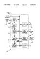
- FIG. 2is a functional block diagram of a find, filter, and eject ("FFE") circuit board according to this invention.
- FIG. 3is a plan view of a defective potato chip enclosed by a bounding box.
- FIG. 4is a simplified functional block diagram of the overall center shot sorting system showing the separate data flow paths for defect centroids and defective item centroids.
- an inspection and sorting system 10includes electronic analysis and control boards embedded on a system bus 12, which is preferably an industry standard VME bus.
- a bus master computer 14 based on an Intel® 386 microprocessorserves as controller of the boards embedded on system bus 12.
- Inspection zone 22is defined by the field of view of a line scanning CCD array camera 24 that is shown scanning items 16 one of which includes a defect 26.
- Camera 24generates red, green, and blue analog pixel signals which are sent to an analog-to-digital converter and camera control (“ADC") board 28.
- the analog pixel signalseach have amplitudes that are proportional to the amount of radiation received by three arrays of CCD transducers sensitive to predetermined bandwidths of radiation, preferably centered on frequencies of red, green, and blue light.
- Camera 24generates analog pixel signals in response to radiation spanning the entire visible spectrum of light but is not limited to the visible spectrum.
- Each color analog pixel signalis digitized to 8-bits and normalized via conventional gain-RAM and digital multiplier techniques.
- the two least-significant bits of each digitized pixel signalare discarded, and the resulting three 6-bit digital pixel data signals are concatenated to form an 18-bit wide stream of digital video words, one word corresponding to each pixel position of each scan of line scanning CCD array camera 24.
- the 18-bit digital video wordsare placed on a digital video bus 30 for analysis and processing to be described later.
- ADC board 28During inspection of items 16 by camera 24, the video data containing defect 26 are placed on digital video bus 30 by ADC board 28.
- Bus master computer 14places the ejector patterns in a memory queue, and in response to roto-pulses from an incremental shaft encoder 36 coupled to conveyor belt 20, the queue is advanced.
- the matching ejection patternhas been advanced to the end of the queue and sent to a defect removal driver board 34.
- a defective item 40is subsequently deflected by a blast of air from the appropriate ejector module or modules 38.
- Acceptable items 16pass undeflected through the region of ejector modules 38 and land on an acceptance conveyor belt 42 or some other collecting means.
- inspection zone 22 of camera 24is displaced downstream from conveyor belt 18 but ahead of ejector modules 38.
- This embodimentreferred to as "off-belt inspection” allows camera 24 to scan items 16 as they are propelled in the air from the end of conveyor belt 18 toward ejector modules 38.
- Off-belt inspectionallows mounting camera 24 below items 16; such camera positioning is beneficial for inspection of certain kinds of items.
- Off-belt inspectionprovides a predictable background color for inspection that prevents dirt and contaminants on conveyor belt 18 from causing anomalous video signals that could lead to sorting errors.
- Control computer 44including a VGA display 46 and a light-pen 48.
- Control computer 44is preferably a PC-AT in which light-pen 48 provides a graphical operator interface for system setup, commands, and parameter adjustments.
- Control computer 44communicates with bus master computer 14 over system bus 12 via a 32-kilobyte dual-port interface memory 50.
- Bus master computer 14either executes various light-pen selected commands or relays these commands to other devices on system bus 12.
- Control computer 44includes a hard disk for storing operator selected setup parameters, product defect histograms, and other initialization data.
- a frame grabber board 52captures sequential words of digital video data from digital video bus 30 and builds up full-color images of items 16 on belt. 18 that are displayed on an RGB monitor 54.
- the operatoruses light-pen 48 to select colors displayed on RGB display 54 that represent acceptable items 16, defects 26, and conveyor belt 18.
- the selected colorsare transferred from frame grabber 52 through a dual-port interface 56 to FFEs 32 by bus master computer 14.
- the selected colorsare used to load color lookup tables on FFEs 32 with data for determining whether items 16 are acceptable or rejectable.
- U.S. Pat. No. 5,085,325 of Jones et al.describes various methods of loading color lookup tables with accept/reject and other data.
- Digital video dataare transferred from ADC board 28 to FFEs 32 on digital video bus 30.
- FFEs 32are multi-purpose image analysis boards, each including a color lookup table ("CLUT") 100 containing accept/reject data loaded according to the above description.
- CLUTcolor lookup table
- the 18-bit words on digital video bus 30act to address CLUT 100, which has an address space of 262,144 locations to accommodate all possible combinations of color addresses.
- the output from CLUT 100is a serial binary data stream of logic 1's and 0's at the 18-bit word rate on digital video bus 30.
- the one bit per eighteen word raterepresents an 18:1 data compression ratio, thereby facilitating subsequent computations.
- FLUT 102has a 16-bit address space and contains 65,536 addressable memory locations.
- the address for FLUT 102is formed by shifting the serial binary data stream from CLUT 100 into a 16-bit shift register 104.
- a 16-bit output bus 105 from shift register 104forms the address for FLUT 102 and consists, at any given time, of the 16 previous data states shifted into 16-bit shift register 104 from CLUT 100.
- Each bit received from CLUT 100corresponds to a sequential 18-bit word on digital video bus 30, and each sequential 18-bit word corresponds to an incremental (pixel sized) location along inspection zone 22 on conveyor belt 18 (FIG. 1).
- the number of sequential 18-bit words generated as a result of each scan of inspection zone 22 by camera 24depends on the number of transducers in each CCD array of camera 24.
- FLUT 102performs a digital filtering operation on the binary data stream.
- the filter function to be performedis selectable by the operator via light-pen 48 from VGA display 46.
- Control computer 44loads FFE 32 with the selected filter data via dual port interface 50, system bus 12, and a dual port interface 106 in FFE 32.
- Preferably there are seven filter selectionsincluding a first selection that does nothing to the binary data stream, a second selection that removes all single 1's and trailing 1's in a group of 1's, and a third selection that removes all single 1's and all grouped pairs of 1's.
- the filtering operation for any given address of FLUT 102has to be based on data states preceding and subsequent to the data bit being examined. This causes delay in the filtering process because bits must be shifted into the address of FLUT 102 before a properly filtered output can be generated. This delay is inherent in the manner in which FLUT 102 is addressed and programmed.
- the most recent data bitis designated the most significant bit (MSB) of the FLUT 102 address
- the 16th prior bitis designated the least significant bit (LSB)
- the 8th bit in the sequenceis designated the bit being "filtered.”
- FLUT 102addresses filter data with "knowledge” of 8 prior bits and the 7 subsequent bits. If the operator selects a filter that removes a single leading "1" and a single trailing "1" from a group of three 1's, the address will have a 1 stored at that memory location, as shown below. ##STR1##
- the output of FLUT 102is also a sequential binary data stream with a delay of 8 bits with respect to the binary data stream from CLUT 100.
- This delayed, filtered binary data streamis written into an image memory 108 on FFE 32.
- FFE 32also includes a graphic signal processor ("GSP") 110 such as type 34010 available from Texas, Instruments, Inc., Dallas, Tex.
- GSP 110graphic signal processor
- Image memory 108is within the address space of GSP 110, which forms the "image" of the filtered serial data by storing the data as a raster of line scans.
- GSP 110then inspects image memory 108 for horizontal and vertical groupings of 1's that delineate defects 26 in items 16 being scanned by camera 24.
- each line of data in image memory 108is traversed by GSP 110 under control of a program stored in a program memory 112.
- the programcauses GSP 110 to search image memory 108 for contiguous horizontal groupings of 1's.
- the minimum and maximum X-coordinate values of the leading and trailing edge of the groupingare stored in a defect list in dual port interface 106 and are assigned a defect number.
- the area (number of 1's) for that defectis recorded by storing the number of contiguous 1's in the grouping. Subsequent groups of 1's on the same line are treated alike and assigned the next sequential defect number in the defect list.
- the searching processis repeated for subsequent horizontal lines in image memory 108.
- the X MIN and X MAX values of the subsequent lineare compared to those in the defect list and where an overlap occurs, the grouping in the subsequent line is assigned the same defect number. Where overlap occurs and the grouping in the subsequent line has a larger X MAX or a smaller X MIN , the defect list values for X MIN , X MAX , Y MIN , and Y MAX are updated.
- the corresponding defect areais also incremented by adding the number of 1's in the grouping of the subsequent line to the area number for the previous line.
- the defect listcontains the minimum and maximum X- and Y-coordinate values inside of which lie the defects and the areas of the defects.
- the minimum and maximum X- and Y-coordinate valuesalso form a "defect-bounding box" that surrounds each defect.
- the geometric centers ("centroids") of the defect-bounding boxesare computed as (X MIN +X MAX )/2 and (Y MIN +Y MAX )/2.
- a preferred format for the defect listis:
- GSP 110computes a defect centroid for each item in the defect list and builds a defect centroid list.
- a defects ready interrupt signal 114is generated by GSP 110 to alert bus master computer 14 that the defect centroid list is ready.
- the defect listcan be sent to a first-in-first-out ("FIFO") memory for transmission to another FFE board in a manner to be described later.
- Bus master computer 14then reads the defect centroid list from program memory 112 via dual port interface 106 and maps the defect centroid X- and y-coordinate values into ejector patterns for subsequent transmittal to defect removal driver 34.
- Defect size (area) limitsare selected by the operator via light-pen 48. Selected sizes are compared by GSP 110 with the defect areas listed in the defect list to determine which defects are sufficient large to warrant computing and listing defect centroids for sending to bus master computer 14 and mapping into ejector patterns.
- FFE 32If defects meeting multiple color and size criteria are to be removed, a separate FFE 32 is used for each combination of defect color and size. For example, FFE 32A detects small black defects, FFE 32B detects larger brown defects, FFE 32C detects green stem-sized defects, and FFE 32D detects yellow soft-center sized defects.
- Each FFE board 32locates, lists, and reports the centroids of defects scanned into its own image memory 108.
- Each image memory 108contains 128 scan lines of memory with 1024 bits per line. Defective colors in image memory 108 are preferably represented by a logic "1" bit and acceptable colors are represented by a logic "0" bit. Alternately, the opposite logical sense could be used.
- image memory 108is divided into frames.
- GSP 110is programmed so that FLUT 102 and GSP 110 are never accessing scan lines in the same frame at the same time.
- FLUT 102is designed to send a "new-frame" interrupt signal to GSP 110. Using this interrupt signal, the GSP program knows when to access the next frame of data. GSP 110 also notifies the program when it must abandon a previous frame of data. The number of lines in a frame is programmable.
- the defect finding programcan process data in image memory 108 on a line-by-line basis because only two scan lines are needed in image memory at any one time.
- GSP 110is processing one scan line, FLUT 102 is writing to the other.
- GSP 110is programmed to generate a "new-frame" interrupt signal on every scan line and the frame size is set to "one.”
- the defect X-, Y-coordinate locationis written to dual port memory 106.
- the GSP 110is programmed to generate defects ready interrupt signal 114.
- bus master computer 14cannot receive a defect centroid list from dual port interface 106 while GSP 110 is adding new defects to the same list.
- dual port interface 106is divided into two halves.
- Defects ready interrupt signal 114also informs master computer 14 which half of dual port interface 106 to access.
- GSP 110then uses the other half to write the next defect centroid list.
- GSP 110"ping-pongs" between the two halves of dual port interface 106.
- FFEs 32also contain a set of bits-per-line counters 116 (one for each scan line) for counting the number of defect bits in each scan line of image memory 108. Before GSP 110 processes bits in any scan line, the program reads the bits-per-line counter 116 for the particular scan line and ignores the scan line if the number of defect bits does not exceed a predetermined number.
- One particular embodiment of this inventionis directed toward center shot sorting of items 16 such as flat items (e.g., potato chips) or non-flat items (e.g., whole strawberries and radishes with stems).
- a "master-FFE" 32A'having the same hardware as FFEs 32, is programmed to detect entire items by detecting everything that is not substantially belt-colored (i.e., detecting the entire item as though it were a defect).
- FFEs 32are programmed to detect defects in the items as described above and to communicate the defect locations over an FFE bus 118 that is connected to a FIFO interface 120 on FFEs 32 and master-FFE 32A'.
- dual port interfaces 106 of FFEs 32are not used.
- Master-FFE 32A'builds a stored representation of the image of each item by storing in image memory 108 a logic 1 at each X- and Y-coordinate location that corresponds to an actual location on each item.
- the X-coordinatecorresponds to the scanning direction for line scan camera 24, and the Y-coordinate represents the direction in which items 16 are moved past camera 24.
- the value of Y MAXis preferably not more than 64 scan lines greater than the value of Y MIN .
- the number 64is another convention, and the only limitation on Y MAX is that it represent a distance that is less than that between inspection zone 22 and ejector modules 38.
- FIG. 3shows the X- and Y-coordinates defining an item-bounding box 150 around an exemplary potato chip 152 having a defect 154 and an item centroid 156.
- FFE 32Bdetects defect 154 on potato chip 152.
- FFE 32Bbuilds a defect list that includes a defect centroid 158.
- the X- and Y-coordinates of defect centroid 158are sent from FFE 32B to master-FFE 32A' over FFE bus 118 and are stored in a queue (not shown) in FIFO interface 120 of master-FFE 32A'.
- master-FFE 32A'detects all potato chips on conveyor belt 18 and stores their image data in image memory 108
- master-FFE 32A'computes item centroids 156 for only those potato chips having defect centroids 158 stored in FIFO interface 120. Specifically, for each defect centroid 158 coordinate pair stored in FIFO interface 120, master-FFE 32A' identifies the corresponding image coordinates for potato chip 152 stored in its image memory 108 and uses defect centroid 158 as a "trigger" to compute the X max , X min , Y max , Y min item bounding box 150 coordinates and item centroid 156 coordinates of potato chip 152.
- Item centroid 156is computed by master-FFE 32A' as the average of the respective X- and Y-coordinate limits of item-bounding box 150:
- item centroid 156may be determined by summing the individual coordinate positions representing an item bounded by item-bounding box 150 and dividing the sum by the number of such coordinates:
- an item such as potato chip 152can have multiple defects each of different colors and sizes.
- FFE 32Bdetects defect 154 having a color B and centroid 158 and that FFE 32C detects defect 160 having a color C and a centroid 162.
- FFE 32Bgenerates a color B defect list 170 including centroid 158 coordinates X B158 , Y B158 of defect 154 and FFE 32C generates a color C defect list 172 including centroid 162 coordinates X C162 , Y C162 of defect 160.
- Defect lists 170 and 172are sent to master-FFE 32A' over FFE bus 118 and stored in the FIFO interface queue as described above.
- Potato chip 152is represented by a group of logic 1's stored in image memory 108 of master-FFE 32A'.
- master-FFE 32A'is triggered by centroid coordinates X B158 , Y B158 , bounding box 150 and centroid 156 are computed for potato chip 152, and the logic 1's representing potato chip 152 are cleared to logic O's.
- the clearing operationeliminates redundant determinations of centroid 156 of potato chip 152. If subsequent defect centroid coordinates, such as X C162 , Y C162 , are otherwise capable of triggering master-FFE 32A' the absence of logic 1's at that corresponding location in image memory 108 prevents a redundant determination of centroid 156 of potato chip 152.
- centroid 156 coordinates X B156 ,Y B156 of potato chip 152are added to a defective item list 174 stored in program memory 112 (FIG. 2) of master-FFE 32A'.
- An acceptable itemwill be detected by master-FFE 32A' but no defects associated with the acceptable item will be detected by FFEs 32. As a result, no defect centroid will have coordinates lying within the group of logic 1's that represent the acceptable item. Therefore, master-FFE 32A' will not be triggered to generate a centroid.
- Defective item list 174cannot be completed until master-FFE 32A' has a complete frame of data in image memory 108. For this reason, master-FFE 32A' lags approximately one frame (64 scan lines) behind FFEs 32. FFEs 32 have their defect lists, such as 170 and 174, ready every 64th scan line. Master-FFE 32A' receives a new frame interrupt every 64 scan lines. This interrupt indicates that all defects detected by all FFEs 32 during the previous frame, are listed and ready for master-FFE 32A'.
- Master-FFE 32A'then reads out its FIFO interface 120, generates defective item list 174, circulates through all FFEs 32, including 32A' clearing the contents of each FIFO interface 120, and generates defects ready interrupt signal 114 to alert bus master computer 14 that defective item list 174 is ready.
- Bus master computer 14then reads defective item list 174 via dual port interface 106 of master-FFE 32A' and maps the various item centroid X- and y-coordinate values of defective item list 174 into ejector patterns for transmittal to defect removal driver 34.
Landscapes
- Engineering & Computer Science (AREA)
- Multimedia (AREA)
- Investigating Materials By The Use Of Optical Means Adapted For Particular Applications (AREA)
Abstract
Description
______________________________________ DEFECT X.sub.MIN X.sub.MAX Y.sub.MIN Y.sub.MAX AREA (defect) 2 . . . n ______________________________________
X.sub.CENTROID =(X.sub.MAX +X.sub.MIN)/2
Y.sub.CENTROID =(Y.sub.MAX +Y.sub.MIN)/2.
X.sub.CENTROID =Σ.sub.i=1-N X.sub.i /N
Y.sub.CENTROID =Σ.sub.i=1-N Y.sub.i /N
Claims (21)
Priority Applications (1)
| Application Number | Priority Date | Filing Date | Title |
|---|---|---|---|
| US08/194,090US5398818A (en) | 1992-05-29 | 1994-02-09 | Center shot sorting system and method |
Applications Claiming Priority (2)
| Application Number | Priority Date | Filing Date | Title |
|---|---|---|---|
| US07/890,966US5305894A (en) | 1992-05-29 | 1992-05-29 | Center shot sorting system and method |
| US08/194,090US5398818A (en) | 1992-05-29 | 1994-02-09 | Center shot sorting system and method |
Related Parent Applications (1)
| Application Number | Title | Priority Date | Filing Date |
|---|---|---|---|
| US07/890,966DivisionUS5305894A (en) | 1992-05-29 | 1992-05-29 | Center shot sorting system and method |
Publications (1)
| Publication Number | Publication Date |
|---|---|
| US5398818Atrue US5398818A (en) | 1995-03-21 |
Family
ID=25397397
Family Applications (2)
| Application Number | Title | Priority Date | Filing Date |
|---|---|---|---|
| US07/890,966Expired - LifetimeUS5305894A (en) | 1992-05-29 | 1992-05-29 | Center shot sorting system and method |
| US08/194,090Expired - LifetimeUS5398818A (en) | 1992-05-29 | 1994-02-09 | Center shot sorting system and method |
Family Applications Before (1)
| Application Number | Title | Priority Date | Filing Date |
|---|---|---|---|
| US07/890,966Expired - LifetimeUS5305894A (en) | 1992-05-29 | 1992-05-29 | Center shot sorting system and method |
Country Status (1)
| Country | Link |
|---|---|
| US (2) | US5305894A (en) |
Cited By (23)
| Publication number | Priority date | Publication date | Assignee | Title |
|---|---|---|---|---|
| WO1997018045A1 (en)* | 1995-11-15 | 1997-05-22 | Rosebay Terrace Pty. Ltd. | Automated sorting apparatus and system |
| US5689580A (en)* | 1993-06-21 | 1997-11-18 | Japan Elanco Company Limited | Printed letter inspecting apparatus for solid objects |
| US6250472B1 (en) | 1999-04-29 | 2001-06-26 | Advanced Sorting Technologies, Llc | Paper sorting system |
| US6286655B1 (en) | 1999-04-29 | 2001-09-11 | Advanced Sorting Technologies, Llc | Inclined conveyor |
| US6369882B1 (en) | 1999-04-29 | 2002-04-09 | Advanced Sorting Technologies Llc | System and method for sensing white paper |
| US6374998B1 (en) | 1999-04-29 | 2002-04-23 | Advanced Sorting Technologies Llc | “Acceleration conveyor” |
| US6504124B1 (en) | 1998-10-30 | 2003-01-07 | Magnetic Separation Systems, Inc. | Optical glass sorting machine and method |
| US20040094050A1 (en)* | 2002-11-13 | 2004-05-20 | Ackley Machine Corporation | Laser unit, inspection unit, method for inspecting and accepting/removing specified pellet-shaped articles from a conveyer mechanism, and pharmaceutical article |
| US20040197012A1 (en)* | 2002-11-07 | 2004-10-07 | Bourg Wilfred Marcellien | Method for on-line machine vision measurement, monitoring and control of organoleptic properties of products for on-line manufacturing processes |
| US20040251178A1 (en)* | 2002-08-12 | 2004-12-16 | Ecullet | Method of and apparatus for high speed, high quality, contaminant removal and color sorting of glass cullet |
| US7019822B1 (en) | 1999-04-29 | 2006-03-28 | Mss, Inc. | Multi-grade object sorting system and method |
| US20060124511A1 (en)* | 2000-10-19 | 2006-06-15 | Eco-Shred Ltd. | Optical paper sorting method device and apparatus |
| US20060219612A1 (en)* | 2005-01-28 | 2006-10-05 | Satake Usa, Inc. | Multiport ejector for use with sorter |
| US20070278139A1 (en)* | 2004-03-02 | 2007-12-06 | Qinetiq Limited | Separating Device and Sorting Apparatus With Two-Dimensionals Array of Nozzles and Method of Sorting Objects |
| US7355140B1 (en) | 2002-08-12 | 2008-04-08 | Ecullet | Method of and apparatus for multi-stage sorting of glass cullets |
| US20100096299A1 (en)* | 2006-12-08 | 2010-04-22 | Dirk Adams | Method and Device for Sorting Products |
| US20100230330A1 (en)* | 2009-03-16 | 2010-09-16 | Ecullet | Method of and apparatus for the pre-processing of single stream recyclable material for sorting |
| US20110100884A1 (en)* | 2001-10-02 | 2011-05-05 | Emerging Acquisitions, Llc | De-inking screen with air knife |
| US20120204918A1 (en)* | 2009-11-19 | 2012-08-16 | Unitec S.P.A. | Plant for Cleaning Bins Used for Vegetable Produce |
| US8373081B2 (en) | 2010-06-01 | 2013-02-12 | Ackley Machine Corporation | Inspection system |
| US8436268B1 (en) | 2002-08-12 | 2013-05-07 | Ecullet | Method of and apparatus for type and color sorting of cullet |
| US8714362B2 (en) | 2011-11-22 | 2014-05-06 | Key Technology, Inc. | Sorting apparatus |
| US9027759B2 (en) | 2011-11-22 | 2015-05-12 | Key Technology, Inc. | Sorting apparatus |
Families Citing this family (16)
| Publication number | Priority date | Publication date | Assignee | Title |
|---|---|---|---|---|
| US5318173A (en)* | 1992-05-29 | 1994-06-07 | Simco/Ramic Corporation | Hole sorting system and method |
| US5305894A (en)* | 1992-05-29 | 1994-04-26 | Simco/Ramic Corporation | Center shot sorting system and method |
| GB2273154B (en)* | 1992-12-02 | 1996-12-11 | Buehler Ag | Method for cleaning and sorting bulk material |
| US5520290A (en)* | 1993-12-30 | 1996-05-28 | Huron Valley Steel Corporation | Scrap sorting system |
| JP3275280B2 (en)* | 1994-10-07 | 2002-04-15 | 株式会社サタケ | Raw material supply device for granular material color sorter |
| AR002082A1 (en)* | 1995-05-25 | 1998-01-07 | Gillette Co | METHOD TO PRODUCE A CUTTING EDGE IN A METAL STRIP AND THE APPLIANCE TO PERFORM IT |
| US5732147A (en)* | 1995-06-07 | 1998-03-24 | Agri-Tech, Inc. | Defective object inspection and separation system using image analysis and curvature transformation |
| BE1011137A3 (en)* | 1997-04-24 | 1999-05-04 | Bruynooghe Constructie Nv | Method for sorting vegetables and device that applies this method |
| US6243164B1 (en) | 1998-07-13 | 2001-06-05 | Electro Scientific Industries | Method and system for determining lead coplanarity |
| US6727452B2 (en)* | 2002-01-03 | 2004-04-27 | Fmc Technologies, Inc. | System and method for removing defects from citrus pulp |
| NL2005216C2 (en) | 2010-08-11 | 2012-02-20 | Optiserve B V | SORTING DEVICE AND METHOD FOR SEPARATING PRODUCTS IN A BULK FLOW OF NON-HOMOGENIC PRODUCTS. |
| BE1020295A3 (en)* | 2011-11-16 | 2013-07-02 | Acro Khlim | METHOD FOR SORTING OBJECTS AND SORTING DEVICES THEREFOR |
| JP6098881B2 (en)* | 2013-05-30 | 2017-03-22 | パナソニックIpマネジメント株式会社 | Sorting device |
| US9785851B1 (en) | 2016-06-30 | 2017-10-10 | Huron Valley Steel Corporation | Scrap sorting system |
| EP4301525A4 (en)* | 2021-03-04 | 2024-12-25 | Ishitva Robotic Systems Pvt Ltd | PNEUMATIC SORTING UNIT |
| CN114082674B (en)* | 2021-10-22 | 2023-10-10 | 江苏大学 | A color sorting method for small-grain agricultural products based on surface scanning, line scanning, and photoelectric characteristics |
Citations (6)
| Publication number | Priority date | Publication date | Assignee | Title |
|---|---|---|---|---|
| US4344539A (en)* | 1978-05-05 | 1982-08-17 | Lockett James F | Universal sorting apparatus |
| US4759074A (en)* | 1986-10-28 | 1988-07-19 | General Motors Corporation | Method for automatically inspecting parts utilizing machine vision and system utilizing same |
| US5058174A (en)* | 1989-09-14 | 1991-10-15 | Carroll Thomas M | System and method for generating a pattern from an image |
| US5085325A (en)* | 1988-03-08 | 1992-02-04 | Simco/Ramic Corporation | Color sorting system and method |
| US5148923A (en)* | 1990-02-19 | 1992-09-22 | Sortex Limited | Apparatus for sorting or otherwise treating objects |
| US5305894A (en)* | 1992-05-29 | 1994-04-26 | Simco/Ramic Corporation | Center shot sorting system and method |
Family Cites Families (11)
| Publication number | Priority date | Publication date | Assignee | Title |
|---|---|---|---|---|
| US4493420A (en)* | 1981-01-29 | 1985-01-15 | Lockwood Graders (U.K.) Limited | Method and apparatus for detecting bounded regions of images, and method and apparatus for sorting articles and detecting flaws |
| US4493105A (en)* | 1982-03-31 | 1985-01-08 | General Electric Company | Method and apparatus for visual image processing |
| US4600105A (en)* | 1983-03-23 | 1986-07-15 | Sphere Investments Limited | Method and apparatus for sorting objects of ore by monitoring reflected radiation |
| USRE33357E (en)* | 1983-05-27 | 1990-09-25 | Key Technology, Inc. | Optical inspection apparatus for moving articles |
| US4645080A (en)* | 1984-07-02 | 1987-02-24 | Pennwalt Corporation | Method and apparatus for grading non-orienting articles |
| JPH0690149B2 (en)* | 1986-01-31 | 1994-11-14 | 東洋ガラス株式会社 | Transparency inspection device |
| US4741042A (en)* | 1986-12-16 | 1988-04-26 | Cornell Research Foundation, Inc. | Image processing system for detecting bruises on fruit |
| US4947449A (en)* | 1987-03-31 | 1990-08-07 | Nippon Sheet Glass Co., Ltd. | Apparatus for simultaneously extracting various types of projection features of an image |
| JPH01249181A (en)* | 1988-03-31 | 1989-10-04 | Tdk Corp | Parts sorting method for automatic appearance screening machine for chip parts |
| US5058177A (en)* | 1988-01-04 | 1991-10-15 | Motorola, Inc. | Method for inspection of protruding features |
| CA1251863A (en)* | 1988-02-29 | 1989-03-28 | Kevin Mccarthy | Fish sorting machine |
- 1992
- 1992-05-29USUS07/890,966patent/US5305894A/ennot_activeExpired - Lifetime
- 1994
- 1994-02-09USUS08/194,090patent/US5398818A/ennot_activeExpired - Lifetime
Patent Citations (6)
| Publication number | Priority date | Publication date | Assignee | Title |
|---|---|---|---|---|
| US4344539A (en)* | 1978-05-05 | 1982-08-17 | Lockett James F | Universal sorting apparatus |
| US4759074A (en)* | 1986-10-28 | 1988-07-19 | General Motors Corporation | Method for automatically inspecting parts utilizing machine vision and system utilizing same |
| US5085325A (en)* | 1988-03-08 | 1992-02-04 | Simco/Ramic Corporation | Color sorting system and method |
| US5058174A (en)* | 1989-09-14 | 1991-10-15 | Carroll Thomas M | System and method for generating a pattern from an image |
| US5148923A (en)* | 1990-02-19 | 1992-09-22 | Sortex Limited | Apparatus for sorting or otherwise treating objects |
| US5305894A (en)* | 1992-05-29 | 1994-04-26 | Simco/Ramic Corporation | Center shot sorting system and method |
Cited By (57)
| Publication number | Priority date | Publication date | Assignee | Title |
|---|---|---|---|---|
| US5689580A (en)* | 1993-06-21 | 1997-11-18 | Japan Elanco Company Limited | Printed letter inspecting apparatus for solid objects |
| WO1997018045A1 (en)* | 1995-11-15 | 1997-05-22 | Rosebay Terrace Pty. Ltd. | Automated sorting apparatus and system |
| US6149016A (en)* | 1995-11-15 | 2000-11-21 | Rosebay Terrace Pty Ltd. | Automated sorting apparatus and system |
| US6504124B1 (en) | 1998-10-30 | 2003-01-07 | Magnetic Separation Systems, Inc. | Optical glass sorting machine and method |
| US7499172B2 (en) | 1999-04-29 | 2009-03-03 | Mss, Inc. | Multi-grade object sorting system and method |
| US6286655B1 (en) | 1999-04-29 | 2001-09-11 | Advanced Sorting Technologies, Llc | Inclined conveyor |
| US6369882B1 (en) | 1999-04-29 | 2002-04-09 | Advanced Sorting Technologies Llc | System and method for sensing white paper |
| US6374998B1 (en) | 1999-04-29 | 2002-04-23 | Advanced Sorting Technologies Llc | “Acceleration conveyor” |
| US6570653B2 (en) | 1999-04-29 | 2003-05-27 | Advanced Sorting Technologies, Llc | System and method for sensing white paper |
| US6778276B2 (en) | 1999-04-29 | 2004-08-17 | Advanced Sorting Technologies Llc | System and method for sensing white paper |
| US6891119B2 (en) | 1999-04-29 | 2005-05-10 | Advanced Sorting Technologies, Llc | Acceleration conveyor |
| US7019822B1 (en) | 1999-04-29 | 2006-03-28 | Mss, Inc. | Multi-grade object sorting system and method |
| US20070002326A1 (en)* | 1999-04-29 | 2007-01-04 | Doak Arthur G | Multi-grade object sorting system and method |
| USRE42090E1 (en) | 1999-04-29 | 2011-02-01 | Mss, Inc. | Method of sorting waste paper |
| US6250472B1 (en) | 1999-04-29 | 2001-06-26 | Advanced Sorting Technologies, Llc | Paper sorting system |
| US20090032445A1 (en)* | 1999-04-29 | 2009-02-05 | Mss, Inc. | Multi-Grade Object Sorting System And Method |
| US8411276B2 (en) | 1999-04-29 | 2013-04-02 | Mss, Inc. | Multi-grade object sorting system and method |
| US7173709B2 (en) | 2000-02-04 | 2007-02-06 | Mss, Inc. | Multi-grade object sorting system and method |
| US7081594B1 (en)* | 2000-10-19 | 2006-07-25 | Eco-Shred Ltd. | Optical paper sorting method device and apparatus |
| US20060124511A1 (en)* | 2000-10-19 | 2006-06-15 | Eco-Shred Ltd. | Optical paper sorting method device and apparatus |
| US20110100884A1 (en)* | 2001-10-02 | 2011-05-05 | Emerging Acquisitions, Llc | De-inking screen with air knife |
| US8857621B2 (en)* | 2001-10-02 | 2014-10-14 | Emerging Acquisitions, Llc | De-inking screen with air knife |
| US8436268B1 (en) | 2002-08-12 | 2013-05-07 | Ecullet | Method of and apparatus for type and color sorting of cullet |
| US7351929B2 (en) | 2002-08-12 | 2008-04-01 | Ecullet | Method of and apparatus for high speed, high quality, contaminant removal and color sorting of glass cullet |
| US7355140B1 (en) | 2002-08-12 | 2008-04-08 | Ecullet | Method of and apparatus for multi-stage sorting of glass cullets |
| US20080128336A1 (en)* | 2002-08-12 | 2008-06-05 | Farook Afsari | Method of and apparatus for high speed, high quality, contaminant removal and color sorting of glass cullet |
| US20040251178A1 (en)* | 2002-08-12 | 2004-12-16 | Ecullet | Method of and apparatus for high speed, high quality, contaminant removal and color sorting of glass cullet |
| US7660440B2 (en) | 2002-11-07 | 2010-02-09 | Frito-Lay North America, Inc. | Method for on-line machine vision measurement, monitoring and control of organoleptic properties of products for on-line manufacturing processes |
| US20040197012A1 (en)* | 2002-11-07 | 2004-10-07 | Bourg Wilfred Marcellien | Method for on-line machine vision measurement, monitoring and control of organoleptic properties of products for on-line manufacturing processes |
| US20060268264A1 (en)* | 2002-11-13 | 2006-11-30 | Ackley Machine Corporation | Laser system for pellet-shaped articles |
| US8072590B2 (en) | 2002-11-13 | 2011-12-06 | Ackley Machine Corporation | Laser system for pellet-shaped articles |
| US7701568B2 (en) | 2002-11-13 | 2010-04-20 | Ackley Machine Corporation | Laser system for pellet-shaped articles |
| US7456946B2 (en) | 2002-11-13 | 2008-11-25 | Ackley Machine Corporation | Laser system for pellet-shaped articles |
| US20040094050A1 (en)* | 2002-11-13 | 2004-05-20 | Ackley Machine Corporation | Laser unit, inspection unit, method for inspecting and accepting/removing specified pellet-shaped articles from a conveyer mechanism, and pharmaceutical article |
| US7102741B2 (en) | 2002-11-13 | 2006-09-05 | Ackley Machine Corporation | Printing/inspection unit, method and apparatus for printing and/or inspecting and accepting/removing specified pellet-shaped articles from a conveyer mechanism |
| US8269958B2 (en) | 2002-11-13 | 2012-09-18 | Ackley Machine Corporation | Laser system for pellet-shaped articles |
| US20090090848A1 (en)* | 2002-11-13 | 2009-04-09 | Ackley Machine Corporation | Laser system for pellet-shaped articles |
| US20070278139A1 (en)* | 2004-03-02 | 2007-12-06 | Qinetiq Limited | Separating Device and Sorting Apparatus With Two-Dimensionals Array of Nozzles and Method of Sorting Objects |
| US7775369B2 (en)* | 2004-03-02 | 2010-08-17 | Qinetiq Limited | Separating device and sorting apparatus with two-dimensionals array of nozzles and method of sorting objects |
| US20060219612A1 (en)* | 2005-01-28 | 2006-10-05 | Satake Usa, Inc. | Multiport ejector for use with sorter |
| US20100096299A1 (en)* | 2006-12-08 | 2010-04-22 | Dirk Adams | Method and Device for Sorting Products |
| US9006599B2 (en)* | 2006-12-08 | 2015-04-14 | Visys | Method and device for sorting products |
| US20100230330A1 (en)* | 2009-03-16 | 2010-09-16 | Ecullet | Method of and apparatus for the pre-processing of single stream recyclable material for sorting |
| US20120204918A1 (en)* | 2009-11-19 | 2012-08-16 | Unitec S.P.A. | Plant for Cleaning Bins Used for Vegetable Produce |
| US9415429B2 (en)* | 2009-11-19 | 2016-08-16 | Unitec S.P.A. | Plant for cleaning bins used for vegetable produce |
| US9259766B2 (en) | 2010-06-01 | 2016-02-16 | Ackley Machine Corporation | Inspection system |
| US8373081B2 (en) | 2010-06-01 | 2013-02-12 | Ackley Machine Corporation | Inspection system |
| US9101962B2 (en) | 2010-06-01 | 2015-08-11 | Ackley Machine Corporation | Inspection system |
| US8770413B2 (en) | 2010-06-01 | 2014-07-08 | Ackley Machine Corporation | Inspection system |
| US9468948B2 (en) | 2010-06-01 | 2016-10-18 | Ackley Machine Corporation | Inspection system |
| US9757772B2 (en) | 2010-06-01 | 2017-09-12 | Ackley Machine Corporation | Inspection system |
| US10201837B2 (en) | 2010-06-01 | 2019-02-12 | Ackley Machine Corporation | Inspection system |
| US10518294B2 (en) | 2010-06-01 | 2019-12-31 | Ackley Machine Corporation | Inspection system |
| US10919076B2 (en) | 2010-06-01 | 2021-02-16 | Ackley Machine Corporation | Inspection system |
| US11897001B2 (en) | 2010-06-01 | 2024-02-13 | Ackley Machine Corporation | Inspection system |
| US9027759B2 (en) | 2011-11-22 | 2015-05-12 | Key Technology, Inc. | Sorting apparatus |
| US8714362B2 (en) | 2011-11-22 | 2014-05-06 | Key Technology, Inc. | Sorting apparatus |
Also Published As
| Publication number | Publication date |
|---|---|
| US5305894A (en) | 1994-04-26 |
Similar Documents
| Publication | Publication Date | Title |
|---|---|---|
| US5398818A (en) | Center shot sorting system and method | |
| US5409119A (en) | Hole sorting system and method | |
| US5862919A (en) | High throughput sorting system | |
| US4759074A (en) | Method for automatically inspecting parts utilizing machine vision and system utilizing same | |
| CA2392987C (en) | Multi-resolution label locator | |
| EP0597639B1 (en) | Non-contact surface flaw detection | |
| EP1083007B1 (en) | Method and apparatus for sorting granular objects with at least two different threshold levels | |
| EP0267790A2 (en) | Method and apparatus for sorting articles | |
| EP0227404B1 (en) | Sorting | |
| EP0658262B1 (en) | Method and device for automatic evaluation of cereal grains and other granular products | |
| US5223917A (en) | Product discrimination system | |
| JP2003518300A5 (en) | ||
| WO1997037780A1 (en) | Color sorting system | |
| JPH01194079A (en) | Printing inspection instrument using ink jet printer | |
| EP0289500A1 (en) | Inspection apparatus | |
| EP4115996B1 (en) | Optical sorting machine | |
| US6445817B1 (en) | Apparatus for counting color transitions and areas in real time camera images | |
| JP3517292B2 (en) | Bulk material optical sorting method | |
| EP0377478B1 (en) | Apparatus for inspecting bulk goods | |
| US5689580A (en) | Printed letter inspecting apparatus for solid objects | |
| JPH09318547A (en) | Appearance inspection method and apparatus for farm product | |
| JP2001239221A (en) | Image forming device and assorting/classifying/judging device used for assorting of agricultural product | |
| JPH0773694B2 (en) | Vegetable and fruit sorter | |
| JP2024101318A (en) | Measurement device and selection apparatus | |
| JP2024076783A (en) | Measuring Equipment and Sorting Machines |
Legal Events
| Date | Code | Title | Description |
|---|---|---|---|
| STCF | Information on status: patent grant | Free format text:PATENTED CASE | |
| AS | Assignment | Owner name:SRC VISION, INC., OREGON Free format text:CHANGE OF NAME;ASSIGNOR:SRC VISION, INC.;REEL/FRAME:008215/0563 Effective date:19951006 | |
| FPAY | Fee payment | Year of fee payment:4 | |
| FEPP | Fee payment procedure | Free format text:PAYOR NUMBER ASSIGNED (ORIGINAL EVENT CODE: ASPN); ENTITY STATUS OF PATENT OWNER: SMALL ENTITY | |
| AS | Assignment | Owner name:KEY TECHNOLOGY, INC., WASHINGTON Free format text:ASSIGNMENT OF ASSIGNORS INTEREST;ASSIGNOR:SRC VISION, INC.;REEL/FRAME:011390/0629 Effective date:20001130 | |
| AS | Assignment | Owner name:BANNER BANK, WASHINGTON Free format text:SECURITY AGREEMENT;ASSIGNOR:KEY TECHNOLOGY, INC.;REEL/FRAME:013203/0587 Effective date:20020809 | |
| FPAY | Fee payment | Year of fee payment:8 | |
| REMI | Maintenance fee reminder mailed | ||
| FPAY | Fee payment | Year of fee payment:12 | |
| AS | Assignment | Owner name:KEY TECHNOLOGY, INC., WASHINGTON Free format text:TERMINATION OF SECURITY AGREEMENT;ASSIGNOR:BANNER BANK;REEL/FRAME:019699/0375 Effective date:20070807 | |
| AS | Assignment | Owner name:PNC BANK, NATIONAL ASSOCIATION, CALIFORNIA Free format text:SECURITY INTEREST;ASSIGNOR:KEY TECHNOLOGY, INC.;REEL/FRAME:036159/0166 Effective date:20150720 | |
| AS | Assignment | Owner name:KEY TECHNOLOGY, INC., WASHINGTON Free format text:RELEASE BY SECURED PARTY;ASSIGNOR:PNC BANK, NATIONAL ASSOCIATION;REEL/FRAME:045667/0619 Effective date:20180320 |