US5398691A - Method and apparatus for three-dimensional translumenal ultrasonic imaging - Google Patents
Method and apparatus for three-dimensional translumenal ultrasonic imagingDownload PDFInfo
- Publication number
- US5398691A US5398691AUS08/116,293US11629393AUS5398691AUS 5398691 AUS5398691 AUS 5398691AUS 11629393 AUS11629393 AUS 11629393AUS 5398691 AUS5398691 AUS 5398691A
- Authority
- US
- United States
- Prior art keywords
- ultrasonic
- probe
- transducer
- scanning
- coordinate system
- Prior art date
- Legal status (The legal status is an assumption and is not a legal conclusion. Google has not performed a legal analysis and makes no representation as to the accuracy of the status listed.)
- Expired - Lifetime
Links
Images


Classifications
- A—HUMAN NECESSITIES
- A61—MEDICAL OR VETERINARY SCIENCE; HYGIENE
- A61B—DIAGNOSIS; SURGERY; IDENTIFICATION
- A61B1/00—Instruments for performing medical examinations of the interior of cavities or tubes of the body by visual or photographical inspection, e.g. endoscopes; Illuminating arrangements therefor
- A61B1/005—Flexible endoscopes
- A61B1/0051—Flexible endoscopes with controlled bending of insertion part
- A61B1/0052—Constructional details of control elements, e.g. handles
- A—HUMAN NECESSITIES
- A61—MEDICAL OR VETERINARY SCIENCE; HYGIENE
- A61B—DIAGNOSIS; SURGERY; IDENTIFICATION
- A61B5/00—Measuring for diagnostic purposes; Identification of persons
- A61B5/06—Devices, other than using radiation, for detecting or locating foreign bodies ; Determining position of diagnostic devices within or on the body of the patient
- A61B5/061—Determining position of a probe within the body employing means separate from the probe, e.g. sensing internal probe position employing impedance electrodes on the surface of the body
- A61B5/062—Determining position of a probe within the body employing means separate from the probe, e.g. sensing internal probe position employing impedance electrodes on the surface of the body using magnetic field
- A—HUMAN NECESSITIES
- A61—MEDICAL OR VETERINARY SCIENCE; HYGIENE
- A61B—DIAGNOSIS; SURGERY; IDENTIFICATION
- A61B8/00—Diagnosis using ultrasonic, sonic or infrasonic waves
- A61B8/12—Diagnosis using ultrasonic, sonic or infrasonic waves in body cavities or body tracts, e.g. by using catheters
- A—HUMAN NECESSITIES
- A61—MEDICAL OR VETERINARY SCIENCE; HYGIENE
- A61B—DIAGNOSIS; SURGERY; IDENTIFICATION
- A61B8/00—Diagnosis using ultrasonic, sonic or infrasonic waves
- A61B8/44—Constructional features of the ultrasonic, sonic or infrasonic diagnostic device
- A61B8/4444—Constructional features of the ultrasonic, sonic or infrasonic diagnostic device related to the probe
- A61B8/445—Details of catheter construction
- A—HUMAN NECESSITIES
- A61—MEDICAL OR VETERINARY SCIENCE; HYGIENE
- A61B—DIAGNOSIS; SURGERY; IDENTIFICATION
- A61B8/00—Diagnosis using ultrasonic, sonic or infrasonic waves
- A61B8/44—Constructional features of the ultrasonic, sonic or infrasonic diagnostic device
- A61B8/4444—Constructional features of the ultrasonic, sonic or infrasonic diagnostic device related to the probe
- A61B8/4461—Features of the scanning mechanism, e.g. for moving the transducer within the housing of the probe
- A61B8/4466—Features of the scanning mechanism, e.g. for moving the transducer within the housing of the probe involving deflection of the probe
- A—HUMAN NECESSITIES
- A61—MEDICAL OR VETERINARY SCIENCE; HYGIENE
- A61B—DIAGNOSIS; SURGERY; IDENTIFICATION
- A61B8/00—Diagnosis using ultrasonic, sonic or infrasonic waves
- A61B8/44—Constructional features of the ultrasonic, sonic or infrasonic diagnostic device
- A61B8/4483—Constructional features of the ultrasonic, sonic or infrasonic diagnostic device characterised by features of the ultrasound transducer
- A61B8/4488—Constructional features of the ultrasonic, sonic or infrasonic diagnostic device characterised by features of the ultrasound transducer the transducer being a phased array
- A—HUMAN NECESSITIES
- A61—MEDICAL OR VETERINARY SCIENCE; HYGIENE
- A61B—DIAGNOSIS; SURGERY; IDENTIFICATION
- A61B8/00—Diagnosis using ultrasonic, sonic or infrasonic waves
- A61B8/48—Diagnostic techniques
- A61B8/483—Diagnostic techniques involving the acquisition of a 3D volume of data
- B—PERFORMING OPERATIONS; TRANSPORTING
- B82—NANOTECHNOLOGY
- B82Y—SPECIFIC USES OR APPLICATIONS OF NANOSTRUCTURES; MEASUREMENT OR ANALYSIS OF NANOSTRUCTURES; MANUFACTURE OR TREATMENT OF NANOSTRUCTURES
- B82Y15/00—Nanotechnology for interacting, sensing or actuating, e.g. quantum dots as markers in protein assays or molecular motors
- G—PHYSICS
- G01—MEASURING; TESTING
- G01S—RADIO DIRECTION-FINDING; RADIO NAVIGATION; DETERMINING DISTANCE OR VELOCITY BY USE OF RADIO WAVES; LOCATING OR PRESENCE-DETECTING BY USE OF THE REFLECTION OR RERADIATION OF RADIO WAVES; ANALOGOUS ARRANGEMENTS USING OTHER WAVES
- G01S7/00—Details of systems according to groups G01S13/00, G01S15/00, G01S17/00
- G01S7/52—Details of systems according to groups G01S13/00, G01S15/00, G01S17/00 of systems according to group G01S15/00
- G01S7/52017—Details of systems according to groups G01S13/00, G01S15/00, G01S17/00 of systems according to group G01S15/00 particularly adapted to short-range imaging
- G01S7/52085—Details related to the ultrasound signal acquisition, e.g. scan sequences
- G01S7/52087—Details related to the ultrasound signal acquisition, e.g. scan sequences using synchronization techniques
- A—HUMAN NECESSITIES
- A61—MEDICAL OR VETERINARY SCIENCE; HYGIENE
- A61B—DIAGNOSIS; SURGERY; IDENTIFICATION
- A61B7/00—Instruments for auscultation
Definitions
- This inventionrelates, in general, to ultrasonic imaging and, more particularly, to ultrasonic imaging in which organs or tissue of a subject are scanned along a number of different scanning planes so that the tissue or organs can be viewed in different ways.
- the inventionprovides for multi-planar transesophageal imaging of the heart and provides a plurality of two dimensional ultrasonic images that are referenced to a coordinate system that is fixed in space and has its origin outside the patient or subject being examined. Registration of the two-dimensional images to the fixed coordinate system allows computer graphics techniques to be used to obtain accurate three-dimensional cardiac imaging.
- Ultrasonic scanninghas become accepted practice in various medical applications including research, diagnosis and patient monitoring.
- a transducerproduces an ultrasonic beam that is placed in close proximity with tissue or organs to be examined and the beam is mechanically or electronically swept through a fan-shaped or other scanning pattern.
- Reflection (backscatter) of the ultrasonic energyresults in "echo" image signals that can be processed for visually displaying ultrasonically imaged tissue and organs and/or stored in digital or other format for subsequent computer or manual analyses.
- Ultrasonic scanning of the hearthas presented special challenges and problems because of the relatively complex movement of the heart and dynamic changes in the heart's configuration that occur during the cardiac cycle. Because of such problems and others, cardiac ultrasonic scanning historically has been limited to two-dimensional imaging in which an ultrasonic transducer is positioned as accurately as possible relative to obtaining ultrasonic scanning of the heart along a desired plane. Two basic scanning techniques have been employed: transcutaneous and translumenal.
- a probe that includes an ultrasonic transduceris passed along a patient's throat and is positioned in the esophagus (or stomach) where it is near the heart and an ultrasonic image can be obtained without interference of the lungs or ribs (which can present a problem in transcutaneous echocardiography).
- the esophagusextends downwardly along the long axis of the heart, multiple scanning points are available to thereby provide multiple ultrasonic images.
- a relatively high scanning frequencycan be employed (often on the order of 5 megahertz), which results in higher image resolution than can be obtained with lower frequency transcutaneous scanning.
- esophageal echocardiographyhas become the technique of choice for patient monitoring during surgery because the ultrasonic probe is located outside the surgical field.
- apparatus for translumenal, multi-planar ultrasonic scanningin which an ultrasonic probe that contains a transducer for generating a two-dimensional ultrasonic scanning pattern is located on the distal end of an endoscope.
- the ultrasonic transducercan be rotated and positioned about two coordinate axes of a coordinate system that translates and rotates in fixed relationship with the ultrasonic probe.
- An electromagnetic sensoris mounted at a fixed location within the ultrasonic probe. The electromagnetic sensor functions in conjunction with a magnetic field generator that is spatially separated from the ultrasonic scanning probe and establishes an electromagnetic field that defines a second coordinate system having its origin spaced apart from the ultrasonic probe.
- the electromagnetic sensorsupplies signals representative of the position and orientation of the electromagnetic sensor in terms of the coordinate system established by the magnetic field generator.
- the ultrasonic probealso supplies signals representative of the rotational position of the transducer relative to each of the two coordinate axes about which the ultrasonic transducer can be rotated.
- these signalsidentify the position and orientation of the two-dimensional scanning pattern produced by the ultrasonic transducer in terms of the coordinate system established by the magnetic field generator.
- the inventionthus provides spatial registration between two-dimensional scans taken along different scanning planes.
- the ultrasonic scanning probeincludes a flexure region that is configured and arranged for flexure (induced curvature) in a single plane. Included in the endoscope is a wire or other means for establishing the degree of flexure. This feature of the invention allows the ultrasonic probe to be positioned at an advantageous scanning site and to be maintained in a stable position during a desired scanning interval.
- the ultrasonic probeinclude a microphone that supplies heart sound signals that can be used for determining the temporal relationship of two-dimensional ultrasonic images obtained with the invention relative to a detectable event that occurs during each cardiac cycle. All elements of the ultrasonic probe are configured and arranged to achieve miniaturization. Moreover, all components of the invention are selected and configured for relatively low manufacturing cost and high reliability.
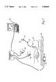
- FIG. 1diagrammatically depicts an arrangement of the invention for use in transesophageal ultrasonic scanning of patient's heart
- FIG. 2is a partially cut away perspective view of an ultrasonic endoscope that is configured in accordance with the invention
- FIG. 3is a perspective view of the ultrasonic probe of an endoscope configured in accordance with this invention and generally illustrates the manner in which the ultrasonic scanning pattern produced by the probe can be positioned in rotation about two orthogonal axes;
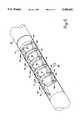
- FIG. 4is a perspective view depicting various portions of the ultrasonic probe of FIG. 3, including a tapered tip, a transducer mounting region that adjoins the tapered tip, and a longitudinally extending probe flexure region that extends from the transducer mounting region;
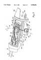
- FIG. 5is an exploded view that depicts structural components that are housed within the transducer mounting region of FIG. 4;
- FIG. 6is a perspective view illustrating the manner in which the probe flexure region of FIG. 4 is structured and arranged;
- FIG. 7is a perspective view of the probe flexure region that illustrates the manner in which flexure is achieved
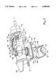
- FIG. 8is a perspective view of a portion of the transducer assembly shown in FIGS. 4 and 5 and depicts the manner in which rotation about one orthogonal axis can be achieved;
- FIG. 9is an exploded view a portion of the transducer assembly of FIGS. 4 and 5 and depicts the manner in which rotation about the second orthogonal axis can be achieved.
- an ultrasonic endoscope 10is inserted into the mouth of a patient 12 and extends downwardly through the patient's throat.
- an ultrasonic probe 14Located at the distal end of ultrasonic endoscope 10 is an ultrasonic probe 14, which is positioned in the patient's esophagus (or stomach) at a position that allows two-dimensional imaging of the patient's heart.
- a phased array or other type of ultrasonic transducerLocated within ultrasonic probe 14 is a phased array or other type of ultrasonic transducer, which can be operated to produce a beam of ultrasonic energy that is swept arcuately to produce a digitally encoded signal that represents an image of the tissue and organs upon which the ultrasonic beam impinges (i.e., in FIG.
- ultrasonic probe 14can be precisely positioned at the most advantageous location of a patient's esophagus (or stomach), which varies from person to person due to the position of the patient's heart and other factors.
- ultrasonic probe 14 of this inventionincludes means for rotating the transducer array (and hence the ultrasonic scanning plane) about two mutually orthogonal axes that extend outwardly from the distal end of ultrasonic endoscope 10.
- This curvature or flexingallows probe 14 to be positioned at a desired location in a patient's esophagus (or stomach) and in firm, but gentle, contact with the esophagus or stomach to thereby maintain ultrasonic probe 14 in an appropriate position throughout a desired scanning interval.
- ultrasonic probe 14also includes an electromagnetic sensor (not specifically indicated in FIG. 1; element 56 in FIGS. 3 and 5).
- the electromagnetic sensoroperates in conjunction with a magnetic field generator 20, an electronics unit 22 and a digital signal processor that is programmed to provide a user interface (indicated in FIG. 1 by personal computer 24).
- the electromagnetic sensor, electronics unit 22 and the interface formed by personal computer 24collectively form what is often called a six-degree-of-freedom measurement or tracking system.
- such a systemprovides a digitally encoded signal representative of both the three-dimensional position of the electromagnetic sensor and the orientation of the sensor.
- magnetic field generator 20is positioned at a known location near patient 12 so that probe 14 (and hence the electromagnetic sensor) is immersed in the magnetic field produced by magnetic field generator 20.
- magnetic field generator 20can be located directly below the patient's torso in a recess 23 in an operating table 25 or other surface that supports patient 12.
- magnetic field generator 20includes a set of transmitter coils (not shown in FIG. 1) that sequentially generates three mutually orthogonal dipole fields, which define the coordinate axes of a fixed three-dimensional reference frame (i.e., the x, y and z axes of a Cartesian coordinate system).
- the electromagnetic sensor of ultrasonic probe 14includes three miniature receiving antennas that allow the electromagnetic sensor to detect magnetic field strength in three orthogonal directions (i.e., detect magnetic field strength relative to a coordinate system that is referenced to the electromagnetic sensor and, hence, ultrasonic probe 14).
- each of the three orthogonal dipole magnetic fields supplied by magnetic field generator 20produces three signals representative of magnetic field strength, a sequence of nine field strength signals is provided during each period of time in which magnetic field generator 20 sequentially generates three orthogonal magnetic dipole fields.
- Each field strength signalincludes magnetic polarity and magnitude information.
- each set of three magnetic field strength signalsis provided relative to a three-dimensional (Cartesian) coordinate system that is established by and associated with the electromagnetic sensor (and hence probe 14)
- the sequence of nine magnetic field strength signalsprovides sufficient information for: (a) determining the location of probe 14 in terms of the three-dimensional coordinate system associated with magnetic field generator 20 (i.e., determining translation of the coordinate system associated with the magnetic sensor in terms of the three-dimensional coordinate system associated with magnetic field generator 20); and, (b) determining the orientation of ultrasonic probe 14 relative to the Cartesian coordinate system associated with magnetic field generator 20 (i.e., determining rotation of the three-dimensional coordinate system associated with the magnetic field sensor (and, hence, ultrasonic probe 14) relative to the coordinate system defined by magnetic field generator 20).
- a sinusoidal excitation signalcan be used to generate the magnetic dipole fields that are provided by magnetic field generator 20
- square wave excitationpreferably is employed.
- excitation of the magnetic field generator with a continuous sine waveresults in magnetic dipole fields that exhibit a corresponding sinusoidal variation with time.
- continuously varying magnetic dipole fieldsinduce eddy currents in electrically conducting structure objects that are subjected to the continuously varying magnetic field.
- the eddy currentsin turn, generate electromagnetic fields that can interfere with the magnetic dipole fields and, hence, cause errors in the position and orientation signals.
- eddy current-induced errorcan be eliminated or greatly reduced by employing square wave excitation signals and by measuring the orthogonal field strength components after any induced eddy currents have subsided (i.e., controlling the time at which the electromagnetic sensor produces the three orthogonal field strength signals relative to the leading and trailing edges of the square wave excitation).
- a six-degree-of-freedom measurement system of the above-described typeis described in further detail in U.S. Pat. Nos. 4,945,305 and 4,849,692, both of which issued to Ernest B. Blood, and are assigned to Ascension Technology Corporation of Buffington, Vt., U.S.A.
- six-degree-of-freedom measurement systemsthat are arranged and function in the above-described manner are manufactured and sold by Ascension Technology Corporation under the trademark "Flock of Birds".
- the Ascension Technology Corporation system used in the currently preferred practice of the inventionincludes a standard range transmitter unit (magnetic field generator 20 in FIG. 1), a microprocessor-based unit identified as "The Bird" (electronics unit 22 in FIG.
- electronics unit 22processes the signals supplied by magnetic field generator 20 and the electromagnetic sensor of probe 14 and provides digitally encoded signals representative of probe position and orientation to personal computer 24 via a conventional RS-232C data bus.
- the electromagnetic sensors that are used in the currently preferred embodiments of the inventionare smaller than sensors conventionally employed in six-degree-of-freedom measuring systems.
- the inventioncurrently employs electromagnetic sensors developed by Ascension Technology Corporation for use in the hereinafter described probe 14 of ultrasonic endoscope 10 (and other applications calling for a miniature sensor).
- the currently preferred electromagnetic sensoris provided with a six-degree-of-freedom measurement system that Ascension Technology Corp. identifies as Model 6D FOB (SBIR-MOD), and is encapsulated to form a 6 mm ⁇ 6 mm ⁇ 9 mm rectangular solid (approximately 0.25 inch ⁇ 0.25 inch ⁇ 0.375 inch).
- the size of the standard or more conventional Ascension Technology Corporation electromagnetic sensoris 25.4 mm ⁇ 25.4 mm ⁇ 20 mm (i.e., one inch ⁇ one inch ⁇ 0.8 inch).
- the six-degree-of-freedom measurement systemallows the invention to provide two-dimensional images that are spatially in registration with one another. That is, the location and orientation of each scanning plane is known with a high degree of precision in terms of the Cartesian coordinate system that is defined by magnetic field generator 20. Precise registration between the two dimensional images allows greatly improved three-dimensional computer-based reconstruction of a scanned heart or other organ.
- three-dimensional cardiac imagingis of growing interest and application relative to hemodynamic monitoring of cardiac function during surgery and postoperative periods as well as for the detection and diagnosis of abnormalities in global or regional myocardial function and cardiac motion.
- the ultrasonic imaging arrangement of FIG. 1provides additional imaging capabilities through the use of a hand-held pointer 28 and a hand-held ultrasonic probe 30.
- Hand-held pointer 28includes an electromagnetic sensor of the type described relative to ultrasonic probe 14 of endoscope 10. As is indicated in FIG. 1, hand-held pointer 28 is connected to electronics unit 22 so as to provide personal computer 24 with signals representative of the position and orientation of hand-held pointer 28.
- hand-held pointer 28allows three-dimensional identification or "marking" of various anatomical features such as the location of the mid-line of patient 12, various surface contours of the patient's chest, nipples, umbilicus, etc.
- the electromagnetic sensor of hand-held pointer 28is subject to the same electromagnetic fields as the electromagnetic sensor of probe 14 (i.e., receives the dipole magnetic fields provided by magnetic field generator 20), the position and orientation of hand-held pointer 28 is in spatial registration with the ultrasonic images provided by probe 14, thus allowing three-dimensional cardiac imaging in which imaged regions of the heart are shown in proper orientation relative to anatomical reference points.
- Hand-held ultrasonic probe 30 in FIG. 1is of conventional configuration, including a transducer of the linear array, phased array or mechanically scanned variety, which further includes an electromagnetic sensor of the previously described type.
- hand-held ultrasonic probe 30can be used to produce additional two-dimensional images that can be employed with the interlumenally generated images that are provided by probe 14 of ultrasonic endoscope 10.
- Combining the external ultrasonic imaging of hand-held ultrasonic probe 30 with the transesophageal or transgastric ultrasonic imaging provided by ultrasonic endoscope 10 in effectcapitalizes on the respective advantages of internal and external imaging and can result in increased accuracy, image clarity, and more encompassing three-dimensional cardiac images.
- the portion of ultrasonic endoscope 10 that extends through the patient's throat and esophagus and interconnects with ultrasonic probe 14structurally corresponds to conventional endoscopes.
- the currently preferred embodiments of the inventionutilize the control handle and flexible shaft sections (i.e., an endoscope "shell") that is manufactured by ACMI Corporation of Stamford, Conn.
- the handle portion (proximal region) of the depicted ultrasonic endoscope 10is substantially circular in cross section and is tapered to join with a relatively small diameter endoscope shaft 34, which is flexible and extends between handle 32 and ultrasonic probe 14.
- endoscope shaft 34preferably exhibits a relatively high degree of torsional rigidity (i.e., rotation of handle 32 causes a substantially identical amount of rotation of the end of endoscope shaft 34 that is joined to ultrasonic probe 14).
- ultrasonic probe 14is also structured for torsional rigidity, thereby allowing probe 14 to be positioned at a desired location in a patient's esophagus or stomach (e.g., behind the left atrium or left ventricle).
- ultrasonic probe 14includes the previously mentioned proximal flexible region, thereby allowing probe 14 to be positioned in firm contact with the wall of the patient's esophagus or stomach.
- control knob 19 for controlling flexure of ultrasonic probe 14is mounted concentrically with control knob 16 (which, as previously mentioned, controls rotation of the scanning pattern produced by probe 14 about one of two orthogonal axes).
- control knob 16which, as previously mentioned, controls rotation of the scanning pattern produced by probe 14 about one of two orthogonal axes.
- a drive pulley 36mounted to the interior end of the shaft on which control knob 19 is mounted.
- a similarly sized drive pulley 38mounted to the interior end of the shaft of control knob 16 .
- Encircling drive pulleys 36 and 38are small diameter wires (or, alternatively, inelastic strings or cables) 40 and 42, respectively, which pass along the interior of handle 32 and through the central portion of endoscope shaft 34. As shall be described relative to FIGS.
- wire 40controls flexure of the proximal region of ultrasonic probe 14.
- wire 42controls rotation of the probe 14 scanning plane about an axis that is substantially perpendicular to the longitudinal centerline of endoscope shaft 34 (and hence the longitudinal axis of probe 14).
- control knob 18which controls rotation of the ultrasonic scanning plane produced by ultrasonic probe 14 about a second orthogonal axis extends outwardly from the rear portion of handle 32.
- a 90 degree drive unit(not shown in FIG. 2), which couples control knob 18 to a small diameter flexible shaft 44.
- the drive unitis a 1:5 speed reducer sold by Stock Drive Products of New Hyde Park, N.Y. and identified by part number A2Z23-25R0508.
- flexible shaft 44which is driven by the drive unit, extends longitudinally through the central opening of handle 32 and endoscope shaft 34 passing coaxially through a flexible tube 46. As shall be described relative to FIG.
- control knob 18rotates the ultrasonic transducers of ultrasonic probe 14 in a manner that tilts the ultrasonic scanning pattern toward or away from the distal end of ultrasonic probe 14, i.e., "rocks" the ultrasonic scanning pattern about an axis that is orthogonal to the longitudinal axis of ultrasonic probe 14.
- Electrical cable assembly 48extends outwardly through handle 32 and includes microcoaxial cables and conventional wires necessary for transmitting electrical signals to and from ultrasonic probe 14.
- electrical cable assembly 48includes conductors which carry the position and orientation signals provided by the electromagnetic sensor of ultrasonic probe 14. As is indicated in FIG. 1, the conductors carrying the position and orientation signals are routed to electronics unit 22. It will be recognized by those skilled in the art that the microcoaxial cables and other conductors that transmit signals to and from ultrasonic probe 14 for purposes of obtaining ultrasonic images are directed to conventional arrangements (not shown in FIG. 1) for producing excitation signals for probe 14 and analyzing and/or storing signals representative of the ultrasonic images obtained.
- FIG. 3generally depicts the exterior features of ultrasonic probe 14 and, in addition, illustrates rotation of the probe scanning pattern about two orthogonal axes 66 and 70, both of which extend orthogonally from longitudinal centerline 62 of probe 14.
- the exterior of the configuration of ultrasonic probe 14is established by a tapered tip 50 that gradually increases in circular cross section and is smoothly joined with an elastomeric sheath 52.
- Elastomeric sheath 52is transparent to acoustic energy and surrounds an assembly 53 that includes the ultrasonic transducer array, an arrangement by which the invention rotates the probe scanning pattern about orthogonal axes 66 and 70.
- Extending rearwardly from acoustically transparent elastomeric sheath 52is a probe flexure region 54 which joins ultrasonic probe 14 with endoscope shaft 34 (shown in FIG. 2).
- ultrasonic probe 14 and endoscope shaft 34are biocompatible for human use and impervious to body fluids.
- tapered tip 50is molded of a relatively pliant elastomeric material such as material identified as product number PMC 724 that is available from Smooth-On Incorporated, Gillette, N.J. If desired or necessary, in order to provide a high degree of resistance to infusion of body fluids and/or superior sterilization capability, a suitable conformal coating can be applied to the outer surface of tapered tip 50. In any case, in the currently preferred embodiments, tapered tip 50 encapsulates an electromagnetic sensor 56 of the type described relative to FIG.
- a microphone 58which serves as a phonocardiogram pick up also is encapsulated in tapered tip 50 being located adjacent forward face of electromagnetic sensor 56.
- Microphone 58supplies electrical signals representative of heart sounds thereby allowing a determination of cardiac timing (i.e., temporal identification of events in the cardiac cycle) in accordance with known techniques such as those disclosed in U.S. Pat. No. 4,546,777, which issued to Groch et al.
- the derived timing signalscan be used to gate (trigger) the ultrasonic transducer array so that two-dimensional image information is produced at predetermined points during the cardiac cycle.
- the cardiac timing signalscan be used to provide temporal registration between each two-dimensional image that is generated by ultrasonic probe 14 and the cardiac cycle.
- the signals provided by microphone 58 of ultrasonic probe 14can be processed by either of the two above-mentioned techniques to provide a set of two-dimensional images of the left ventricle under end diastolic and end systolic conditions.
- End diastolic and end systolic left ventricle volumescan then be estimated by processing the two-dimensional images to obtain three-dimensional end diastolic and end systolic images.
- the end diastolic and end systolic left ventricle volumesreadily yield a measure of stroke volume and ejection fraction, which are useful in diagnosing the location, extent and degree of leftventricular dyssynergy.
- cross-sectional geometry of elastomeric sheath 52exceeds that of both the adjoining portion of tapered tip 50 and the adjoining terminus of probe flexure region 54. More specifically, in the arrangement shown in FIG. 3, the central region of elastomeric sheath 52 is of generally rectangular cross-sectional geometry, with the corner regions being smoothly radiused to facilitate passage of ultrasonic probe 14 along the curved pathway formed by a patient's throat and esophagus. Extending between the central region of elastomeric sheath 52 and its interface with tapered tip 50 is a region that is contoured to form a smooth and gradual transition with tapered tip 50. Similarly, a smoothly contoured transition is formed between the mid-section of acoustically transparent sheath 52 and the outer surface of probe flexure region 54.
- the two-dimensional scanning pattern produced by ultrasonic probe 14can be rotated about two orthogonal axes so that ultrasonic endoscope 10 provides multi-planar imaging signals. More specifically, illustrated in FIG. 3 is a fan-shape ultrasonic scanning pattern 60, which is shown in a reference position in which the two-dimensional scanning pattern lies in a plane that is defined by coordinate axes 66 and 70 and is substantially perpendicular to the longitudinal axis 62 of ultrasonic probe 14. In practice, when ultrasonic probe 14 is positioned as shown in the arrangement of FIG.
- control knobs 16 and 18are operated to position ultrasonic scanning pattern 60 in the depicted reference position, a two-dimensional substantially transverse cardiac image can be produced.
- control knob 16is operated to rotate ultrasonic scanning pattern 60 about axis 66 (indicated by arrows 64 in FIG. 3)
- ultrasonic scanning pattern 60is rotated to be in closer alignment with the long axis of a patient's heart.
- control knob 18 of FIGS. 1 and 2is operated to rotate ultrasonic scanning pattern 60 about axis 70 (indicated by arrows 68 in FIG. 3)
- scanning pattern 60is tilted toward (or away from) the distal end of ultrasonic probe 14, i.e., the rounded end of tapered tip 50.
- rotation of ultrasonic scanning pattern 60 about scanning axis 70allows positioning of ultrasonic scanning pattern 60 to obtain multiple transverse images of a patient's heart.
- ultrasonic probe 14is configured for 90 degrees of scanning plane rotation about each of the scanning plane axes 66 and 70 ( ⁇ 45°, relative to the reference position shown in FIG. 3). Although greater rotational capability can be provided, ⁇ 45° of rotation and tilt (or translation) provides multi-planar scanning capability that is sufficient for full and complete imaging of a patient's heart.
- probe flexure region 54includes a plurality of flexure links 72 that are pivotably interconnected with one another and extend between first and second coupling rings 74 and 76.
- each flexure link 72includes an annular section 78 and arms 80 that extend orthogonally away from diametrically opposed locations along the cylindrical face of annular section 78.
- arms 80are substantially parallel to one another over the major portion of their length and, in addition, extend in parallel relationship with the longitudinal axis 62 of ultrasonic probe 14. As is shown in both FIGS.
- each arm 80includes a region 82 that is located adjacent to and extends angularly away from annular sections 78 to thereby allow annular section 78 of an adjoining flexure link 72 to be positioned between the outer ends of a pair of arms 80.
- annular section 78 of each flexure link 72includes a pair of openings 84 that are positioned for alignment with openings 86 in arms 80 when flexure links 72 are assembled with one another.
- Pins 88pass freely through openings 86 in arms 80 and are press-fit or otherwise retained in the openings 84 of flexure link annular section 78 to thereby interconnect adjacent flexure links 72 in a manner that allows pivotable movement.
- first coupling ring 74is pivotably interconnected with the distal-most flexure ring 72 and joins probe flexure region 54 with the portion of ultrasonic probe 14 that houses the probe ultrasonic transducer array and the mechanism (53 in FIG. 3) that provides the previously discussed rotation of the ultrasonic scanning pattern 60 about the two orthogonal axes 66 and 70.
- the portion of ultrasonic probe 14 that houses the transducer assembly(generally indicated in FIGS. 4 and 5 by reference numeral 92), includes an axially cylindrical collar 94 extending toward probe flexure region 54 and coaxially surrounding longitudinal axis 62 of ultrasonic probe 14. As is best shown in FIG.
- cylindrical collar 94is configured and dimensioned for installation in a cylindrical recess 96, which is formed at one end of first coupling ring 74. Extending axially from the second end of first coupling ring 74 and concentric with recess 96 is a cylindrical collar 98, the outer diameter of which is substantially identical to the outer diameter of the flexure link annular sections 78. Located in cylindrical collar 98 of first coupling ring 74 is a pair of diametrically opposed circular openings 100, which correspond in size to openings 84 in flexure links 72. As can be seen in both FIGS.
- first coupling ring 74allows first coupling ring 74 to be pivotably interconnected with the distal-most flexure link 72 of probe flexure region 54 in the same manner as adjacent flexure links 72 are pivotably interconnected with one another. That is, openings 86 in the diametrically opposed arms 80 of the distal-most flexure links 72 are aligned with openings 100 in collar 98 and pins (88 in FIG. 6) are securely installed in openings 100 of first coupling ring 74.
- Second coupling ring 76joins probe flexure region 54 to the distal end of endoscope shaft 34, which is shown in FIG. 2.
- second coupling ring 76includes an axially extending cylindrical recess that is dimensioned for receiving endoscope shaft 34.
- Circular openings 102which are circumferentially spaced apart from one another in the wall region of the cylindrical recess permit second coupling ring 76 (and hence ultrasonic probe 14) to be securely joined with endoscope shaft 34 with screws or other fasteners.
- Pivot arms 106which are configured and dimensioned to correspond to arms 80 of the flexure links 72 extend outwardly from annular flange 104 of second coupling ring 76. As is shown in FIG. 4, pivot arms 106 are pivotably connected with annular section 78 of the proximal-most flexure link 72 (i.e., the flexure link 72 that is located nearest the terminus of probe flexure region 54).
- annular flange 104 of second coupling ring 76 and annular section 78 of each flexure ring 72includes a pair of diametrically opposed openings 108, with each opening 108 being positioned midway between the probe flexure region pivot arms (i.e., arms 80 of flexure links 72 and arms 106 of second coupling ring 76).
- openings 108lie in a common plane when probe flexure region 54 is structured and assembled in the above described manner. As is shown in FIG.
- openings 108in effect form two spaced apart guides for pull wires 110 which pass through the interior of endoscope shaft 34 from handle 32 of ultrasonic endoscope 10 and are securely attached to first coupling ring 74.
- pull wires 110correspond to wire 40, which encircles pulley 38 in the endoscope control handle.
- rotating control knob 19will place one of the pull wires 110 in FIG. 7 under tension, while releasing tension in the other pull wire 110.
- probe flexure region 54provides at least two important operational features.
- controlled flexureis provided in a plane that is defined by openings 108 of flexure links 72 of probe 14 (FIGS. 6 and 7)
- torsional forces caused by rotation of endoscope 10are transferred between endoscope shaft 34 and first coupling ring 74 (and, hence, the ultrasonic scanning array) without slippage.
- This torsional rigidityallows precise positioning of the ultrasonic scanning pattern 60 produced by ultrasonic probe 14 with respect to rotation within a patient's esophagus (or stomach). That is, the centerline of the two-dimensional scanning pattern produced by probe 14 can be precisely positioned relative to the long axis of a patient's heart.
- the second important operational and functional aspect of the above-described probe flexure region 54is the ability to in effect tilt ultrasonic probe 14 to thereby ensure gentle but firm contact between the portion of ultrasonic probe 14 that emits ultrasonic energy and a patient's esophagus.
- Firm but gentle contactis important from the standpoint of positioning and maintaining ultrasonic probe 14 in a desired position throughout a desired interval of ultrasonic scanning.
- Urging probe 14 into contact with the esophagusalso is advantageous from the standpoint of obtaining high quality images since a uniform probe/esophagus interface normally is established.
- the transducer assembly of ultrasonic probe 14(which is generally indicated in FIG. 3 by reference numeral 53) includes: an ultrasonic transducer array 120; an array holder 122 to which ultrasonic array 120 mounts; a gimbal mount 124, which is configured for rotation of array holder 122 (and hence ultrasonic transducer array 120) about coordinate axis 70 in FIG.
- gimbal mount 124includes a downwardly extending cylindrical shaft 128 which passes through a circular opening in a baseplate 130 of housing unit 126.
- shaft 128is rotated in the hereinafter described manner, ultrasonic transducer array 120 (and, thus, the associated ultrasonic scanning pattern 60 in FIG. 3) is rotated about the previously described coordinate axis 66 (shown in FIGS. 3, 4, and 9).
- Ultrasonic transducer array 120 of the currently preferred embodiment of the inventionis a 48 element, 4.8 megahertz type TE transducer unit, which is manufactured by Echo Ultrasound of Reedsville, Pa., U.S.A.
- the currently preferred ultrasonic transducer array 120includes a substantially rectangular upper plate 132 which contains the individual transducers of the array, and two parallel, spaced-apart downwardly extending rectangular flanges 134.
- the upper surface of the depicted array holder 122is configured to form a rectangular frame that is sized for receiving the downwardly extending flanges 134 of ultrasonic transducer array 120. More specifically, array holder 122 includes two parallel spaced-apart strips 136 that extend between corner regions of two downwardly extending side panels 138 that are substantially triangular in geometry. Extending outwardly from the side panels 138 of array holder 122 are circular pivot shafts 139 that allow rotation of array holder 122 (and hence ultrasonic transducer array 120 about an axis that is parallel to upper plate 132 (and coordinate axis 70 of FIGS. 3, 4 and 8).
- pivot shafts 139 of array holder 122extend through circular openings 140 in upwardly extending parallel walls 142 of gimbal mount 124 to allow rotation in the manner described above (i.e., rotation of transducer array 120 about coordinate axis 70 of ultrasonic probe 14).
- cylindrical shaft 128passes through baseplate 130 of housing unit 126 to thereby allow rotation of ultrasonic transducer array 120 about coordinate axis 66 in FIGS. 3, 4, and 9.
- cylindrical shaft 128passes through a circular opening 144 that is located in the central region of a seal 146.
- seal 146is installed in a recess 148 of geometry substantially identical to the geometry of seal 146.
- Tabular regions 150 that are formed in seal 128 and extend away from seal opening 144prevent seal 146 from rotation in recess 148, and, thus, prevent rotation of seal 148 with rotation of gimbal mount 124 (and hence ultrasonic transducer array 120).
- Seal 146prevents acoustic coupling fluid or gel (not specifically shown in the figures) from passing through baseplate 130 of housing unit 126. More specifically, in the depicted arrangement, housing unit 126 in effect partitions the transducer region of ultrasonic probe 16 into upper and lower compartment-like regions. As can be ascertained from FIG.
- the upper regionis defined by housing unit baseplate 130, parallel walls 152 that extend orthogonally upward from baseplate 130, and elastomeric sheath 52, which forms the outer surface of the mid-section (transducer array region) of ultrasonic probe 14.
- elastomeric sheath 52Extending about the edge of each housing unit wall 152 is a groove 154 which receives a corresponding edge region of elastomeric sheath 52.
- these edge regions of elastomeric sheath 52are formed with peripherally extending beads that project into grooves 154.
- grooves 154allow a fluid-tight juncture to be formed between housing unit 126 and elastomeric sheath 52 through use of an adhesive and/or a tension band (e.g., string, wire, etc.) that forms elastomeric sheath 52 into grooves 154.
- a tension bande.g., string, wire, etc.
- acoustic coupling fluid or gelfills the compartment-like region defined between the upper surface of housing unit baseplate 130 and elastomeric sheath 52.
- the currently preferred embodiments of the inventioninclude an elastomeric bellows 158.
- bellows 158includes downwardly extending side panels that are configured to snugly encompass the base region of gimbal mount 124.
- One or more grooves 160 that extend around the base region of gimbal mount 124are provided for forming a fluid-tight seal between the downwardly extending walls of bellows 158 and the exterior portion of gimbal mount 124 that is contacted by bellows 158.
- the interior surface of the downwardly extending bellows walls 158includes a bead (not shown in FIG. 5) which is received by grooves 160.
- bellows 158can be joined to gimbal mount 124 in the same manner as elastomeric sheath 52 is jointed to gimbal mount 124 (e.g., by means of an adhesive sealant and/or by banding the installed bellows 158 so that the elastomeric material forming downwardly extending side panels of bellows 158 is forced into groove 160).
- a rectangular opening 164is formed in the upper portion of elastomeric bellows 158.
- bellows 158When bellows 158 is secured to gimbal mount 124, the edges of array holder 122 are bonded to adjacent portions of bellows 158 by means of a suitable adhesive or other appropriate technique.
- Ultrasonic transducer array 120is then installed within rectangular opening 164.
- the upper portion of elastomeric bellows 158includes a series of fan-like folds 166 that extend peripherally around bellows 158. Fan-like folds 166 are sufficient in number and configuration to allow the previously discussed rotation of ultrasonic transducer array 120 about the orthogonal axes 66 and 70 (shown in FIGS.
- Both bellows 158 and elastomeric sheath 52 of the currently preferred embodimentsare formed by dipping or otherwise coating suitably shaped molds with a thin layer of uncured synthetic material.
- Tactylon 453(15% solids) and supplied by Tactylon Technologies of Vista, Calif. has been used to form bellows and sheath wall thicknesses on the order of 0.005 inch.
- the compartment-like region that is formed on the opposite side of baseplate 130 of housing unit 126extends from the distal-most wall 152 of housing unit 126 to the portion of housing unit 126 that forms collar 94.
- collar 94mates with and is fastened to first coupling ring 74 to thereby join probe flexure region 54 to the remaining structure of ultrasonic probe 14.
- the lower boundary of the compartment-like regionis formed by a longitudinally extending cover plate 170 that is of arcuate cross-sectional geometry. As is indicated in FIGS. 4 and 5, cover plate 170 mates with and is fastened to the lower portion of housing unit 126.
- cylindrical shaft 128 of gimbal mount 124extends through baseplate 130 of housing unit 126 (i.e., through seal 146 in FIG. 5). Extending circumferentially about the outer wall of cylindrical shaft 128 are two spaced-apart grooves 174 and 176 (shown most clearly in FIG. 9). As is indicated in FIG. 8, a compression type retainer ring 170 is installed in groove 174 to maintain cylindrical shaft 128 (and hence gimbal 124) assembled with housing unit 126. As also is shown in FIG. 8, wire 42, which is driven by endoscope control knob 16 of FIG. 2, is installed in groove 174 of cylindrical shaft 128.
- wire 42(which extends through the central opening of endoscope shaft 34), passes through the central opening of collar 94 of housing unit 126 and is looped about cylindrical shaft 128 of gimbal 124 (i.e., is engaged with groove 176).
- a guide fixture 184Positioned between cylindrical shaft 128 of gimbal 124 and collar 94 of housing unit 126 is a guide fixture 184 that is formed in or secured to baseplate 130 of housing unit 126.
- guide fixture 184Included in guide fixture 184 are two substantially parallel elongate upwardly extending projections 186.
- Elongate projections 186 of guide fixture 184serve as guides for wire 42, with wire 42 passing through circular openings that extend longitudinally through projections 186.
- gimbal 124, array holder 122 and ultrasonic transducer array 120can be rotated about axis 66 by moving wire 42 to cause rotation of cylindrical shaft 128.
- endoscope 10that is depicted in FIG. 2
- the necessary movement of wire 42can be obtained by rotating control knob 16 which is linked to and rotates pulley 38.
- various other "pull-string" arrangementscan be employed to cause rotation of cylindrical shaft 128 to thereby rotate ultrasonic transducer array (and the ultrasonic scanning pattern produced by the array) about axis 66 in FIG. 8.
- the electromagnetic sensor of ultrasonic probe 14operates in conjunction with a magnetic field generator 20 to provide signals representative of the position and orientation of the electromagnetic sensor relative to a three-dimensional coordinate system that is established by (referenced to) the magnetic field generator.
- electromagnetic sensor 56provides signals representative of the position and orientation of ultrasonic probe 14 with respect to the three-dimensional coordinate system established by the magnetic field generator.
- the position and orientation of the ultrasonic scanning pattern60 in FIG. 3).
- the ultrasonic scanning pattern 60(in FIG. 3) is rotatable about two orthogonal axes 66 and 70 (in FIGS. 3, 4, 8 and 9).
- the position(s) of axes 66 and 70are fixed in space relative to the position of electromagnetic sensor 56.
- the origin of the two-dimensional coordinate system defined by axes 66 and 68can be determined relative to the three-dimensional space defined by magnetic field generator 20 of FIG. 1 by conventional coordinate translation techniques.
- the orientation of ultrasonic scanning pattern 60 in the three-dimensional coordinate system defined by magnetic field generator 20can then be determined based on the amount ultrasonic scanning pattern 60 is rotated about axes 66 and 70 (i.e., by the amount that control wire 42 rotates gimbal mount 124 (shown in FIG. 8) and by the amount ultrasonic transducer array 120 is tilted toward or away from longitudinal axis 62 of ultrasonic probe 14 (shown in FIG. 4)).
- potentiometer 190an indication of the rotational position of gimbal mount 124 relative to axis 66 (and hence the rotation of ultrasonic scanning pattern 60 about axis 66) is provided by a potentiometer, which is identified in FIG. 8 by reference numeral 190.
- potentiometer 190 of the currently preferred embodimentsis a commercially available component that is sold by Mouser Electronics of Gilroy, Calif. and is identified by part number 31VC401.
- potentiometer 190is of planar geometry and is mounted to plate 130 of housing unit 126.
- a wiper track 192extends across the surface of potentiometer 190 in spaced apart parallel relationship with the outer circumference of cylindrical shaft 128.
- a guide ring 194is press fit or otherwise retained within the terminal region of the central opening of cylindrical shaft 128.
- Guide ring 194includes an actuator arm 196, which extends outwardly through a recess of cylindrical shaft 128 and which pivotably interconnects with the wiper arm of potentiometer 190.
- FIG. 9is shown in exploded view to better illustrate important aspects of the arrangement.
- a pair of pull strings 200 and 202are connected to diagonally opposite corners of array holder 122, with pull strings 200 and 202 extending through the central opening of gimbal mount cylindrical shaft 128.
- pull strings 200 and 202pass through a tubular centering guide 204 that is formed in the central opening of guide ring 194 (which was described relative to FIG.
- pull strings 200 and 202Passing from centering guide 204 of guide ring 194, pull strings 200 and 202 are routed through channel-like recesses in wedge-like projection 206 that forms an upwardly extending inclined surface along the mid-region of guide fixture 184 (described earlier relative to FIG. 8). At the lower terminus of wedge-like projection 206, pull strings 200 and 202 pass downwardly through openings 208 in guide fixture 184. As can be seen in FIG. 9, passage of pull strings 200 and 202 through openings 208 places the pull strings in a recess 210 of housing unit 126, with the recess 210 being spaced apart from cylindrical collar 94.
- a rotatable shaft 212Extending axially along recess 210 is a rotatable shaft 212, which passes through a bearing 213 and includes a pair of spaced apart circumferential grooves.
- Pull strings 200 and 202are wound in the grooves of rotatable shaft 212, with one of the pull strings being wound in a clockwise direction and the other pull string being wound in a counter dockwise direction.
- one of the pull strings 200 and 202will unwind from shaft 212 and the other pull string will be wound onto shaft 212.
- array holder 122will tilt toward or away from ultrasonic probe longitudinal axis 62. That is, array holder and, hence, ultrasonic scanning pattern 160 of FIG. 3 will rotate about coordinate axis 70 of FIGS. 3, 4, 8 and 9.
- shaft 212is coupled to and driven by flexible shaft 44 of endoscope 10 (both described relative to FIGS. 1 and 2).
- FIG. 8illustrates a suitably configured and mounted potentiometer 216, which is of rectangular geometry and is mounted in a recess in the central portion of one of the pivot shafts 139 that extend outwardly from array holder 122 to pivotally interconnect array holder 122 with gimbal mount 124.
- the wiper arm of potentiometer 216is secured to gimbal mount 24 so that the wiper arm of the potentiometer moves along a wiper track when array holder 122 tilts, thereby providing a resistance value indicative of the rotational position of array holder 122 relative to gimbal mount 124 and hence, the rotational position of ultrasonic scanning pattern 60 relative to axis 66 (FIG. 3).
- One commercially available potentiometer suitable for use as potentiometer 216is available from Rohm Corporation of Irvine, Calif. and is identified by part number MVR 32.
- tapered tip 50 of ultrasonic probe 14is molded of an elastomeric material and encapsulates electromagnetic sensor 56.
- the currently preferred embodiments of the inventioninclude provision for mounting of electromagnetic sensor 56 and secure retainment of tapered tip 50.
- a shelf-like projection 220for supporting electromagnetic sensor 56.
- a circular post 222which includes a series of circumferentially extending rings or ridges.
- a mold cavity that corresponds to the desired configuration of tapered tip 50is filled with uncured elastomeric material and the partially assembled housing unit is placed over the mold cavity with microphone 58, electromagnetic sensor 56 and post 222 extending downwardly into the cavity.
- the elastomeric materialhas cured to form tapered tip 50
- the partially assembled housing unit 26 and securely attached tapered tip 50are withdrawn from the mold.
- ultrasonic probe 14In view of the foregoing description of the currently preferred embodiments of ultrasonic probe 14, it will be recognized that the number of electrical conductors that must be routed through the probe is relatively high in view of the small cross-sectional size of ultrasonic probe 14.
- the previously described embodiment of the inventionemploys an ultrasonic transducer array (120 in FIG. 5) that includes 48 transducer elements and requires on the order of 65 electrical connections and, hence, electrical conductors.
- the currently preferred embodiments of the inventionemploy miniature ribbon-like dynamic flex circuits in which rolled annealed copper conductors that are 2/1000 inch thick and 5/1000 inch wide are spaced apart from one another by 5/1000 inch and bonded between two layers of 1/1000 inch thick polyimide film.
- This arrangementis illustrated in FIG. 8 with the ribbon-like flex circuits being identified by reference numeral 224.
- Interconnection of the individual conductors of the flex circuits 224 with the previously mentioned microcoaxial cables and other conductors that extend through endoscope shaft 34preferably is made in the interior region of cylindrical collar 94 of housing unit 126.
Landscapes
- Health & Medical Sciences (AREA)
- Life Sciences & Earth Sciences (AREA)
- Engineering & Computer Science (AREA)
- Biophysics (AREA)
- Physics & Mathematics (AREA)
- Surgery (AREA)
- General Health & Medical Sciences (AREA)
- Molecular Biology (AREA)
- Veterinary Medicine (AREA)
- Public Health (AREA)
- Pathology (AREA)
- Biomedical Technology (AREA)
- Heart & Thoracic Surgery (AREA)
- Medical Informatics (AREA)
- Animal Behavior & Ethology (AREA)
- Radiology & Medical Imaging (AREA)
- Nuclear Medicine, Radiotherapy & Molecular Imaging (AREA)
- Human Computer Interaction (AREA)
- Nanotechnology (AREA)
- Chemical & Material Sciences (AREA)
- Computer Networks & Wireless Communication (AREA)
- Radar, Positioning & Navigation (AREA)
- Remote Sensing (AREA)
- Gynecology & Obstetrics (AREA)
- General Physics & Mathematics (AREA)
- Optics & Photonics (AREA)
- Crystallography & Structural Chemistry (AREA)
- Physiology (AREA)
- Ultra Sonic Daignosis Equipment (AREA)
Abstract
Description
Claims (21)
Priority Applications (3)
| Application Number | Priority Date | Filing Date | Title |
|---|---|---|---|
| US08/116,293US5398691A (en) | 1993-09-03 | 1993-09-03 | Method and apparatus for three-dimensional translumenal ultrasonic imaging |
| PCT/US1994/009875WO1995006436A1 (en) | 1993-09-03 | 1994-09-01 | Three-dimensional translumenal ultrasonic imaging |
| AU76798/94AAU7679894A (en) | 1993-09-03 | 1994-09-01 | Three-dimensional translumenal ultrasonic imaging |
Applications Claiming Priority (1)
| Application Number | Priority Date | Filing Date | Title |
|---|---|---|---|
| US08/116,293US5398691A (en) | 1993-09-03 | 1993-09-03 | Method and apparatus for three-dimensional translumenal ultrasonic imaging |
Publications (1)
| Publication Number | Publication Date |
|---|---|
| US5398691Atrue US5398691A (en) | 1995-03-21 |
Family
ID=22366314
Family Applications (1)
| Application Number | Title | Priority Date | Filing Date |
|---|---|---|---|
| US08/116,293Expired - LifetimeUS5398691A (en) | 1993-09-03 | 1993-09-03 | Method and apparatus for three-dimensional translumenal ultrasonic imaging |
Country Status (3)
| Country | Link |
|---|---|
| US (1) | US5398691A (en) |
| AU (1) | AU7679894A (en) |
| WO (1) | WO1995006436A1 (en) |
Cited By (209)
| Publication number | Priority date | Publication date | Assignee | Title |
|---|---|---|---|---|
| US5529070A (en)* | 1990-11-22 | 1996-06-25 | Advanced Technology Laboratories, Inc. | Acquisition and display of ultrasonic images from sequentially oriented image planes |
| DE19608971A1 (en)* | 1995-04-03 | 1996-10-10 | Hans Dr Polz | Method and device for recording diagnostically usable, three-dimensional ultrasound image data sets |
| US5575288A (en)* | 1993-05-28 | 1996-11-19 | Acuson Corporation | Compact rotationally steerable ultrasound transducer |
| US5647367A (en)* | 1996-05-31 | 1997-07-15 | Hewlett-Packard Company | Scanning ultrasonic probe with locally-driven sweeping ultrasonic source |
| US5701898A (en)* | 1994-09-02 | 1997-12-30 | The United States Of America As Represented By The Department Of Health And Human Services | Method and system for Doppler ultrasound measurement of blood flow |
| US5724978A (en)* | 1996-09-20 | 1998-03-10 | Cardiovascular Imaging Systems, Inc. | Enhanced accuracy of three-dimensional intraluminal ultrasound (ILUS) image reconstruction |
| WO1998039669A1 (en)* | 1997-03-07 | 1998-09-11 | Sonometrics Corporation | A method for carrying out a medical procedure using a three-dimensional tracking and imaging system |
| WO1998039668A1 (en)* | 1997-03-07 | 1998-09-11 | Sonometrics Corporation | Three-dimensional tracking and imaging system |
| US5830145A (en)* | 1996-09-20 | 1998-11-03 | Cardiovascular Imaging Systems, Inc. | Enhanced accuracy of three-dimensional intraluminal ultrasound (ILUS) image reconstruction |
| US5836882A (en)* | 1997-03-17 | 1998-11-17 | Frazin; Leon J. | Method and apparatus of localizing an insertion end of a probe within a biotic structure |
| US5846198A (en)* | 1996-05-31 | 1998-12-08 | Siemens Aktiengesellschaft | Apparatus for localizing action currents in the heart |
| US5876345A (en)* | 1997-02-27 | 1999-03-02 | Acuson Corporation | Ultrasonic catheter, system and method for two dimensional imaging or three-dimensional reconstruction |
| US5906578A (en)* | 1997-06-18 | 1999-05-25 | Rajan; Govinda N. | Method and system for probe positioning in transesophageal echocardiography |
| US5924989A (en)* | 1995-04-03 | 1999-07-20 | Polz; Hans | Method and device for capturing diagnostically acceptable three-dimensional ultrasound image data records |
| US5924991A (en)* | 1997-08-22 | 1999-07-20 | Acuson Corporation | Ultrasonic system and method for harmonic imaging in three dimensions |
| US5938615A (en)* | 1993-02-01 | 1999-08-17 | Endosonics Corporation | Ultrasound catheter probe |
| WO1999055244A1 (en)* | 1998-04-28 | 1999-11-04 | Goldberg Nahum S | Method and system for trans-lumenal radio-frequency ablation through an endoscope |
| US5983126A (en)* | 1995-11-22 | 1999-11-09 | Medtronic, Inc. | Catheter location system and method |
| US6014473A (en)* | 1996-02-29 | 2000-01-11 | Acuson Corporation | Multiple ultrasound image registration system, method and transducer |
| US6027451A (en)* | 1997-09-26 | 2000-02-22 | Ep Technologies, Inc. | Method and apparatus for fixing the anatomical orientation of a displayed ultrasound generated image |
| US6045508A (en)* | 1997-02-27 | 2000-04-04 | Acuson Corporation | Ultrasonic probe, system and method for two-dimensional imaging or three-dimensional reconstruction |
| US6120453A (en)* | 1997-11-17 | 2000-09-19 | Sharp; William A. | Three-dimensional ultrasound system based on the coordination of multiple ultrasonic transducers |
| US6122967A (en)* | 1998-06-18 | 2000-09-26 | The United States Of America As Represented By The United States Department Of Energy | Free motion scanning system |
| US6228028B1 (en) | 1996-11-07 | 2001-05-08 | Tomtec Imaging Systems Gmbh | Method and apparatus for ultrasound image reconstruction |
| US6234968B1 (en) | 1999-06-15 | 2001-05-22 | Acuson Corporation | 3-D diagnostic medical ultrasound imaging using a 1-D array |
| US6246898B1 (en) | 1995-03-28 | 2001-06-12 | Sonometrics Corporation | Method for carrying out a medical procedure using a three-dimensional tracking and imaging system |
| US6248074B1 (en) | 1997-09-30 | 2001-06-19 | Olympus Optical Co., Ltd. | Ultrasonic diagnosis system in which periphery of magnetic sensor included in distal part of ultrasonic endoscope is made of non-conductive material |
| US6315724B1 (en) | 1999-10-19 | 2001-11-13 | Biomedicom Ltd | 3-dimensional ultrasonic imaging |
| US20020026118A1 (en)* | 2000-08-18 | 2002-02-28 | Assaf Govari | Three-dimensional reconstruction using ultrasound |
| US20020049375A1 (en)* | 1999-05-18 | 2002-04-25 | Mediguide Ltd. | Method and apparatus for real time quantitative three-dimensional image reconstruction of a moving organ and intra-body navigation |
| EP1240869A3 (en)* | 2001-03-16 | 2002-11-27 | GE Medical Systems Global Technology Company LLC | Transesophageal ultrasound probe with imaging element position sensor in scanhead |
| US20030018270A1 (en)* | 2001-05-29 | 2003-01-23 | Makin Inder Raj. S. | Tissue-retaining system for ultrasound medical treatment |
| US6572547B2 (en)* | 2001-07-31 | 2003-06-03 | Koninklijke Philips Electronics N.V. | Transesophageal and transnasal, transesophageal ultrasound imaging systems |
| US20030114749A1 (en)* | 2001-11-26 | 2003-06-19 | Siemens Aktiengesellschaft | Navigation system with respiration or EKG triggering to enhance the navigation precision |
| US20030158477A1 (en)* | 2001-11-09 | 2003-08-21 | Dorin Panescu | Systems and methods for guiding catheters using registered images |
| US6636769B2 (en) | 2000-12-18 | 2003-10-21 | Biosense, Inc. | Telemetric medical system and method |
| US20030199756A1 (en)* | 2002-04-17 | 2003-10-23 | Olympus Optical Co., Ltd. | Ultrasonic diagnostic apparatus and ultrasonic diagnostic method |
| US6638231B2 (en) | 2000-12-18 | 2003-10-28 | Biosense, Inc. | Implantable telemetric medical sensor and method |
| WO2002091906A3 (en)* | 2001-05-14 | 2003-10-30 | U Systems Inc | Method and system for recording probe position during breast ultrasound scan |
| US20030216646A1 (en)* | 2002-03-15 | 2003-11-20 | Angelsen Bjorn A.J. | Multiple scan-plane ultrasound imaging of objects |
| US6652464B2 (en)* | 2000-12-18 | 2003-11-25 | Biosense, Inc. | Intracardiac pressure monitoring method |
| US6658300B2 (en) | 2000-12-18 | 2003-12-02 | Biosense, Inc. | Telemetric reader/charger device for medical sensor |
| US20040011365A1 (en)* | 2002-07-18 | 2004-01-22 | Assaf Govari | Medical sensor having power coil, sensing coil and control chip |
| US6685644B2 (en)* | 2001-04-24 | 2004-02-03 | Kabushiki Kaisha Toshiba | Ultrasound diagnostic apparatus |
| US20040032957A1 (en)* | 2002-08-14 | 2004-02-19 | Mansy Hansen A. | Sensors and sensor assemblies for monitoring biological sounds and electric potentials |
| US20040054288A1 (en)* | 2000-10-18 | 2004-03-18 | Nygaard Per Ehrenreich | Ultrasonic apparatus with rotatable probe, surrounded by a protective resilent sleeve |
| US6719700B1 (en) | 2002-12-13 | 2004-04-13 | Scimed Life Systems, Inc. | Ultrasound ranging for localization of imaging transducer |
| US6722202B1 (en) | 2003-07-16 | 2004-04-20 | The Boeing Company | Method and apparatus for inspecting a structure utilizing magnetically attracted probes |
| US6730313B2 (en) | 2000-01-25 | 2004-05-04 | Edwards Lifesciences Corporation | Delivery systems for periadventitial delivery for treatment of restenosis and anastomotic intimal hyperplasia |
| US6746404B2 (en)* | 2000-12-18 | 2004-06-08 | Biosense, Inc. | Method for anchoring a medical device between tissue |
| US20040122322A1 (en)* | 2002-12-18 | 2004-06-24 | Barbara Ann Karmanos Cancer Institute | Electret acoustic transducer array for computerized ultrasound risk evaluation system |
| US20040138548A1 (en)* | 2003-01-13 | 2004-07-15 | Mediguide Ltd. | Method and system for registering a medical situation associated with a first coordinate system, in second coordinate system using an MPS system |
| US20040152986A1 (en)* | 2003-01-23 | 2004-08-05 | Fidel Howard F. | Ultrasonic imaging device, system and method of use |
| US6773402B2 (en) | 2001-07-10 | 2004-08-10 | Biosense, Inc. | Location sensing with real-time ultrasound imaging |
| US6783499B2 (en) | 2000-12-18 | 2004-08-31 | Biosense, Inc. | Anchoring mechanism for implantable telemetric medical sensor |
| US20040193146A1 (en)* | 2001-02-15 | 2004-09-30 | Endo Via Medical, Inc. | Robotically controlled surgical instruments |
| US20040193042A1 (en)* | 2003-03-27 | 2004-09-30 | Steven Scampini | Guidance of invasive medical devices by high resolution three dimensional ultrasonic imaging |
| US20040237321A1 (en)* | 2003-05-29 | 2004-12-02 | Rudko Robert I. | Replacement heart valve sizing device |
| US20040260322A1 (en)* | 2003-06-20 | 2004-12-23 | Rudko Robert I. | Endovascular tissue removal device |
| EP1185199A4 (en)* | 1999-05-18 | 2005-03-09 | Mediguide Ltd | Medical positioning system |
| US20050222554A1 (en)* | 2004-03-05 | 2005-10-06 | Wallace Daniel T | Robotic catheter system |
| US20050228440A1 (en)* | 1999-05-10 | 2005-10-13 | Endovia Medical Inc. | Surgical instrument |
| US20050261611A1 (en)* | 2004-05-21 | 2005-11-24 | Makin Inder Raj S | Ultrasound medical system and method |
| US20050277853A1 (en)* | 2004-06-14 | 2005-12-15 | Mast T D | System and method for medical treatment using ultrasound |
| US20050283079A1 (en)* | 2004-06-22 | 2005-12-22 | Steen Erik N | Method and apparatus for medical ultrasound navigation user interface |
| US20060057560A1 (en)* | 2004-03-05 | 2006-03-16 | Hansen Medical, Inc. | System and method for denaturing and fixing collagenous tissue |
| US20060058647A1 (en)* | 1999-05-18 | 2006-03-16 | Mediguide Ltd. | Method and system for delivering a medical device to a selected position within a lumen |
| US20060074319A1 (en)* | 2004-09-27 | 2006-04-06 | Siemens Medical Solutions Usa, Inc. | Image plane sensing methods and systems for intra-patient probes |
| US20060173330A1 (en)* | 2004-12-29 | 2006-08-03 | Medison Co., Ltd. | Device for pivoting an ultrasound element assembly of a probe in an ultrasonic diagnosis apparatus |
| US20060253031A1 (en)* | 2005-04-26 | 2006-11-09 | Altmann Andres C | Registration of ultrasound data with pre-acquired image |
| US20070083121A1 (en)* | 2005-09-26 | 2007-04-12 | Hastings Harold M | Transesophageal ultrasound probe with reduced width |
| US20070092123A1 (en)* | 2005-10-18 | 2007-04-26 | Stefan Popescu | Method and device for movement correction when imaging the heart |
| US20070129710A1 (en)* | 2003-07-28 | 2007-06-07 | Rudko Robert I | Endovascular tissue removal device |
| US20070233052A1 (en)* | 1998-02-24 | 2007-10-04 | Hansen Medical, Inc. | Interchangeable surgical instrument |
| US20070239105A1 (en)* | 2001-02-15 | 2007-10-11 | Hansen Medical, Inc. | Coaxial catheter system |
| US20070239120A1 (en)* | 1998-02-24 | 2007-10-11 | Brock David L | Flexible instrument |
| US20070287901A1 (en)* | 1999-05-18 | 2007-12-13 | Mediguide Ltd. | Medical imaging and navigation system |
| US20080009733A1 (en)* | 2006-06-27 | 2008-01-10 | Ep Medsystems, Inc. | Method for Evaluating Regional Ventricular Function and Incoordinate Ventricular Contraction |
| US20080033453A1 (en)* | 1998-02-24 | 2008-02-07 | Hansen Medical, Inc. | Interchangeable surgical instrument |
| US20080086051A1 (en)* | 2006-09-20 | 2008-04-10 | Ethicon Endo-Surgery, Inc. | System, storage medium for a computer program, and method for displaying medical images |
| US20080154123A1 (en)* | 2006-12-21 | 2008-06-26 | Jackson John I | Automated image interpretation with transducer position or orientation sensing for medical ultrasound |
| US20080221434A1 (en)* | 2007-03-09 | 2008-09-11 | Voegele James W | Displaying an internal image of a body lumen of a patient |
| US20080234544A1 (en)* | 2007-03-20 | 2008-09-25 | Ethicon Endo-Sugery, Inc. | Displaying images interior and exterior to a body lumen of a patient |
| US20080319307A1 (en)* | 2007-06-19 | 2008-12-25 | Ethicon Endo-Surgery, Inc. | Method for medical imaging using fluorescent nanoparticles |
| US20090054761A1 (en)* | 2007-08-22 | 2009-02-26 | Ethicon Endo-Surgery, Inc. | Medical system, method, and storage medium concerning a natural orifice transluminal medical procedure |
| US20090076483A1 (en)* | 2007-09-14 | 2009-03-19 | Kenneth Danehorn | Catheter localization system |
| US20090105597A1 (en)* | 2006-10-12 | 2009-04-23 | Innoscion, Llc | Image guided catheter having remotely controlled surfaces-mounted and internal ultrasound transducers |
| US20090182224A1 (en)* | 1999-05-18 | 2009-07-16 | Mediguide Ltd. | Method and apparatus for invasive device tracking using organ timing signal generated from MPS sensors |
| US20090264994A1 (en)* | 1999-06-25 | 2009-10-22 | Hansen Medical, Inc. | Apparatus and methods for treating tissue |
| US7778688B2 (en) | 1999-05-18 | 2010-08-17 | MediGuide, Ltd. | System and method for delivering a stent to a selected position within a lumen |
| US20100256490A1 (en)* | 2004-05-18 | 2010-10-07 | Makin Inder Raj S | Medical system having an ultrasound source and an acoustic coupling medium |
| US7840252B2 (en) | 1999-05-18 | 2010-11-23 | MediGuide, Ltd. | Method and system for determining a three dimensional representation of a tubular organ |
| US7846096B2 (en) | 2001-05-29 | 2010-12-07 | Ethicon Endo-Surgery, Inc. | Method for monitoring of medical treatment using pulse-echo ultrasound |
| US20110054308A1 (en)* | 1999-05-18 | 2011-03-03 | Amit Cohen | Method and system for superimposing virtual anatomical landmarks on an image |
| US20110071395A1 (en)* | 2001-07-31 | 2011-03-24 | Koninklijke Philips Electronics N.V. | Transesophageal and transnasal, transesophageal ultrasound imaging systems |
| US20110118756A1 (en)* | 1998-02-24 | 2011-05-19 | Hansen Medical, Inc. | Interchangeable surgical instrument |
| US20110184684A1 (en)* | 2009-07-21 | 2011-07-28 | Eigen, Inc. | 3-d self-correcting freehand ultrasound tracking system |
| US20110201975A1 (en)* | 2004-05-20 | 2011-08-18 | Makin Inder Raj S | Ultrasound medical system |
| US8007511B2 (en) | 2003-06-06 | 2011-08-30 | Hansen Medical, Inc. | Surgical instrument design |
| US20110213383A1 (en)* | 2002-09-09 | 2011-09-01 | Hansen Medical, Inc. | Surgical instrument coupling mechanism |
| US8081810B2 (en) | 2007-03-22 | 2011-12-20 | Ethicon Endo-Surgery, Inc. | Recognizing a real world fiducial in image data of a patient |
| US20120197112A1 (en)* | 2011-01-30 | 2012-08-02 | Biotex, Inc. | Spatially-localized optical coherence tomography imaging |
| US8311613B2 (en) | 2007-06-20 | 2012-11-13 | Siemens Aktiengesellschaft | Electrode catheter positioning system |
| US8388546B2 (en) | 2006-10-23 | 2013-03-05 | Bard Access Systems, Inc. | Method of locating the tip of a central venous catheter |
| US8388541B2 (en) | 2007-11-26 | 2013-03-05 | C. R. Bard, Inc. | Integrated system for intravascular placement of a catheter |
| US8414505B1 (en) | 2001-02-15 | 2013-04-09 | Hansen Medical, Inc. | Catheter driver system |
| US8437833B2 (en) | 2008-10-07 | 2013-05-07 | Bard Access Systems, Inc. | Percutaneous magnetic gastrostomy |
| US8452068B2 (en) | 2008-06-06 | 2013-05-28 | Covidien Lp | Hybrid registration method |
| US8457718B2 (en) | 2007-03-21 | 2013-06-04 | Ethicon Endo-Surgery, Inc. | Recognizing a real world fiducial in a patient image data |
| US8473032B2 (en) | 2008-06-03 | 2013-06-25 | Superdimension, Ltd. | Feature-based registration method |
| US8478382B2 (en) | 2008-02-11 | 2013-07-02 | C. R. Bard, Inc. | Systems and methods for positioning a catheter |
| US8512256B2 (en) | 2006-10-23 | 2013-08-20 | Bard Access Systems, Inc. | Method of locating the tip of a central venous catheter |
| USD699359S1 (en) | 2011-08-09 | 2014-02-11 | C. R. Bard, Inc. | Ultrasound probe head |
| US20140088404A1 (en)* | 2012-09-27 | 2014-03-27 | Patrick Gross | Patient positioning device, and medical imaging method and apparatus employing same |
| US8781555B2 (en) | 2007-11-26 | 2014-07-15 | C. R. Bard, Inc. | System for placement of a catheter including a signal-generating stylet |
| US8784336B2 (en) | 2005-08-24 | 2014-07-22 | C. R. Bard, Inc. | Stylet apparatuses and methods of manufacture |
| US8801693B2 (en) | 2010-10-29 | 2014-08-12 | C. R. Bard, Inc. | Bioimpedance-assisted placement of a medical device |
| US8849382B2 (en) | 2007-11-26 | 2014-09-30 | C. R. Bard, Inc. | Apparatus and display methods relating to intravascular placement of a catheter |
| USD724745S1 (en) | 2011-08-09 | 2015-03-17 | C. R. Bard, Inc. | Cap for an ultrasound probe |
| US9014851B2 (en) | 2013-03-15 | 2015-04-21 | Hansen Medical, Inc. | Systems and methods for tracking robotically controlled medical instruments |
| US9057600B2 (en) | 2013-03-13 | 2015-06-16 | Hansen Medical, Inc. | Reducing incremental measurement sensor error |
| US9125578B2 (en) | 2009-06-12 | 2015-09-08 | Bard Access Systems, Inc. | Apparatus and method for catheter navigation and tip location |
| US9173713B2 (en) | 2013-03-14 | 2015-11-03 | Hansen Medical, Inc. | Torque-based catheter articulation |
| US9211107B2 (en) | 2011-11-07 | 2015-12-15 | C. R. Bard, Inc. | Ruggedized ultrasound hydrogel insert |
| US9271663B2 (en) | 2013-03-15 | 2016-03-01 | Hansen Medical, Inc. | Flexible instrument localization from both remote and elongation sensors |
| CN105377138A (en)* | 2012-12-26 | 2016-03-02 | 天主关东大学校产学协力团 | Method for producing complex real three-dimensional images, and system for same |
| US9283046B2 (en) | 2013-03-15 | 2016-03-15 | Hansen Medical, Inc. | User interface for active drive apparatus with finite range of motion |
| US9326822B2 (en) | 2013-03-14 | 2016-05-03 | Hansen Medical, Inc. | Active drives for robotic catheter manipulators |
| US9339206B2 (en) | 2009-06-12 | 2016-05-17 | Bard Access Systems, Inc. | Adaptor for endovascular electrocardiography |
| US9358076B2 (en) | 2011-01-20 | 2016-06-07 | Hansen Medical, Inc. | System and method for endoluminal and translumenal therapy |
| US9408669B2 (en) | 2013-03-15 | 2016-08-09 | Hansen Medical, Inc. | Active drive mechanism with finite range of motion |
| US9445734B2 (en) | 2009-06-12 | 2016-09-20 | Bard Access Systems, Inc. | Devices and methods for endovascular electrography |
| US9452018B2 (en) | 2013-03-15 | 2016-09-27 | Hansen Medical, Inc. | Rotational support for an elongate member |
| US9456766B2 (en) | 2007-11-26 | 2016-10-04 | C. R. Bard, Inc. | Apparatus for use with needle insertion guidance system |
| US9457168B2 (en) | 2005-07-01 | 2016-10-04 | Hansen Medical, Inc. | Robotic catheter system and methods |
| US9492097B2 (en) | 2007-11-26 | 2016-11-15 | C. R. Bard, Inc. | Needle length determination and calibration for insertion guidance system |
| US9498601B2 (en) | 2013-03-14 | 2016-11-22 | Hansen Medical, Inc. | Catheter tension sensing |
| US9498291B2 (en) | 2013-03-15 | 2016-11-22 | Hansen Medical, Inc. | Touch-free catheter user interface controller |
| US9521961B2 (en) | 2007-11-26 | 2016-12-20 | C. R. Bard, Inc. | Systems and methods for guiding a medical instrument |
| US9532724B2 (en) | 2009-06-12 | 2017-01-03 | Bard Access Systems, Inc. | Apparatus and method for catheter navigation using endovascular energy mapping |
| US9532840B2 (en) | 2013-03-08 | 2017-01-03 | Hansen Medical, Inc. | Slider control of catheters and wires |
| US9554716B2 (en) | 2007-11-26 | 2017-01-31 | C. R. Bard, Inc. | Insertion guidance system for needles and medical components |
| US9566414B2 (en) | 2013-03-13 | 2017-02-14 | Hansen Medical, Inc. | Integrated catheter and guide wire controller |
| US9575140B2 (en) | 2008-04-03 | 2017-02-21 | Covidien Lp | Magnetic interference detection system and method |
| US9629595B2 (en) | 2013-03-15 | 2017-04-25 | Hansen Medical, Inc. | Systems and methods for localizing, tracking and/or controlling medical instruments |
| US9636031B2 (en) | 2007-11-26 | 2017-05-02 | C.R. Bard, Inc. | Stylets for use with apparatus for intravascular placement of a catheter |
| US9649048B2 (en) | 2007-11-26 | 2017-05-16 | C. R. Bard, Inc. | Systems and methods for breaching a sterile field for intravascular placement of a catheter |
| US9668814B2 (en) | 2013-03-07 | 2017-06-06 | Hansen Medical, Inc. | Infinitely rotatable tool with finite rotating drive shafts |
| US9763641B2 (en) | 2012-08-30 | 2017-09-19 | Delphinus Medical Technologies, Inc. | Method and system for imaging a volume of tissue with tissue boundary detection |
| US9839372B2 (en) | 2014-02-06 | 2017-12-12 | C. R. Bard, Inc. | Systems and methods for guidance and placement of an intravascular device |
| US9901714B2 (en) | 2008-08-22 | 2018-02-27 | C. R. Bard, Inc. | Catheter assembly including ECG sensor and magnetic assemblies |
| US9939911B2 (en) | 2004-01-30 | 2018-04-10 | Electronic Scripting Products, Inc. | Computer interface for remotely controlled objects and wearable articles with absolute pose detection component |
| US10046139B2 (en) | 2010-08-20 | 2018-08-14 | C. R. Bard, Inc. | Reconfirmation of ECG-assisted catheter tip placement |
| US10046140B2 (en) | 2014-04-21 | 2018-08-14 | Hansen Medical, Inc. | Devices, systems, and methods for controlling active drive systems |
| US10074199B2 (en) | 2013-06-27 | 2018-09-11 | Tractus Corporation | Systems and methods for tissue mapping |
| CN108714035A (en)* | 2018-06-26 | 2018-10-30 | 深圳开立生物医疗科技股份有限公司 | A kind of endoscopic ultrasonography and its operating method |
| US10123770B2 (en) | 2013-03-13 | 2018-11-13 | Delphinus Medical Technologies, Inc. | Patient support system |
| US10123843B2 (en) | 2013-03-15 | 2018-11-13 | Auris Health, Inc. | Input device for controlling a catheter |
| US10201324B2 (en) | 2007-05-04 | 2019-02-12 | Delphinus Medical Technologies, Inc. | Patient interface system |
| US10219903B2 (en) | 2008-04-16 | 2019-03-05 | Heart Repair Technologies, Inc. | Transvalvular intraanular band and chordae cutting for ischemic and dilated cardiomyopathy |
| US10238488B2 (en) | 2008-04-16 | 2019-03-26 | Heart Repair Technologies, Inc. | Percutaneous transvalvular intraannular band for mitral valve repair |
| US10285667B2 (en) | 2014-08-05 | 2019-05-14 | Delphinus Medical Technologies, Inc. | Method for generating an enhanced image of a volume of tissue |
| US10349890B2 (en) | 2015-06-26 | 2019-07-16 | C. R. Bard, Inc. | Connector interface for ECG-based catheter positioning system |
| US10363103B2 (en) | 2009-04-29 | 2019-07-30 | Auris Health, Inc. | Flexible and steerable elongate instruments with shape control and support elements |
| US10376672B2 (en) | 2013-03-15 | 2019-08-13 | Auris Health, Inc. | Catheter insertion system and method of fabrication |
| US10418705B2 (en) | 2016-10-28 | 2019-09-17 | Covidien Lp | Electromagnetic navigation antenna assembly and electromagnetic navigation system including the same |
| US10446931B2 (en) | 2016-10-28 | 2019-10-15 | Covidien Lp | Electromagnetic navigation antenna assembly and electromagnetic navigation system including the same |
| US10449330B2 (en) | 2007-11-26 | 2019-10-22 | C. R. Bard, Inc. | Magnetic element-equipped needle assemblies |
| US10456259B2 (en) | 2008-04-16 | 2019-10-29 | Heart Repair Technologies, Inc. | Transvalvular intraannular band for mitral valve repair |
| US10463439B2 (en) | 2016-08-26 | 2019-11-05 | Auris Health, Inc. | Steerable catheter with shaft load distributions |
| US10507009B2 (en) | 2017-10-05 | 2019-12-17 | EchoNous, Inc. | System and method for fusing ultrasound with additional signals |
| US10517505B2 (en) | 2016-10-28 | 2019-12-31 | Covidien Lp | Systems, methods, and computer-readable media for optimizing an electromagnetic navigation system |
| US10524691B2 (en) | 2007-11-26 | 2020-01-07 | C. R. Bard, Inc. | Needle assembly including an aligned magnetic element |
| US10524867B2 (en) | 2013-03-15 | 2020-01-07 | Auris Health, Inc. | Active drive mechanism for simultaneous rotation and translation |
| US10543047B2 (en) | 2013-03-15 | 2020-01-28 | Auris Health, Inc. | Remote catheter manipulator |
| US10556092B2 (en) | 2013-03-14 | 2020-02-11 | Auris Health, Inc. | Active drives for robotic catheter manipulators |
| US10583271B2 (en) | 2012-11-28 | 2020-03-10 | Auris Health, Inc. | Method of anchoring pullwire directly articulatable region in catheter |
| US10615500B2 (en) | 2016-10-28 | 2020-04-07 | Covidien Lp | System and method for designing electromagnetic navigation antenna assemblies |
| US10639008B2 (en) | 2009-10-08 | 2020-05-05 | C. R. Bard, Inc. | Support and cover structures for an ultrasound probe head |
| US10638952B2 (en) | 2016-10-28 | 2020-05-05 | Covidien Lp | Methods, systems, and computer-readable media for calibrating an electromagnetic navigation system |
| US10667720B2 (en) | 2011-07-29 | 2020-06-02 | Auris Health, Inc. | Apparatus and methods for fiber integration and registration |
| US10722311B2 (en) | 2016-10-28 | 2020-07-28 | Covidien Lp | System and method for identifying a location and/or an orientation of an electromagnetic sensor based on a map |
| US10751509B2 (en) | 2007-11-26 | 2020-08-25 | C. R. Bard, Inc. | Iconic representations for guidance of an indwelling medical device |
| US10751126B2 (en) | 2016-10-28 | 2020-08-25 | Covidien Lp | System and method for generating a map for electromagnetic navigation |
| US10792106B2 (en) | 2016-10-28 | 2020-10-06 | Covidien Lp | System for calibrating an electromagnetic navigation system |
| US10820885B2 (en) | 2012-06-15 | 2020-11-03 | C. R. Bard, Inc. | Apparatus and methods for detection of a removable cap on an ultrasound probe |
| CN111920453A (en)* | 2020-08-14 | 2020-11-13 | 中国科学院苏州生物医学工程技术研究所 | Internal intervention ultrasonic probe with rotary positioning function and ultrasonic imaging system comprising same |
| US10849702B2 (en) | 2013-03-15 | 2020-12-01 | Auris Health, Inc. | User input devices for controlling manipulation of guidewires and catheters |
| US20210041403A1 (en)* | 2020-04-24 | 2021-02-11 | Harbin Institute Of Technology | Ultrasonic Phased Array Transducer Device with Two-Dimensional Hinge Array Structure |
| US20210093223A1 (en)* | 2018-04-06 | 2021-04-01 | King Abdullah University Of Science And Technology | Cylindrical body having a three-axis magnetic sensor |
| US10973584B2 (en) | 2015-01-19 | 2021-04-13 | Bard Access Systems, Inc. | Device and method for vascular access |
| US10992079B2 (en) | 2018-10-16 | 2021-04-27 | Bard Access Systems, Inc. | Safety-equipped connection systems and methods thereof for establishing electrical connections |
| US11000207B2 (en) | 2016-01-29 | 2021-05-11 | C. R. Bard, Inc. | Multiple coil system for tracking a medical device |
| US11013599B2 (en) | 2008-04-16 | 2021-05-25 | Heart Repair Technologies, Inc. | Percutaneous transvalvular intraannular band for mitral valve repair |
| US11033391B2 (en) | 2016-12-22 | 2021-06-15 | Heart Repair Technologies, Inc. | Percutaneous delivery systems for anchoring an implant in a cardiac valve annulus |
| US11083579B2 (en) | 2008-04-16 | 2021-08-10 | Heart Repair Technologies, Inc. | Transvalvular intraanular band and chordae cutting for ischemic and dilated cardiomyopathy |
| US11103213B2 (en) | 2009-10-08 | 2021-08-31 | C. R. Bard, Inc. | Spacers for use with an ultrasound probe |
| US11134918B2 (en)* | 2016-02-18 | 2021-10-05 | University Of Southern California | Modular piezoelectric sensor array with co-integrated electronics and beamforming channels |
| US11213363B2 (en) | 2013-03-14 | 2022-01-04 | Auris Health, Inc. | Catheter tension sensing |
| US11241559B2 (en) | 2016-08-29 | 2022-02-08 | Auris Health, Inc. | Active drive for guidewire manipulation |
| CN114190988A (en)* | 2021-11-23 | 2022-03-18 | 中国科学院苏州生物医学工程技术研究所 | A probe capable of spatial positioning and a method for constructing a three-dimensional image |
| US20220160332A1 (en)* | 2020-03-09 | 2022-05-26 | Christopher Schlenger | Apparatus and method for automatic ultrasound segmentation for visualization and measurement |
| US20220304757A1 (en)* | 2019-06-14 | 2022-09-29 | Qatar Foundation For Education, Science And Community Development | System for performing mr-guided transrectal prostate biopsy |
| US11577159B2 (en) | 2016-05-26 | 2023-02-14 | Electronic Scripting Products Inc. | Realistic virtual/augmented/mixed reality viewing and interactions |
| US11647977B2 (en) | 2018-10-08 | 2023-05-16 | EchoNous, Inc. | Device including ultrasound, auscultation, and ambient noise sensors |
| US20240065666A1 (en)* | 2020-12-17 | 2024-02-29 | Koninklijke Philips N.V. | System and method for determining position information |
| US12089902B2 (en) | 2019-07-30 | 2024-09-17 | Coviden Lp | Cone beam and 3D fluoroscope lung navigation |
| US12364604B2 (en) | 2019-02-11 | 2025-07-22 | Heart Repair Technologies, Inc. | Percutaneous delivery systems for anchoring an implant in a cardiac valve annulus |
| US12440238B2 (en) | 2021-09-09 | 2025-10-14 | C. R. Bard, Inc. | Apparatus for use with needle insertion guidance system |
Families Citing this family (8)
| Publication number | Priority date | Publication date | Assignee | Title |
|---|---|---|---|---|
| US5558091A (en)* | 1993-10-06 | 1996-09-24 | Biosense, Inc. | Magnetic determination of position and orientation |
| US5817022A (en)* | 1995-03-28 | 1998-10-06 | Sonometrics Corporation | System for displaying a 2-D ultrasound image within a 3-D viewing environment |
| GB2335744A (en)* | 1998-03-27 | 1999-09-29 | Intravascular Res Ltd | Medical ultrasonic imaging |
| US6162179A (en)* | 1998-12-08 | 2000-12-19 | Scimed Life Systems, Inc. | Loop imaging catheter |
| US20060247550A1 (en)* | 2001-05-28 | 2006-11-02 | Arvind Thiagarajan | System and methods for gating heart signals |
| US20110166455A1 (en)* | 2010-01-07 | 2011-07-07 | Cully Edward H | Catheter |
| KR101421055B1 (en)* | 2012-10-16 | 2014-07-18 | 삼성메디슨 주식회사 | Apparatus and method for generating volume image |
| CN118532589B (en)* | 2024-07-26 | 2024-11-29 | 德阳九鼎电气有限公司 | Installation positioning equipment |
Citations (13)
| Publication number | Priority date | Publication date | Assignee | Title |
|---|---|---|---|---|
| US4543960A (en)* | 1983-04-11 | 1985-10-01 | Advanced Technology Laboratories, Inc. | Transesophageal echo cardiography scanhead |
| US4546777A (en)* | 1981-03-06 | 1985-10-15 | Siemens Gammasonics, Inc. | Heart sound detector and synchronization for diagnostics |
| US4762002A (en)* | 1986-11-26 | 1988-08-09 | Picker International, Inc. | Probe array for ultrasonic imaging |
| US4849692A (en)* | 1986-10-09 | 1989-07-18 | Ascension Technology Corporation | Device for quantitatively measuring the relative position and orientation of two bodies in the presence of metals utilizing direct current magnetic fields |
| US4930515A (en)* | 1988-10-04 | 1990-06-05 | Diasonics, Inc. | Ultrasound probe with multi-orientation tip-mounted transducer |
| US4945305A (en)* | 1986-10-09 | 1990-07-31 | Ascension Technology Corporation | Device for quantitatively measuring the relative position and orientation of two bodies in the presence of metals utilizing direct current magnetic fields |
| US4967752A (en)* | 1988-08-02 | 1990-11-06 | Elscint Ltd. | Multi-planar scanning mechanism |
| WO1990013259A1 (en)* | 1989-05-03 | 1990-11-15 | Tomtec Tomographic Technologies Gmbh | Device for transoesophagal echocardiography |
| US5105819A (en)* | 1988-09-01 | 1992-04-21 | Kon-Tron Elektronik AG | Ultrasound endoscope device |
| US5127409A (en)* | 1991-04-25 | 1992-07-07 | Daigle Ronald E | Ultrasound Doppler position sensing |
| US5131397A (en)* | 1990-09-07 | 1992-07-21 | Boston Scientific Corp. | Imaging system for producing ultrasonic images and insonifier for such systems |
| US5191890A (en)* | 1991-04-22 | 1993-03-09 | Interspec, Inc. | Ultrasonic probe assembly |
| US5215092A (en)* | 1992-02-25 | 1993-06-01 | Interspec, Inc. | Ultrasonic probe assembly |
Family Cites Families (2)
| Publication number | Priority date | Publication date | Assignee | Title |
|---|---|---|---|---|
| US5195519A (en)* | 1988-12-22 | 1993-03-23 | Angelsen Bjorn A J | Miniaturized mechanically-steerable ultrasonic probe |
| US5181514A (en)* | 1991-05-21 | 1993-01-26 | Hewlett-Packard Company | Transducer positioning system |
- 1993
- 1993-09-03USUS08/116,293patent/US5398691A/ennot_activeExpired - Lifetime
- 1994
- 1994-09-01WOPCT/US1994/009875patent/WO1995006436A1/enactiveApplication Filing
- 1994-09-01AUAU76798/94Apatent/AU7679894A/ennot_activeAbandoned
Patent Citations (14)
| Publication number | Priority date | Publication date | Assignee | Title |
|---|---|---|---|---|
| US4546777A (en)* | 1981-03-06 | 1985-10-15 | Siemens Gammasonics, Inc. | Heart sound detector and synchronization for diagnostics |
| US4543960A (en)* | 1983-04-11 | 1985-10-01 | Advanced Technology Laboratories, Inc. | Transesophageal echo cardiography scanhead |
| US4945305A (en)* | 1986-10-09 | 1990-07-31 | Ascension Technology Corporation | Device for quantitatively measuring the relative position and orientation of two bodies in the presence of metals utilizing direct current magnetic fields |
| US4849692A (en)* | 1986-10-09 | 1989-07-18 | Ascension Technology Corporation | Device for quantitatively measuring the relative position and orientation of two bodies in the presence of metals utilizing direct current magnetic fields |
| US4762002A (en)* | 1986-11-26 | 1988-08-09 | Picker International, Inc. | Probe array for ultrasonic imaging |
| US4967752A (en)* | 1988-08-02 | 1990-11-06 | Elscint Ltd. | Multi-planar scanning mechanism |
| US5105819A (en)* | 1988-09-01 | 1992-04-21 | Kon-Tron Elektronik AG | Ultrasound endoscope device |
| US4930515A (en)* | 1988-10-04 | 1990-06-05 | Diasonics, Inc. | Ultrasound probe with multi-orientation tip-mounted transducer |
| WO1990013259A1 (en)* | 1989-05-03 | 1990-11-15 | Tomtec Tomographic Technologies Gmbh | Device for transoesophagal echocardiography |
| US5295486A (en)* | 1989-05-03 | 1994-03-22 | Wollschlaeger Helmut | Transesophageal echocardiography device |
| US5131397A (en)* | 1990-09-07 | 1992-07-21 | Boston Scientific Corp. | Imaging system for producing ultrasonic images and insonifier for such systems |
| US5191890A (en)* | 1991-04-22 | 1993-03-09 | Interspec, Inc. | Ultrasonic probe assembly |
| US5127409A (en)* | 1991-04-25 | 1992-07-07 | Daigle Ronald E | Ultrasound Doppler position sensing |
| US5215092A (en)* | 1992-02-25 | 1993-06-01 | Interspec, Inc. | Ultrasonic probe assembly |
Non-Patent Citations (16)
| Title |
|---|
| Bashein, G., Sheenan, F. H. Nessly, M. L., Detmer, P. R. and Martin, R. W., "Three-dimensional transesophageal echocardiography for depiction of regional left-ventricular performance: initial results and future directions," International Journal of Cardiac Imaging (1993). |
| Bashein, G., Sheenan, F. H. Nessly, M. L., Detmer, P. R. and Martin, R. W., Three dimensional transesophageal echocardiography for depiction of regional left ventricular performance: initial results and future directions, International Journal of Cardiac Imaging (1993).* |
| Brinkley, J. F., et al., "In vitro Evaluation of an Ultrasonic Three-Dimensional Imaging and Volume System," Ultrasonic Imaging 4:126-139 (1982). |
| Brinkley, J. F., et al., In vitro Evaluation of an Ultrasonic Three Dimensional Imaging and Volume System, Ultrasonic Imaging 4:126 139 (1982).* |
| King MD, D. L., King Jr., D. L., Yi Ci Shao MS, M., Three Dimensional Spatial Registration and Interactive Display of Position and Orientation of Real time Ultrasound Images , J Ultrasound Med 9:525 532 (1990).* |
| King MD, D. L., King Jr., D. L., Yi-Ci Shao MS, M., "Three-Dimensional Spatial Registration and Interactive Display of Position and Orientation of Real-time Ultrasound Images", J Ultrasound Med 9:525-532 (1990). |
| King, D. L., Al Banna, S. J., and Larach, D. R., A New Three Dimensional Random Scanner for Ultrasonic/Computer Graphic Imaging of the Heart, .* |
| King, D. L., Al-Banna, S. J., and Larach, D. R., "A New Three-Dimensional Random Scanner for Ultrasonic/Computer Graphic Imaging of the Heart,". |
| Martin, R. W., Bashein, G. Zimmer, R. and Sutherland, J., "An Endoscopic Micromanipulator for multiplanar Transesophageal Imaging," Ultrasound in Med. & Biol. 12:965-975 (1986). |
| Martin, R. W., Bashein, G. Zimmer, R. and Sutherland, J., An Endoscopic Micromanipulator for multiplanar Transesophageal Imaging, Ultrasound in Med. & Biol. 12:965 975 (1986).* |
| Moritz, W. E., Medema, D. K., McCabe, D., Pearlman, A. S., "Three-Dimensional Imaging and Volume Determination Using a Series of Two-Dimensional Ultrasonic Scans", Rijsterborgh H., ed: Echorcardiology: 449-454 (1981). |
| Moritz, W. E., Medema, D. K., McCabe, D., Pearlman, A. S., Three Dimensional Imaging and Volume Determination Using a Series of Two Dimensional Ultrasonic Scans , Rijsterborgh H., ed: Echorcardiology: 449 454 (1981).* |
| Pandian, M. D., N. G. et al. "Three-Dimensional and Four-Dimensional Transeophageal Echocardiographic Imaging of the Heart and Aorta in Humus Using a Computed Tomographic Imaging Probe," Echocardiography: 9:677-687 (Nov. 1992). |
| Pandian, M. D., N. G. et al. Three Dimensional and Four Dimensional Transeophageal Echocardiographic Imaging of the Heart and Aorta in Humus Using a Computed Tomographic Imaging Probe, Echocardiography: 9:677 687 (Nov. 1992).* |
| Wollschlager, H., "Tee & 3-Dimensional Reconstruction," 10th Symposium of Echocardiology: 12(Jun. 23-25, 1993). |
| Wollschlager, H., Tee & 3 Dimensional Reconstruction, 10th Symposium of Echocardiology: 12(Jun. 23 25, 1993).* |
Cited By (410)
| Publication number | Priority date | Publication date | Assignee | Title |
|---|---|---|---|---|
| US5529070A (en)* | 1990-11-22 | 1996-06-25 | Advanced Technology Laboratories, Inc. | Acquisition and display of ultrasonic images from sequentially oriented image planes |
| US5938615A (en)* | 1993-02-01 | 1999-08-17 | Endosonics Corporation | Ultrasound catheter probe |
| US5575288A (en)* | 1993-05-28 | 1996-11-19 | Acuson Corporation | Compact rotationally steerable ultrasound transducer |
| US5771896A (en)* | 1993-05-28 | 1998-06-30 | Acuson Corporation | Compact rotationally steerable ultrasound transducer |
| US5701898A (en)* | 1994-09-02 | 1997-12-30 | The United States Of America As Represented By The Department Of Health And Human Services | Method and system for Doppler ultrasound measurement of blood flow |
| US6246898B1 (en) | 1995-03-28 | 2001-06-12 | Sonometrics Corporation | Method for carrying out a medical procedure using a three-dimensional tracking and imaging system |
| US5924989A (en)* | 1995-04-03 | 1999-07-20 | Polz; Hans | Method and device for capturing diagnostically acceptable three-dimensional ultrasound image data records |
| DE19608971A1 (en)* | 1995-04-03 | 1996-10-10 | Hans Dr Polz | Method and device for recording diagnostically usable, three-dimensional ultrasound image data sets |
| AU714372B2 (en)* | 1995-11-22 | 1999-12-23 | Medtronic, Inc. | Catheter mapping system and method |
| US5983126A (en)* | 1995-11-22 | 1999-11-09 | Medtronic, Inc. | Catheter location system and method |
| US6014473A (en)* | 1996-02-29 | 2000-01-11 | Acuson Corporation | Multiple ultrasound image registration system, method and transducer |
| US6360027B1 (en)* | 1996-02-29 | 2002-03-19 | Acuson Corporation | Multiple ultrasound image registration system, method and transducer |
| US6201900B1 (en) | 1996-02-29 | 2001-03-13 | Acuson Corporation | Multiple ultrasound image registration system, method and transducer |
| US6222948B1 (en) | 1996-02-29 | 2001-04-24 | Acuson Corporation | Multiple ultrasound image registration system, method and transducer |
| US6132376A (en)* | 1996-02-29 | 2000-10-17 | Acuson Corporation | Multiple ultrasonic image registration system, method and transducer |
| US6102865A (en)* | 1996-02-29 | 2000-08-15 | Acuson Corporation | Multiple ultrasound image registration system, method and transducer |
| US5647367A (en)* | 1996-05-31 | 1997-07-15 | Hewlett-Packard Company | Scanning ultrasonic probe with locally-driven sweeping ultrasonic source |
| US5846198A (en)* | 1996-05-31 | 1998-12-08 | Siemens Aktiengesellschaft | Apparatus for localizing action currents in the heart |
| US5724978A (en)* | 1996-09-20 | 1998-03-10 | Cardiovascular Imaging Systems, Inc. | Enhanced accuracy of three-dimensional intraluminal ultrasound (ILUS) image reconstruction |
| US5830145A (en)* | 1996-09-20 | 1998-11-03 | Cardiovascular Imaging Systems, Inc. | Enhanced accuracy of three-dimensional intraluminal ultrasound (ILUS) image reconstruction |
| US6228028B1 (en) | 1996-11-07 | 2001-05-08 | Tomtec Imaging Systems Gmbh | Method and apparatus for ultrasound image reconstruction |
| US6171248B1 (en) | 1997-02-27 | 2001-01-09 | Acuson Corporation | Ultrasonic probe, system and method for two-dimensional imaging or three-dimensional reconstruction |
| US5876345A (en)* | 1997-02-27 | 1999-03-02 | Acuson Corporation | Ultrasonic catheter, system and method for two dimensional imaging or three-dimensional reconstruction |
| US6045508A (en)* | 1997-02-27 | 2000-04-04 | Acuson Corporation | Ultrasonic probe, system and method for two-dimensional imaging or three-dimensional reconstruction |
| WO1998039669A1 (en)* | 1997-03-07 | 1998-09-11 | Sonometrics Corporation | A method for carrying out a medical procedure using a three-dimensional tracking and imaging system |
| WO1998039668A1 (en)* | 1997-03-07 | 1998-09-11 | Sonometrics Corporation | Three-dimensional tracking and imaging system |
| US5836882A (en)* | 1997-03-17 | 1998-11-17 | Frazin; Leon J. | Method and apparatus of localizing an insertion end of a probe within a biotic structure |
| US5906578A (en)* | 1997-06-18 | 1999-05-25 | Rajan; Govinda N. | Method and system for probe positioning in transesophageal echocardiography |
| US5928151A (en)* | 1997-08-22 | 1999-07-27 | Acuson Corporation | Ultrasonic system and method for harmonic imaging in three dimensions |
| US5924991A (en)* | 1997-08-22 | 1999-07-20 | Acuson Corporation | Ultrasonic system and method for harmonic imaging in three dimensions |
| US6248075B1 (en) | 1997-09-26 | 2001-06-19 | Ep Technologies, Inc. | Method and apparatus for fixing the anatomical orientation of a displayed ultrasound generated image |
| US6027451A (en)* | 1997-09-26 | 2000-02-22 | Ep Technologies, Inc. | Method and apparatus for fixing the anatomical orientation of a displayed ultrasound generated image |
| US6248074B1 (en) | 1997-09-30 | 2001-06-19 | Olympus Optical Co., Ltd. | Ultrasonic diagnosis system in which periphery of magnetic sensor included in distal part of ultrasonic endoscope is made of non-conductive material |
| US6120453A (en)* | 1997-11-17 | 2000-09-19 | Sharp; William A. | Three-dimensional ultrasound system based on the coordination of multiple ultrasonic transducers |
| US20080033453A1 (en)* | 1998-02-24 | 2008-02-07 | Hansen Medical, Inc. | Interchangeable surgical instrument |
| US20070233052A1 (en)* | 1998-02-24 | 2007-10-04 | Hansen Medical, Inc. | Interchangeable surgical instrument |
| US7713190B2 (en) | 1998-02-24 | 2010-05-11 | Hansen Medical, Inc. | Flexible instrument |
| US7758569B2 (en) | 1998-02-24 | 2010-07-20 | Hansen Medical, Inc. | Interchangeable surgical instrument |
| US7901399B2 (en) | 1998-02-24 | 2011-03-08 | Hansen Medical, Inc. | Interchangeable surgical instrument |
| US20110118756A1 (en)* | 1998-02-24 | 2011-05-19 | Hansen Medical, Inc. | Interchangeable surgical instrument |
| US20070239120A1 (en)* | 1998-02-24 | 2007-10-11 | Brock David L | Flexible instrument |
| US8303576B2 (en) | 1998-02-24 | 2012-11-06 | Hansen Medical, Inc. | Interchangeable surgical instrument |
| WO1999055244A1 (en)* | 1998-04-28 | 1999-11-04 | Goldberg Nahum S | Method and system for trans-lumenal radio-frequency ablation through an endoscope |
| US6122967A (en)* | 1998-06-18 | 2000-09-26 | The United States Of America As Represented By The United States Department Of Energy | Free motion scanning system |
| US20050228440A1 (en)* | 1999-05-10 | 2005-10-13 | Endovia Medical Inc. | Surgical instrument |
| US7744622B2 (en) | 1999-05-10 | 2010-06-29 | Hansen Medical, Inc. | Surgical instrument |
| US9956049B2 (en) | 1999-05-18 | 2018-05-01 | Mediguide Ltd. | Method and apparatus for invasive device tracking using organ timing signal generated from MPS sensors |
| US8442618B2 (en) | 1999-05-18 | 2013-05-14 | Mediguide Ltd. | Method and system for delivering a medical device to a selected position within a lumen |
| US7343195B2 (en) | 1999-05-18 | 2008-03-11 | Mediguide Ltd. | Method and apparatus for real time quantitative three-dimensional image reconstruction of a moving organ and intra-body navigation |
| US20070287901A1 (en)* | 1999-05-18 | 2007-12-13 | Mediguide Ltd. | Medical imaging and navigation system |
| US7386339B2 (en) | 1999-05-18 | 2008-06-10 | Mediguide Ltd. | Medical imaging and navigation system |
| US9833167B2 (en) | 1999-05-18 | 2017-12-05 | Mediguide Ltd. | Method and system for superimposing virtual anatomical landmarks on an image |
| US9572519B2 (en) | 1999-05-18 | 2017-02-21 | Mediguide Ltd. | Method and apparatus for invasive device tracking using organ timing signal generated from MPS sensors |
| US20020049375A1 (en)* | 1999-05-18 | 2002-04-25 | Mediguide Ltd. | Method and apparatus for real time quantitative three-dimensional image reconstruction of a moving organ and intra-body navigation |
| US10251712B2 (en) | 1999-05-18 | 2019-04-09 | Mediguide Ltd. | Method and apparatus for invasive device tracking using organ timing signal generated from MPS sensors |
| US7697973B2 (en) | 1999-05-18 | 2010-04-13 | MediGuide, Ltd. | Medical imaging and navigation system |
| US20110054308A1 (en)* | 1999-05-18 | 2011-03-03 | Amit Cohen | Method and system for superimposing virtual anatomical landmarks on an image |
| US20060058647A1 (en)* | 1999-05-18 | 2006-03-16 | Mediguide Ltd. | Method and system for delivering a medical device to a selected position within a lumen |
| US10856769B2 (en) | 1999-05-18 | 2020-12-08 | St. Jude Medical International Holding S.àr.l. | Method and system for superimposing virtual anatomical landmarks on an image |
| US20090182224A1 (en)* | 1999-05-18 | 2009-07-16 | Mediguide Ltd. | Method and apparatus for invasive device tracking using organ timing signal generated from MPS sensors |
| US7840252B2 (en) | 1999-05-18 | 2010-11-23 | MediGuide, Ltd. | Method and system for determining a three dimensional representation of a tubular organ |
| US8332013B2 (en) | 1999-05-18 | 2012-12-11 | MediGuide, Ltd. | System and method for delivering a stent to a selected position within a lumen |
| US7778688B2 (en) | 1999-05-18 | 2010-08-17 | MediGuide, Ltd. | System and method for delivering a stent to a selected position within a lumen |
| EP1185199A4 (en)* | 1999-05-18 | 2005-03-09 | Mediguide Ltd | Medical positioning system |
| US6234968B1 (en) | 1999-06-15 | 2001-05-22 | Acuson Corporation | 3-D diagnostic medical ultrasound imaging using a 1-D array |
| US8523883B2 (en) | 1999-06-25 | 2013-09-03 | Hansen Medical, Inc. | Apparatus and methods for treating tissue |
| US8333204B2 (en) | 1999-06-25 | 2012-12-18 | Hansen Medical, Inc. | Apparatus and methods for treating tissue |
| US20090264994A1 (en)* | 1999-06-25 | 2009-10-22 | Hansen Medical, Inc. | Apparatus and methods for treating tissue |
| US6315724B1 (en) | 1999-10-19 | 2001-11-13 | Biomedicom Ltd | 3-dimensional ultrasonic imaging |
| US20040202711A1 (en)* | 2000-01-25 | 2004-10-14 | Helmus Michael N. | Delivery systems for periadventitial delivery for treatment of restenosis and anastomotic intimal hyperplasia |
| US6730313B2 (en) | 2000-01-25 | 2004-05-04 | Edwards Lifesciences Corporation | Delivery systems for periadventitial delivery for treatment of restenosis and anastomotic intimal hyperplasia |
| US6991804B2 (en) | 2000-01-25 | 2006-01-31 | Edwards Lifesciences Corporation | Delivery systems for periadventitial delivery for treatment of restenosis and anastomotic intimal hyperplasia |
| US20020026118A1 (en)* | 2000-08-18 | 2002-02-28 | Assaf Govari | Three-dimensional reconstruction using ultrasound |
| US6716166B2 (en)* | 2000-08-18 | 2004-04-06 | Biosense, Inc. | Three-dimensional reconstruction using ultrasound |
| US20040054288A1 (en)* | 2000-10-18 | 2004-03-18 | Nygaard Per Ehrenreich | Ultrasonic apparatus with rotatable probe, surrounded by a protective resilent sleeve |
| US6652464B2 (en)* | 2000-12-18 | 2003-11-25 | Biosense, Inc. | Intracardiac pressure monitoring method |
| US20060161171A1 (en)* | 2000-12-18 | 2006-07-20 | Biosense, Inc. | Method for anchoring a medical device between tissue |
| US6746404B2 (en)* | 2000-12-18 | 2004-06-08 | Biosense, Inc. | Method for anchoring a medical device between tissue |
| US7229415B2 (en) | 2000-12-18 | 2007-06-12 | Biosense, Inc. | Method for anchoring a medical device between tissue |
| US6636769B2 (en) | 2000-12-18 | 2003-10-21 | Biosense, Inc. | Telemetric medical system and method |
| US6638231B2 (en) | 2000-12-18 | 2003-10-28 | Biosense, Inc. | Implantable telemetric medical sensor and method |
| US6783499B2 (en) | 2000-12-18 | 2004-08-31 | Biosense, Inc. | Anchoring mechanism for implantable telemetric medical sensor |
| US6658300B2 (en) | 2000-12-18 | 2003-12-02 | Biosense, Inc. | Telemetric reader/charger device for medical sensor |
| US8603068B2 (en) | 2001-02-15 | 2013-12-10 | Hansen Medical Inc. | Coaxial catheter system |
| US20070239106A1 (en)* | 2001-02-15 | 2007-10-11 | Hansen Medical, Inc. | Coaxial catheter system |
| US7955316B2 (en) | 2001-02-15 | 2011-06-07 | Han Sen Medical, Inc. | Coaxial catheter system |
| US7727185B2 (en) | 2001-02-15 | 2010-06-01 | Hansen Medical, Inc. | Coaxial catheter system |
| US20070239105A1 (en)* | 2001-02-15 | 2007-10-11 | Hansen Medical, Inc. | Coaxial catheter system |
| US20040193146A1 (en)* | 2001-02-15 | 2004-09-30 | Endo Via Medical, Inc. | Robotically controlled surgical instruments |
| US8414505B1 (en) | 2001-02-15 | 2013-04-09 | Hansen Medical, Inc. | Catheter driver system |
| US7766894B2 (en) | 2001-02-15 | 2010-08-03 | Hansen Medical, Inc. | Coaxial catheter system |
| US10695536B2 (en) | 2001-02-15 | 2020-06-30 | Auris Health, Inc. | Catheter driver system |
| US8187229B2 (en) | 2001-02-15 | 2012-05-29 | Hansen Medical, Inc. | Coaxial catheter system |
| US7699835B2 (en) | 2001-02-15 | 2010-04-20 | Hansen Medical, Inc. | Robotically controlled surgical instruments |
| EP1240869A3 (en)* | 2001-03-16 | 2002-11-27 | GE Medical Systems Global Technology Company LLC | Transesophageal ultrasound probe with imaging element position sensor in scanhead |
| US6685644B2 (en)* | 2001-04-24 | 2004-02-03 | Kabushiki Kaisha Toshiba | Ultrasound diagnostic apparatus |
| US6675038B2 (en)* | 2001-05-14 | 2004-01-06 | U-Systems, Inc. | Method and system for recording probe position during breast ultrasound scan |
| WO2002091906A3 (en)* | 2001-05-14 | 2003-10-30 | U Systems Inc | Method and system for recording probe position during breast ultrasound scan |
| US9005144B2 (en) | 2001-05-29 | 2015-04-14 | Michael H. Slayton | Tissue-retaining systems for ultrasound medical treatment |
| US20030018270A1 (en)* | 2001-05-29 | 2003-01-23 | Makin Inder Raj. S. | Tissue-retaining system for ultrasound medical treatment |
| US7806892B2 (en)* | 2001-05-29 | 2010-10-05 | Ethicon Endo-Surgery, Inc. | Tissue-retaining system for ultrasound medical treatment |
| US7846096B2 (en) | 2001-05-29 | 2010-12-07 | Ethicon Endo-Surgery, Inc. | Method for monitoring of medical treatment using pulse-echo ultrasound |
| US9261596B2 (en) | 2001-05-29 | 2016-02-16 | T. Douglas Mast | Method for monitoring of medical treatment using pulse-echo ultrasound |
| US7473224B2 (en) | 2001-05-29 | 2009-01-06 | Ethicon Endo-Surgery, Inc. | Deployable ultrasound medical transducers |
| US20110040184A1 (en)* | 2001-05-29 | 2011-02-17 | Mast T Douglas | Method for monitoring of medical treatment using pulse-echo ultrasound |
| US6773402B2 (en) | 2001-07-10 | 2004-08-10 | Biosense, Inc. | Location sensing with real-time ultrasound imaging |
| US20110071395A1 (en)* | 2001-07-31 | 2011-03-24 | Koninklijke Philips Electronics N.V. | Transesophageal and transnasal, transesophageal ultrasound imaging systems |
| US6572547B2 (en)* | 2001-07-31 | 2003-06-03 | Koninklijke Philips Electronics N.V. | Transesophageal and transnasal, transesophageal ultrasound imaging systems |
| USRE45759E1 (en)* | 2001-07-31 | 2015-10-20 | Koninklijke Philips N.V. | Transesophageal and transnasal, transesophageal ultrasound imaging systems |
| US6679849B2 (en) | 2001-07-31 | 2004-01-20 | Koninklijke Philips Electronics N.V. | Ultrasonic tee probe with two dimensional array transducer |
| US10363017B2 (en) | 2001-09-07 | 2019-07-30 | St. Jude Medical International Holding S.À R.L. | System and method for delivering a stent to a selected position within a lumen |
| US8175680B2 (en)* | 2001-11-09 | 2012-05-08 | Boston Scientific Scimed, Inc. | Systems and methods for guiding catheters using registered images |
| US20030158477A1 (en)* | 2001-11-09 | 2003-08-21 | Dorin Panescu | Systems and methods for guiding catheters using registered images |
| US20030114749A1 (en)* | 2001-11-26 | 2003-06-19 | Siemens Aktiengesellschaft | Navigation system with respiration or EKG triggering to enhance the navigation precision |
| US20030216646A1 (en)* | 2002-03-15 | 2003-11-20 | Angelsen Bjorn A.J. | Multiple scan-plane ultrasound imaging of objects |
| US7758509B2 (en)* | 2002-03-15 | 2010-07-20 | Angelsen Bjoern A J | Multiple scan-plane ultrasound imaging of objects |
| US20030199756A1 (en)* | 2002-04-17 | 2003-10-23 | Olympus Optical Co., Ltd. | Ultrasonic diagnostic apparatus and ultrasonic diagnostic method |
| US6755791B2 (en)* | 2002-04-17 | 2004-06-29 | Olympus Corporation | Ultrasonic diagnostic apparatus and ultrasonic diagnostic method |
| US20040011365A1 (en)* | 2002-07-18 | 2004-01-22 | Assaf Govari | Medical sensor having power coil, sensing coil and control chip |
| US20040034355A1 (en)* | 2002-07-18 | 2004-02-19 | Assaf Govari | Distal targeting of locking screws in intramedullary nails |
| US7060075B2 (en) | 2002-07-18 | 2006-06-13 | Biosense, Inc. | Distal targeting of locking screws in intramedullary nails |
| US20050080427A1 (en)* | 2002-07-18 | 2005-04-14 | Assaf Govari | Distal targeting of locking screws in intramedullary nails |
| US20040032957A1 (en)* | 2002-08-14 | 2004-02-19 | Mansy Hansen A. | Sensors and sensor assemblies for monitoring biological sounds and electric potentials |
| US20110213383A1 (en)* | 2002-09-09 | 2011-09-01 | Hansen Medical, Inc. | Surgical instrument coupling mechanism |
| US6719700B1 (en) | 2002-12-13 | 2004-04-13 | Scimed Life Systems, Inc. | Ultrasound ranging for localization of imaging transducer |
| US6926672B2 (en) | 2002-12-18 | 2005-08-09 | Barbara Ann Karmanos Cancer Institute | Electret acoustic transducer array for computerized ultrasound risk evaluation system |
| US20040122322A1 (en)* | 2002-12-18 | 2004-06-24 | Barbara Ann Karmanos Cancer Institute | Electret acoustic transducer array for computerized ultrasound risk evaluation system |
| US20040138548A1 (en)* | 2003-01-13 | 2004-07-15 | Mediguide Ltd. | Method and system for registering a medical situation associated with a first coordinate system, in second coordinate system using an MPS system |
| US8131344B2 (en) | 2003-01-13 | 2012-03-06 | MediGuide, Ltd. | Method and system for registering a medical situation associated with a first coordinate system, in a second coordinate system using an MPS system |
| US20110130649A1 (en)* | 2003-01-13 | 2011-06-02 | Gera Strommer | Method and system for registering a medical situation associated with a first coordinate system, in a second coordinate system using an mps system |
| US7505809B2 (en) | 2003-01-13 | 2009-03-17 | Mediguide Ltd. | Method and system for registering a first image with a second image relative to the body of a patient |
| US10398345B2 (en) | 2003-01-13 | 2019-09-03 | St. Jude Medical Internation Holding S.à.r.l. | Method and system to reposition an imager based on the orientation of a medical intervention device |
| US20090137901A1 (en)* | 2003-01-13 | 2009-05-28 | Mediguide Ltd. | Method and system for registeriing a medical situation associated with a first coordinate system, in a second coordinate system using an mps system |
| WO2004064614A3 (en)* | 2003-01-23 | 2005-07-07 | 3G Ultrasound Inc | Ultrasonic imaging device, system and method of use |
| US20040152986A1 (en)* | 2003-01-23 | 2004-08-05 | Fidel Howard F. | Ultrasonic imaging device, system and method of use |
| US7090643B2 (en)* | 2003-01-23 | 2006-08-15 | 3G Ultrasound, Inc. | Ultrasonic imaging device, system and method of use |
| US7270634B2 (en)* | 2003-03-27 | 2007-09-18 | Koninklijke Philips Electronics N.V. | Guidance of invasive medical devices by high resolution three dimensional ultrasonic imaging |
| US20040193042A1 (en)* | 2003-03-27 | 2004-09-30 | Steven Scampini | Guidance of invasive medical devices by high resolution three dimensional ultrasonic imaging |
| US7007396B2 (en)* | 2003-05-29 | 2006-03-07 | Plc Medical Systems, Inc. | Replacement heart valve sizing device |
| US20040237321A1 (en)* | 2003-05-29 | 2004-12-02 | Rudko Robert I. | Replacement heart valve sizing device |
| US8007511B2 (en) | 2003-06-06 | 2011-08-30 | Hansen Medical, Inc. | Surgical instrument design |
| US7537592B2 (en) | 2003-06-20 | 2009-05-26 | Plc Medical Systems, Inc. | Endovascular tissue removal device |
| US7377916B2 (en) | 2003-06-20 | 2008-05-27 | Plc Medical Systems, Inc. | Endovascular tissue removal device |
| US20040260322A1 (en)* | 2003-06-20 | 2004-12-23 | Rudko Robert I. | Endovascular tissue removal device |
| US6722202B1 (en) | 2003-07-16 | 2004-04-20 | The Boeing Company | Method and apparatus for inspecting a structure utilizing magnetically attracted probes |
| US20070129710A1 (en)* | 2003-07-28 | 2007-06-07 | Rudko Robert I | Endovascular tissue removal device |
| US10191559B2 (en) | 2004-01-30 | 2019-01-29 | Electronic Scripting Products, Inc. | Computer interface for manipulated objects with an absolute pose detection component |
| US9939911B2 (en) | 2004-01-30 | 2018-04-10 | Electronic Scripting Products, Inc. | Computer interface for remotely controlled objects and wearable articles with absolute pose detection component |
| US8926603B2 (en) | 2004-03-05 | 2015-01-06 | Hansen Medical, Inc. | System and method for denaturing and fixing collagenous tissue |
| US20110230896A1 (en)* | 2004-03-05 | 2011-09-22 | Hansen Medical, Inc. | Robotic catheter system |
| US20110160724A1 (en)* | 2004-03-05 | 2011-06-30 | Hansen Medical, Inc. | System and method for denaturing and fixing collagenous tissue |
| US7972298B2 (en) | 2004-03-05 | 2011-07-05 | Hansen Medical, Inc. | Robotic catheter system |
| US7976539B2 (en) | 2004-03-05 | 2011-07-12 | Hansen Medical, Inc. | System and method for denaturing and fixing collagenous tissue |
| US11883121B2 (en) | 2004-03-05 | 2024-01-30 | Auris Health, Inc. | Robotic catheter system |
| US8974408B2 (en) | 2004-03-05 | 2015-03-10 | Hansen Medical, Inc. | Robotic catheter system |
| US9629682B2 (en) | 2004-03-05 | 2017-04-25 | Hansen Medical, Inc. | Robotic catheter system |
| US20050222554A1 (en)* | 2004-03-05 | 2005-10-06 | Wallace Daniel T | Robotic catheter system |
| US10874468B2 (en) | 2004-03-05 | 2020-12-29 | Auris Health, Inc. | Robotic catheter system |
| US20060057560A1 (en)* | 2004-03-05 | 2006-03-16 | Hansen Medical, Inc. | System and method for denaturing and fixing collagenous tissue |
| US8394054B2 (en) | 2004-03-05 | 2013-03-12 | Hansen Medical, Inc. | Robotic catheter system |
| US8409136B2 (en) | 2004-03-05 | 2013-04-02 | Hansen Medical, Inc. | Robotic catheter system |
| US20100256490A1 (en)* | 2004-05-18 | 2010-10-07 | Makin Inder Raj S | Medical system having an ultrasound source and an acoustic coupling medium |
| US20110201975A1 (en)* | 2004-05-20 | 2011-08-18 | Makin Inder Raj S | Ultrasound medical system |
| US20050261611A1 (en)* | 2004-05-21 | 2005-11-24 | Makin Inder Raj S | Ultrasound medical system and method |
| US7473250B2 (en) | 2004-05-21 | 2009-01-06 | Ethicon Endo-Surgery, Inc. | Ultrasound medical system and method |
| US20080287837A1 (en)* | 2004-05-21 | 2008-11-20 | Ethicon Endo-Surgery, Inc. | Ultrasound medical system and method |
| US9132287B2 (en) | 2004-06-14 | 2015-09-15 | T. Douglas Mast | System and method for ultrasound treatment using grating lobes |
| US7806839B2 (en) | 2004-06-14 | 2010-10-05 | Ethicon Endo-Surgery, Inc. | System and method for ultrasound therapy using grating lobes |
| US20100312150A1 (en)* | 2004-06-14 | 2010-12-09 | Mast T Douglas | System and method for medical treatment using ultrasound |
| US20050277853A1 (en)* | 2004-06-14 | 2005-12-15 | Mast T D | System and method for medical treatment using ultrasound |
| US7604595B2 (en) | 2004-06-22 | 2009-10-20 | General Electric Company | Method and system for performing real time navigation of ultrasound volumetric data |
| US20050283079A1 (en)* | 2004-06-22 | 2005-12-22 | Steen Erik N | Method and apparatus for medical ultrasound navigation user interface |
| US20060074319A1 (en)* | 2004-09-27 | 2006-04-06 | Siemens Medical Solutions Usa, Inc. | Image plane sensing methods and systems for intra-patient probes |
| US7618374B2 (en)* | 2004-09-27 | 2009-11-17 | Siemens Medical Solutions Usa, Inc. | Image plane sensing methods and systems for intra-patient probes |
| US20060173330A1 (en)* | 2004-12-29 | 2006-08-03 | Medison Co., Ltd. | Device for pivoting an ultrasound element assembly of a probe in an ultrasonic diagnosis apparatus |
| US7819809B2 (en)* | 2004-12-29 | 2010-10-26 | Medison Co., Ltd. | Device for pivoting an ultrasound element assembly of a probe in an ultrasonic diagnosis apparatus |
| US10368951B2 (en) | 2005-03-04 | 2019-08-06 | Auris Health, Inc. | Robotic catheter system and methods |
| US10143398B2 (en)* | 2005-04-26 | 2018-12-04 | Biosense Webster, Inc. | Registration of ultrasound data with pre-acquired image |
| US20060253031A1 (en)* | 2005-04-26 | 2006-11-09 | Altmann Andres C | Registration of ultrasound data with pre-acquired image |
| US9457168B2 (en) | 2005-07-01 | 2016-10-04 | Hansen Medical, Inc. | Robotic catheter system and methods |
| US12251176B2 (en) | 2005-07-01 | 2025-03-18 | Auris Health, Inc. | Robotic catheter system and methods |
| US11207496B2 (en) | 2005-08-24 | 2021-12-28 | C. R. Bard, Inc. | Stylet apparatuses and methods of manufacture |
| US10004875B2 (en) | 2005-08-24 | 2018-06-26 | C. R. Bard, Inc. | Stylet apparatuses and methods of manufacture |
| US8784336B2 (en) | 2005-08-24 | 2014-07-22 | C. R. Bard, Inc. | Stylet apparatuses and methods of manufacture |
| US20070083121A1 (en)* | 2005-09-26 | 2007-04-12 | Hastings Harold M | Transesophageal ultrasound probe with reduced width |
| US20070092123A1 (en)* | 2005-10-18 | 2007-04-26 | Stefan Popescu | Method and device for movement correction when imaging the heart |
| US20080009733A1 (en)* | 2006-06-27 | 2008-01-10 | Ep Medsystems, Inc. | Method for Evaluating Regional Ventricular Function and Incoordinate Ventricular Contraction |
| US20080086051A1 (en)* | 2006-09-20 | 2008-04-10 | Ethicon Endo-Surgery, Inc. | System, storage medium for a computer program, and method for displaying medical images |
| US20090105597A1 (en)* | 2006-10-12 | 2009-04-23 | Innoscion, Llc | Image guided catheter having remotely controlled surfaces-mounted and internal ultrasound transducers |
| US8147414B2 (en)* | 2006-10-12 | 2012-04-03 | Innoscion, Llc | Image guided catheter having remotely controlled surfaces-mounted and internal ultrasound transducers |
| US8774907B2 (en) | 2006-10-23 | 2014-07-08 | Bard Access Systems, Inc. | Method of locating the tip of a central venous catheter |
| US9345422B2 (en) | 2006-10-23 | 2016-05-24 | Bard Acess Systems, Inc. | Method of locating the tip of a central venous catheter |
| US8858455B2 (en) | 2006-10-23 | 2014-10-14 | Bard Access Systems, Inc. | Method of locating the tip of a central venous catheter |
| US9265443B2 (en) | 2006-10-23 | 2016-02-23 | Bard Access Systems, Inc. | Method of locating the tip of a central venous catheter |
| US9833169B2 (en) | 2006-10-23 | 2017-12-05 | Bard Access Systems, Inc. | Method of locating the tip of a central venous catheter |
| US8512256B2 (en) | 2006-10-23 | 2013-08-20 | Bard Access Systems, Inc. | Method of locating the tip of a central venous catheter |
| US8388546B2 (en) | 2006-10-23 | 2013-03-05 | Bard Access Systems, Inc. | Method of locating the tip of a central venous catheter |
| US8460190B2 (en)* | 2006-12-21 | 2013-06-11 | Siemens Medical Solutions Usa, Inc. | Automated image interpretation with transducer position or orientation sensing for medical ultrasound |
| US20080154123A1 (en)* | 2006-12-21 | 2008-06-26 | Jackson John I | Automated image interpretation with transducer position or orientation sensing for medical ultrasound |
| US20080221434A1 (en)* | 2007-03-09 | 2008-09-11 | Voegele James W | Displaying an internal image of a body lumen of a patient |
| US20080234544A1 (en)* | 2007-03-20 | 2008-09-25 | Ethicon Endo-Sugery, Inc. | Displaying images interior and exterior to a body lumen of a patient |
| US8457718B2 (en) | 2007-03-21 | 2013-06-04 | Ethicon Endo-Surgery, Inc. | Recognizing a real world fiducial in a patient image data |
| US8081810B2 (en) | 2007-03-22 | 2011-12-20 | Ethicon Endo-Surgery, Inc. | Recognizing a real world fiducial in image data of a patient |
| US10201324B2 (en) | 2007-05-04 | 2019-02-12 | Delphinus Medical Technologies, Inc. | Patient interface system |
| US12161505B2 (en) | 2007-05-04 | 2024-12-10 | Delphinus Medical Technologies, Inc. | Patient interface system |
| US20080319307A1 (en)* | 2007-06-19 | 2008-12-25 | Ethicon Endo-Surgery, Inc. | Method for medical imaging using fluorescent nanoparticles |
| US8311613B2 (en) | 2007-06-20 | 2012-11-13 | Siemens Aktiengesellschaft | Electrode catheter positioning system |
| US8155728B2 (en) | 2007-08-22 | 2012-04-10 | Ethicon Endo-Surgery, Inc. | Medical system, method, and storage medium concerning a natural orifice transluminal medical procedure |
| US20090054761A1 (en)* | 2007-08-22 | 2009-02-26 | Ethicon Endo-Surgery, Inc. | Medical system, method, and storage medium concerning a natural orifice transluminal medical procedure |
| US8825134B2 (en)* | 2007-09-14 | 2014-09-02 | Siemens Aktiengesellschaft | Catheter localization system |
| US20090076483A1 (en)* | 2007-09-14 | 2009-03-19 | Kenneth Danehorn | Catheter localization system |
| US10231753B2 (en) | 2007-11-26 | 2019-03-19 | C. R. Bard, Inc. | Insertion guidance system for needles and medical components |
| US9999371B2 (en) | 2007-11-26 | 2018-06-19 | C. R. Bard, Inc. | Integrated system for intravascular placement of a catheter |
| US12295714B2 (en) | 2007-11-26 | 2025-05-13 | C. R. Bard, Inc. | Needle assembly including an aligned magnetic element |
| US8388541B2 (en) | 2007-11-26 | 2013-03-05 | C. R. Bard, Inc. | Integrated system for intravascular placement of a catheter |
| US10105121B2 (en) | 2007-11-26 | 2018-10-23 | C. R. Bard, Inc. | System for placement of a catheter including a signal-generating stylet |
| US10966630B2 (en) | 2007-11-26 | 2021-04-06 | C. R. Bard, Inc. | Integrated system for intravascular placement of a catheter |
| US11134915B2 (en) | 2007-11-26 | 2021-10-05 | C. R. Bard, Inc. | System for placement of a catheter including a signal-generating stylet |
| US11529070B2 (en) | 2007-11-26 | 2022-12-20 | C. R. Bard, Inc. | System and methods for guiding a medical instrument |
| US11123099B2 (en) | 2007-11-26 | 2021-09-21 | C. R. Bard, Inc. | Apparatus for use with needle insertion guidance system |
| US10849695B2 (en) | 2007-11-26 | 2020-12-01 | C. R. Bard, Inc. | Systems and methods for breaching a sterile field for intravascular placement of a catheter |
| US10751509B2 (en) | 2007-11-26 | 2020-08-25 | C. R. Bard, Inc. | Iconic representations for guidance of an indwelling medical device |
| US11707205B2 (en) | 2007-11-26 | 2023-07-25 | C. R. Bard, Inc. | Integrated system for intravascular placement of a catheter |
| US9456766B2 (en) | 2007-11-26 | 2016-10-04 | C. R. Bard, Inc. | Apparatus for use with needle insertion guidance system |
| US9636031B2 (en) | 2007-11-26 | 2017-05-02 | C.R. Bard, Inc. | Stylets for use with apparatus for intravascular placement of a catheter |
| US10165962B2 (en) | 2007-11-26 | 2019-01-01 | C. R. Bard, Inc. | Integrated systems for intravascular placement of a catheter |
| US9492097B2 (en) | 2007-11-26 | 2016-11-15 | C. R. Bard, Inc. | Needle length determination and calibration for insertion guidance system |
| US9554716B2 (en) | 2007-11-26 | 2017-01-31 | C. R. Bard, Inc. | Insertion guidance system for needles and medical components |
| US9521961B2 (en) | 2007-11-26 | 2016-12-20 | C. R. Bard, Inc. | Systems and methods for guiding a medical instrument |
| US9526440B2 (en) | 2007-11-26 | 2016-12-27 | C.R. Bard, Inc. | System for placement of a catheter including a signal-generating stylet |
| US10524691B2 (en) | 2007-11-26 | 2020-01-07 | C. R. Bard, Inc. | Needle assembly including an aligned magnetic element |
| US10238418B2 (en) | 2007-11-26 | 2019-03-26 | C. R. Bard, Inc. | Apparatus for use with needle insertion guidance system |
| US9549685B2 (en) | 2007-11-26 | 2017-01-24 | C. R. Bard, Inc. | Apparatus and display methods relating to intravascular placement of a catheter |
| US10602958B2 (en) | 2007-11-26 | 2020-03-31 | C. R. Bard, Inc. | Systems and methods for guiding a medical instrument |
| US10342575B2 (en) | 2007-11-26 | 2019-07-09 | C. R. Bard, Inc. | Apparatus for use with needle insertion guidance system |
| US11779240B2 (en) | 2007-11-26 | 2023-10-10 | C. R. Bard, Inc. | Systems and methods for breaching a sterile field for intravascular placement of a catheter |
| US8781555B2 (en) | 2007-11-26 | 2014-07-15 | C. R. Bard, Inc. | System for placement of a catheter including a signal-generating stylet |
| US10449330B2 (en) | 2007-11-26 | 2019-10-22 | C. R. Bard, Inc. | Magnetic element-equipped needle assemblies |
| US9681823B2 (en) | 2007-11-26 | 2017-06-20 | C. R. Bard, Inc. | Integrated system for intravascular placement of a catheter |
| US9649048B2 (en) | 2007-11-26 | 2017-05-16 | C. R. Bard, Inc. | Systems and methods for breaching a sterile field for intravascular placement of a catheter |
| US8849382B2 (en) | 2007-11-26 | 2014-09-30 | C. R. Bard, Inc. | Apparatus and display methods relating to intravascular placement of a catheter |
| US8971994B2 (en) | 2008-02-11 | 2015-03-03 | C. R. Bard, Inc. | Systems and methods for positioning a catheter |
| US8478382B2 (en) | 2008-02-11 | 2013-07-02 | C. R. Bard, Inc. | Systems and methods for positioning a catheter |
| US9575140B2 (en) | 2008-04-03 | 2017-02-21 | Covidien Lp | Magnetic interference detection system and method |
| US10219903B2 (en) | 2008-04-16 | 2019-03-05 | Heart Repair Technologies, Inc. | Transvalvular intraanular band and chordae cutting for ischemic and dilated cardiomyopathy |
| US11083579B2 (en) | 2008-04-16 | 2021-08-10 | Heart Repair Technologies, Inc. | Transvalvular intraanular band and chordae cutting for ischemic and dilated cardiomyopathy |
| US11013599B2 (en) | 2008-04-16 | 2021-05-25 | Heart Repair Technologies, Inc. | Percutaneous transvalvular intraannular band for mitral valve repair |
| US10456259B2 (en) | 2008-04-16 | 2019-10-29 | Heart Repair Technologies, Inc. | Transvalvular intraannular band for mitral valve repair |
| US10238488B2 (en) | 2008-04-16 | 2019-03-26 | Heart Repair Technologies, Inc. | Percutaneous transvalvular intraannular band for mitral valve repair |
| US12201526B2 (en) | 2008-04-16 | 2025-01-21 | Heart Repair Technologies, Inc. | Percutaneous transvalvular intraannular band for mitral valve repair |
| US11074702B2 (en) | 2008-06-03 | 2021-07-27 | Covidien Lp | Feature-based registration method |
| US8473032B2 (en) | 2008-06-03 | 2013-06-25 | Superdimension, Ltd. | Feature-based registration method |
| US9117258B2 (en) | 2008-06-03 | 2015-08-25 | Covidien Lp | Feature-based registration method |
| US11783498B2 (en) | 2008-06-03 | 2023-10-10 | Covidien Lp | Feature-based registration method |
| US10096126B2 (en) | 2008-06-03 | 2018-10-09 | Covidien Lp | Feature-based registration method |
| US9659374B2 (en) | 2008-06-03 | 2017-05-23 | Covidien Lp | Feature-based registration method |
| US10285623B2 (en) | 2008-06-06 | 2019-05-14 | Covidien Lp | Hybrid registration method |
| US10478092B2 (en) | 2008-06-06 | 2019-11-19 | Covidien Lp | Hybrid registration method |
| US10674936B2 (en) | 2008-06-06 | 2020-06-09 | Covidien Lp | Hybrid registration method |
| US8452068B2 (en) | 2008-06-06 | 2013-05-28 | Covidien Lp | Hybrid registration method |
| US8467589B2 (en) | 2008-06-06 | 2013-06-18 | Covidien Lp | Hybrid registration method |
| US9271803B2 (en) | 2008-06-06 | 2016-03-01 | Covidien Lp | Hybrid registration method |
| US11931141B2 (en) | 2008-06-06 | 2024-03-19 | Covidien Lp | Hybrid registration method |
| US9901714B2 (en) | 2008-08-22 | 2018-02-27 | C. R. Bard, Inc. | Catheter assembly including ECG sensor and magnetic assemblies |
| US11027101B2 (en) | 2008-08-22 | 2021-06-08 | C. R. Bard, Inc. | Catheter assembly including ECG sensor and magnetic assemblies |
| US8437833B2 (en) | 2008-10-07 | 2013-05-07 | Bard Access Systems, Inc. | Percutaneous magnetic gastrostomy |
| US9907513B2 (en) | 2008-10-07 | 2018-03-06 | Bard Access Systems, Inc. | Percutaneous magnetic gastrostomy |
| US10363103B2 (en) | 2009-04-29 | 2019-07-30 | Auris Health, Inc. | Flexible and steerable elongate instruments with shape control and support elements |
| US11464586B2 (en) | 2009-04-29 | 2022-10-11 | Auris Health, Inc. | Flexible and steerable elongate instruments with shape control and support elements |
| US9445734B2 (en) | 2009-06-12 | 2016-09-20 | Bard Access Systems, Inc. | Devices and methods for endovascular electrography |
| US9339206B2 (en) | 2009-06-12 | 2016-05-17 | Bard Access Systems, Inc. | Adaptor for endovascular electrocardiography |
| US9532724B2 (en) | 2009-06-12 | 2017-01-03 | Bard Access Systems, Inc. | Apparatus and method for catheter navigation using endovascular energy mapping |
| US11419517B2 (en) | 2009-06-12 | 2022-08-23 | Bard Access Systems, Inc. | Apparatus and method for catheter navigation using endovascular energy mapping |
| US9125578B2 (en) | 2009-06-12 | 2015-09-08 | Bard Access Systems, Inc. | Apparatus and method for catheter navigation and tip location |
| US10231643B2 (en) | 2009-06-12 | 2019-03-19 | Bard Access Systems, Inc. | Apparatus and method for catheter navigation and tip location |
| US10912488B2 (en) | 2009-06-12 | 2021-02-09 | Bard Access Systems, Inc. | Apparatus and method for catheter navigation and tip location |
| US10271762B2 (en) | 2009-06-12 | 2019-04-30 | Bard Access Systems, Inc. | Apparatus and method for catheter navigation using endovascular energy mapping |
| US20110184684A1 (en)* | 2009-07-21 | 2011-07-28 | Eigen, Inc. | 3-d self-correcting freehand ultrasound tracking system |
| US11103213B2 (en) | 2009-10-08 | 2021-08-31 | C. R. Bard, Inc. | Spacers for use with an ultrasound probe |
| US10639008B2 (en) | 2009-10-08 | 2020-05-05 | C. R. Bard, Inc. | Support and cover structures for an ultrasound probe head |
| US11998386B2 (en) | 2009-10-08 | 2024-06-04 | C. R. Bard, Inc. | Support and cover structures for an ultrasound probe head |
| US10046139B2 (en) | 2010-08-20 | 2018-08-14 | C. R. Bard, Inc. | Reconfirmation of ECG-assisted catheter tip placement |
| US9415188B2 (en) | 2010-10-29 | 2016-08-16 | C. R. Bard, Inc. | Bioimpedance-assisted placement of a medical device |
| US8801693B2 (en) | 2010-10-29 | 2014-08-12 | C. R. Bard, Inc. | Bioimpedance-assisted placement of a medical device |
| US10350390B2 (en) | 2011-01-20 | 2019-07-16 | Auris Health, Inc. | System and method for endoluminal and translumenal therapy |
| US9358076B2 (en) | 2011-01-20 | 2016-06-07 | Hansen Medical, Inc. | System and method for endoluminal and translumenal therapy |
| US20120197112A1 (en)* | 2011-01-30 | 2012-08-02 | Biotex, Inc. | Spatially-localized optical coherence tomography imaging |
| US10667720B2 (en) | 2011-07-29 | 2020-06-02 | Auris Health, Inc. | Apparatus and methods for fiber integration and registration |
| US11419518B2 (en) | 2011-07-29 | 2022-08-23 | Auris Health, Inc. | Apparatus and methods for fiber integration and registration |
| USD754357S1 (en) | 2011-08-09 | 2016-04-19 | C. R. Bard, Inc. | Ultrasound probe head |
| USD724745S1 (en) | 2011-08-09 | 2015-03-17 | C. R. Bard, Inc. | Cap for an ultrasound probe |
| USD699359S1 (en) | 2011-08-09 | 2014-02-11 | C. R. Bard, Inc. | Ultrasound probe head |
| US9211107B2 (en) | 2011-11-07 | 2015-12-15 | C. R. Bard, Inc. | Ruggedized ultrasound hydrogel insert |
| US10820885B2 (en) | 2012-06-15 | 2020-11-03 | C. R. Bard, Inc. | Apparatus and methods for detection of a removable cap on an ultrasound probe |
| US9763641B2 (en) | 2012-08-30 | 2017-09-19 | Delphinus Medical Technologies, Inc. | Method and system for imaging a volume of tissue with tissue boundary detection |
| US20140088404A1 (en)* | 2012-09-27 | 2014-03-27 | Patrick Gross | Patient positioning device, and medical imaging method and apparatus employing same |
| US9591969B2 (en)* | 2012-09-27 | 2017-03-14 | Siemens Aktiengesellschaft | Patient positioning device, and medical imaging method and apparatus employing same |
| US10583271B2 (en) | 2012-11-28 | 2020-03-10 | Auris Health, Inc. | Method of anchoring pullwire directly articulatable region in catheter |
| US11925774B2 (en) | 2012-11-28 | 2024-03-12 | Auris Health, Inc. | Method of anchoring pullwire directly articulatable region in catheter |
| US12350449B2 (en) | 2012-11-28 | 2025-07-08 | Auris Health, Inc. | Method of anchoring pullwire directly articulatable region in catheter |
| CN105377138A (en)* | 2012-12-26 | 2016-03-02 | 天主关东大学校产学协力团 | Method for producing complex real three-dimensional images, and system for same |
| US10736592B2 (en)* | 2012-12-26 | 2020-08-11 | Catholic Kwandong University Industry Academic Cooperation Foundation | Method for producing complex real three-dimensional images, and system for same |
| US11517279B2 (en) | 2012-12-26 | 2022-12-06 | Catholic Kwandong University Industry Academic Cooperation Foundation | Method for producing complex real three-dimensional images, and system for same |
| US9668814B2 (en) | 2013-03-07 | 2017-06-06 | Hansen Medical, Inc. | Infinitely rotatable tool with finite rotating drive shafts |
| US10478595B2 (en) | 2013-03-07 | 2019-11-19 | Auris Health, Inc. | Infinitely rotatable tool with finite rotating drive shafts |
| US9532840B2 (en) | 2013-03-08 | 2017-01-03 | Hansen Medical, Inc. | Slider control of catheters and wires |
| US11064974B2 (en) | 2013-03-13 | 2021-07-20 | Delphinus Medical Technologies, Inc. | Patient interface system |
| US9844353B2 (en) | 2013-03-13 | 2017-12-19 | Hansen Medical, Inc. | Reducing incremental measurement sensor error |
| US10123755B2 (en) | 2013-03-13 | 2018-11-13 | Auris Health, Inc. | Reducing incremental measurement sensor error |
| US10123770B2 (en) | 2013-03-13 | 2018-11-13 | Delphinus Medical Technologies, Inc. | Patient support system |
| US10492741B2 (en) | 2013-03-13 | 2019-12-03 | Auris Health, Inc. | Reducing incremental measurement sensor error |
| US9057600B2 (en) | 2013-03-13 | 2015-06-16 | Hansen Medical, Inc. | Reducing incremental measurement sensor error |
| US11241203B2 (en) | 2013-03-13 | 2022-02-08 | Auris Health, Inc. | Reducing measurement sensor error |
| US9566414B2 (en) | 2013-03-13 | 2017-02-14 | Hansen Medical, Inc. | Integrated catheter and guide wire controller |
| US9289578B2 (en) | 2013-03-13 | 2016-03-22 | Hansen Medical, Inc. | Reducing incremental measurement sensor error |
| US12156755B2 (en) | 2013-03-13 | 2024-12-03 | Auris Health, Inc. | Reducing measurement sensor error |
| US11992626B2 (en) | 2013-03-13 | 2024-05-28 | Auris Health, Inc. | Integrated catheter and guide wire controller |
| US10688283B2 (en) | 2013-03-13 | 2020-06-23 | Auris Health, Inc. | Integrated catheter and guide wire controller |
| US11517717B2 (en) | 2013-03-14 | 2022-12-06 | Auris Health, Inc. | Active drives for robotic catheter manipulators |
| US9326822B2 (en) | 2013-03-14 | 2016-05-03 | Hansen Medical, Inc. | Active drives for robotic catheter manipulators |
| US11779414B2 (en) | 2013-03-14 | 2023-10-10 | Auris Health, Inc. | Active drive for robotic catheter manipulators |
| US10687903B2 (en) | 2013-03-14 | 2020-06-23 | Auris Health, Inc. | Active drive for robotic catheter manipulators |
| US9498601B2 (en) | 2013-03-14 | 2016-11-22 | Hansen Medical, Inc. | Catheter tension sensing |
| US9636483B2 (en) | 2013-03-14 | 2017-05-02 | Hansen Medical, Inc. | Torque-based catheter articulation |
| US11213363B2 (en) | 2013-03-14 | 2022-01-04 | Auris Health, Inc. | Catheter tension sensing |
| US10556092B2 (en) | 2013-03-14 | 2020-02-11 | Auris Health, Inc. | Active drives for robotic catheter manipulators |
| US10213264B2 (en) | 2013-03-14 | 2019-02-26 | Auris Health, Inc. | Catheter tension sensing |
| US10493239B2 (en) | 2013-03-14 | 2019-12-03 | Auris Health, Inc. | Torque-based catheter articulation |
| US9173713B2 (en) | 2013-03-14 | 2015-11-03 | Hansen Medical, Inc. | Torque-based catheter articulation |
| US11452844B2 (en) | 2013-03-14 | 2022-09-27 | Auris Health, Inc. | Torque-based catheter articulation |
| US12420063B2 (en) | 2013-03-14 | 2025-09-23 | Auris Health, Inc. | Torque-based catheter articulation |
| US10524867B2 (en) | 2013-03-15 | 2020-01-07 | Auris Health, Inc. | Active drive mechanism for simultaneous rotation and translation |
| US11504187B2 (en) | 2013-03-15 | 2022-11-22 | Auris Health, Inc. | Systems and methods for localizing, tracking and/or controlling medical instruments |
| US10123843B2 (en) | 2013-03-15 | 2018-11-13 | Auris Health, Inc. | Input device for controlling a catheter |
| US9408669B2 (en) | 2013-03-15 | 2016-08-09 | Hansen Medical, Inc. | Active drive mechanism with finite range of motion |
| US10206746B2 (en) | 2013-03-15 | 2019-02-19 | Auris Health, Inc. | User interface for active drive apparatus with finite range of motion |
| US9827061B2 (en) | 2013-03-15 | 2017-11-28 | Hansen Medical, Inc. | Touch-free catheter user interface controller |
| US10849702B2 (en) | 2013-03-15 | 2020-12-01 | Auris Health, Inc. | User input devices for controlling manipulation of guidewires and catheters |
| US12114943B2 (en) | 2013-03-15 | 2024-10-15 | Auris Health, Inc. | Remote catheter manipulator |
| US12089912B2 (en) | 2013-03-15 | 2024-09-17 | Auris Health, Inc. | User input devices for controlling manipulation of guidewires and catheters |
| US9710921B2 (en) | 2013-03-15 | 2017-07-18 | Hansen Medical, Inc. | System and methods for tracking robotically controlled medical instruments |
| US11007021B2 (en) | 2013-03-15 | 2021-05-18 | Auris Health, Inc. | User interface for active drive apparatus with finite range of motion |
| US10376672B2 (en) | 2013-03-15 | 2019-08-13 | Auris Health, Inc. | Catheter insertion system and method of fabrication |
| US9629595B2 (en) | 2013-03-15 | 2017-04-25 | Hansen Medical, Inc. | Systems and methods for localizing, tracking and/or controlling medical instruments |
| US10820952B2 (en) | 2013-03-15 | 2020-11-03 | Auris Heath, Inc. | Rotational support for an elongate member |
| US9014851B2 (en) | 2013-03-15 | 2015-04-21 | Hansen Medical, Inc. | Systems and methods for tracking robotically controlled medical instruments |
| US10792112B2 (en) | 2013-03-15 | 2020-10-06 | Auris Health, Inc. | Active drive mechanism with finite range of motion |
| US11660153B2 (en) | 2013-03-15 | 2023-05-30 | Auris Health, Inc. | Active drive mechanism with finite range of motion |
| US9283046B2 (en) | 2013-03-15 | 2016-03-15 | Hansen Medical, Inc. | User interface for active drive apparatus with finite range of motion |
| US10130345B2 (en) | 2013-03-15 | 2018-11-20 | Auris Health, Inc. | System and methods for tracking robotically controlled medical instruments |
| US11504195B2 (en) | 2013-03-15 | 2022-11-22 | Auris Health, Inc. | Active drive mechanism for simultaneous rotation and translation |
| US11129602B2 (en) | 2013-03-15 | 2021-09-28 | Auris Health, Inc. | Systems and methods for tracking robotically controlled medical instruments |
| US9271663B2 (en) | 2013-03-15 | 2016-03-01 | Hansen Medical, Inc. | Flexible instrument localization from both remote and elongation sensors |
| US10531864B2 (en) | 2013-03-15 | 2020-01-14 | Auris Health, Inc. | System and methods for tracking robotically controlled medical instruments |
| US9452018B2 (en) | 2013-03-15 | 2016-09-27 | Hansen Medical, Inc. | Rotational support for an elongate member |
| US10675101B2 (en) | 2013-03-15 | 2020-06-09 | Auris Health, Inc. | User interface for active drive apparatus with finite range of motion |
| US10543047B2 (en) | 2013-03-15 | 2020-01-28 | Auris Health, Inc. | Remote catheter manipulator |
| US11426095B2 (en) | 2013-03-15 | 2022-08-30 | Auris Health, Inc. | Flexible instrument localization from both remote and elongation sensors |
| US9498291B2 (en) | 2013-03-15 | 2016-11-22 | Hansen Medical, Inc. | Touch-free catheter user interface controller |
| US11413428B2 (en) | 2013-03-15 | 2022-08-16 | Auris Health, Inc. | Catheter insertion system and method of fabrication |
| US11376085B2 (en) | 2013-03-15 | 2022-07-05 | Auris Health, Inc. | Remote catheter manipulator |
| US10074199B2 (en) | 2013-06-27 | 2018-09-11 | Tractus Corporation | Systems and methods for tissue mapping |
| US10863920B2 (en) | 2014-02-06 | 2020-12-15 | C. R. Bard, Inc. | Systems and methods for guidance and placement of an intravascular device |
| US9839372B2 (en) | 2014-02-06 | 2017-12-12 | C. R. Bard, Inc. | Systems and methods for guidance and placement of an intravascular device |
| US11278703B2 (en) | 2014-04-21 | 2022-03-22 | Auris Health, Inc. | Devices, systems, and methods for controlling active drive systems |
| US10046140B2 (en) | 2014-04-21 | 2018-08-14 | Hansen Medical, Inc. | Devices, systems, and methods for controlling active drive systems |
| US11298111B2 (en) | 2014-08-05 | 2022-04-12 | Delphinus Medical Technologies, Inc. | Method for generating an enhanced image of a volume of tissue |
| US10285667B2 (en) | 2014-08-05 | 2019-05-14 | Delphinus Medical Technologies, Inc. | Method for generating an enhanced image of a volume of tissue |
| US10973584B2 (en) | 2015-01-19 | 2021-04-13 | Bard Access Systems, Inc. | Device and method for vascular access |
| US10349890B2 (en) | 2015-06-26 | 2019-07-16 | C. R. Bard, Inc. | Connector interface for ECG-based catheter positioning system |
| US11026630B2 (en) | 2015-06-26 | 2021-06-08 | C. R. Bard, Inc. | Connector interface for ECG-based catheter positioning system |
| US11000207B2 (en) | 2016-01-29 | 2021-05-11 | C. R. Bard, Inc. | Multiple coil system for tracking a medical device |
| US11134918B2 (en)* | 2016-02-18 | 2021-10-05 | University Of Southern California | Modular piezoelectric sensor array with co-integrated electronics and beamforming channels |
| US11577159B2 (en) | 2016-05-26 | 2023-02-14 | Electronic Scripting Products Inc. | Realistic virtual/augmented/mixed reality viewing and interactions |
| US12295692B2 (en) | 2016-08-26 | 2025-05-13 | Auris Health, Inc. | Steerable catheter with shaft load distributions |
| US11701192B2 (en) | 2016-08-26 | 2023-07-18 | Auris Health, Inc. | Steerable catheter with shaft load distributions |
| US10463439B2 (en) | 2016-08-26 | 2019-11-05 | Auris Health, Inc. | Steerable catheter with shaft load distributions |
| US11241559B2 (en) | 2016-08-29 | 2022-02-08 | Auris Health, Inc. | Active drive for guidewire manipulation |
| US10446931B2 (en) | 2016-10-28 | 2019-10-15 | Covidien Lp | Electromagnetic navigation antenna assembly and electromagnetic navigation system including the same |
| US10517505B2 (en) | 2016-10-28 | 2019-12-31 | Covidien Lp | Systems, methods, and computer-readable media for optimizing an electromagnetic navigation system |
| US10792106B2 (en) | 2016-10-28 | 2020-10-06 | Covidien Lp | System for calibrating an electromagnetic navigation system |
| US11672604B2 (en) | 2016-10-28 | 2023-06-13 | Covidien Lp | System and method for generating a map for electromagnetic navigation |
| US10615500B2 (en) | 2016-10-28 | 2020-04-07 | Covidien Lp | System and method for designing electromagnetic navigation antenna assemblies |
| US10638952B2 (en) | 2016-10-28 | 2020-05-05 | Covidien Lp | Methods, systems, and computer-readable media for calibrating an electromagnetic navigation system |
| US11759264B2 (en) | 2016-10-28 | 2023-09-19 | Covidien Lp | System and method for identifying a location and/or an orientation of an electromagnetic sensor based on a map |
| US10722311B2 (en) | 2016-10-28 | 2020-07-28 | Covidien Lp | System and method for identifying a location and/or an orientation of an electromagnetic sensor based on a map |
| US10418705B2 (en) | 2016-10-28 | 2019-09-17 | Covidien Lp | Electromagnetic navigation antenna assembly and electromagnetic navigation system including the same |
| US10751126B2 (en) | 2016-10-28 | 2020-08-25 | Covidien Lp | System and method for generating a map for electromagnetic navigation |
| US11786314B2 (en) | 2016-10-28 | 2023-10-17 | Covidien Lp | System for calibrating an electromagnetic navigation system |
| US11986391B2 (en) | 2016-12-22 | 2024-05-21 | Heart Repair Technologies, Inc. | Percutaneous delivery systems for anchoring an implant in a cardiac valve annulus |
| US11033391B2 (en) | 2016-12-22 | 2021-06-15 | Heart Repair Technologies, Inc. | Percutaneous delivery systems for anchoring an implant in a cardiac valve annulus |
| US11647992B2 (en) | 2017-10-05 | 2023-05-16 | EchoNous, Inc. | System and method for fusing ultrasound with additional signals |
| US10874377B2 (en) | 2017-10-05 | 2020-12-29 | EchoNous, Inc. | System and method for fusing ultrasound with additional signals |
| US10507009B2 (en) | 2017-10-05 | 2019-12-17 | EchoNous, Inc. | System and method for fusing ultrasound with additional signals |
| US20210093223A1 (en)* | 2018-04-06 | 2021-04-01 | King Abdullah University Of Science And Technology | Cylindrical body having a three-axis magnetic sensor |
| CN108714035A (en)* | 2018-06-26 | 2018-10-30 | 深圳开立生物医疗科技股份有限公司 | A kind of endoscopic ultrasonography and its operating method |
| US11647977B2 (en) | 2018-10-08 | 2023-05-16 | EchoNous, Inc. | Device including ultrasound, auscultation, and ambient noise sensors |
| US11621518B2 (en) | 2018-10-16 | 2023-04-04 | Bard Access Systems, Inc. | Safety-equipped connection systems and methods thereof for establishing electrical connections |
| US10992079B2 (en) | 2018-10-16 | 2021-04-27 | Bard Access Systems, Inc. | Safety-equipped connection systems and methods thereof for establishing electrical connections |
| US12364604B2 (en) | 2019-02-11 | 2025-07-22 | Heart Repair Technologies, Inc. | Percutaneous delivery systems for anchoring an implant in a cardiac valve annulus |
| US20220304757A1 (en)* | 2019-06-14 | 2022-09-29 | Qatar Foundation For Education, Science And Community Development | System for performing mr-guided transrectal prostate biopsy |
| US12089902B2 (en) | 2019-07-30 | 2024-09-17 | Coviden Lp | Cone beam and 3D fluoroscope lung navigation |
| US12178652B2 (en)* | 2020-03-09 | 2024-12-31 | Verdure Imaging, Inc. | Apparatus and method for automatic ultrasound segmentation for visualization and measurement |
| US20220160332A1 (en)* | 2020-03-09 | 2022-05-26 | Christopher Schlenger | Apparatus and method for automatic ultrasound segmentation for visualization and measurement |
| US20210041403A1 (en)* | 2020-04-24 | 2021-02-11 | Harbin Institute Of Technology | Ultrasonic Phased Array Transducer Device with Two-Dimensional Hinge Array Structure |
| US11536699B2 (en)* | 2020-04-24 | 2022-12-27 | Harbin Institute Of Technology | Ultrasonic phased array transducer device with two-dimensional hinge array structure |
| CN111920453A (en)* | 2020-08-14 | 2020-11-13 | 中国科学院苏州生物医学工程技术研究所 | Internal intervention ultrasonic probe with rotary positioning function and ultrasonic imaging system comprising same |
| US20240065666A1 (en)* | 2020-12-17 | 2024-02-29 | Koninklijke Philips N.V. | System and method for determining position information |
| US12440238B2 (en) | 2021-09-09 | 2025-10-14 | C. R. Bard, Inc. | Apparatus for use with needle insertion guidance system |
| CN114190988A (en)* | 2021-11-23 | 2022-03-18 | 中国科学院苏州生物医学工程技术研究所 | A probe capable of spatial positioning and a method for constructing a three-dimensional image |
Also Published As
| Publication number | Publication date |
|---|---|
| AU7679894A (en) | 1995-03-22 |
| WO1995006436A1 (en) | 1995-03-09 |
Similar Documents
| Publication | Publication Date | Title |
|---|---|---|
| US5398691A (en) | Method and apparatus for three-dimensional translumenal ultrasonic imaging | |
| JP3853370B2 (en) | Device for positioning a measurement and / or treatment catheter in a patient's tube or organ | |
| US5797849A (en) | Method for carrying out a medical procedure using a three-dimensional tracking and imaging system | |
| CA1159545A (en) | Ultrasonic volume measuring system | |
| US6685643B1 (en) | Method and device for recording ultrasonic images | |
| CA2237967C (en) | Ultrasound transducer device for continuous imaging of the heart and other body parts | |
| US6019725A (en) | Three-dimensional tracking and imaging system | |
| Griffith et al. | A sector scanner for real time two-dimensional echocardiography | |
| Souquet et al. | Transesophageal phased array for imaging the heart | |
| NL1032968C2 (en) | Rotatable transducer matrix for volumetric ultrasonic imaging. | |
| EP0607490A1 (en) | Ultrasonic probe apparatus | |
| JP2005529701A (en) | Computer generated display of imaging pattern of imaging device | |
| US20130184590A1 (en) | Method and apparatus for orienting a medical image | |
| JPH11503629A (en) | 3D digital ultrasonic tracking system | |
| CN109922724A (en) | Systems and methods for real-time creation of cardiac electrophysiological signals in the heart | |
| US8568324B2 (en) | Systems and methods for mechanical translation of full matrix array | |
| CN111281428B (en) | An ultrasound probe for monitoring hemodynamic parameters | |
| JP5609960B2 (en) | Ultrasonic diagnostic equipment | |
| JP3808990B2 (en) | Ultrasound diagnostic imaging equipment | |
| JPH0417843A (en) | Ultrasonic diagnostic apparatus | |
| US20040254466A1 (en) | Apparatus and method for real time three-dimensional ultrasound imaging | |
| JPS5922534A (en) | Ultrasonic diagnostic endoscope | |
| EP1362553B1 (en) | Catheter tracking system | |
| JPS6148952B2 (en) | ||
| JPH11221211A (en) | Scan auxiliary for three-dimensional ultrasonography |
Legal Events
| Date | Code | Title | Description |
|---|---|---|---|
| AS | Assignment | Owner name:UNIVERSITY OF WASHINGTON, WASHINGTON Free format text:ASSIGNMENT OF ASSIGNORS INTEREST;ASSIGNORS:MARTIN, ROY W.;HATANGADI, RAM;BASHEIN, GERARD;REEL/FRAME:006895/0744 Effective date:19940202 | |
| STCF | Information on status: patent grant | Free format text:PATENTED CASE | |
| FPAY | Fee payment | Year of fee payment:4 | |
| FPAY | Fee payment | Year of fee payment:8 | |
| SULP | Surcharge for late payment | Year of fee payment:7 | |
| FEPP | Fee payment procedure | Free format text:PAYOR NUMBER ASSIGNED (ORIGINAL EVENT CODE: ASPN); ENTITY STATUS OF PATENT OWNER: SMALL ENTITY | |
| FPAY | Fee payment | Year of fee payment:12 | |
| AS | Assignment | Owner name:NATIONAL INSTITUTES OF HEALTH (NIH), U.S. DEPT. OF Free format text:EXECUTIVE ORDER 9424, CONFIRMATORY LICENSE;ASSIGNOR:UNIVERSITY OF WASHINGTON;REEL/FRAME:021510/0296 Effective date:19940214 | |
| AS | Assignment | Owner name:NATIONAL INSTITUTES OF HEALTH (NIH), U.S. DEPT. OF Free format text:CONFIRMATORY LICENSE;ASSIGNOR:UNIVERSITY OF WASHINGTON;REEL/FRAME:026358/0199 Effective date:19940214 |