US5397342A - Resilient structurally coupled and electrically independent electrodes - Google Patents
Resilient structurally coupled and electrically independent electrodesDownload PDFInfo
- Publication number
- US5397342A US5397342AUS08/071,859US7185993AUS5397342AUS 5397342 AUS5397342 AUS 5397342AUS 7185993 AUS7185993 AUS 7185993AUS 5397342 AUS5397342 AUS 5397342A
- Authority
- US
- United States
- Prior art keywords
- electrode
- electrodes
- distal end
- conductors
- electrode array
- Prior art date
- Legal status (The legal status is an assumption and is not a legal conclusion. Google has not performed a legal analysis and makes no representation as to the accuracy of the status listed.)
- Expired - Lifetime
Links
Images


Classifications
- A—HUMAN NECESSITIES
- A61—MEDICAL OR VETERINARY SCIENCE; HYGIENE
- A61N—ELECTROTHERAPY; MAGNETOTHERAPY; RADIATION THERAPY; ULTRASOUND THERAPY
- A61N1/00—Electrotherapy; Circuits therefor
- A61N1/02—Details
- A61N1/04—Electrodes
- A61N1/05—Electrodes for implantation or insertion into the body, e.g. heart electrode
- A61N1/0587—Epicardial electrode systems; Endocardial electrodes piercing the pericardium
Definitions
- the present inventionrelates to body implantable tissue stimulation electrodes, e.g. for cardiac pacing or cardioversion/defibrillation, and more particularly to the deployment and implantation of such electrodes.
- Heart diseaseis a major cause of deaths in the United States and in other industrialized nations.
- One well known treatment approachutilizes an implantable cardiac pacing device, through which relatively mild periodic electrical impulses are applied to epicardial or endocardial tissue as necessary to maintain normal sinus rhythm.
- cardioversion/defibrillation deviceshave been developed to counteract tachyarrhythmias (rapid disturbances in cardiac electrical activity).
- tachyarrhythmiasrapid disturbances in cardiac electrical activity.
- the conditions of ventricular tachycardia, ventricular flutter and ventricular fibrillationare widely believed to be the primary cause of sudden deaths associated with heart disease.
- Defibrillation devicesalso are utilized to counteract atrial tachyarrhythmic conditions, although such conditions are not considered life threatening unless they lead to a rapid ventricular disturbance.
- Cardioversion devicesinclude implantable electronic standby defibrillators which, in response to the detection of an abnormally rapid cardiac rhythm, discharge sufficient energy through electrodes connected to the heart to depolarize and restore the heart to normal cardiac rhythm.
- Cardioversion/defibrillation devicesfrequently include epicardially implanted electrodes.
- the surgical procedure required for implantationi.e. thoracic surgery such as a median sternotomy or thoracotomy, is highly invasive and presents significant risks to the patient.
- Examples of epicardial defibrillation electrodesare found in U.S. Pat. No. 4,567,900 (Moore), U.S. Pat. No. 4,291,707 (Heilman et al), and U.S. Pat. No. 4,860,769 (Fogarty et al).
- a pair of differently biased (e.g. oppositely polarized) epicardial electrodescan be employed, as shown in Moore.
- the Heilman patentdiscloses an intravenously inserted endocardial electrode arrangement in combination with a patch electrode positioned near the left ventricular apex.
- U.S. Pat. No. 4,270,549(Heilman) describes a technique for inserting and placing defibrillation electrodes, involving intravenous insertion of an endocardial electrode in combination with a patch electrode inserted through a skin incision and through a tunnel created inside the thorax and outside the pleural cavity.
- U.S. Pat. No. 4,865,037(Chin et al) discloses a technique for inserting separate electrodes into the intrapericardial space through catheters. An incision is formed in the upper abdominal wall. Then, tissues between the incision and the pericardium are separated, and an incision is then made in the pericardium.
- a cannula containing a defibrillation electrodeis inserted through these incisions, to enable positioning of the electrode in the pericardium.
- a second cannula containing a second electrodeis inserted on the opposite side of the heart, in the same manner.
- the above described approacheshave enjoyed limited success, yet present risks to patients due to the time and complexity involved.
- the intravascular approachgives rise to a risk of superior vena cava syndrome, pulmonary embolism, endocardial shock-induced tissue damage, and endocarditis.
- Left thoracic subcutaneous patchesinvolve discomfort to the patient, and the risk of transcutaneous erosion, subcutaneous infection and fatigue fracture.
- Fixation of epicardial electrodesgives rise to difficulties. Active fixation of electrodes, particularly near their free ends, is required to prevent post implantation migration, yet such fixation creates the risk of epicardial lacerations, abrasions and other trauma.
- tissue stimulation deviceincluding two or more differently polarized electrodes, deployable simultaneously using minimally invasive techniques.
- Another objectis to provide a device for simultaneously deploying multiple, differently biased electrodes within the pericardium.
- a further objectis to provide a means for deploying an array of resilient electrodes, and for selectively altering the shape of the array following deployment.
- Yet another objectis to provide an electrode array having a loop configuration and means associated with the loops for reducing current density gradients.
- a body implantable tissue stimulation devicehaving an electrode array comprising a resilient, elongate and electrically conductive first electrode, an elongate, resilient and electrically conductive second electrode, and an electrically insulative connecting means for securing the first and second electrodes relative to one another.
- the electrode arraytends to assume a loop configuration when in a relaxed state.
- Each of the electrodeshas an exposed exterior surface over a majority of the electrode length.
- Each electrodefurther is electrically isolated from the other electrode when the electrode array is in the loop configuration.
- the stimulation devicefurther includes an elongate and flexible first conductor having a distal end portion electrically coupled to the first electrode.
- a proximal end of the first conductoris adapted for coupling to an electrical pulse generator, for conducting electrical pulses between the pulse generator and the first electrode.
- an elongate and flexible second conductorhas a distal end region electrically coupled to the second electrode.
- a proximal end of the second conductoris adapted for coupling to the pulse generator, for conducting electrical pulses between the pulse generator and the second electrode.
- the first and second conductorsare electrically isolated from one another.
- An electrode deployment meansis operatively associated with the electrode array, for confining the electrode array elastically compressed against a restoring force, i.e. in a delivery configuration. This facilitates a body insertion and delivery of the electrode array to a predetermined stimulation site within the body.
- the deployment meansis controllable from a proximal region of the first and second conductors to effect a release of the electrode array at the stimulation site. Upon release, the electrode array returns to the loop configuration under the restoring force.
- the devicefurther includes a control means coupled to the electrode array for selectively elastically deforming the electrode array, after its release, into a deployment configuration in which a first and second electrodes remain electrically isolated from each other.
- control meansis a substantially inextensible filament attached at one of its ends to the electrode array and extending proximally along the conductors. When pulled proximally, the filament elastically deforms the electrode array. Then, a latching means secures the filament, to maintain the filament against distal movement responsive to the elastic restoring force in the array.
- the devicefurther can include a lead catheter with lumen means for containing the first and second conductors adjacent but electrically isolated from one another.
- the distal end of the lead catheteris advantageously located at the respective distal end regions of the conductors, to facilitate anchoring of the electrode array with a suture or other securement means at the lead catheter distal end.
- the insulative connecting meansincludes the distal end of the lead catheter.
- the connecting meansfurther includes an insulative coupler fixed to the respective distal end portions of the first and second electrodes to maintain the distal end portions in spaced apart relation to one another.
- the inextensible filamentpreferably is attached to the insulative coupler.
- the electrodesform a single closed loop when in the loop configuration, and two side by side loops when in the deployment configuration.
- one of the loopscan be somewhat larger than the other, to facilitate positioning the loops over the apecies of the left and right ventricles.
- a body implantable tissue stimulation deviceincluding a resilient tissue stimulating electrode means with at least one elongate resilient curvelinear electrode.
- the electrodehas an exposed exterior surface over the majority of its length and is curvelinear when in a relaxed state to define a periphery of a loop.
- the electrode meansfurther includes a plurality of substantially linear electrode branch segments. Each branch segment is electrically coupled at one end to the curvelinear electrode and directed inwardly of the loop.
- An elongate and flexible conductor meanshas a distal end region electrically coupled to the curvelinear electrode. A proximal end of the conductor means is adapted for coupling to an electrical pulse generator for transmitting electrical pulses between the pulse generator and the electrode means.
- An electrode deployment meansis adapted for releasably confining the electrode means in a compressed delivery configuration against an elastic restoring force, thus to facilitate a body insertion and delivery of the electrode means to a predetermined stimulation site within the body.
- the electrode deployment meansis controllable to release the electrode means. Upon release, the electrode means returns to the loop configuration under the restoring force.
- the stimulation deviceis advantageously configured to incorporate several curvelinear electrodes, each with its own set of branch segments.
- Each of the several electrodescan be electrically isolated from every other electrode, at least when the electrode means is in the relaxed state.
- the loop configuration of the electrodesis particularly well suited for electrode positioning within the pericardium. More particularly, the pericardial sack tends to form the electrode loop (or loops) in a flat, wrapping configuration about the heart.
- the inwardly extending branch segmentstend to reduce current density gradients, which improves tissue stimulation shock efficacy for a given pulse generator power level.
- the inextensible filament or other tetherenables a selective reshaping of the electrodes, following their release, into a configuration suitable for implantation.
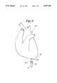
- FIG. 1is a schematic view of a cardioversion/defibrillation system constructed according to the present invention
- FIG. 2is an enlarged view of a proximal end region of the system, along with the proximal end of a device used to deploy the system electrodes;
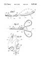
- FIG. 3is an enlarged view of a distal end region of the system and the deployment device
- FIGS. 4-8are diagrammatic views illustrating positioning, release and reconfiguration of a pair of system electrodes
- FIG. 9illustrates an exemplary deployment of the electrodes
- FIG. 10is a distal end region view of an alternative embodiment electrode array constructed according to the present invention.
- FIG. 11is a view of the electrode array contained within a deployment device in a delivery configuration.
- FIGS. 12 and 13are diagrammatic views illustrating an exemplary endocardial deployment of the electrodes.
- FIG. 1a cardioversion/defibrillation system 16 for selectively applying relatively high energy electrical shocks to the heart, a technique frequently referred to as cardioversion.
- a cardiac sensing system(not illustrated) is employed with system 16, for detecting an abnormally rapid cardiac rhythm.
- a high energy shockis discharged through electrodes contiguous with cardiac tissue to depolarize and restore the heart to normal cardiac rhythm.
- System 16includes a cardioversion pulse generator and control unit 18, and two elongate electrical conductors 20 and 22 coupled to the cardioversion control unit at their respective proximal ends 24 and 26.
- An electrode 28is connected to a distal end 30 of a conductor 20.
- an electrode 32is coupled to the distal end 34 of conductor 22. Electrodes 28 and 32 combine to provide an electrode array.
- An electrically insulative coupling sleeve 36secured to respective distal ends 38 and 40 of electrodes 28 and 32, maintains these distal ends proximate to but electrically isolated from one another.
- Conductors 20 and 22are electrically isolated from one another, typically by being encased individually within dielectric tubing, or contained within separate lumens of an insulative catheter.
- each of electrodes 28 and 32is exposed over nearly all of its length, for maximum surface contact with body tissue when the electrodes are implanted.
- insulative sleevessurround the electrodes at their proximal ends, to ensure that when the electrodes assume a loop configuration as illustrated in FIGS. 1 and 9, they are electrically independent of one another.
- the electrodes and dielectric sleevesare constructed of resilient, elastically deformable materials. When in a relaxed state, i.e. when subject to no external stress, these components in cooperation tend to assume a loop configuration, i.e. the single, somewhat circular loop illustrated in FIG. 1. So long as the electrodes remain in the loop configuration, they are physically separated and thus electrically independent from one another.
- electrodes 28 and 32can be employed as a cardioversion/defibrillation pair, with tissue stimulation pulses generated at cardioversion control unit 18 being transmitted from one electrode to the other via body tissue.
- FIGS. 2 and 3illustrate system 16 in greater detail, and show a delivery cannula 74 employed to facilitate body insertion and positioning of electrodes 28 and 32.
- Cardioversion control unit 18includes a cardioversion pulse generating circuit, represented schematically in FIG. 2 at 42. Two receptacles 44 and 46 are electrically coupled to the pulse generating circuit. The control unit further includes pulse or heart rate sensing circuit represented schematically at 48. A pair of receptacles 50 and 52 receive a plug, boots or other appropriate coupling devices to electrically couple a pair of sensing electrodes (not shown) to the control unit. Sensing circuit 48 and cardioversion circuit 42 are operatively coupled to one another, in that when an abnormal rhythm or pulse rate is sensed in sensing circuit 48, cardioversion circuit 42 is triggered to deliver a cardioversion pulse.
- Conductor 20At the proximal end of conductor 20 is a pin 54, surrounded by insulative boot 56.
- Conductor 22similarly includes a pin 58 surrounded by a boot 60.
- Receptacles 44 and 46 in cardioversion control unit 18receive pin 54 and boot 56, and pin 58 and boot 60, respectively, to electrically couple conductors 20 and 22 with the cardioversion pulse generating circuit.
- Each bootincludes ribs or grooves, and is maintained in its associated receptacle in a fluid tight friction fit, to isolate its associated conductor from body fluids.
- conductor 20is surrounded by an electrically insulative and fluid tight sheath 62, and conductor 22 is surrounded by a similar sheath 64.
- Conductors 20 and 22preferably are highly compliant and resistant to fatigue.
- the conductorscan be formed of low resistance composite materials such as drawn braised stranded (DBS) or drawn filled tubes (DFT), coated with platinum or another metal from the platinum group, e.g. iridium, ruthenium or palladium.
- the strandscan be formed of titanium or platinum.
- a suitable DFT conductoris composed of a silver core within a stainless steel tube.
- the conductorscan be single cables or strands as shown, or multiple wires in a twisted or braided arrangement. In any event, the conductors and sheaths are preferably highly compliant and pliable.
- conductors 20 and 22are surrounded by sheaths 68 and 70, which in turn are contained within the lumen of an elongate lead catheter 72.
- Catheter 72is dielectric and highly compliant, and maintains the conductors and sheaths adjacent one another over the length of the catheter. The sheaths electrically isolate the conductors from one another, despite their proximity.
- Catheter 72 and all sheathscan be constructed of a suitable body compatible polymer, e.g. a medical grade silicone rubber or polyurethane.
- FIG. 2illustrates the proximal end of a delivery cannula 74 having a lumen 76 containing the conductors, sheaths and catheter. Also contained within lumen 76 is an inextensible filament 78, preferably constructed of a high tensile strength, body compatible material such as Kevlar (brand) polymer or other synthetic material.
- the delivery cannulasurrounds catheter 72 substantially over the entire catheter length, and extends distally beyond catheter 72 to contain electrodes 28 and 32 as well.
- an anchoring element 80is mounted to the distal end of lead catheter 72, to facilitate securing the lead distal end to body tissue.
- Anchoring element 80can be a conventional polymeric suture sleeve designed to secure the lead distal end to adjacent body tissue using a suture. Or, as shown, anchoring element 80 can be a sleeve provided with one or more tabs for securing the lead end to adjacent tissue using a surgical staple.
- conductors 20 and 22are contained in a reinforcing and strain relief member 82.
- Dielectric sleeves 84 and 86extend distally of the strain relief member, and surround electrodes 28 and 32, respectively, distally of the strain relief member. Each electrode is mechanically and electrically coupled to its associated conductor, either within the strain relief member or within its associated sleeve.
- Electrodes 28 and 32preferably are formed from either single or multi-filar helical coils of titanium wire coated with platinum. Typically, the electrode wires have diameters in the range of 0.005-0.010 inches. The distal end of each electrode is contained within insulative coupling sleeve 36 as indicated in broken lines at 38 and 40, respectively.
- Coupling sleeve 36is a resilient tube, and when in the relaxed state is substantially linear. When not subject to external stresses, coupler sleeve 36 tends to assume its linear configuration. Thus, due to their resilience and their interconnection, electrodes 28 and 32, and sleeves 36, 84 and 86, all cooperate to provide an electrode array that tends to assume the loop configuration illustrated in FIG. 1. When contained in lumen 76, however, sleeves 84 and 86 are biased towards one another, a bend is formed along the medial region 92 of sleeve 36, and electrodes 28 and 32 are brought into close proximity and can contact one another, although shown as spaced apart from one another in FIG. 3.
- Filament 78is secured to medial region 92 of sleeve 36, and extends in the proximal direction through catheter 72 until it emerges from the proximal end of the catheter as shown in FIG. 2.
- the preferred element for securing the filamentis a spherical bead 93 at the distal end of the filament.
- Bead 93preferably is formed of a hard (high durometer) material such as polypropylene, polysulfone, Teflon or glass.
- a receptacle (not shown) in strain relief member 82is open in the direction toward bead 93, and is selectively sized to capture and retain the bead due to friction and an elastic retaining force of the strain relief member.
- One of the salient features of the present inventionis that it enables the simultaneous delivery and deployment of two or more electrically independent biased electrodes employing a minimally invasive subxiphoid or subcostal surgical approach to the pericardial space.
- the procedurebegins with an incision 94 into the body, e.g. a subxiphoid, subcostal or intercostal incision. Tissues between the incision and the pericardium 96 are separated digitally by the surgeon, and a further incision 98 is made in the pericardium.
- Cannula 74containing catheter 72 and the electrodes as illustrated in FIG. 3, is inserted into the pericardium via the incisions. Delivery cannula 74 is then selectively maneuvered, to position distal end 100 of the cannula at a selected location between the heart surface 102 and pericardium 96, for release of the electrodes.
- FIGS. 5-8The electrode release and deployment sequence is illustrated in FIGS. 5-8. While these figures illustrate only the lead and electrodes (without the heart and pericardium) as a matter of convenience, it is to be understood that the sequence occurs with the electrodes positioned at the selected release location near the heart.
- the electrodesare released by moving delivery cannula proximally, while maintaining the position of lead catheter 72, by hand manipulation of the catheter and cannula at their proximal ends.
- lead catheter 72has sufficient axial stiffness to resist axial buckling or compression during proximal movement of cannula 74.
- the cannulaalso has the requisite axial stiffness, and further is provided with a longitudinal or axial slit running distally from its proximal end, to facilitate separation (lateral removal) of the delivery cannula from the lead catheter as the cannula is withdrawn.
- coupling sleeve 36tends to return to a linear shape under its elastic restoring force, spreading the distal regions of electrodes 28 and 32 apart from one another as seen in FIG. 5.
- the electrodes and sleeves, once free of delivery cannula 74,assume the loop configuration shown in FIG. 6.
- the loop configurationconsists of a single loop electrode array 104.
- the pericardiumbears against the electrodes, tending to maintain the electrodes against the epicardial surface, and tending to maintain a relatively flat loop array 104.
- delivery cannula 74can be proximally withdrawn.
- a final electrode implant shapeis achieved by proximally moving filament 78, to draw sleeve 36 proximally against the elastic restoring force of the electrode array. This elastically deforms the electrodes and bends loop 104 as shown in FIG. 7. Continued movement of the filament folds loop 104 over upon itself, with sleeve 36 proximate strain relief member 82 and contacting sleeves 84 and 86, as illustrated in FIG. 8.
- the electrode arraythus is formed into two loops or loop segments, one formed by electrode 28 and the other, by electrode 32.
- the sleevesare of sufficient length to ensure that the electrodes, when in the implant configuration shown in FIG. 8, remain electrically independent of each other.
- the filamentWhen the filament has been withdrawn sufficiently to form the electrode array into the implant configuration, it also has moved sufficiently to position spherical bead 93 within the receptacle of strain relief member 82. An elastic restoring force in the strain relief member tends to retain bead 93 within the receptacle. Thus, the implant configuration is maintained, overcoming an elastic restoring force in electrodes 28 and 32 that otherwise tends to move the electrode array toward the loop configuration. The strain relief member and bead thus cooperate to provide a latching means to maintain the implant configuration.
- FIG. 9illustrates one preferred approach to positioning the electrode assembly. Electrode 28 is positioned epicardially on the left ventricle 106, while electrode 32 is positioned on the right ventricle epicardium 108 through a subxiphoid access to the region (pericardial space) between the pericardium 96 and the heart 102. Because the pericardial space is narrow, the pericardium presses against electrodes 28 and 32, to maintain them in close proximity to the epicardium.
- electrodes 28 and 32 as illustratedhave substantially the same length, this symmetry is not necessary. In fact, it may be advantages to provide an electrode 28 of greater length than electrode 32, due to the larger mass of the left ventricle as compared to the right ventricle.
- the placement procedurealso can involve further movement of the electrode assembly, to optimize the respective electrode positions to the extent possible.
- the distal end of lead catheter 72is secured to body tissue, by suturing anchoring element 80, e.g. with a suture or surgical staple. Because of the manner in which electrodes 28 and 32 are maintained between the heart and pericardium, the suturing the lead distal end sufficiently secures the electrodes as well. There is no need to suture the electrodes.
- the electrodescan be smooth and free of discontinuities, for maximum shock efficiency.
- the complete cardioversion/defibrillation systemmay employ an intravenously inserted electrode 110 at the superior vena cava 112, with tissue stimulating pulses travelling from either electrode 28 at the left ventricle as an anode, to electrode 32 and electrode 110, both as cathodes. Electrode 110, however, is not essential. Electrodes 28 and 32, because they are electrically isolated from one another, can provide the anode and cathode, respectively for pulses travelling from one ventricle to the other.
- FIG. 10shows the distal region of an alternative cardioversion/defibrillation device 116.
- the deviceincludes two conductors 118 and 120, contained within separate lumens of an electrically insulative lead catheter 122.
- An anchoring element 124is provided near the distal end of the lead catheter.
- a pair of electrically insulative sleeves 126 and 128extend from a strain relief member 130 at the lead catheter distal end.
- An elongate flexible coil electrode 132includes a proximal region contained within sleeve 126 and coupled to conductor 118.
- an elongate and flexible coil electrode 134has a proximal portion contained within sleeve 128 and is electrically coupled to conductor 120.
- Respective distal end portions of the electrodesare contained within an electrically insulative and resilient coupling sleeve 140.
- the electrodes and sleevestend to assume a loop configuration, i.e. a loop array 142 as shown in FIG. 10.
- Branch segments 144, 146 and 148are electrically coupled to electrode 132 and project inwardly of loop array 142. Similar linear branch segments 150, 152 and 154 are coupled to electrode 134, and likewise project inwardly of the loop.
- These branch segmentslike the electrodes themselves, are formed of resilient, metallic, helically wound multifilament coils. Preferably, the adjacent branch segments of each electrode interdigitate or extend beyond the free ends of one another, as illustrated in FIG. 10. Regardless of whether the branch segments interdigitate, their inward extension counteracts what is commonly known as "edge effect.” More particularly, each of coil electrodes 132 and 134 has an effective or "phantom" shocking area.
- phantom areasare shown in broken lines at 156 and 158.
- the shocking potential of each coil electrodewould be concentrated along the coil itself, i.e. along the periphery of the phantom area.
- the branch segmentssubstantially reduce this gradient, for a more consistent potential level over the entire phantom area.
- the density or distribution of current flow, through tissue from electrode 132 to electrode 134,is more uniform over the electrode phantom areas, as opposed to current densities much greater near the perimeters of these phantom areas. The result is a more effectively applied tissue stimulation pulse, with less shock strength required for cardioversion.
- a delivery cannula 160is used in the placing and releasing the electrode array.
- the lead catheter, sleeves, and electrodes including branch segmentsare resiliently compressed within a lumen 162 of delivery cannula 160, in the same manner as the previously discussed electrode array.
- Electrodes 132 and 134are inserted into the pericardial space through a subxiphoid or subcostal incision, again in the same manner as previously described.
- FIGS. 12 and 13illustrate one preferred manner of positioning electrodes 132 and 134. Electrode 132 is positioned along the left ventricle 164, with electrode 134 positioned along the right ventricle 166. The pericardium tends to maintain the electrodes against epicardial tissue.
- Electrodes 132 and 134are maintained physically separate from one another by dielectric structure including the sleeves and tube connector. Accordingly, they can be independently and differently biased, to provide a complete cardioversion/defibrillation system.
- an intravenously inserted electrodecan be provided as well, e.g. in the superior vena cava, if desired.
- tissue stimulation electrode configurationsfor other purposes, e.g. cardiac pacing for preventing or terminating tachyarrhythmias, can be constructed according to the present invention.
- the tissue stimulation devicecan incorporate two or more differently polarized electrodes, deployed simultaneously within a single catheter and using minimally invasive surgical procedures. The approach is well suited for deploying several electrodes within the pericardial space, although other locations within the thoracic region can be selected as desired.
- the closed loop electrode configurationis particularly favorable, in that suturing or otherwise anchoring the lead catheter is sufficient to anchor the electrodes, there being no need for hooks, barbs or other auxiliary fasteners along the electrodes themselves.
- the loop configurationalso lends itself well to a selective reshaping of the electrodes after release, for example, using the disclosed inextensible filament.
- electrode branch segmentscan be projected inwardly of the loop, to substantially reduce potential gradients over effective electrode shocking surface areas.
Landscapes
- Health & Medical Sciences (AREA)
- Heart & Thoracic Surgery (AREA)
- Cardiology (AREA)
- Engineering & Computer Science (AREA)
- Biomedical Technology (AREA)
- Nuclear Medicine, Radiotherapy & Molecular Imaging (AREA)
- Radiology & Medical Imaging (AREA)
- Life Sciences & Earth Sciences (AREA)
- Animal Behavior & Ethology (AREA)
- General Health & Medical Sciences (AREA)
- Public Health (AREA)
- Veterinary Medicine (AREA)
- Electrotherapy Devices (AREA)
Abstract
Description
The present invention relates to body implantable tissue stimulation electrodes, e.g. for cardiac pacing or cardioversion/defibrillation, and more particularly to the deployment and implantation of such electrodes.
Heart disease is a major cause of deaths in the United States and in other industrialized nations. One well known treatment approach utilizes an implantable cardiac pacing device, through which relatively mild periodic electrical impulses are applied to epicardial or endocardial tissue as necessary to maintain normal sinus rhythm. More recently, cardioversion/defibrillation devices have been developed to counteract tachyarrhythmias (rapid disturbances in cardiac electrical activity). In particular, the conditions of ventricular tachycardia, ventricular flutter and ventricular fibrillation are widely believed to be the primary cause of sudden deaths associated with heart disease. Defibrillation devices also are utilized to counteract atrial tachyarrhythmic conditions, although such conditions are not considered life threatening unless they lead to a rapid ventricular disturbance.
Tachyarrhythmic conditions frequently can be corrected by applying relatively high energy electrical shocks to the heart, a technique often referred to as cardioversion. Cardioversion devices include implantable electronic standby defibrillators which, in response to the detection of an abnormally rapid cardiac rhythm, discharge sufficient energy through electrodes connected to the heart to depolarize and restore the heart to normal cardiac rhythm.
Cardioversion/defibrillation devices frequently include epicardially implanted electrodes. The surgical procedure required for implantation, i.e. thoracic surgery such as a median sternotomy or thoracotomy, is highly invasive and presents significant risks to the patient. Examples of epicardial defibrillation electrodes are found in U.S. Pat. No. 4,567,900 (Moore), U.S. Pat. No. 4,291,707 (Heilman et al), and U.S. Pat. No. 4,860,769 (Fogarty et al). A pair of differently biased (e.g. oppositely polarized) epicardial electrodes can be employed, as shown in Moore. Alternatively, the Heilman patent discloses an intravenously inserted endocardial electrode arrangement in combination with a patch electrode positioned near the left ventricular apex.
U.S. Pat. No. 4,270,549 (Heilman) describes a technique for inserting and placing defibrillation electrodes, involving intravenous insertion of an endocardial electrode in combination with a patch electrode inserted through a skin incision and through a tunnel created inside the thorax and outside the pleural cavity. Alternatively, U.S. Pat. No. 4,865,037 (Chin et al) discloses a technique for inserting separate electrodes into the intrapericardial space through catheters. An incision is formed in the upper abdominal wall. Then, tissues between the incision and the pericardium are separated, and an incision is then made in the pericardium. A cannula containing a defibrillation electrode is inserted through these incisions, to enable positioning of the electrode in the pericardium. A second cannula containing a second electrode is inserted on the opposite side of the heart, in the same manner.
The above described approaches have enjoyed limited success, yet present risks to patients due to the time and complexity involved. The intravascular approach gives rise to a risk of superior vena cava syndrome, pulmonary embolism, endocardial shock-induced tissue damage, and endocarditis. Left thoracic subcutaneous patches involve discomfort to the patient, and the risk of transcutaneous erosion, subcutaneous infection and fatigue fracture.
Fixation of epicardial electrodes gives rise to difficulties. Active fixation of electrodes, particularly near their free ends, is required to prevent post implantation migration, yet such fixation creates the risk of epicardial lacerations, abrasions and other trauma. Another problem, particularly with patch electrodes, is the current density gradient, i.e. maximum current density regions at the patch periphery. Current density gradients reduce the efficacy of the electrode, in terms of the ratio of useful cardioversion/defibrillation energy as compared to required pulse generator output energy.
Therefore, it is an object of the present invention to provide a tissue stimulation device including two or more differently polarized electrodes, deployable simultaneously using minimally invasive techniques.
Another object is to provide a device for simultaneously deploying multiple, differently biased electrodes within the pericardium.
A further object is to provide a means for deploying an array of resilient electrodes, and for selectively altering the shape of the array following deployment.
Yet another object is to provide an electrode array having a loop configuration and means associated with the loops for reducing current density gradients.
To achieve these and other objects, there is provided a body implantable tissue stimulation device. The device has an electrode array comprising a resilient, elongate and electrically conductive first electrode, an elongate, resilient and electrically conductive second electrode, and an electrically insulative connecting means for securing the first and second electrodes relative to one another. The electrode array tends to assume a loop configuration when in a relaxed state. Each of the electrodes has an exposed exterior surface over a majority of the electrode length. Each electrode further is electrically isolated from the other electrode when the electrode array is in the loop configuration. The stimulation device further includes an elongate and flexible first conductor having a distal end portion electrically coupled to the first electrode. A proximal end of the first conductor is adapted for coupling to an electrical pulse generator, for conducting electrical pulses between the pulse generator and the first electrode. Likewise an elongate and flexible second conductor has a distal end region electrically coupled to the second electrode. A proximal end of the second conductor is adapted for coupling to the pulse generator, for conducting electrical pulses between the pulse generator and the second electrode. The first and second conductors are electrically isolated from one another. An electrode deployment means is operatively associated with the electrode array, for confining the electrode array elastically compressed against a restoring force, i.e. in a delivery configuration. This facilitates a body insertion and delivery of the electrode array to a predetermined stimulation site within the body. The deployment means is controllable from a proximal region of the first and second conductors to effect a release of the electrode array at the stimulation site. Upon release, the electrode array returns to the loop configuration under the restoring force.
Preferably the device further includes a control means coupled to the electrode array for selectively elastically deforming the electrode array, after its release, into a deployment configuration in which a first and second electrodes remain electrically isolated from each other. One advantageous form of control means is a substantially inextensible filament attached at one of its ends to the electrode array and extending proximally along the conductors. When pulled proximally, the filament elastically deforms the electrode array. Then, a latching means secures the filament, to maintain the filament against distal movement responsive to the elastic restoring force in the array.
The device further can include a lead catheter with lumen means for containing the first and second conductors adjacent but electrically isolated from one another. The distal end of the lead catheter is advantageously located at the respective distal end regions of the conductors, to facilitate anchoring of the electrode array with a suture or other securement means at the lead catheter distal end.
The insulative connecting means includes the distal end of the lead catheter. The connecting means further includes an insulative coupler fixed to the respective distal end portions of the first and second electrodes to maintain the distal end portions in spaced apart relation to one another. The inextensible filament preferably is attached to the insulative coupler.
In one advantageous arrangement, the electrodes form a single closed loop when in the loop configuration, and two side by side loops when in the deployment configuration. If desired, one of the loops can be somewhat larger than the other, to facilitate positioning the loops over the apecies of the left and right ventricles.
Another aspect of the present invention is a body implantable tissue stimulation device, including a resilient tissue stimulating electrode means with at least one elongate resilient curvelinear electrode. The electrode has an exposed exterior surface over the majority of its length and is curvelinear when in a relaxed state to define a periphery of a loop. The electrode means further includes a plurality of substantially linear electrode branch segments. Each branch segment is electrically coupled at one end to the curvelinear electrode and directed inwardly of the loop. An elongate and flexible conductor means has a distal end region electrically coupled to the curvelinear electrode. A proximal end of the conductor means is adapted for coupling to an electrical pulse generator for transmitting electrical pulses between the pulse generator and the electrode means. An electrode deployment means is adapted for releasably confining the electrode means in a compressed delivery configuration against an elastic restoring force, thus to facilitate a body insertion and delivery of the electrode means to a predetermined stimulation site within the body. The electrode deployment means is controllable to release the electrode means. Upon release, the electrode means returns to the loop configuration under the restoring force.
The stimulation device is advantageously configured to incorporate several curvelinear electrodes, each with its own set of branch segments. Each of the several electrodes can be electrically isolated from every other electrode, at least when the electrode means is in the relaxed state.
The provision of at least two electrodes, electrically isolated from one another, facilitates the simultaneous deployment of all electrodes necessary for a complete tissue stimulation system for cardioversion/defibrillation. A complete system including pulse generator, differently biased electrodes, and independent leads for conducting pulses between the pulse generator and the respective electrodes, can be implanted in a single surgical procedure, and with a minimally invasive approach utilizing an incision in the subcostal or subxiphoid region. The loop configuration of the electrodes is particularly well suited for electrode positioning within the pericardium. More particularly, the pericardial sack tends to form the electrode loop (or loops) in a flat, wrapping configuration about the heart. The inwardly extending branch segments tend to reduce current density gradients, which improves tissue stimulation shock efficacy for a given pulse generator power level. Finally, the inextensible filament or other tether enables a selective reshaping of the electrodes, following their release, into a configuration suitable for implantation.
For a further understanding of the above and other features and advantages, reference is made to the following detailed description and to the drawings, in which:
FIG. 1 is a schematic view of a cardioversion/defibrillation system constructed according to the present invention;
FIG. 2 is an enlarged view of a proximal end region of the system, along with the proximal end of a device used to deploy the system electrodes;
FIG. 3 is an enlarged view of a distal end region of the system and the deployment device;
FIGS. 4-8 are diagrammatic views illustrating positioning, release and reconfiguration of a pair of system electrodes;
FIG. 9 illustrates an exemplary deployment of the electrodes;
FIG. 10 is a distal end region view of an alternative embodiment electrode array constructed according to the present invention;
FIG. 11 is a view of the electrode array contained within a deployment device in a delivery configuration; and
FIGS. 12 and 13 are diagrammatic views illustrating an exemplary endocardial deployment of the electrodes.
Turning now to the drawings, there is shown in FIG. 1 a cardioversion/defibrillation system 16 for selectively applying relatively high energy electrical shocks to the heart, a technique frequently referred to as cardioversion. Typically a cardiac sensing system (not illustrated) is employed withsystem 16, for detecting an abnormally rapid cardiac rhythm. In response to such detection, a high energy shock is discharged through electrodes contiguous with cardiac tissue to depolarize and restore the heart to normal cardiac rhythm.
An electricallyinsulative coupling sleeve 36, secured to respective distal ends 38 and 40 ofelectrodes Conductors electrodes electrodes cardioversion control unit 18 being transmitted from one electrode to the other via body tissue.
FIGS. 2 and 3 illustratesystem 16 in greater detail, and show adelivery cannula 74 employed to facilitate body insertion and positioning ofelectrodes Cardioversion control unit 18 includes a cardioversion pulse generating circuit, represented schematically in FIG. 2 at 42. Tworeceptacles receptacles Sensing circuit 48 andcardioversion circuit 42 are operatively coupled to one another, in that when an abnormal rhythm or pulse rate is sensed insensing circuit 48,cardioversion circuit 42 is triggered to deliver a cardioversion pulse.
At the proximal end ofconductor 20 is apin 54, surrounded by insulativeboot 56.Conductor 22 similarly includes apin 58 surrounded by aboot 60.Receptacles cardioversion control unit 18 receivepin 54 andboot 56, andpin 58 andboot 60, respectively, to electrically coupleconductors
Distally of the boots,conductor 20 is surrounded by an electrically insulative and fluidtight sheath 62, andconductor 22 is surrounded by asimilar sheath 64.Conductors
Distally of a reinforcing andstrain relief member 66,conductors sheaths elongate lead catheter 72.Catheter 72 is dielectric and highly compliant, and maintains the conductors and sheaths adjacent one another over the length of the catheter. The sheaths electrically isolate the conductors from one another, despite their proximity.Catheter 72 and all sheaths can be constructed of a suitable body compatible polymer, e.g. a medical grade silicone rubber or polyurethane.
FIG. 2 illustrates the proximal end of adelivery cannula 74 having alumen 76 containing the conductors, sheaths and catheter. Also contained withinlumen 76 is aninextensible filament 78, preferably constructed of a high tensile strength, body compatible material such as Kevlar (brand) polymer or other synthetic material. The delivery cannula surroundscatheter 72 substantially over the entire catheter length, and extends distally beyondcatheter 72 to containelectrodes element 80 is mounted to the distal end oflead catheter 72, to facilitate securing the lead distal end to body tissue. Anchoringelement 80 can be a conventional polymeric suture sleeve designed to secure the lead distal end to adjacent body tissue using a suture. Or, as shown, anchoringelement 80 can be a sleeve provided with one or more tabs for securing the lead end to adjacent tissue using a surgical staple. Beyondcatheter 72,conductors strain relief member 82.Dielectric sleeves electrodes
Couplingsleeve 36 is a resilient tube, and when in the relaxed state is substantially linear. When not subject to external stresses,coupler sleeve 36 tends to assume its linear configuration. Thus, due to their resilience and their interconnection,electrodes sleeves lumen 76, however,sleeves medial region 92 ofsleeve 36, andelectrodes
One of the salient features of the present invention is that it enables the simultaneous delivery and deployment of two or more electrically independent biased electrodes employing a minimally invasive subxiphoid or subcostal surgical approach to the pericardial space.
As seen in FIG. 4, the procedure begins with anincision 94 into the body, e.g. a subxiphoid, subcostal or intercostal incision. Tissues between the incision and thepericardium 96 are separated digitally by the surgeon, and afurther incision 98 is made in the pericardium.Cannula 74, containingcatheter 72 and the electrodes as illustrated in FIG. 3, is inserted into the pericardium via the incisions.Delivery cannula 74 is then selectively maneuvered, to positiondistal end 100 of the cannula at a selected location between theheart surface 102 andpericardium 96, for release of the electrodes.
The electrode release and deployment sequence is illustrated in FIGS. 5-8. While these figures illustrate only the lead and electrodes (without the heart and pericardium) as a matter of convenience, it is to be understood that the sequence occurs with the electrodes positioned at the selected release location near the heart.
The electrodes are released by moving delivery cannula proximally, while maintaining the position oflead catheter 72, by hand manipulation of the catheter and cannula at their proximal ends. Thus,lead catheter 72 has sufficient axial stiffness to resist axial buckling or compression during proximal movement ofcannula 74. The cannula also has the requisite axial stiffness, and further is provided with a longitudinal or axial slit running distally from its proximal end, to facilitate separation (lateral removal) of the delivery cannula from the lead catheter as the cannula is withdrawn. Once free of the catheter,coupling sleeve 36 tends to return to a linear shape under its elastic restoring force, spreading the distal regions ofelectrodes delivery cannula 74, assume the loop configuration shown in FIG. 6. The loop configuration consists of a singleloop electrode array 104. During release, the pericardium bears against the electrodes, tending to maintain the electrodes against the epicardial surface, and tending to maintain a relativelyflat loop array 104. At this point,delivery cannula 74 can be proximally withdrawn.
A final electrode implant shape is achieved by proximally movingfilament 78, to drawsleeve 36 proximally against the elastic restoring force of the electrode array. This elastically deforms the electrodes and bendsloop 104 as shown in FIG. 7. Continued movement of the filament foldsloop 104 over upon itself, withsleeve 36 proximatestrain relief member 82 and contactingsleeves electrode 28 and the other, byelectrode 32. The sleeves are of sufficient length to ensure that the electrodes, when in the implant configuration shown in FIG. 8, remain electrically independent of each other. When the filament has been withdrawn sufficiently to form the electrode array into the implant configuration, it also has moved sufficiently to positionspherical bead 93 within the receptacle ofstrain relief member 82. An elastic restoring force in the strain relief member tends to retainbead 93 within the receptacle. Thus, the implant configuration is maintained, overcoming an elastic restoring force inelectrodes
FIG. 9 illustrates one preferred approach to positioning the electrode assembly.Electrode 28 is positioned epicardially on theleft ventricle 106, whileelectrode 32 is positioned on theright ventricle epicardium 108 through a subxiphoid access to the region (pericardial space) between thepericardium 96 and theheart 102. Because the pericardial space is narrow, the pericardium presses againstelectrodes
Whileelectrodes electrode 28 of greater length thanelectrode 32, due to the larger mass of the left ventricle as compared to the right ventricle. The placement procedure also can involve further movement of the electrode assembly, to optimize the respective electrode positions to the extent possible. With the electrode assembly positioned as required, the distal end oflead catheter 72 is secured to body tissue, by suturing anchoringelement 80, e.g. with a suture or surgical staple. Because of the manner in whichelectrodes
If desired, the complete cardioversion/defibrillation system may employ an intravenously insertedelectrode 110 at thesuperior vena cava 112, with tissue stimulating pulses travelling from eitherelectrode 28 at the left ventricle as an anode, toelectrode 32 andelectrode 110, both as cathodes.Electrode 110, however, is not essential.Electrodes
FIG. 10 shows the distal region of an alternative cardioversion/defibrillation device 116. The device includes twoconductors insulative lead catheter 122. Ananchoring element 124 is provided near the distal end of the lead catheter. A pair of electricallyinsulative sleeves strain relief member 130 at the lead catheter distal end. An elongateflexible coil electrode 132 includes a proximal region contained withinsleeve 126 and coupled toconductor 118. Similarly, an elongate andflexible coil electrode 134 has a proximal portion contained withinsleeve 128 and is electrically coupled toconductor 120. Respective distal end portions of the electrodes, indicated at 136 and 138, are contained within an electrically insulative andresilient coupling sleeve 140. In the relaxed state, the electrodes and sleeves tend to assume a loop configuration, i.e. aloop array 142 as shown in FIG. 10.
Several conductive electrode branch segments are provided along each of the electrodes.Branch segments electrode 132 and project inwardly ofloop array 142. Similarlinear branch segments electrode 134, and likewise project inwardly of the loop. These branch segments, like the electrodes themselves, are formed of resilient, metallic, helically wound multifilament coils. Preferably, the adjacent branch segments of each electrode interdigitate or extend beyond the free ends of one another, as illustrated in FIG. 10. Regardless of whether the branch segments interdigitate, their inward extension counteracts what is commonly known as "edge effect." More particularly, each ofcoil electrodes electrode 132 toelectrode 134, is more uniform over the electrode phantom areas, as opposed to current densities much greater near the perimeters of these phantom areas. The result is a more effectively applied tissue stimulation pulse, with less shock strength required for cardioversion.
Adelivery cannula 160 is used in the placing and releasing the electrode array. As seen in FIG. 11, the lead catheter, sleeves, and electrodes including branch segments are resiliently compressed within alumen 162 ofdelivery cannula 160, in the same manner as the previously discussed electrode array.Electrodes positioning electrodes Electrode 132 is positioned along theleft ventricle 164, withelectrode 134 positioned along theright ventricle 166. The pericardium tends to maintain the electrodes against epicardial tissue. The electrode branch segments, having been released fromdelivery cannula 160, resiliently assume their somewhat parallel, interdigitating configuration, withelectrodes Electrodes
All of the preceding embodiments concern cardioversion/defibrillation, for terminating potentially life-threatening tachyarrhythmias. It is to be appreciated that tissue stimulation electrode configurations for other purposes, e.g. cardiac pacing for preventing or terminating tachyarrhythmias, can be constructed according to the present invention. In any event, the tissue stimulation device can incorporate two or more differently polarized electrodes, deployed simultaneously within a single catheter and using minimally invasive surgical procedures. The approach is well suited for deploying several electrodes within the pericardial space, although other locations within the thoracic region can be selected as desired. The closed loop electrode configuration is particularly favorable, in that suturing or otherwise anchoring the lead catheter is sufficient to anchor the electrodes, there being no need for hooks, barbs or other auxiliary fasteners along the electrodes themselves. The loop configuration also lends itself well to a selective reshaping of the electrodes after release, for example, using the disclosed inextensible filament. Finally, electrode branch segments can be projected inwardly of the loop, to substantially reduce potential gradients over effective electrode shocking surface areas.
Claims (20)
1. A body implantable device for conducting tissue stimulation pulses generated by an electrical pulse generator, including:
an electrode array comprising a resilient, elongate and electrically conductive first electrode; an elongate resilient and electrically conductive second electrode; and an electrically insulative connecting means for securing the first and second electrodes relative to one another, said electrode array tending to assume a loop configuration when in a relaxed state, each of the first and second electrodes having an exterior surface exposed over a majority of the electrode length and being electrically isolated from the other electrode when the electrode array is in the loop configuration;
an elongate and flexible first conductor having a distal end portion electrically coupled to the first electrode and a proximal end adapted for coupling to an electrical pulse generator, for conducting electrical pulses between the pulse generator and the first electrode;
an elongate and flexible second conductor having a distal end region electrically coupled to the second electrode and a proximal end adapted for coupling to the pulse generator, for conducting electrical pulses between the pulse generator and the second electrode, said first and second conductors being electrically isolated from one another;
an electrode deployment means operatively associated with the electrode array for confining the electrode array elastically compressed against a restoring force in a delivery configuration to facilitate a body insertion and delivery of the electrode array to a predetermined stimulation site within the body, the deployment means being controllable from along a proximal region of the first and second conductors to effect a release of the electrode array at the stimulation site, whereupon the electrode array returns to the loop configuration under the restoring force; and
a control means coupled to the electrode array for selectively elastically deforming the electrode array, after said release, out of the loop configuration and into an implant configuration in which the first and second electrodes remain electrically isolated from one another.
2. The device of claim 1, wherein:
said electrode array has respective proximal and distal ends, and the control means comprises a substantially inextensible filament attached at a distal end thereof to the electrode array, said filament being moveable proximally relative to the first and second conductors to elastically deform the electrode array into the implant configuration.
3. The device of claim 2 further including:
a latching means for maintaining a proximal portion of the filament and securing the filament against distal movement responsive to an elastic restoring force of the electrode array, thereby to maintain the electrode array in the implant configuration.
4. The device of claim 3 wherein:
said filament has a filament distal end and said first and second conductors have respective first and second distal ends: and the latching means comprises a spherical bead mounted to the filament distal end, and a bead retaining member at the first and second distal ends of said first and second conductors, said bead retaining member including means for capturing and maintaining the bead, to prevent distal movement of the filament, relative to the bead retaining member.
5. The device of claim 1 further including:
a lead catheter containing the first and second conductors and having a lead catheter distal end disposed proximate the distal end portion and distal end region of the first and second conductors respectively.
6. The device of claim 5 further including:
an anchoring means proximate the distal end of the lead catheter, for securing the lead catheter to body tissue.
7. The device of claim 5 wherein:
said first and second electrodes have respective first and second distal end portions; and
the electrically insulative connecting means includes the distal end of the lead catheter and an insulative coupling sleeve fixed to the respective first and second distal end portions of the first and second electrodes to maintain the first and second distal end portions in spaced apart relation to one another.
8. The device of claim 7 further including:
a substantially inextensible filament attached to the insulative coupling sleeve and moveable proximally to move the insulative coupling sleeve proximally following said release, thus to elastically deform the electrode array into an implant configuration in which the first and second electrodes remain electrically isolated from one another.
9. The device of claim 8 further including:
a spherical bead mounted integrally to the inextensible filament and located at least proximate the insulative coupling sleeve, and a bead retaining member at the distal end of the lead catheter for capturing and retaining the bead upon sufficient proximal movement of the filament.
10. The device of claim 8 wherein:
the electrode array forms a single closed loop when in the loop configuration, and forms two loops when in the implant configuration.
11. The device of claim 1 wherein:
the deployment means comprises a deployment cannula having a lumen containing the first and second conductors and further containing the electrode array along a distal region of the deployment cannula, said deployment cannula being slidable proximally relative to the conductors and the electrode array to release the electrode array.
12. The device of claim 1 further including:
a plurality of electrode branch segments, each branch segment coupled at one end to one of the first and second electrodes; and
wherein the electrode array when in the loop configuration forms at least one substantially closed loop, with the branch segments extended inwardly of the at least one closed loop.
13. A body implantable device for conducting tissue stimulation pulses generated by an electrical pulse generator, including:
a resilient electrode means for stimulating tissue including at least one elongate resilient curvelinear electrode having an exposed exterior surface over the majority of its length and curvelinear when in a relaxed state to define a loop, the electrode means further including a plurality of substantially linear electrode branch segments, each branch segment electrically coupled at one end to the curvelinear electrode and directed inwardly of the loop;
an elongate and flexible conductor means having a distal end region electrically coupled to the at least one curvelinear electrode and having a proximal end adapted for coupling to an electrical pulse generator for conducting electrical pulses between the pulse generator and the electrode means; and
an electrode deployment means for releasably confining the electrode means in a compressed delivery configuration against an elastic restoring force, to facilitate a body insertion and delivery of the electrode means to a predetermined stimulation site within the body, the electrode deployment means being controllable to release the electrode means, whereupon the electrode means returns to the relaxed state under the restoring force.
14. The device of claim 13 wherein:
said electrode means includes first and second elongate resilient curvelinear electrodes, and an insulative connecting means for supporting the first and second electrodes with respect to one another and maintaining the first and second electrodes electrically isolated from one another when in the relaxed state;
wherein the conductor means includes elongate and flexible first and second conductors electrically isolated from one another and coupled at respective distal end regions thereof to the first and second curvelinear electrodes, respectively, the conductors further having respective proximal ends adapted for coupling to the pulse generator; and
wherein the plurality of electrode branch segments includes a first set of the branch segments coupled to the first curvelinear electrode, and a second set of the branch segments coupled to the second curvelinear electrode.
15. The device of claim 14 further including:
a lead catheter containing the first and second conductors, with a distal end of the lead catheter proximate the respective distal end regions of the first and second conductors.
16. The device of claim 15 further including:
an anchoring means mounted to the lead catheter near the distal end, for securing the lead catheter to body tissue.
17. A process for implanting a plurality of electrodes epicardially in electrical isolation from one another, including the steps of:
providing a deployment device having a lumen and a distal end with an electrode array comprising a plurality of electrodes contained in the lumen in an elastically compressed delivery configuration, with a plurality of electrical conductors contained in the lumen electrically isolated from one another and proximally of the electrodes and having respective distal end regions, one of the conductors electrically coupled to each of the electrodes;
inserting the distal end of the deployment device into a body through a subxiphoid, subcostal or intercostal incision, and moving the deployment device distally until the distal end enters a pericardial space through a pericardial incision;
positioning the distal end near a predetermined epicardial stimulation site to align the electrodes with the stimulation site;
proximally withdrawing the deployment device while maintaining the electrodes so aligned, to release the electrode array from the deployment device whereupon the electrode array, under an elastic restoring force, assumes a loop configuration in which the electrodes are maintained in electrical isolation from one another at the predetermined epicardial stimulation site; and
following deployment, selectively elastically deforming the electrode array into an implant configuration including a plurality of loops, with the electrodes remaining electrically isolated from one another.
18. The process of claim 17 including the further step of:
following deployment, securing the electrodes against any substantial movement by securing the distal end regions of the conductors to body tissue.
19. The process of claim 17 including the further step of:
anchoring the distal end regions of the conductors to body tissue, to prevent any substantial migration of the electrodes.
20. The process of claim 17 including the further step of:
connecting the respective conductors to different terminals of a pulse generator, and operating the pulse generator to cause transmission of electrical pulses from one of the electrodes to the other via cardiac tissue.
Priority Applications (1)
| Application Number | Priority Date | Filing Date | Title |
|---|---|---|---|
| US08/071,859US5397342A (en) | 1993-06-07 | 1993-06-07 | Resilient structurally coupled and electrically independent electrodes |
Applications Claiming Priority (1)
| Application Number | Priority Date | Filing Date | Title |
|---|---|---|---|
| US08/071,859US5397342A (en) | 1993-06-07 | 1993-06-07 | Resilient structurally coupled and electrically independent electrodes |
Publications (1)
| Publication Number | Publication Date |
|---|---|
| US5397342Atrue US5397342A (en) | 1995-03-14 |
Family
ID=22104066
Family Applications (1)
| Application Number | Title | Priority Date | Filing Date |
|---|---|---|---|
| US08/071,859Expired - LifetimeUS5397342A (en) | 1993-06-07 | 1993-06-07 | Resilient structurally coupled and electrically independent electrodes |
Country Status (1)
| Country | Link |
|---|---|
| US (1) | US5397342A (en) |
Cited By (161)
| Publication number | Priority date | Publication date | Assignee | Title |
|---|---|---|---|---|
| US5643197A (en)* | 1993-12-21 | 1997-07-01 | Angeion Corporation | Fluid cooled and perfused tip for a catheter |
| US5697928A (en)* | 1996-09-23 | 1997-12-16 | Uab Research Foundation | Cardic electrode catheter |
| US5702438A (en)* | 1995-06-08 | 1997-12-30 | Avitall; Boaz | Expandable recording and ablation catheter system |
| US5738683A (en)* | 1994-07-16 | 1998-04-14 | Osypka; Peter | Mapping and ablation catheter |
| US5830209A (en)* | 1992-02-05 | 1998-11-03 | Angeion Corporation | Multi-fiber laser catheter |
| US5836947A (en)* | 1994-10-07 | 1998-11-17 | Ep Technologies, Inc. | Flexible structures having movable splines for supporting electrode elements |
| US5897586A (en)* | 1997-08-15 | 1999-04-27 | Regents Of The University Of Minnesota | Implantable defibrillator lead |
| US5913887A (en)* | 1996-03-01 | 1999-06-22 | Cardiac Pacemakers, Inc. | Device for the transvenous cardioversion of atrial fibrillation or atrial flutter including three coil electrodes |
| US5916243A (en)* | 1992-11-24 | 1999-06-29 | Cardiac Pacemakers, Inc. | Implantable conformal coil patch electrode with multiple conductive elements for cardioversion and defibrillation |
| US5980519A (en)* | 1996-07-30 | 1999-11-09 | Symbiosis Corporation | Electrocautery probe with variable morphology electrode |
| US6071282A (en)* | 1994-10-07 | 2000-06-06 | Ep Technologies, Inc. | Structures for deploying electrode elements |
| US6085119A (en)* | 1998-07-22 | 2000-07-04 | Cardiac Pacemakers, Inc. | Single pass endocardial lead for multi-site atrial pacing |
| US6119043A (en)* | 1995-12-28 | 2000-09-12 | Cardiac Pacemakers, Inc. | Atrial and ventricular cardiac lead having a mechanical bias |
| WO2000066218A1 (en) | 1999-04-30 | 2000-11-09 | Cardiac Pacemakers, Inc. | Implantable cardiac stimulating device with optimized demand |
| US6152954A (en) | 1998-07-22 | 2000-11-28 | Cardiac Pacemakers, Inc. | Single pass lead having retractable, actively attached electrode for pacing and sensing |
| US6205361B1 (en)* | 1998-02-10 | 2001-03-20 | Advanced Bionics Corporation | Implantable expandable multicontact electrodes |
| US6212434B1 (en) | 1998-07-22 | 2001-04-03 | Cardiac Pacemakers, Inc. | Single pass lead system |
| US6321122B1 (en) | 1998-07-22 | 2001-11-20 | Cardiac Pacemakers, Inc. | Single pass defibrillation/pacing lead with passively attached electrode for pacing and sensing |
| US6415187B1 (en)* | 1998-02-10 | 2002-07-02 | Advanced Bionics Corporation | Implantable, expandable, multicontact electrodes and insertion needle for use therewith |
| US6463334B1 (en) | 1998-11-02 | 2002-10-08 | Cardiac Pacemakers, Inc. | Extendable and retractable lead |
| US6501994B1 (en) | 1997-12-24 | 2002-12-31 | Cardiac Pacemakers, Inc. | High impedance electrode tip |
| US6522932B1 (en) | 1998-02-10 | 2003-02-18 | Advanced Bionics Corporation | Implantable, expandable, multicontact electrodes and tools for use therewith |
| US20030149442A1 (en)* | 2002-02-04 | 2003-08-07 | Gellman Barry N. | Resistance heated tissue morcellation |
| US20030204228A1 (en)* | 2002-04-25 | 2003-10-30 | Cross Thomas E. | Surgical lead paddle |
| US6714822B2 (en) | 1998-04-30 | 2004-03-30 | Medtronic, Inc. | Apparatus and method for expanding a stimulation lead body in situ |
| US6795737B2 (en) | 1998-04-30 | 2004-09-21 | Medtronic Inc. | Techniques for positioning therapy delivery elements within a spinal cord or a brain |
| US20040199233A1 (en)* | 2003-04-07 | 2004-10-07 | Cardiac Pacemakers, Inc. | Device and method for a self-attaching suture sleeve |
| US20040199234A1 (en)* | 2003-04-07 | 2004-10-07 | Cardiac Pacemakers, Inc. | Extra strength suture sleeve |
| US20040204728A1 (en)* | 2003-04-11 | 2004-10-14 | Paul Haefner | Ultrasonic subcutaneous dissection tool incorporating fluid delivery |
| US20040204734A1 (en)* | 2003-04-11 | 2004-10-14 | Wagner Darrell Orvin | Tunneling tool with subcutaneous transdermal illumination |
| US20040204735A1 (en)* | 2003-04-11 | 2004-10-14 | Shiroff Jason Alan | Subcutaneous dissection tool incorporating pharmacological agent delivery |
| US20040215240A1 (en)* | 2003-04-11 | 2004-10-28 | Lovett Eric G. | Reconfigurable subcutaneous cardiac device |
| US20040220628A1 (en)* | 2003-04-11 | 2004-11-04 | Wagner Darrell Orvin | Subcutaneous defibrillation timing correlated with induced skeletal muscle contraction |
| US20040220626A1 (en)* | 2003-04-11 | 2004-11-04 | Wagner Darrell Orvin | Distributed subcutaneous defibrillation system |
| US20040220629A1 (en)* | 2003-04-11 | 2004-11-04 | Apurv Kamath | Subcutaneous cardiac sensing and stimulation system employing blood sensor |
| US20040225329A1 (en)* | 2003-04-11 | 2004-11-11 | Wagner Darrell Orvin | Electrode placement determination for subcutaneous cardiac monitoring and therapy |
| US20040230280A1 (en)* | 2003-04-11 | 2004-11-18 | Cates Adam W. | Helical fixation elements for subcutaneous electrodes |
| US20040230230A1 (en)* | 2003-04-11 | 2004-11-18 | Lindstrom Curtis Charles | Methods and systems involving subcutaneous electrode positioning relative to a heart |
| US20040230281A1 (en)* | 2003-04-11 | 2004-11-18 | Ron Heil | Expandable fixation elements for subcutaneous electrodes |
| US20040230272A1 (en)* | 2003-04-11 | 2004-11-18 | Cates Adam W. | Subcutaneous lead with temporary pharmacological agents |
| US20040230274A1 (en)* | 2003-04-11 | 2004-11-18 | Ron Heil | Subcutaneous electrode and lead with phoresis based pharmacological agent delivery |
| US20040230243A1 (en)* | 2003-04-11 | 2004-11-18 | Paul Haefner | Noise canceling cardiac electrodes |
| US20040230129A1 (en)* | 2003-04-11 | 2004-11-18 | Paul Haefner | Multi-parameter arrhythmia discrimination |
| US20040254623A1 (en)* | 2003-06-12 | 2004-12-16 | Cardiac Pacemakers, Inc. | Star suture sleeve |
| US20050004615A1 (en)* | 2003-04-11 | 2005-01-06 | Sanders Richard S. | Reconfigurable implantable cardiac monitoring and therapy delivery device |
| US20050061323A1 (en)* | 2003-09-18 | 2005-03-24 | Cardiac Pacemakers, Inc. | Methods and systems for control of gas therapy |
| US20050061319A1 (en)* | 2003-09-18 | 2005-03-24 | Cardiac Pacemakers, Inc. | Methods and systems for implantably monitoring external breathing therapy |
| US20050065560A1 (en)* | 2003-09-18 | 2005-03-24 | Cardiac Pacemakers, Inc. | Snoring detection system and method |
| US20050065448A1 (en)* | 2003-09-18 | 2005-03-24 | Cardiac Pacemakers, Inc. | Methods and systems for assessing pulmonary disease |
| US20050061315A1 (en)* | 2003-09-18 | 2005-03-24 | Kent Lee | Feedback system and method for sleep disordered breathing therapy |
| US20050061320A1 (en)* | 2003-09-18 | 2005-03-24 | Cardiac Pacemakers, Inc. | Coordinated use of respiratory and cardiac therapies for sleep disordered breathing |
| US20050065572A1 (en)* | 2003-09-18 | 2005-03-24 | Cardiac Pacemakers, Inc. | Diagnosis and/or therapy using blood chemistry/expired gas parameter analysis |
| US20050065567A1 (en)* | 2003-09-18 | 2005-03-24 | Cardiac Pacemakers, Inc. | Therapy control based on cardiopulmonary status |
| US20050074741A1 (en)* | 2003-09-18 | 2005-04-07 | Kent Lee | System and method for discrimination of central and obstructive disordered breathing events |
| US20050080463A1 (en)* | 2003-09-18 | 2005-04-14 | Stahmann Jeffrey E. | System and method for detecting an involuntary muscle movement disorder |
| US20050076908A1 (en)* | 2003-09-18 | 2005-04-14 | Kent Lee | Autonomic arousal detection system and method |
| US20050080348A1 (en)* | 2003-09-18 | 2005-04-14 | Stahmann Jeffrey E. | Medical event logbook system and method |
| US20050076909A1 (en)* | 2003-09-18 | 2005-04-14 | Stahmann Jeffrey E. | Synergistic use of medical devices for detecting medical disorders |
| US20050080461A1 (en)* | 2003-09-18 | 2005-04-14 | Stahmann Jeffrey E. | System and method for moderating a therapy delivered during sleep using physiologic data acquired during non-sleep |
| US20050085738A1 (en)* | 2003-09-18 | 2005-04-21 | Stahmann Jeffrey E. | Sleep logbook |
| US20050090885A1 (en)* | 2003-10-23 | 2005-04-28 | Medtronic, Inc. | Medical lead and manufacturing method therefor |
| US20050107838A1 (en)* | 2003-09-18 | 2005-05-19 | Lovett Eric G. | Subcutaneous cardiac rhythm management with disordered breathing detection and treatment |
| US20050109338A1 (en)* | 2003-09-18 | 2005-05-26 | Stahmann Jeffrey E. | Cardiac pacing controlled via respiration therapy device |
| US20050115561A1 (en)* | 2003-08-18 | 2005-06-02 | Stahmann Jeffrey E. | Patient monitoring, diagnosis, and/or therapy systems and methods |
| US20050131477A1 (en)* | 2003-12-12 | 2005-06-16 | Meyer Scott A. | Cardiac response classification using retriggerable classification windows |
| US20050131478A1 (en)* | 2003-12-12 | 2005-06-16 | Jaeho Kim | Cardiac response classification using multisite sensing and pacing |
| US20050142070A1 (en)* | 2003-09-18 | 2005-06-30 | Hartley Jesse W. | Methods and systems for assessing pulmonary disease with drug therapy control |
| US20050145246A1 (en)* | 2003-09-18 | 2005-07-07 | Hartley Jesse W. | Posture detection system and method |
| US20050215884A1 (en)* | 2004-02-27 | 2005-09-29 | Greicius Michael D | Evaluation of Alzheimer's disease using an independent component analysis of an individual's resting-state functional MRI |
| US20050288728A1 (en)* | 2004-06-08 | 2005-12-29 | Imad Libbus | Adaptive baroreflex stimulation therapy for disordered breathing |
| US20050288600A1 (en)* | 2004-06-24 | 2005-12-29 | Yi Zhang | Automatic orientation determination for ECG measurements using multiple electrodes |
| US20050288729A1 (en)* | 2004-06-08 | 2005-12-29 | Imad Libbus | Coordinated therapy for disordered breathing including baroreflex modulation |
| US6983185B2 (en) | 1998-07-22 | 2006-01-03 | Cardiac Pacemakers, Inc. | Lead with terminal connector assembly |
| US20060069322A1 (en)* | 2004-09-30 | 2006-03-30 | Yi Zhang | Cardiac activation sequence monitoring and tracking |
| US20060074454A1 (en)* | 2004-09-30 | 2006-04-06 | Freeberg Scott M | Methods and systems for selection of cardiac pacing electrode configurations |
| US7047071B2 (en) | 2003-04-11 | 2006-05-16 | Cardiac Pacemakers, Inc. | Patient stratification for implantable subcutaneous cardiac monitoring and therapy |
| US20060116593A1 (en)* | 2004-11-30 | 2006-06-01 | Yi Zhang | Cardiac activation sequence monitoring for ischemia detection |
| US20060143138A1 (en)* | 2004-12-27 | 2006-06-29 | Fujitsu Limited | Password input method |
| US20060167502A1 (en)* | 2004-12-21 | 2006-07-27 | Haefner Paul A | Positionally adaptable implantable cardiac device |
| US20060195149A1 (en)* | 2005-02-28 | 2006-08-31 | Hopper Donald L | Implantable cardiac device with dyspnea measurement |
| US7117035B2 (en) | 2003-04-11 | 2006-10-03 | Cardiac Pacemakers, Inc. | Subcutaneous cardiac stimulation system with patient activity sensing |
| US20060241711A1 (en)* | 2005-04-26 | 2006-10-26 | Sathaye Alok S | Implantable cardiac device and method for reduced phrenic nerve stimulation |
| US20060253162A1 (en)* | 2005-05-09 | 2006-11-09 | Yi Zhang | Closed loop cardiac resynchronization therapy using cardiac activation sequence information |
| US20060253164A1 (en)* | 2005-05-09 | 2006-11-09 | Yi Zhang | Automatic capture verification using electrocardiograms sensed from multiple implanted electrodes |
| US20060253043A1 (en)* | 2005-05-09 | 2006-11-09 | Yi Zhang | Posture monitoring using cardiac activation sequences |
| US20060253042A1 (en)* | 2005-05-04 | 2006-11-09 | Stahmann Jeffrey E | Syncope logbook and method of using same |
| US20060253044A1 (en)* | 2005-05-09 | 2006-11-09 | Yi Zhang | Arrhythmia discrimination using electrocardiograms sensed from multiple implanted electrodes |
| US20070049975A1 (en)* | 2005-09-01 | 2007-03-01 | Cates Adam W | Active can with dedicated defibrillation and sensing electrodes |
| US20070055115A1 (en)* | 2005-09-08 | 2007-03-08 | Jonathan Kwok | Characterization of sleep disorders using composite patient data |
| US20070065363A1 (en)* | 2005-09-16 | 2007-03-22 | Dalal Yousufali H | Quantifying hemodynamic response to drug therapy using implantable sensor |
| US20070073168A1 (en)* | 2005-09-16 | 2007-03-29 | Yi Zhang | Rapid shallow breathing detection for use in congestive heart failure status determination |
| US20070073181A1 (en)* | 2005-09-16 | 2007-03-29 | Yachuan Pu | Respiration monitoring using respiration rate variability |
| US20070073169A1 (en)* | 2005-09-16 | 2007-03-29 | Averina Viktoria A | System and method for generating a trend parameter based on respiration rate distribution |
| US20070118180A1 (en)* | 2005-11-18 | 2007-05-24 | Quan Ni | Cardiac resynchronization therapy for improved hemodynamics based on disordered breathing detection |
| US20070135725A1 (en)* | 2005-12-14 | 2007-06-14 | John Hatlestad | Systems and methods for determining respiration metrics |
| US20070135847A1 (en)* | 2005-12-12 | 2007-06-14 | Kenknight Bruce H | Subcutaneous defibrillation system and method using same |
| US20070142732A1 (en)* | 2005-12-20 | 2007-06-21 | Marina Brockway | Detection of heart failure decompensation based on cumulative changes in sensor signals |
| US7236819B2 (en) | 2003-04-11 | 2007-06-26 | Cardiac Pacemakers, Inc. | Separation of a subcutaneous cardiac signal from a plurality of composite signals |
| US20070239057A1 (en)* | 2006-03-29 | 2007-10-11 | Yanchuan Pu | Periodic disordered breathing detection |
| US20070239244A1 (en)* | 2006-04-11 | 2007-10-11 | Pacesetter, Inc. | Intrapericardial lead |
| US20080004665A1 (en)* | 2006-06-29 | 2008-01-03 | Mccabe Aaron R | Determination of cardiac pacing parameters based on non-localized sensing |
| US20080009909A1 (en)* | 2006-06-29 | 2008-01-10 | Sathaye Alok S | Local and non-local sensing for cardiac pacing |
| WO2007124731A3 (en)* | 2006-05-01 | 2008-01-31 | Neue Magnetodyn Gmbh | Stimulation device for osteosynthesis and endoprosthetics |
| US20080071318A1 (en)* | 2006-09-14 | 2008-03-20 | Brooke M Jason | Therapeutic electrical stimulation that avoids undesirable activation |
| US7392081B2 (en) | 2003-02-28 | 2008-06-24 | Cardiac Pacemakers, Inc. | Subcutaneous cardiac stimulator employing post-shock transthoracic asystole prevention pacing |
| US20080154324A1 (en)* | 2003-12-11 | 2008-06-26 | Cardiac Pacemakers, Inc. | Cardiac response classification using multiple classification windows |
| US20080221468A1 (en)* | 2003-08-18 | 2008-09-11 | Stahmann Jeffrey E | Prediction of disordered breathing |
| US20080228093A1 (en)* | 2007-03-13 | 2008-09-18 | Yanting Dong | Systems and methods for enhancing cardiac signal features used in morphology discrimination |
| US20080275522A1 (en)* | 2003-12-11 | 2008-11-06 | Yanting Dong | Non-captured intrinsic discrimination in cardiac pacing response classification |
| WO2008153717A2 (en) | 2007-05-23 | 2008-12-18 | Cardiac Pacemakers, Inc. | Decongestive therapy titration for heart failure patients using implantable sensor |
| US7479114B2 (en) | 2005-12-01 | 2009-01-20 | Cardiac Pacemakers, Inc. | Determining blood gas saturation based on measured parameter of respiration |
| US20090043351A1 (en)* | 2007-08-07 | 2009-02-12 | Sathaye Alok S | Method and apparatus to perform electrode combination selection |
| US7493175B2 (en) | 2003-04-11 | 2009-02-17 | Cardiac Pacemakers, Inc. | Subcutaneous lead with tined fixation |
| US20090105778A1 (en)* | 2003-05-28 | 2009-04-23 | Kent Lee | Cardiac Waveform Template Creation, Maintenance and Use |
| US7529592B2 (en) | 2003-04-11 | 2009-05-05 | Cardiac Pacemakers, Inc. | Subcutaneous electrode and lead with temporary pharmacological agents |
| US20090163973A1 (en)* | 2005-04-28 | 2009-06-25 | Meyer Scott A | Cardiac Signal Template Generation Using Waveform Clustering |
| US7555335B2 (en) | 2003-04-11 | 2009-06-30 | Cardiac Pacemakers, Inc. | Biopotential signal source separation using source impedances |
| US7570997B2 (en) | 2003-04-11 | 2009-08-04 | Cardiac Pacemakers, Inc. | Subcutaneous cardiac rhythm management with asystole prevention therapy |
| US20090210024A1 (en)* | 2008-02-14 | 2009-08-20 | M Brooke Jason | Method and Apparatus for Phrenic Stimulation Detection |
| US20090234240A1 (en)* | 2008-01-22 | 2009-09-17 | Kuenzler Richard O | Respiration as a Trigger for Therapy Optimization |
| US7599741B2 (en) | 2006-06-29 | 2009-10-06 | Cardiac Pacemakers, Inc. | Systems and methods for improving heart rate kinetics in heart failure patients |
| US7668591B2 (en) | 2003-09-18 | 2010-02-23 | Cardiac Pacemakers, Inc. | Automatic activation of medical processes |
| US7678061B2 (en) | 2003-09-18 | 2010-03-16 | Cardiac Pacemakers, Inc. | System and method for characterizing patient respiration |
| US7715915B1 (en) | 2006-12-22 | 2010-05-11 | Pacesetter, Inc. | Neurostimulation and neurosensing techniques to optimize atrial anti-tachycardia pacing for prevention of atrial tachyarrhythmias |
| US20100174335A1 (en)* | 2003-08-18 | 2010-07-08 | Stahmann Jeffrey E | Therapy Triggered by Predication of Disordered Breathing |
| US20100179613A1 (en)* | 2003-08-18 | 2010-07-15 | Stahmann Jeffrey E | Adaptive Therapy for Disordered Breathing |
| US7766840B2 (en) | 2005-12-01 | 2010-08-03 | Cardiac Pacemakers, Inc. | Method and system for heart failure status evaluation based on a disordered breathing index |
| US7826899B1 (en)* | 2006-12-22 | 2010-11-02 | Pacesetter, Inc. | Neurostimulation and neurosensing techniques to optimize atrial anti-tachycardia pacing for termination of atrial tachyarrhythmias |
| US20100280583A1 (en)* | 2009-04-29 | 2010-11-04 | Biotronik Crm Patent Ag | Electrode Element, Electrode Lead Comprising An Electrode Element, Method For The Production Of An Electrode Lead |
| US7865233B2 (en) | 2003-04-11 | 2011-01-04 | Cardiac Pacemakers, Inc. | Subcutaneous cardiac signal discrimination employing non-electrophysiologic signal |
| US20110009760A1 (en)* | 2009-07-10 | 2011-01-13 | Yi Zhang | Hospital Readmission Alert for Heart Failure Patients |
| US7887493B2 (en) | 2003-09-18 | 2011-02-15 | Cardiac Pacemakers, Inc. | Implantable device employing movement sensing for detecting sleep-related disorders |
| US7920928B1 (en)* | 2007-01-31 | 2011-04-05 | Pacesetter, Inc. | Passive fixation for epicardial lead |
| US7949411B1 (en) | 2007-01-23 | 2011-05-24 | Pacesetter, Inc. | Epicardial lead |
| US7979122B2 (en) | 2003-04-11 | 2011-07-12 | Cardiac Pacemakers, Inc. | Implantable sudden cardiac death prevention device with reduced programmable feature set |
| EP1898999A4 (en)* | 2005-07-01 | 2011-10-19 | Proteus Biomedical Inc | Deployable epicardial electrode and sensor array |
| US20120022551A1 (en)* | 2009-04-03 | 2012-01-26 | Douglas Staunton | Delivery assembly for percutaneously delivering and deploying an electrode array at a target location, the assembly capable of steering the electrode array to the target location |
| US8116868B2 (en) | 2003-04-11 | 2012-02-14 | Cardiac Pacemakers, Inc. | Implantable device with cardiac event audio playback |
| US8224459B1 (en) | 2004-04-30 | 2012-07-17 | Boston Scientific Neuromodulation Corporation | Insertion tool for paddle-style electrode |
| US8706259B2 (en) | 2004-04-30 | 2014-04-22 | Boston Scientific Neuromodulation Corporation | Insertion tool for paddle-style electrode |
| US20140121674A1 (en)* | 2011-05-27 | 2014-05-01 | Stryker Corporation | Assembly for percutaneously inserting an implantable medical device, steering the device to a target location and deploying the device |
| US8948867B2 (en) | 2006-09-14 | 2015-02-03 | Cardiac Pacemakers, Inc. | Capture detection with cross chamber backup pacing |
| US9037239B2 (en) | 2007-08-07 | 2015-05-19 | Cardiac Pacemakers, Inc. | Method and apparatus to perform electrode combination selection |
| US9138151B2 (en) | 2007-03-14 | 2015-09-22 | Cardiac Pacemakers, Inc. | Method and apparatus for management of heart failure hospitalization |
| US9700714B2 (en) | 2013-12-20 | 2017-07-11 | Medtronic, Inc. | Methods and devices for inhibiting tissue growth from restricting a strain relief loop of an implantable medical lead |
| US9743889B2 (en) | 2013-08-05 | 2017-08-29 | Cardiac Pacemakers, Inc. | System and method for detecting worsening of heart failure based on rapid shallow breathing index |
| US9867981B2 (en) | 2013-12-04 | 2018-01-16 | Boston Scientific Neuromodulation Corporation | Insertion tool for implanting a paddle lead and methods and systems utilizing the tool |
| US9956000B2 (en) | 2015-01-13 | 2018-05-01 | Boston Scientific Neuromodulation Corporation | Insertion tool for implanting a paddle lead and methods and systems utilizing the tool |
| US10206710B2 (en) | 2011-11-10 | 2019-02-19 | Medtronic, Inc. | Introduction and anchoring tool for an implantable medical device element |
| US10661080B2 (en) | 2016-04-01 | 2020-05-26 | Kobara Medical Inc. | Shaped epicardial lead and placement system and method |
| US10716500B2 (en) | 2015-06-29 | 2020-07-21 | Cardiac Pacemakers, Inc. | Systems and methods for normalization of chemical sensor data based on fluid state changes |
| US11154207B2 (en) | 2015-12-14 | 2021-10-26 | Medtronic, Inc. | Implantable medical sensor and fixation system |
| US11338135B2 (en) | 2017-10-23 | 2022-05-24 | Cardiac Pacemakers, Inc. | Medical devices for cancer therapy with electric field shaping elements |
| US11420049B2 (en) | 2019-04-22 | 2022-08-23 | Boston Scientific Scimed, Inc. | Systems for administering electrical stimulation to treat cancer |
| US11607542B2 (en) | 2019-04-23 | 2023-03-21 | Boston Scientific Scimed, Inc. | Electrical stimulation for cancer treatment with internal and external electrodes |
| US11691006B2 (en) | 2019-04-22 | 2023-07-04 | Boston Scientific Scimed, Inc. | Electrical stimulation devices for cancer treatment |
| US11712561B2 (en) | 2019-04-23 | 2023-08-01 | Boston Scientific Scimed, Inc. | Electrical stimulation with thermal treatment or thermal monitoring |
| US11850422B2 (en) | 2019-04-23 | 2023-12-26 | Boston Scientific Scimed, Inc. | Electrodes for electrical stimulation to treat cancer |
| US11883655B2 (en) | 2020-02-24 | 2024-01-30 | Boston Scientific Scimed, Inc. | Systems and methods for treatment of pancreatic cancer |
| US12109412B2 (en) | 2019-04-22 | 2024-10-08 | Boston Scientific Scimed, Inc. | Combination electrical and chemotherapeutic treatment of cancer |
| US12403306B2 (en) | 2017-10-23 | 2025-09-02 | Cardiac Pacemakers, Inc. | Electric field shaping leads for treatment of cancer |
Citations (19)
| Publication number | Priority date | Publication date | Assignee | Title |
|---|---|---|---|---|
| US3333045A (en)* | 1965-07-20 | 1967-07-25 | Gen Electric | Body implantable electrical conductor |
| US3472234A (en)* | 1967-08-15 | 1969-10-14 | Gen Electric | Body organ electrode |
| EP0009732A1 (en)* | 1978-10-06 | 1980-04-16 | Precimed S.A. | Catheter for a heart pace-maker |
| US4270549A (en)* | 1979-04-30 | 1981-06-02 | Mieczyslaw Mirowski | Method for implanting cardiac electrodes |
| US4567900A (en)* | 1984-06-04 | 1986-02-04 | Moore J Paul | Internal deployable defibrillator electrode |
| EP0211166A2 (en)* | 1985-06-28 | 1987-02-25 | Peter Dr. Ing. Osypka | Defibrillation electrode |
| US4662377A (en)* | 1985-11-07 | 1987-05-05 | Mieczyslaw Mirowski | Cardioverting method and apparatus utilizing catheter and patch electrodes |
| US4699147A (en)* | 1985-09-25 | 1987-10-13 | Cordis Corporation | Intraventricular multielectrode cardial mapping probe and method for using same |
| US4865037A (en)* | 1987-11-13 | 1989-09-12 | Thomas J. Fogarty | Method for implanting automatic implantable defibrillator |
| US4938231A (en)* | 1985-10-22 | 1990-07-03 | Telectronics N.V. | Defibrillator electrode |
| US4971070A (en)* | 1987-06-18 | 1990-11-20 | Medtronic, Inc. | Epicardial patch electrode |
| US4998975A (en)* | 1989-10-30 | 1991-03-12 | Siemens-Pacesetter, Inc. | Travenously placed defibrillation leads |
| EP0417031A2 (en)* | 1989-09-08 | 1991-03-13 | FOGARTY, Thomas J. | Improved method and apparatus for providing intrapericardial access and inserting intrapericardial electrodes |
| US5010894A (en)* | 1988-01-07 | 1991-04-30 | Edhag Knut O | Intravascular electrode lead usable for cardiac defibrillation |
| US5042463A (en)* | 1990-05-23 | 1991-08-27 | Siemens-Pacesetter, Inc. | Patch electrode for heart defibrillator |
| US5044375A (en)* | 1989-12-08 | 1991-09-03 | Cardiac Pacemakers, Inc. | Unitary intravascular defibrillating catheter with separate bipolar sensing |
| US5052407A (en)* | 1988-04-14 | 1991-10-01 | Mieczyslaw Mirowski | Cardiac defibrillation/cardioversion spiral patch electrode |
| EP0479435A2 (en)* | 1990-10-01 | 1992-04-08 | Ventritex, Inc. | Multiple electrode deployable lead |
| US5107834A (en)* | 1991-01-30 | 1992-04-28 | Cardiac Pacemakers, Inc. | Low energy multiple shock defibrillation/cardioversion discharge technique and electrode configuration |
- 1993
- 1993-06-07USUS08/071,859patent/US5397342A/ennot_activeExpired - Lifetime
Patent Citations (20)
| Publication number | Priority date | Publication date | Assignee | Title |
|---|---|---|---|---|
| US3333045A (en)* | 1965-07-20 | 1967-07-25 | Gen Electric | Body implantable electrical conductor |
| US3472234A (en)* | 1967-08-15 | 1969-10-14 | Gen Electric | Body organ electrode |
| EP0009732A1 (en)* | 1978-10-06 | 1980-04-16 | Precimed S.A. | Catheter for a heart pace-maker |
| US4270549A (en)* | 1979-04-30 | 1981-06-02 | Mieczyslaw Mirowski | Method for implanting cardiac electrodes |
| US4567900A (en)* | 1984-06-04 | 1986-02-04 | Moore J Paul | Internal deployable defibrillator electrode |
| EP0211166A2 (en)* | 1985-06-28 | 1987-02-25 | Peter Dr. Ing. Osypka | Defibrillation electrode |
| US4699147A (en)* | 1985-09-25 | 1987-10-13 | Cordis Corporation | Intraventricular multielectrode cardial mapping probe and method for using same |
| US4938231A (en)* | 1985-10-22 | 1990-07-03 | Telectronics N.V. | Defibrillator electrode |
| US4662377A (en)* | 1985-11-07 | 1987-05-05 | Mieczyslaw Mirowski | Cardioverting method and apparatus utilizing catheter and patch electrodes |
| US4971070A (en)* | 1987-06-18 | 1990-11-20 | Medtronic, Inc. | Epicardial patch electrode |
| US4865037A (en)* | 1987-11-13 | 1989-09-12 | Thomas J. Fogarty | Method for implanting automatic implantable defibrillator |
| US5033477A (en)* | 1987-11-13 | 1991-07-23 | Thomas J. Fogarty | Method and apparatus for providing intrapericardial access and inserting intrapericardial electrodes |
| US5010894A (en)* | 1988-01-07 | 1991-04-30 | Edhag Knut O | Intravascular electrode lead usable for cardiac defibrillation |
| US5052407A (en)* | 1988-04-14 | 1991-10-01 | Mieczyslaw Mirowski | Cardiac defibrillation/cardioversion spiral patch electrode |
| EP0417031A2 (en)* | 1989-09-08 | 1991-03-13 | FOGARTY, Thomas J. | Improved method and apparatus for providing intrapericardial access and inserting intrapericardial electrodes |
| US4998975A (en)* | 1989-10-30 | 1991-03-12 | Siemens-Pacesetter, Inc. | Travenously placed defibrillation leads |
| US5044375A (en)* | 1989-12-08 | 1991-09-03 | Cardiac Pacemakers, Inc. | Unitary intravascular defibrillating catheter with separate bipolar sensing |
| US5042463A (en)* | 1990-05-23 | 1991-08-27 | Siemens-Pacesetter, Inc. | Patch electrode for heart defibrillator |
| EP0479435A2 (en)* | 1990-10-01 | 1992-04-08 | Ventritex, Inc. | Multiple electrode deployable lead |
| US5107834A (en)* | 1991-01-30 | 1992-04-28 | Cardiac Pacemakers, Inc. | Low energy multiple shock defibrillation/cardioversion discharge technique and electrode configuration |
Non-Patent Citations (2)
| Title |
|---|
| Berens et al., "New Stable . . . Pacing Loop", American Journal of Cardiology, vol. 34, Sep. 1974, pp. 325-332. |
| Berens et al., New Stable . . . Pacing Loop , American Journal of Cardiology, vol. 34, Sep. 1974, pp. 325 332.* |
Cited By (361)
| Publication number | Priority date | Publication date | Assignee | Title |
|---|---|---|---|---|
| US5830209A (en)* | 1992-02-05 | 1998-11-03 | Angeion Corporation | Multi-fiber laser catheter |
| US6152955A (en)* | 1992-11-24 | 2000-11-28 | Cardiac Pacemakers, Inc. | Implantable conformal coil patch electrode with multiple conductive elements for cardioversion and defibrillation |
| US5916243A (en)* | 1992-11-24 | 1999-06-29 | Cardiac Pacemakers, Inc. | Implantable conformal coil patch electrode with multiple conductive elements for cardioversion and defibrillation |
| US6038483A (en)* | 1992-11-24 | 2000-03-14 | Cardiac Pacemakers, Inc. | Implantable conformal coil patch electrode with multiple conductive elements for cardioversion and defibrillation |
| US6032079A (en)* | 1992-11-24 | 2000-02-29 | Cardiac Pacemakers, Inc. | Implantable conformal coil electrode with multiple conductive elements for cardioversion and defibrillation |
| US6026332A (en)* | 1992-11-24 | 2000-02-15 | Cardiac Pacemakers, Inc. | Implantable conformal coil patch electrode with multiple conductive elements for cardioversion and defibrillation |
| US5643197A (en)* | 1993-12-21 | 1997-07-01 | Angeion Corporation | Fluid cooled and perfused tip for a catheter |
| US5738683A (en)* | 1994-07-16 | 1998-04-14 | Osypka; Peter | Mapping and ablation catheter |
| US6893439B2 (en) | 1994-10-07 | 2005-05-17 | Ep Technologies, Inc. | Structures and methods for deploying electrode elements |
| US5836947A (en)* | 1994-10-07 | 1998-11-17 | Ep Technologies, Inc. | Flexible structures having movable splines for supporting electrode elements |
| US6544262B2 (en) | 1994-10-07 | 2003-04-08 | Ep Technologies, Inc. | Structures and methods for deploying electrode elements |
| US6071282A (en)* | 1994-10-07 | 2000-06-06 | Ep Technologies, Inc. | Structures for deploying electrode elements |
| US6214002B1 (en) | 1994-10-07 | 2001-04-10 | Ep Technologies, Inc. | Structures and methods for deploying electrode elements |
| US6939349B2 (en) | 1994-10-07 | 2005-09-06 | Ep Technologies, Inc. | Structures for deploying electrode elements |
| US5702438A (en)* | 1995-06-08 | 1997-12-30 | Avitall; Boaz | Expandable recording and ablation catheter system |
| US6119043A (en)* | 1995-12-28 | 2000-09-12 | Cardiac Pacemakers, Inc. | Atrial and ventricular cardiac lead having a mechanical bias |
| US6438416B1 (en) | 1996-03-01 | 2002-08-20 | Cardiac Pacemakers, Inc. | Device for the transvenous cardioversion of atrial fibrillation or atrial flutter including three coil electrodes |
| US7366574B2 (en) | 1996-03-01 | 2008-04-29 | Cardiac Pacemakers, Inc. | Device for the transvenous cardioversion of atrial fibrillation or atrial flutter |
| US6041256A (en)* | 1996-03-01 | 2000-03-21 | Cardiac Pacemakers, Inc. | Device for the transvenous cardioversion of atrial fibrillation or atrial flutter |
| US20040193240A1 (en)* | 1996-03-01 | 2004-09-30 | Cardiac Pacemakers, Inc. | Device for the transvenous cardioversion of atrial fibrillation or atrial flutter |
| US6741894B2 (en) | 1996-03-01 | 2004-05-25 | Cardiac Pacemakers, Inc. | Device for the transvenous cardioversion of atrial fibrillation or atrial flutter |
| US5913887A (en)* | 1996-03-01 | 1999-06-22 | Cardiac Pacemakers, Inc. | Device for the transvenous cardioversion of atrial fibrillation or atrial flutter including three coil electrodes |
| US5980519A (en)* | 1996-07-30 | 1999-11-09 | Symbiosis Corporation | Electrocautery probe with variable morphology electrode |
| US5697928A (en)* | 1996-09-23 | 1997-12-16 | Uab Research Foundation | Cardic electrode catheter |
| US5897586A (en)* | 1997-08-15 | 1999-04-27 | Regents Of The University Of Minnesota | Implantable defibrillator lead |
| US20040133259A1 (en)* | 1997-12-24 | 2004-07-08 | Cardiac Pacemakers, Inc. | High impedance electrode tip |
| US6501994B1 (en) | 1997-12-24 | 2002-12-31 | Cardiac Pacemakers, Inc. | High impedance electrode tip |
| US6415187B1 (en)* | 1998-02-10 | 2002-07-02 | Advanced Bionics Corporation | Implantable, expandable, multicontact electrodes and insertion needle for use therewith |
| US6522932B1 (en) | 1998-02-10 | 2003-02-18 | Advanced Bionics Corporation | Implantable, expandable, multicontact electrodes and tools for use therewith |
| US6205361B1 (en)* | 1998-02-10 | 2001-03-20 | Advanced Bionics Corporation | Implantable expandable multicontact electrodes |
| US7376468B2 (en) | 1998-04-30 | 2008-05-20 | Medtronic, Inc. | Apparatus and method for expanding a stimulation lead body in situ |
| US20040236388A1 (en)* | 1998-04-30 | 2004-11-25 | Medtronic, Inc. | Techniques for positioning therapy delivery elements within a spinal cord or brain |
| US20100241179A1 (en)* | 1998-04-30 | 2010-09-23 | Medtronic, Inc. | Techniques for Positioning Therapy Delivery Elements within a Spinal Cord or Brain |
| US8600495B2 (en) | 1998-04-30 | 2013-12-03 | Medtronic, Inc. | Techniques for positioning therapy delivery elements within a spinal cord or brain |
| US8090449B2 (en) | 1998-04-30 | 2012-01-03 | Meadtronic, Inc | Apparatus and method for expanding a stimulation lead body in situ |
| US7191018B2 (en) | 1998-04-30 | 2007-03-13 | Medtronic, Inc. | Techniques for positioning therapy delivery elements within a spinal cord or brain |
| US20040186543A1 (en)* | 1998-04-30 | 2004-09-23 | Medtronic, Inc. | Apparatus and method for expanding a stimulation lead body in situ |
| US6795737B2 (en) | 1998-04-30 | 2004-09-21 | Medtronic Inc. | Techniques for positioning therapy delivery elements within a spinal cord or a brain |
| US6714822B2 (en) | 1998-04-30 | 2004-03-30 | Medtronic, Inc. | Apparatus and method for expanding a stimulation lead body in situ |
| US6983185B2 (en) | 1998-07-22 | 2006-01-03 | Cardiac Pacemakers, Inc. | Lead with terminal connector assembly |
| US20080262587A1 (en)* | 1998-07-22 | 2008-10-23 | Cardiac Pacemakers, Inc | Extendable and retractable lead having a snap-fit terminal connector |
| US8285398B2 (en) | 1998-07-22 | 2012-10-09 | Cardiac Pacemakers, Inc. | Lead with terminal connector assembly |
| US8209035B2 (en) | 1998-07-22 | 2012-06-26 | Cardiac Pacemakers, Inc. | Extendable and retractable lead having a snap-fit terminal connector |
| US6212434B1 (en) | 1998-07-22 | 2001-04-03 | Cardiac Pacemakers, Inc. | Single pass lead system |
| US7774934B2 (en) | 1998-07-22 | 2010-08-17 | Cardiac Pacemakers, Inc. | Method for making a terminal connector |
| US6345204B1 (en) | 1998-07-22 | 2002-02-05 | Cardiac Pacemakers, Inc. | Single pass lead having retractable, actively attached electrode for pacing and sensing |
| US6915169B2 (en) | 1998-07-22 | 2005-07-05 | Cardiac Pacemakers, Inc. | Extendable and retractable lead having a snap-fit terminal connector |
| US6321122B1 (en) | 1998-07-22 | 2001-11-20 | Cardiac Pacemakers, Inc. | Single pass defibrillation/pacing lead with passively attached electrode for pacing and sensing |
| US6085119A (en)* | 1998-07-22 | 2000-07-04 | Cardiac Pacemakers, Inc. | Single pass endocardial lead for multi-site atrial pacing |
| US7392095B2 (en) | 1998-07-22 | 2008-06-24 | Cardiac Pacemakers, Inc. | Extendable and retractable lead having a snap-fit terminal connector |
| US6152954A (en) | 1998-07-22 | 2000-11-28 | Cardiac Pacemakers, Inc. | Single pass lead having retractable, actively attached electrode for pacing and sensing |
| US6505082B1 (en) | 1998-07-22 | 2003-01-07 | Cardiac Pacemakers, Inc. | Single pass lead system |
| US6463334B1 (en) | 1998-11-02 | 2002-10-08 | Cardiac Pacemakers, Inc. | Extendable and retractable lead |
| US6892096B2 (en) | 1999-04-30 | 2005-05-10 | Cardiac Pacemakers, Inc. | Implantable cardiac stimulating device with optimized demand |
| US6353760B1 (en) | 1999-04-30 | 2002-03-05 | Cardiac Pacemakers, Inc. | Implantable cardiac stimulating device with optimized demand |
| WO2000066218A1 (en) | 1999-04-30 | 2000-11-09 | Cardiac Pacemakers, Inc. | Implantable cardiac stimulating device with optimized demand |
| US6317634B1 (en) | 1999-04-30 | 2001-11-13 | Cardiac Pacemakers, Inc. | Implantable cardiac stimulating device with optimized demand |
| US6363283B1 (en) | 1999-04-30 | 2002-03-26 | Cardiac Pacemakers, Inc. | Implantable cardiac stimulating device with optimized demand |
| US20020120302A1 (en)* | 1999-04-30 | 2002-08-29 | Cardiac Pacemakers, Inc. | Implantable cardiac stimulating device with optimized demand |
| US20030149442A1 (en)* | 2002-02-04 | 2003-08-07 | Gellman Barry N. | Resistance heated tissue morcellation |
| US6997926B2 (en) | 2002-02-04 | 2006-02-14 | Boston Scientific Scimed, Inc. | Resistance heated tissue morcellation |
| US20100146783A1 (en)* | 2002-04-25 | 2010-06-17 | Cross Jr Thomas E | Surgical lead paddle |
| US7697995B2 (en) | 2002-04-25 | 2010-04-13 | Medtronic, Inc. | Surgical lead paddle |
| US20030204228A1 (en)* | 2002-04-25 | 2003-10-30 | Cross Thomas E. | Surgical lead paddle |
| US8108051B2 (en) | 2002-04-25 | 2012-01-31 | Medtronic, Inc. | Surgical lead paddle |
| US20090177702A1 (en)* | 2002-12-27 | 2009-07-09 | Stahmann Jeffrey E | Medical Event Logbook System and Method |
| US8323204B2 (en) | 2002-12-27 | 2012-12-04 | Cardiac Pacemakers, Inc. | Medical event logbook system and method |
| US7392081B2 (en) | 2003-02-28 | 2008-06-24 | Cardiac Pacemakers, Inc. | Subcutaneous cardiac stimulator employing post-shock transthoracic asystole prevention pacing |
| US7218972B2 (en) | 2003-04-07 | 2007-05-15 | Cardiac Pacemakers, Inc. | Extra strength suture sleeve |
| US7242986B2 (en) | 2003-04-07 | 2007-07-10 | Cardiac Pacemakers, Inc. | Device and method for a self-attaching suture sleeve |
| US20040199234A1 (en)* | 2003-04-07 | 2004-10-07 | Cardiac Pacemakers, Inc. | Extra strength suture sleeve |
| US20040199233A1 (en)* | 2003-04-07 | 2004-10-07 | Cardiac Pacemakers, Inc. | Device and method for a self-attaching suture sleeve |
| US20040230274A1 (en)* | 2003-04-11 | 2004-11-18 | Ron Heil | Subcutaneous electrode and lead with phoresis based pharmacological agent delivery |
| US7389138B2 (en) | 2003-04-11 | 2008-06-17 | Cardiac Pacemakers, Inc. | Electrode placement determination for subcutaneous cardiac monitoring and therapy |
| US7218966B2 (en) | 2003-04-11 | 2007-05-15 | Cardiac Pacemakers, Inc. | Multi-parameter arrhythmia discrimination |
| US8024039B2 (en) | 2003-04-11 | 2011-09-20 | Cardiac Pacemakers, Inc. | Subcutaneous cardiac sensing and stimulation system employing blood sensor |
| US7996071B2 (en) | 2003-04-11 | 2011-08-09 | Cardiac Pacemakers, Inc. | Biopotential signal source separation using source impedances |
| US7979122B2 (en) | 2003-04-11 | 2011-07-12 | Cardiac Pacemakers, Inc. | Implantable sudden cardiac death prevention device with reduced programmable feature set |
| US7865233B2 (en) | 2003-04-11 | 2011-01-04 | Cardiac Pacemakers, Inc. | Subcutaneous cardiac signal discrimination employing non-electrophysiologic signal |
| US8843196B2 (en) | 2003-04-11 | 2014-09-23 | Cardiac Pacemakers, Inc. | Subcutaneous cardiac sensing and stimulation system |
| US7236819B2 (en) | 2003-04-11 | 2007-06-26 | Cardiac Pacemakers, Inc. | Separation of a subcutaneous cardiac signal from a plurality of composite signals |
| US20050004615A1 (en)* | 2003-04-11 | 2005-01-06 | Sanders Richard S. | Reconfigurable implantable cardiac monitoring and therapy delivery device |
| US20040204728A1 (en)* | 2003-04-11 | 2004-10-14 | Paul Haefner | Ultrasonic subcutaneous dissection tool incorporating fluid delivery |
| US20040230129A1 (en)* | 2003-04-11 | 2004-11-18 | Paul Haefner | Multi-parameter arrhythmia discrimination |
| US7715916B2 (en) | 2003-04-11 | 2010-05-11 | Cardiac Pacemakers, Inc. | Multi-parameter arrhythmia discrimination |
| US7702399B2 (en) | 2003-04-11 | 2010-04-20 | Cardiac Pacemakers, Inc. | Subcutaneous electrode and lead with phoresis based pharmacological agent delivery |
| US20040230243A1 (en)* | 2003-04-11 | 2004-11-18 | Paul Haefner | Noise canceling cardiac electrodes |
| US20090270750A1 (en)* | 2003-04-11 | 2009-10-29 | Apurv Kamath | Biopotential Signal Source Separation Using Source Impedances |
| US7570997B2 (en) | 2003-04-11 | 2009-08-04 | Cardiac Pacemakers, Inc. | Subcutaneous cardiac rhythm management with asystole prevention therapy |
| US20040230272A1 (en)* | 2003-04-11 | 2004-11-18 | Cates Adam W. | Subcutaneous lead with temporary pharmacological agents |
| US7566318B2 (en) | 2003-04-11 | 2009-07-28 | Cardiac Pacemakers, Inc. | Ultrasonic subcutaneous dissection tool incorporating fluid delivery |
| US20040230281A1 (en)* | 2003-04-11 | 2004-11-18 | Ron Heil | Expandable fixation elements for subcutaneous electrodes |
| US20040230230A1 (en)* | 2003-04-11 | 2004-11-18 | Lindstrom Curtis Charles | Methods and systems involving subcutaneous electrode positioning relative to a heart |
| US7555335B2 (en) | 2003-04-11 | 2009-06-30 | Cardiac Pacemakers, Inc. | Biopotential signal source separation using source impedances |
| US7529592B2 (en) | 2003-04-11 | 2009-05-05 | Cardiac Pacemakers, Inc. | Subcutaneous electrode and lead with temporary pharmacological agents |
| US20040204734A1 (en)* | 2003-04-11 | 2004-10-14 | Wagner Darrell Orvin | Tunneling tool with subcutaneous transdermal illumination |
| US20040230280A1 (en)* | 2003-04-11 | 2004-11-18 | Cates Adam W. | Helical fixation elements for subcutaneous electrodes |
| US20040225329A1 (en)* | 2003-04-11 | 2004-11-11 | Wagner Darrell Orvin | Electrode placement determination for subcutaneous cardiac monitoring and therapy |
| US7499758B2 (en) | 2003-04-11 | 2009-03-03 | Cardiac Pacemakers, Inc. | Helical fixation elements for subcutaneous electrodes |
| US7499750B2 (en) | 2003-04-11 | 2009-03-03 | Cardiac Pacemakers, Inc. | Noise canceling cardiac electrodes |
| US7047071B2 (en) | 2003-04-11 | 2006-05-16 | Cardiac Pacemakers, Inc. | Patient stratification for implantable subcutaneous cardiac monitoring and therapy |
| US7493175B2 (en) | 2003-04-11 | 2009-02-17 | Cardiac Pacemakers, Inc. | Subcutaneous lead with tined fixation |
| US20040220629A1 (en)* | 2003-04-11 | 2004-11-04 | Apurv Kamath | Subcutaneous cardiac sensing and stimulation system employing blood sensor |
| US20040220626A1 (en)* | 2003-04-11 | 2004-11-04 | Wagner Darrell Orvin | Distributed subcutaneous defibrillation system |
| US20040220628A1 (en)* | 2003-04-11 | 2004-11-04 | Wagner Darrell Orvin | Subcutaneous defibrillation timing correlated with induced skeletal muscle contraction |
| US7117035B2 (en) | 2003-04-11 | 2006-10-03 | Cardiac Pacemakers, Inc. | Subcutaneous cardiac stimulation system with patient activity sensing |
| US8116868B2 (en) | 2003-04-11 | 2012-02-14 | Cardiac Pacemakers, Inc. | Implantable device with cardiac event audio playback |
| US20040215240A1 (en)* | 2003-04-11 | 2004-10-28 | Lovett Eric G. | Reconfigurable subcutaneous cardiac device |
| US20040204735A1 (en)* | 2003-04-11 | 2004-10-14 | Shiroff Jason Alan | Subcutaneous dissection tool incorporating pharmacological agent delivery |
| US20080091242A1 (en)* | 2003-04-11 | 2008-04-17 | Apurv Kamath | Subcutaneous cardiac sensing and stimulation system employing blood sensor |
| US7349742B2 (en) | 2003-04-11 | 2008-03-25 | Cardiac Pacemakers, Inc. | Expandable fixation elements for subcutaneous electrodes |
| US20070293896A1 (en)* | 2003-04-11 | 2007-12-20 | Paul Haefner | Multi-parameter arrhythmia discrimination |
| US7302294B2 (en) | 2003-04-11 | 2007-11-27 | Cardiac Pacemakers, Inc. | Subcutaneous cardiac sensing and stimulation system employing blood sensor |
| US20090105778A1 (en)* | 2003-05-28 | 2009-04-23 | Kent Lee | Cardiac Waveform Template Creation, Maintenance and Use |
| US9095265B2 (en) | 2003-05-28 | 2015-08-04 | Cardiac Pacemakers, Inc. | Cardiac waveform template creation, maintenance and use |
| US8606357B2 (en) | 2003-05-28 | 2013-12-10 | Cardiac Pacemakers, Inc. | Cardiac waveform template creation, maintenance and use |
| US20040254623A1 (en)* | 2003-06-12 | 2004-12-16 | Cardiac Pacemakers, Inc. | Star suture sleeve |
| US8321022B2 (en) | 2003-08-18 | 2012-11-27 | Cardiac Pacemakers, Inc. | Adaptive therapy for disordered breathing |
| US20080221468A1 (en)* | 2003-08-18 | 2008-09-11 | Stahmann Jeffrey E | Prediction of disordered breathing |
| US20050115561A1 (en)* | 2003-08-18 | 2005-06-02 | Stahmann Jeffrey E. | Patient monitoring, diagnosis, and/or therapy systems and methods |
| US20100174335A1 (en)* | 2003-08-18 | 2010-07-08 | Stahmann Jeffrey E | Therapy Triggered by Predication of Disordered Breathing |
| US20100179613A1 (en)* | 2003-08-18 | 2010-07-15 | Stahmann Jeffrey E | Adaptive Therapy for Disordered Breathing |
| US7787946B2 (en) | 2003-08-18 | 2010-08-31 | Cardiac Pacemakers, Inc. | Patient monitoring, diagnosis, and/or therapy systems and methods |
| US7938782B2 (en) | 2003-08-18 | 2011-05-10 | Cardiac Pacemakers, Inc. | Prediction of disordered breathing |
| US20050080463A1 (en)* | 2003-09-18 | 2005-04-14 | Stahmann Jeffrey E. | System and method for detecting an involuntary muscle movement disorder |
| US8221327B2 (en) | 2003-09-18 | 2012-07-17 | Cardiac Pacemakers, Inc. | Therapy control based on cardiopulmonary status |
| US20050061319A1 (en)* | 2003-09-18 | 2005-03-24 | Cardiac Pacemakers, Inc. | Methods and systems for implantably monitoring external breathing therapy |
| US20050109339A1 (en)* | 2003-09-18 | 2005-05-26 | Stahmann Jeffrey E. | Respiratory therapy control based on cardiac cycle |
| US7678061B2 (en) | 2003-09-18 | 2010-03-16 | Cardiac Pacemakers, Inc. | System and method for characterizing patient respiration |
| US7302295B2 (en) | 2003-09-18 | 2007-11-27 | Cardiac Pacemakers, Inc. | Method and apparatus for mimicking respiratory sinus arrhythmia with cardiac pacing controlled via external respiration therapy device |
| US20050109338A1 (en)* | 2003-09-18 | 2005-05-26 | Stahmann Jeffrey E. | Cardiac pacing controlled via respiration therapy device |
| US20100174207A1 (en)* | 2003-09-18 | 2010-07-08 | Kent Lee | System and Method for Characterizing Patient Respiration |
| US7668591B2 (en) | 2003-09-18 | 2010-02-23 | Cardiac Pacemakers, Inc. | Automatic activation of medical processes |
| US8655446B2 (en) | 2003-09-18 | 2014-02-18 | Cardiac Pacemakers, Inc. | Cardiac pacing controlled via respiration therapy device |
| US8606356B2 (en) | 2003-09-18 | 2013-12-10 | Cardiac Pacemakers, Inc. | Autonomic arousal detection system and method |
| US20050065560A1 (en)* | 2003-09-18 | 2005-03-24 | Cardiac Pacemakers, Inc. | Snoring detection system and method |
| US20080071317A1 (en)* | 2003-09-18 | 2008-03-20 | Stahmann Jeffrey E | Cardiac pacing controlled via respiration therapy device |
| US7664546B2 (en) | 2003-09-18 | 2010-02-16 | Cardiac Pacemakers, Inc. | Posture detection system and method |
| US20050065448A1 (en)* | 2003-09-18 | 2005-03-24 | Cardiac Pacemakers, Inc. | Methods and systems for assessing pulmonary disease |
| US8522779B2 (en) | 2003-09-18 | 2013-09-03 | Cardiac Pacemakers, Inc. | Coordinated use of respiratory and cardiac therapies for sleep disordered breathing |
| US20100174154A1 (en)* | 2003-09-18 | 2010-07-08 | Kent Lee | Therapy Control Based on Cardiopulmonary Status |
| US8380296B2 (en) | 2003-09-18 | 2013-02-19 | Cardiac Pacemakers, Inc. | Automatic activation of medical processes |
| US20050061315A1 (en)* | 2003-09-18 | 2005-03-24 | Kent Lee | Feedback system and method for sleep disordered breathing therapy |
| US20050061320A1 (en)* | 2003-09-18 | 2005-03-24 | Cardiac Pacemakers, Inc. | Coordinated use of respiratory and cardiac therapies for sleep disordered breathing |
| US20050065572A1 (en)* | 2003-09-18 | 2005-03-24 | Cardiac Pacemakers, Inc. | Diagnosis and/or therapy using blood chemistry/expired gas parameter analysis |
| US7662101B2 (en) | 2003-09-18 | 2010-02-16 | Cardiac Pacemakers, Inc. | Therapy control based on cardiopulmonary status |
| US9014819B2 (en) | 2003-09-18 | 2015-04-21 | Cardiac Pacemakers, Inc. | Autonomic arousal detection system and method |
| US8251061B2 (en) | 2003-09-18 | 2012-08-28 | Cardiac Pacemakers, Inc. | Methods and systems for control of gas therapy |
| US9814429B2 (en) | 2003-09-18 | 2017-11-14 | Cardiac Pacemakers, Inc. | System and method for discrimination of central and obstructive disordered breathing events |
| US7757690B2 (en) | 2003-09-18 | 2010-07-20 | Cardiac Pacemakers, Inc. | System and method for moderating a therapy delivered during sleep using physiologic data acquired during non-sleep |
| US7616988B2 (en) | 2003-09-18 | 2009-11-10 | Cardiac Pacemakers, Inc. | System and method for detecting an involuntary muscle movement disorder |
| US20050080348A1 (en)* | 2003-09-18 | 2005-04-14 | Stahmann Jeffrey E. | Medical event logbook system and method |
| US20050065567A1 (en)* | 2003-09-18 | 2005-03-24 | Cardiac Pacemakers, Inc. | Therapy control based on cardiopulmonary status |
| US7610094B2 (en) | 2003-09-18 | 2009-10-27 | Cardiac Pacemakers, Inc. | Synergistic use of medical devices for detecting medical disorders |
| US20080312548A1 (en)* | 2003-09-18 | 2008-12-18 | Hartley Jesse W | Methods and systems for implantably monitoring external breathing therapy |
| US20050074741A1 (en)* | 2003-09-18 | 2005-04-07 | Kent Lee | System and method for discrimination of central and obstructive disordered breathing events |
| US7468040B2 (en) | 2003-09-18 | 2008-12-23 | Cardiac Pacemakers, Inc. | Methods and systems for implantably monitoring external breathing therapy |
| US7469697B2 (en) | 2003-09-18 | 2008-12-30 | Cardiac Pacemakers, Inc. | Feedback system and method for sleep disordered breathing therapy |
| US20100106211A1 (en)* | 2003-09-18 | 2010-04-29 | Kent Lee | Automatic Activation of Medical Processes |
| US8104470B2 (en) | 2003-09-18 | 2012-01-31 | Cardiac Pacemakers, Inc. | Coordinated use of respiratory and cardiac therapies for sleep disordered breathing |
| US20050107838A1 (en)* | 2003-09-18 | 2005-05-19 | Lovett Eric G. | Subcutaneous cardiac rhythm management with disordered breathing detection and treatment |
| US20050076909A1 (en)* | 2003-09-18 | 2005-04-14 | Stahmann Jeffrey E. | Synergistic use of medical devices for detecting medical disorders |
| US20050076908A1 (en)* | 2003-09-18 | 2005-04-14 | Kent Lee | Autonomic arousal detection system and method |
| US7993279B2 (en) | 2003-09-18 | 2011-08-09 | Cardiac Pacemakers, Inc. | Methods and systems for implantably monitoring external breathing therapy |
| US7510531B2 (en) | 2003-09-18 | 2009-03-31 | Cardiac Pacemakers, Inc. | System and method for discrimination of central and obstructive disordered breathing events |
| US20050080461A1 (en)* | 2003-09-18 | 2005-04-14 | Stahmann Jeffrey E. | System and method for moderating a therapy delivered during sleep using physiologic data acquired during non-sleep |
| US7970470B2 (en) | 2003-09-18 | 2011-06-28 | Cardiac Pacemakers, Inc. | Diagnosis and/or therapy using blood chemistry/expired gas parameter analysis |
| US7532934B2 (en) | 2003-09-18 | 2009-05-12 | Cardiac Pacemakers, Inc. | Snoring detection system and method |
| US7967756B2 (en) | 2003-09-18 | 2011-06-28 | Cardiac Pacemakers, Inc. | Respiratory therapy control based on cardiac cycle |
| US20050061323A1 (en)* | 2003-09-18 | 2005-03-24 | Cardiac Pacemakers, Inc. | Methods and systems for control of gas therapy |
| US7591265B2 (en) | 2003-09-18 | 2009-09-22 | Cardiac Pacemakers, Inc. | Coordinated use of respiratory and cardiac therapies for sleep disordered breathing |
| US20050145246A1 (en)* | 2003-09-18 | 2005-07-07 | Hartley Jesse W. | Posture detection system and method |
| US20050142070A1 (en)* | 2003-09-18 | 2005-06-30 | Hartley Jesse W. | Methods and systems for assessing pulmonary disease with drug therapy control |
| US7887493B2 (en) | 2003-09-18 | 2011-02-15 | Cardiac Pacemakers, Inc. | Implantable device employing movement sensing for detecting sleep-related disorders |
| US7572225B2 (en) | 2003-09-18 | 2009-08-11 | Cardiac Pacemakers, Inc. | Sleep logbook |
| US7575553B2 (en) | 2003-09-18 | 2009-08-18 | Cardiac Pacemakers, Inc. | Methods and systems for assessing pulmonary disease |
| US20050085738A1 (en)* | 2003-09-18 | 2005-04-21 | Stahmann Jeffrey E. | Sleep logbook |
| US20050090885A1 (en)* | 2003-10-23 | 2005-04-28 | Medtronic, Inc. | Medical lead and manufacturing method therefor |
| US7437197B2 (en) | 2003-10-23 | 2008-10-14 | Medtronic, Inc. | Medical lead and manufacturing method therefor |
| US20080275522A1 (en)* | 2003-12-11 | 2008-11-06 | Yanting Dong | Non-captured intrinsic discrimination in cardiac pacing response classification |
| US20080154324A1 (en)* | 2003-12-11 | 2008-06-26 | Cardiac Pacemakers, Inc. | Cardiac response classification using multiple classification windows |
| US9008771B2 (en) | 2003-12-11 | 2015-04-14 | Cardiac Pacemakers, Inc. | Non-captured intrinsic discrimination in cardiac pacing response classification |
| US8145310B2 (en) | 2003-12-11 | 2012-03-27 | Cardiac Pacemakers, Inc. | Non-captured intrinsic discrimination in cardiac pacing response classification |
| US8831726B2 (en) | 2003-12-11 | 2014-09-09 | Cardiac Pacemakers, Inc. | Cardiac response classification using multiple classification windows |
| US9993205B2 (en) | 2003-12-12 | 2018-06-12 | Cardiac Pacemakers, Inc. | Cardiac response classification using retriggerable classification windows |
| US7774064B2 (en) | 2003-12-12 | 2010-08-10 | Cardiac Pacemakers, Inc. | Cardiac response classification using retriggerable classification windows |
| US20100256703A1 (en)* | 2003-12-12 | 2010-10-07 | Meyer Scott A | Cardiac Response Classification Using Retriggerable Classification Windows |
| US8843199B2 (en) | 2003-12-12 | 2014-09-23 | Cardiac Pacemakers, Inc. | Cardiac response classification using multisite sensing and pacing |
| US20050131478A1 (en)* | 2003-12-12 | 2005-06-16 | Jaeho Kim | Cardiac response classification using multisite sensing and pacing |
| US9308375B2 (en) | 2003-12-12 | 2016-04-12 | Cardiac Pacemakers, Inc. | Cardiac response classification using multisite sensing and pacing |
| US8521284B2 (en) | 2003-12-12 | 2013-08-27 | Cardiac Pacemakers, Inc. | Cardiac response classification using multisite sensing and pacing |
| US10898142B2 (en) | 2003-12-12 | 2021-01-26 | Cardiac Pacemakers, Inc. | Cardiac response classification using retriggerable classification windows |
| US20050131477A1 (en)* | 2003-12-12 | 2005-06-16 | Meyer Scott A. | Cardiac response classification using retriggerable classification windows |
| US20050215884A1 (en)* | 2004-02-27 | 2005-09-29 | Greicius Michael D | Evaluation of Alzheimer's disease using an independent component analysis of an individual's resting-state functional MRI |
| US8805543B2 (en) | 2004-04-30 | 2014-08-12 | Boston Scientific Neuromodulation Corporation | Insertion tool for paddle-style electrode |
| US8805544B2 (en) | 2004-04-30 | 2014-08-12 | Boston Scientific Neuromodulation Corporation | Insertion tool for paddle-style electrode |
| US8706259B2 (en) | 2004-04-30 | 2014-04-22 | Boston Scientific Neuromodulation Corporation | Insertion tool for paddle-style electrode |
| US8606367B2 (en) | 2004-04-30 | 2013-12-10 | Boston Scientific Neuromodulation Corporation | Insertion tool for paddle-style electrode |
| US8224459B1 (en) | 2004-04-30 | 2012-07-17 | Boston Scientific Neuromodulation Corporation | Insertion tool for paddle-style electrode |
| US7596413B2 (en) | 2004-06-08 | 2009-09-29 | Cardiac Pacemakers, Inc. | Coordinated therapy for disordered breathing including baroreflex modulation |
| US9872987B2 (en) | 2004-06-08 | 2018-01-23 | Cardiac Pacemakers, Inc. | Method and system for treating congestive heart failure |
| US20050288728A1 (en)* | 2004-06-08 | 2005-12-29 | Imad Libbus | Adaptive baroreflex stimulation therapy for disordered breathing |
| US20050288729A1 (en)* | 2004-06-08 | 2005-12-29 | Imad Libbus | Coordinated therapy for disordered breathing including baroreflex modulation |
| US7747323B2 (en) | 2004-06-08 | 2010-06-29 | Cardiac Pacemakers, Inc. | Adaptive baroreflex stimulation therapy for disordered breathing |
| US8442638B2 (en) | 2004-06-08 | 2013-05-14 | Cardiac Pacemakers, Inc. | Adaptive baroreflex stimulation therapy for disordered breathing |
| US7941206B2 (en) | 2004-06-24 | 2011-05-10 | Cardiac Pacemakers, Inc. | Automatic orientation determination for ECG measurements using multiple electrodes |
| US20050288600A1 (en)* | 2004-06-24 | 2005-12-29 | Yi Zhang | Automatic orientation determination for ECG measurements using multiple electrodes |
| US20100198283A1 (en)* | 2004-06-24 | 2010-08-05 | Yi Zhang | Automatic Orientation Determination for ECG Measurements Using Multiple Electrodes |
| US7706866B2 (en) | 2004-06-24 | 2010-04-27 | Cardiac Pacemakers, Inc. | Automatic orientation determination for ECG measurements using multiple electrodes |
| US20060069322A1 (en)* | 2004-09-30 | 2006-03-30 | Yi Zhang | Cardiac activation sequence monitoring and tracking |
| US7647108B2 (en) | 2004-09-30 | 2010-01-12 | Cardiac Pacemakers, Inc. | Methods and systems for selection of cardiac pacing electrode configurations |
| US20060074454A1 (en)* | 2004-09-30 | 2006-04-06 | Freeberg Scott M | Methods and systems for selection of cardiac pacing electrode configurations |
| US7890159B2 (en) | 2004-09-30 | 2011-02-15 | Cardiac Pacemakers, Inc. | Cardiac activation sequence monitoring and tracking |
| US20100298729A1 (en)* | 2004-11-30 | 2010-11-25 | Yi Zhang | Cardiac Activation Sequence Monitoring for Ischemia Detection |
| US20060116593A1 (en)* | 2004-11-30 | 2006-06-01 | Yi Zhang | Cardiac activation sequence monitoring for ischemia detection |
| US8626276B2 (en) | 2004-11-30 | 2014-01-07 | Cardiac Pacemakers, Inc. | Cardiac activation sequence monitoring for ischemia detection |
| US7797036B2 (en) | 2004-11-30 | 2010-09-14 | Cardiac Pacemakers, Inc. | Cardiac activation sequence monitoring for ischemia detection |
| US20060167502A1 (en)* | 2004-12-21 | 2006-07-27 | Haefner Paul A | Positionally adaptable implantable cardiac device |
| US7996072B2 (en) | 2004-12-21 | 2011-08-09 | Cardiac Pacemakers, Inc. | Positionally adaptable implantable cardiac device |
| US20060143138A1 (en)* | 2004-12-27 | 2006-06-29 | Fujitsu Limited | Password input method |
| US20060195149A1 (en)* | 2005-02-28 | 2006-08-31 | Hopper Donald L | Implantable cardiac device with dyspnea measurement |
| US8515535B2 (en) | 2005-02-28 | 2013-08-20 | Cardiac Pacemakers, Inc. | Implantable cardiac device with dyspnea measurement |
| US20100137931A1 (en)* | 2005-02-28 | 2010-06-03 | Hopper Donald L | Implantable Cardiac Device With Dyspnea Measurement |
| US9277885B2 (en) | 2005-02-28 | 2016-03-08 | Cardiac Pacemakers, Inc. | Implantable cardiac device with dyspnea measurement |
| US7680534B2 (en) | 2005-02-28 | 2010-03-16 | Cardiac Pacemakers, Inc. | Implantable cardiac device with dyspnea measurement |
| US8954146B2 (en) | 2005-02-28 | 2015-02-10 | Cardiac Pacemakers, Inc. | Implantable cardiac device with dyspnea measurement |
| US8750992B2 (en) | 2005-02-28 | 2014-06-10 | Cardiac Pacemakers, Inc. | Implantable cardiac device with dyspnea measurement |
| US20080294215A1 (en)* | 2005-04-26 | 2008-11-27 | Sathaye Alok S | Implantable cardiac device for reduced phrenic nerve stimulation |
| US20080300644A1 (en)* | 2005-04-26 | 2008-12-04 | Sathaye Alok S | Method for reducing phrenic nerve stimulation |
| US8185202B2 (en) | 2005-04-26 | 2012-05-22 | Cardiac Pacemakers, Inc. | Implantable cardiac device for reduced phrenic nerve stimulation |
| US20060241711A1 (en)* | 2005-04-26 | 2006-10-26 | Sathaye Alok S | Implantable cardiac device and method for reduced phrenic nerve stimulation |
| US8260421B2 (en) | 2005-04-26 | 2012-09-04 | Cardiac Pacemakers, Inc. | Method for reducing phrenic nerve stimulation |
| US7392086B2 (en) | 2005-04-26 | 2008-06-24 | Cardiac Pacemakers, Inc. | Implantable cardiac device and method for reduced phrenic nerve stimulation |
| US20090163973A1 (en)* | 2005-04-28 | 2009-06-25 | Meyer Scott A | Cardiac Signal Template Generation Using Waveform Clustering |
| US8660638B2 (en) | 2005-05-04 | 2014-02-25 | Cardiac Pacemakers, Inc. | Syncope logbook and method of using same |
| US7630755B2 (en) | 2005-05-04 | 2009-12-08 | Cardiac Pacemakers Inc. | Syncope logbook and method of using same |
| US20060253042A1 (en)* | 2005-05-04 | 2006-11-09 | Stahmann Jeffrey E | Syncope logbook and method of using same |
| US20100056929A1 (en)* | 2005-05-04 | 2010-03-04 | Stahmann Jeffrey E | Syncope Logbook and Method of Using Same |
| US20060253164A1 (en)* | 2005-05-09 | 2006-11-09 | Yi Zhang | Automatic capture verification using electrocardiograms sensed from multiple implanted electrodes |
| US7917196B2 (en) | 2005-05-09 | 2011-03-29 | Cardiac Pacemakers, Inc. | Arrhythmia discrimination using electrocardiograms sensed from multiple implanted electrodes |
| US20060253162A1 (en)* | 2005-05-09 | 2006-11-09 | Yi Zhang | Closed loop cardiac resynchronization therapy using cardiac activation sequence information |
| US20060253043A1 (en)* | 2005-05-09 | 2006-11-09 | Yi Zhang | Posture monitoring using cardiac activation sequences |
| US7457664B2 (en) | 2005-05-09 | 2008-11-25 | Cardiac Pacemakers, Inc. | Closed loop cardiac resynchronization therapy using cardiac activation sequence information |
| US20060253044A1 (en)* | 2005-05-09 | 2006-11-09 | Yi Zhang | Arrhythmia discrimination using electrocardiograms sensed from multiple implanted electrodes |
| US7917215B2 (en) | 2005-05-09 | 2011-03-29 | Cardiac Pacemakers, Inc. | Closed loop cardiac resynchronization therapy using cardiac activation sequence information |
| US7805185B2 (en) | 2005-05-09 | 2010-09-28 | Cardiac Pacemakers, In. | Posture monitoring using cardiac activation sequences |
| US7509170B2 (en) | 2005-05-09 | 2009-03-24 | Cardiac Pacemakers, Inc. | Automatic capture verification using electrocardiograms sensed from multiple implanted electrodes |
| US8116871B2 (en) | 2005-05-09 | 2012-02-14 | Cardiac Pacemakers, Inc. | Automatic capture verification using electrocardiograms sensed from multiple implanted electrodes |
| US20090198301A1 (en)* | 2005-05-09 | 2009-08-06 | Yi Zhang | Automatic Capture Verification using Electrocardiograms Sensed from Multiple Implanted Electrodes |
| EP1898999A4 (en)* | 2005-07-01 | 2011-10-19 | Proteus Biomedical Inc | Deployable epicardial electrode and sensor array |
| US20070049975A1 (en)* | 2005-09-01 | 2007-03-01 | Cates Adam W | Active can with dedicated defibrillation and sensing electrodes |
| US20070055115A1 (en)* | 2005-09-08 | 2007-03-08 | Jonathan Kwok | Characterization of sleep disorders using composite patient data |
| US20070065363A1 (en)* | 2005-09-16 | 2007-03-22 | Dalal Yousufali H | Quantifying hemodynamic response to drug therapy using implantable sensor |
| US20070073168A1 (en)* | 2005-09-16 | 2007-03-29 | Yi Zhang | Rapid shallow breathing detection for use in congestive heart failure status determination |
| US20070073169A1 (en)* | 2005-09-16 | 2007-03-29 | Averina Viktoria A | System and method for generating a trend parameter based on respiration rate distribution |
| US8992436B2 (en) | 2005-09-16 | 2015-03-31 | Cardiac Pacemakers, Inc. | Respiration monitoring using respiration rate variability |
| US7731663B2 (en) | 2005-09-16 | 2010-06-08 | Cardiac Pacemakers, Inc. | System and method for generating a trend parameter based on respiration rate distribution |
| US8372012B2 (en) | 2005-09-16 | 2013-02-12 | Cardiac Pacemakers, Inc. | System and method for generating a trend parameter based on respiration rate distribution |
| US20100228133A1 (en)* | 2005-09-16 | 2010-09-09 | Averina Viktoria A | System and Method for Generating a Trend Parameter Based on Respiration Rate Distribution |
| US7775983B2 (en) | 2005-09-16 | 2010-08-17 | Cardiac Pacemakers, Inc. | Rapid shallow breathing detection for use in congestive heart failure status determination |
| US7927284B2 (en) | 2005-09-16 | 2011-04-19 | Cardiac Pacemakers, Inc. | Quantifying hemodynamic response to drug therapy using implantable sensor |
| US20070073181A1 (en)* | 2005-09-16 | 2007-03-29 | Yachuan Pu | Respiration monitoring using respiration rate variability |
| US11350848B2 (en) | 2005-09-16 | 2022-06-07 | Cardiac Pacemakers, Inc. | System and method for generating a trend parameter based on respiration rate distribution |
| US9931074B2 (en) | 2005-11-18 | 2018-04-03 | Cardiac Pacemakers, Inc. | Cardiac resynchronization therapy for improved hemodynamics based on disordered breathing detection |
| US20070118180A1 (en)* | 2005-11-18 | 2007-05-24 | Quan Ni | Cardiac resynchronization therapy for improved hemodynamics based on disordered breathing detection |
| US7766840B2 (en) | 2005-12-01 | 2010-08-03 | Cardiac Pacemakers, Inc. | Method and system for heart failure status evaluation based on a disordered breathing index |
| US7479114B2 (en) | 2005-12-01 | 2009-01-20 | Cardiac Pacemakers, Inc. | Determining blood gas saturation based on measured parameter of respiration |
| US20070135847A1 (en)* | 2005-12-12 | 2007-06-14 | Kenknight Bruce H | Subcutaneous defibrillation system and method using same |
| US7662105B2 (en) | 2005-12-14 | 2010-02-16 | Cardiac Pacemakers, Inc. | Systems and methods for determining respiration metrics |
| US8496596B2 (en) | 2005-12-14 | 2013-07-30 | Cardiac Pacemakers, Inc. | Systems and methods for determining respiration metrics |
| US8998821B2 (en) | 2005-12-14 | 2015-04-07 | Cardiac Pacemakers, Inc. | Systems and methods for determining respiration metrics |
| US20070135725A1 (en)* | 2005-12-14 | 2007-06-14 | John Hatlestad | Systems and methods for determining respiration metrics |
| US20070142732A1 (en)* | 2005-12-20 | 2007-06-21 | Marina Brockway | Detection of heart failure decompensation based on cumulative changes in sensor signals |
| US7761158B2 (en) | 2005-12-20 | 2010-07-20 | Cardiac Pacemakers, Inc. | Detection of heart failure decompensation based on cumulative changes in sensor signals |
| US20070239057A1 (en)* | 2006-03-29 | 2007-10-11 | Yanchuan Pu | Periodic disordered breathing detection |
| US7819816B2 (en) | 2006-03-29 | 2010-10-26 | Cardiac Pacemakers, Inc. | Periodic disordered breathing detection |
| US20070239244A1 (en)* | 2006-04-11 | 2007-10-11 | Pacesetter, Inc. | Intrapericardial lead |
| US20110106233A1 (en)* | 2006-04-11 | 2011-05-05 | Pacesetter, Inc. | Intrapericardial lead |
| US8406902B2 (en) | 2006-04-11 | 2013-03-26 | Pacesetter, Inc. | Intrapericardial lead with precurved distal end portion |
| US7899555B2 (en) | 2006-04-11 | 2011-03-01 | Pacesetter, Inc. | Intrapericardial lead |
| WO2007124731A3 (en)* | 2006-05-01 | 2008-01-31 | Neue Magnetodyn Gmbh | Stimulation device for osteosynthesis and endoprosthetics |
| AU2007246020B2 (en)* | 2006-05-01 | 2011-04-07 | Neue Magnetodyn Gmbh | Stimulation device for osteosynthesis and endoprosthetics |
| JP2009535134A (en)* | 2006-05-01 | 2009-10-01 | ノイエ マグネートオーデュン ゲーエムベーハー | Stimulation device for osteosynthesis and endoprosthesis |
| US20100036467A1 (en)* | 2006-05-01 | 2010-02-11 | Neue Magnetodyn Gmbh | Stimulation device for osteosynthesis and endoprosthetics |
| CN101437569B (en)* | 2006-05-01 | 2013-08-14 | 新磁有限公司 | Stimulation device for osteosynthesis and endoprosthetics |
| US7599741B2 (en) | 2006-06-29 | 2009-10-06 | Cardiac Pacemakers, Inc. | Systems and methods for improving heart rate kinetics in heart failure patients |
| US8311631B2 (en) | 2006-06-29 | 2012-11-13 | Cardiac Pacemakers, Inc. | Systems and methods for improving heart rate kinetics in heart failure patients |
| US20090312815A1 (en)* | 2006-06-29 | 2009-12-17 | Hopper Donald L | Systems and Methods for Improving Heart Rate Kinetics in Heart Failure Patients |
| US8527048B2 (en) | 2006-06-29 | 2013-09-03 | Cardiac Pacemakers, Inc. | Local and non-local sensing for cardiac pacing |
| US20080009909A1 (en)* | 2006-06-29 | 2008-01-10 | Sathaye Alok S | Local and non-local sensing for cardiac pacing |
| US20080004665A1 (en)* | 2006-06-29 | 2008-01-03 | Mccabe Aaron R | Determination of cardiac pacing parameters based on non-localized sensing |
| US20080071318A1 (en)* | 2006-09-14 | 2008-03-20 | Brooke M Jason | Therapeutic electrical stimulation that avoids undesirable activation |
| US8209013B2 (en) | 2006-09-14 | 2012-06-26 | Cardiac Pacemakers, Inc. | Therapeutic electrical stimulation that avoids undesirable activation |
| US8948867B2 (en) | 2006-09-14 | 2015-02-03 | Cardiac Pacemakers, Inc. | Capture detection with cross chamber backup pacing |
| US20110015690A1 (en)* | 2006-12-22 | 2011-01-20 | Pacesetter, Inc. | Neurostimulation and Neurosensing Techniques to Optimize Atrial Anti-Tachycardia Pacing for Prevention of Atrial Tachyarrhythmias |
| US7715915B1 (en) | 2006-12-22 | 2010-05-11 | Pacesetter, Inc. | Neurostimulation and neurosensing techniques to optimize atrial anti-tachycardia pacing for prevention of atrial tachyarrhythmias |
| US7826899B1 (en)* | 2006-12-22 | 2010-11-02 | Pacesetter, Inc. | Neurostimulation and neurosensing techniques to optimize atrial anti-tachycardia pacing for termination of atrial tachyarrhythmias |
| US8449472B2 (en) | 2006-12-22 | 2013-05-28 | Pacesetter, Inc. | Neurostimulation and neurosensing techniques to optimize atrial anti-tachycardia pacing for prevention of atrial tachyarrhythmias |
| US7949411B1 (en) | 2007-01-23 | 2011-05-24 | Pacesetter, Inc. | Epicardial lead |
| US7920928B1 (en)* | 2007-01-31 | 2011-04-05 | Pacesetter, Inc. | Passive fixation for epicardial lead |
| US9002478B1 (en)* | 2007-01-31 | 2015-04-07 | Pacesetter, Inc. | Passive fixation for epicardial lead |
| US20080228093A1 (en)* | 2007-03-13 | 2008-09-18 | Yanting Dong | Systems and methods for enhancing cardiac signal features used in morphology discrimination |
| US10441179B2 (en) | 2007-03-14 | 2019-10-15 | Cardiac Pacemakers, Inc. | Method and apparatus for management of heart failure hospitalization |
| US9730592B2 (en) | 2007-03-14 | 2017-08-15 | Cardiac Pacemakers, Inc. | Method and apparatus for management of heart failure hospitalization |
| US9138151B2 (en) | 2007-03-14 | 2015-09-22 | Cardiac Pacemakers, Inc. | Method and apparatus for management of heart failure hospitalization |
| US11723544B2 (en) | 2007-03-14 | 2023-08-15 | Cardiac Pacemakers, Inc. | Method and apparatus for management of heart failure hospitalization |
| US10537281B2 (en) | 2007-05-23 | 2020-01-21 | Cardiac Pacemakers, Inc. | Decongestive therapy titration for heart failure patients using implantable sensor |
| WO2008153717A2 (en) | 2007-05-23 | 2008-12-18 | Cardiac Pacemakers, Inc. | Decongestive therapy titration for heart failure patients using implantable sensor |
| US8271080B2 (en) | 2007-05-23 | 2012-09-18 | Cardiac Pacemakers, Inc. | Decongestive therapy titration for heart failure patients using implantable sensor |
| US10080901B2 (en) | 2007-08-07 | 2018-09-25 | Cardiac Pacemakers, Inc. | Method and apparatus to perform electrode combination selection |
| US9533160B2 (en) | 2007-08-07 | 2017-01-03 | Cardiac Pacemakers, Inc. | Method and apparatus to perform electrode combination selection |
| US10022548B2 (en) | 2007-08-07 | 2018-07-17 | Cardiac Pacemakers, Inc. | Method and apparatus to perform electrode combination selection |
| US20090043351A1 (en)* | 2007-08-07 | 2009-02-12 | Sathaye Alok S | Method and apparatus to perform electrode combination selection |
| US9623252B2 (en) | 2007-08-07 | 2017-04-18 | Cardiac Pacemakers, Inc. | Method and apparatus to perform electrode combination selection |
| US9037239B2 (en) | 2007-08-07 | 2015-05-19 | Cardiac Pacemakers, Inc. | Method and apparatus to perform electrode combination selection |
| US9008775B2 (en) | 2007-08-07 | 2015-04-14 | Cardiac Pacemakers, Inc. | Method and apparatus to perform electrode combination selection |
| US9427588B2 (en) | 2007-08-07 | 2016-08-30 | Cardiac Pacemakers, Inc. | Method and apparatus to perform electrode combination selection |
| US8615297B2 (en) | 2007-08-07 | 2013-12-24 | Cardiac Pacemakers, Inc. | Method and apparatus to perform electrode combination selection |
| US8265736B2 (en) | 2007-08-07 | 2012-09-11 | Cardiac Pacemakers, Inc. | Method and apparatus to perform electrode combination selection |
| US9539429B2 (en) | 2007-08-07 | 2017-01-10 | Cardiac Pacemakers, Inc. | Method and apparatus to perform electrode combination selection |
| US8983602B2 (en) | 2007-08-07 | 2015-03-17 | Cardiac Pacemakers, Inc. | Method and apparatus to perform electrode combination selection |
| US11857795B2 (en) | 2007-08-07 | 2024-01-02 | Cardiac Pacemakers, Inc. | Method and apparatus to perform electrode combination selection |
| US9079033B2 (en) | 2008-01-22 | 2015-07-14 | Cardiac Pacemakers, Inc. | Respiration as a trigger for therapy optimization |
| US20090234240A1 (en)* | 2008-01-22 | 2009-09-17 | Kuenzler Richard O | Respiration as a Trigger for Therapy Optimization |
| US9555253B2 (en) | 2008-02-14 | 2017-01-31 | Cardiac Pacemakers, Inc. | Method and apparatus for phrenic stimulation detection |
| US9352160B2 (en) | 2008-02-14 | 2016-05-31 | Cardiac Pacemakers, Inc. | Method and apparatus for phrenic stimulation detection |
| US20090210024A1 (en)* | 2008-02-14 | 2009-08-20 | M Brooke Jason | Method and Apparatus for Phrenic Stimulation Detection |
| US8996112B2 (en) | 2008-02-14 | 2015-03-31 | Cardiac Pacemakers, Inc. | Method and apparatus for phrenic stimulation detection |
| US8649866B2 (en) | 2008-02-14 | 2014-02-11 | Cardiac Pacemakers, Inc. | Method and apparatus for phrenic stimulation detection |
| US9463312B2 (en)* | 2009-04-03 | 2016-10-11 | Stryker Corporation | Delivery assembly for percutaneously delivering and deploying an electrode array at a target location, the assembly capable of steering the electrode array to the target location |
| US10046159B2 (en) | 2009-04-03 | 2018-08-14 | Stryker Corporation | Delivery assembly for percutaneously delivering and deploying an electrode array at a target location, the assembly including a steerable core around which the array is wrapped |
| US10842533B2 (en) | 2009-04-03 | 2020-11-24 | Stryker Corporation | Delivery assembly for percutaneously delivering and deploying an electrode array at a target location, the assembly including a steerable core around which the array is wrapped |
| US20120022551A1 (en)* | 2009-04-03 | 2012-01-26 | Douglas Staunton | Delivery assembly for percutaneously delivering and deploying an electrode array at a target location, the assembly capable of steering the electrode array to the target location |
| US20100280583A1 (en)* | 2009-04-29 | 2010-11-04 | Biotronik Crm Patent Ag | Electrode Element, Electrode Lead Comprising An Electrode Element, Method For The Production Of An Electrode Lead |
| DE102009002707A1 (en)* | 2009-04-29 | 2010-11-04 | Biotronik Crm Patent Ag | Electrode element, electrode line with an electrode element and manufacturing method of an electrode line |
| US20110009760A1 (en)* | 2009-07-10 | 2011-01-13 | Yi Zhang | Hospital Readmission Alert for Heart Failure Patients |
| US20140121674A1 (en)* | 2011-05-27 | 2014-05-01 | Stryker Corporation | Assembly for percutaneously inserting an implantable medical device, steering the device to a target location and deploying the device |
| US9655645B2 (en)* | 2011-05-27 | 2017-05-23 | Stryker Corporation | Assembly for percutaneously inserting an implantable medical device, steering the device to a target location and deploying the device |
| US10463398B2 (en) | 2011-05-27 | 2019-11-05 | Stryker Corporation | Steerable introducer assembly for first percutaneously identifying target tissue and then defining a percutaneous path to the target tissue for an implantable medical device |
| US10206710B2 (en) | 2011-11-10 | 2019-02-19 | Medtronic, Inc. | Introduction and anchoring tool for an implantable medical device element |
| US10987134B2 (en) | 2011-11-10 | 2021-04-27 | Medtronic, Inc. | Introduction and anchoring tool for an implantable medical device element |
| US9743889B2 (en) | 2013-08-05 | 2017-08-29 | Cardiac Pacemakers, Inc. | System and method for detecting worsening of heart failure based on rapid shallow breathing index |
| US10384055B2 (en) | 2013-12-04 | 2019-08-20 | Boston Scientific Neuromodulation Corporation | Insertion tool for implanting a paddle lead and methods and systems utilizing the tool |
| US9867981B2 (en) | 2013-12-04 | 2018-01-16 | Boston Scientific Neuromodulation Corporation | Insertion tool for implanting a paddle lead and methods and systems utilizing the tool |
| US9700714B2 (en) | 2013-12-20 | 2017-07-11 | Medtronic, Inc. | Methods and devices for inhibiting tissue growth from restricting a strain relief loop of an implantable medical lead |
| US9956000B2 (en) | 2015-01-13 | 2018-05-01 | Boston Scientific Neuromodulation Corporation | Insertion tool for implanting a paddle lead and methods and systems utilizing the tool |
| US10716500B2 (en) | 2015-06-29 | 2020-07-21 | Cardiac Pacemakers, Inc. | Systems and methods for normalization of chemical sensor data based on fluid state changes |
| US11154207B2 (en) | 2015-12-14 | 2021-10-26 | Medtronic, Inc. | Implantable medical sensor and fixation system |
| US12193799B2 (en) | 2015-12-14 | 2025-01-14 | Medtronic, Inc. | Implantable medical sensor and fixation system |
| US10661080B2 (en) | 2016-04-01 | 2020-05-26 | Kobara Medical Inc. | Shaped epicardial lead and placement system and method |
| US11338135B2 (en) | 2017-10-23 | 2022-05-24 | Cardiac Pacemakers, Inc. | Medical devices for cancer therapy with electric field shaping elements |
| US12403306B2 (en) | 2017-10-23 | 2025-09-02 | Cardiac Pacemakers, Inc. | Electric field shaping leads for treatment of cancer |
| US11691006B2 (en) | 2019-04-22 | 2023-07-04 | Boston Scientific Scimed, Inc. | Electrical stimulation devices for cancer treatment |
| US12109412B2 (en) | 2019-04-22 | 2024-10-08 | Boston Scientific Scimed, Inc. | Combination electrical and chemotherapeutic treatment of cancer |
| US12311168B2 (en) | 2019-04-22 | 2025-05-27 | Boston Scientific Scimed, Inc. | Electrical stimulation devices for cancer treatment |
| US11420049B2 (en) | 2019-04-22 | 2022-08-23 | Boston Scientific Scimed, Inc. | Systems for administering electrical stimulation to treat cancer |
| US11850422B2 (en) | 2019-04-23 | 2023-12-26 | Boston Scientific Scimed, Inc. | Electrodes for electrical stimulation to treat cancer |
| US11712561B2 (en) | 2019-04-23 | 2023-08-01 | Boston Scientific Scimed, Inc. | Electrical stimulation with thermal treatment or thermal monitoring |
| US12186553B2 (en) | 2019-04-23 | 2025-01-07 | Boston Scientific Scimed, Inc. | Electrical stimulation for cancer treatment with internal and external electrodes |
| US11607542B2 (en) | 2019-04-23 | 2023-03-21 | Boston Scientific Scimed, Inc. | Electrical stimulation for cancer treatment with internal and external electrodes |
| US11883655B2 (en) | 2020-02-24 | 2024-01-30 | Boston Scientific Scimed, Inc. | Systems and methods for treatment of pancreatic cancer |
Similar Documents
| Publication | Publication Date | Title |
|---|---|---|
| US5397342A (en) | Resilient structurally coupled and electrically independent electrodes | |
| US5282845A (en) | Multiple electrode deployable lead | |
| US5545205A (en) | Unitary intravascular defibrillating catheter with bipolar sensing | |
| US7272448B1 (en) | Medical lead for placement in the pericardial sac | |
| AU629503B2 (en) | Transvenously placed defibrillation leads | |
| US5693081A (en) | Endocardial lead system with defibrillation electrode fixation | |
| US5897586A (en) | Implantable defibrillator lead | |
| US5366496A (en) | Subcutaneous shunted coil electrode | |
| US7899554B2 (en) | Intravascular System and Method | |
| US9561106B2 (en) | Cardiac access methods and apparatus | |
| EP0526671B1 (en) | Unitary intravascular defibrillating catheter with separate bipolar sensing | |
| US8055355B2 (en) | System and assembly having conductive fixation features | |
| EP0590431B1 (en) | A foldable defibrillation patch electrode with a conductor-free zone which acts as a hinge | |
| US5527358A (en) | Temporary medical electrical lead | |
| EP0965359A2 (en) | Transvenous defibrillation lead system for use in middle cardiac vein | |
| EP0095727A1 (en) | Method and apparatus for inserting a defibrillator electrode and defibrillator electrode | |
| JPH0571269B2 (en) | ||
| EP0095726B1 (en) | Apparatus for controlling cardiac ventricular tachyarrhythmias | |
| US12311165B2 (en) | Implantable endovascular, low profile intracardiac left atrial restraining devices for low energy atrial cardioversion, pacing and sensing | |
| US5713944A (en) | Cardioversion-defibrillation catheter lead having selectively exposable outer conductors | |
| US20230191142A1 (en) | Implantable medical lead shield | |
| US20250186788A1 (en) | Implantable medical lead with shield | |
| US20250065112A1 (en) | Implantable medical lead with shield | |
| US20070106358A1 (en) | Tissue stimulating lead and method of implantation and manufacture | |
| JPH05115567A (en) | Remover for thin movement in blood vessel |
Legal Events
| Date | Code | Title | Description |
|---|---|---|---|
| AS | Assignment | Owner name:CARDIAC PACEMAKERS, INC., MINNESOTA Free format text:ASSIGNMENT OF ASSIGNORS INTEREST;ASSIGNORS:WICKMAN, ROBERT W., JR. (DECEASED);QUIGGLE, DUANE R., ADMINISTRATOR OF MR. WICKMAN'S ESTATE;REEL/FRAME:006600/0234 Effective date:19930512 Owner name:CARDIAC PACEMAKERS, INC., MINNESOTA Free format text:ASSIGNMENT OF ASSIGNORS INTEREST;ASSIGNORS:HEIL, RONALD W., JR.;KENKNIGHT, BRUCE H.;REEL/FRAME:006600/0230 Effective date:19930426 | |
| STPP | Information on status: patent application and granting procedure in general | Free format text:APPLICATION UNDERGOING PREEXAM PROCESSING | |
| CC | Certificate of correction | ||
| FPAY | Fee payment | Year of fee payment:4 | |
| REMI | Maintenance fee reminder mailed | ||
| FEPP | Fee payment procedure | Free format text:PAYOR NUMBER ASSIGNED (ORIGINAL EVENT CODE: ASPN); ENTITY STATUS OF PATENT OWNER: LARGE ENTITY | |
| FPAY | Fee payment | Year of fee payment:8 | |
| SULP | Surcharge for late payment | Year of fee payment:7 | |
| FPAY | Fee payment | Year of fee payment:12 |