US5397205A - Rivet fastener and method of installing - Google Patents
Rivet fastener and method of installingDownload PDFInfo
- Publication number
- US5397205A US5397205AUS08/172,786US17278693AUS5397205AUS 5397205 AUS5397205 AUS 5397205AUS 17278693 AUS17278693 AUS 17278693AUS 5397205 AUS5397205 AUS 5397205A
- Authority
- US
- United States
- Prior art keywords
- rivet
- nut
- components
- shell
- fastener
- Prior art date
- Legal status (The legal status is an assumption and is not a legal conclusion. Google has not performed a legal analysis and makes no representation as to the accuracy of the status listed.)
- Expired - Lifetime
Links
- 238000000034methodMethods0.000titleclaimsdescription10
- XAGFODPZIPBFFR-UHFFFAOYSA-NaluminiumChemical compound[Al]XAGFODPZIPBFFR-UHFFFAOYSA-N0.000claimsabstractdescription3
- 229910052782aluminiumInorganic materials0.000claimsabstractdescription3
- 238000003780insertionMethods0.000claimsabstractdescription3
- 230000037431insertionEffects0.000claimsabstractdescription3
- AZDRQVAHHNSJOQ-UHFFFAOYSA-NalumaneChemical group[AlH3]AZDRQVAHHNSJOQ-UHFFFAOYSA-N0.000description2
- 239000000463materialSubstances0.000description1
- 239000007779soft materialSubstances0.000description1
Images
Classifications
- F—MECHANICAL ENGINEERING; LIGHTING; HEATING; WEAPONS; BLASTING
- F16—ENGINEERING ELEMENTS AND UNITS; GENERAL MEASURES FOR PRODUCING AND MAINTAINING EFFECTIVE FUNCTIONING OF MACHINES OR INSTALLATIONS; THERMAL INSULATION IN GENERAL
- F16B—DEVICES FOR FASTENING OR SECURING CONSTRUCTIONAL ELEMENTS OR MACHINE PARTS TOGETHER, e.g. NAILS, BOLTS, CIRCLIPS, CLAMPS, CLIPS OR WEDGES; JOINTS OR JOINTING
- F16B19/00—Bolts without screw-thread; Pins, including deformable elements; Rivets
- F16B19/04—Rivets; Spigots or the like fastened by riveting
- F16B19/05—Bolts fastening by swaged-on collars
- B—PERFORMING OPERATIONS; TRANSPORTING
- B21—MECHANICAL METAL-WORKING WITHOUT ESSENTIALLY REMOVING MATERIAL; PUNCHING METAL
- B21J—FORGING; HAMMERING; PRESSING METAL; RIVETING; FORGE FURNACES
- B21J15/00—Riveting
- B21J15/02—Riveting procedures
- Y—GENERAL TAGGING OF NEW TECHNOLOGICAL DEVELOPMENTS; GENERAL TAGGING OF CROSS-SECTIONAL TECHNOLOGIES SPANNING OVER SEVERAL SECTIONS OF THE IPC; TECHNICAL SUBJECTS COVERED BY FORMER USPC CROSS-REFERENCE ART COLLECTIONS [XRACs] AND DIGESTS
- Y10—TECHNICAL SUBJECTS COVERED BY FORMER USPC
- Y10T—TECHNICAL SUBJECTS COVERED BY FORMER US CLASSIFICATION
- Y10T29/00—Metal working
- Y10T29/49—Method of mechanical manufacture
- Y10T29/49826—Assembling or joining
- Y10T29/49908—Joining by deforming
- Y10T29/49938—Radially expanding part in cavity, aperture, or hollow body
- Y10T29/4994—Radially expanding internal tube
- Y—GENERAL TAGGING OF NEW TECHNOLOGICAL DEVELOPMENTS; GENERAL TAGGING OF CROSS-SECTIONAL TECHNOLOGIES SPANNING OVER SEVERAL SECTIONS OF THE IPC; TECHNICAL SUBJECTS COVERED BY FORMER USPC CROSS-REFERENCE ART COLLECTIONS [XRACs] AND DIGESTS
- Y10—TECHNICAL SUBJECTS COVERED BY FORMER USPC
- Y10T—TECHNICAL SUBJECTS COVERED BY FORMER US CLASSIFICATION
- Y10T29/00—Metal working
- Y10T29/49—Method of mechanical manufacture
- Y10T29/49826—Assembling or joining
- Y10T29/49947—Assembling or joining by applying separate fastener
- Y10T29/49954—Fastener deformed after application
- Y10T29/49956—Riveting
Definitions
- the present inventionrelates to fasteners in general and in particular to rivet-like fasteners for joining two parts, particularly aluminum parts.
- the former method of joining the parts together using threaded inserts and fastenersis relatively expensive to fabricate and necessitates machinery and tooling for handling the engagement of the threaded fastener which is relatively complex and expensive itself.
- a fastener for joining two aluminum componentswhich employs a nut received in an aperture spanning the two components and a rivet shell and mandrel assembly inserted into the nut and deformed into threaded engagement with the nut through axial loading of the mandrel of the rivet.
- the rivet shellincludes threads formed on its outer diameter to facilitate the threaded engagement between the nut and the rivet shell.
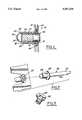
- FIG. 1is a cross-sectional view showing the fastener of the present invention installed to join two components
- FIG. 2is an exploded view showing the mandrel and shell components of the rivet separately from the nut;
- FIG. 3is a perspective view of the rivet shell of the fastener of the present invention in its formed condition.
- the fastener 18includes a relatively deformable nut insert 20 having internal threads 22 and an outer diameter 24 received within the bores 14, 16.
- Carried within the nut 20is a rivet assembly 26 which includes a rivet shell 28 and a rivet mandrel 30.
- An outer diameter 32 of the shell 28may be smooth as illustrated in FIG. 1, or may be threaded.
- an enlarged head portion 36includes a shoulder surface 38 that abuttingly engages the end 40 of the shell 28.
- the enlarged head portion 36may be further enlarged to similarly abuttingly engage the end 42 of the nut 20.
- the rivet assembly 26is preferably of the type commonly referred to as a pop rivet and it includes an annular flange portion 44 on the shell portion 20 for abutting engagement against the component 10 or a similar annular flange 46 which may be provided on the nut 20, as shown in FIG. 1.
- the rivet assembly 26is inserted into the nut 20 and an appropriate tool is used to grip the stem 48 (FIG. 2) of the mandrel 30 while urging it toward the components 10, 12.
- Drawing the stem 48 rightwardly, as viewed in FIG. 1loads the enlarged portion 36 against the shell 28, and in certain application the shell 28 and the nut 20, deforming them both in columnar fashion.
- the shell 28is preferably chosen to be fabricated from a soft material, and deforming it outwardly effects engagement with the internal threads 22 of the nut 20 to define threaded engagement therebetween as indicated at 23 in FIG. 1.
- engagement of the enlarged head 36 against the nut 20may effect columnar deformation which deforms the nut into press fit engagement with one or both of the bores 14, 16.
- a tool receiving slotmay be provided on the flange 44 of the shell 28. This facilitates rotation of the rivet 26 so that removal of the rivet 26 from the nut 20 and consequent removal of the plate 10 from the plate 12 can be effected.
Landscapes
- Engineering & Computer Science (AREA)
- Mechanical Engineering (AREA)
- General Engineering & Computer Science (AREA)
- Insertion Pins And Rivets (AREA)
Abstract
Description
Claims (9)
Priority Applications (2)
| Application Number | Priority Date | Filing Date | Title |
|---|---|---|---|
| US08/172,786US5397205A (en) | 1993-12-27 | 1993-12-27 | Rivet fastener and method of installing |
| DE4433095ADE4433095C2 (en) | 1993-12-27 | 1994-09-16 | Fasteners and method for connecting two components |
Applications Claiming Priority (1)
| Application Number | Priority Date | Filing Date | Title |
|---|---|---|---|
| US08/172,786US5397205A (en) | 1993-12-27 | 1993-12-27 | Rivet fastener and method of installing |
Publications (1)
| Publication Number | Publication Date |
|---|---|
| US5397205Atrue US5397205A (en) | 1995-03-14 |
Family
ID=22629231
Family Applications (1)
| Application Number | Title | Priority Date | Filing Date |
|---|---|---|---|
| US08/172,786Expired - LifetimeUS5397205A (en) | 1993-12-27 | 1993-12-27 | Rivet fastener and method of installing |
Country Status (2)
| Country | Link |
|---|---|
| US (1) | US5397205A (en) |
| DE (1) | DE4433095C2 (en) |
Cited By (9)
| Publication number | Priority date | Publication date | Assignee | Title |
|---|---|---|---|---|
| US20040240961A1 (en)* | 2003-06-02 | 2004-12-02 | Bentrim Brian G. | Floating captivated wrenchable nut |
| US20050089384A1 (en)* | 2003-10-22 | 2005-04-28 | Pratt Adam D. | Fastener with adhesive |
| US6932044B1 (en) | 2004-02-26 | 2005-08-23 | General Fasteners Company | Windage tray with improved captured nut |
| US20090206220A1 (en)* | 2008-02-18 | 2009-08-20 | Earl David Forrest | Method and apparatus for attaching grab bar to wall flange |
| US20100088802A1 (en)* | 2008-10-07 | 2010-04-15 | Level Sport S.R.L. | Glove arranged for coupling to a pole |
| US20120055069A1 (en)* | 2010-04-14 | 2012-03-08 | Alexander Justin Mobile | Rod hugger reel clamp |
| US20150316060A1 (en)* | 2014-05-02 | 2015-11-05 | Lg Electronics Inc. | Compressor |
| US20210231144A1 (en)* | 2018-05-08 | 2021-07-29 | Böllhoff Verbindungstechnik GmbH | Connection between two components with tolerance compensation and a connecting method therefor |
| US12276294B2 (en)* | 2019-05-15 | 2025-04-15 | Howmet Aerospace Inc. | Blind fasteners and methods of fastening |
Families Citing this family (2)
| Publication number | Priority date | Publication date | Assignee | Title |
|---|---|---|---|---|
| DE19646668A1 (en)* | 1996-11-12 | 1998-05-14 | Sfs Ind Holding Ag | Fastener insertable in a blind hole |
| DE102012111491B4 (en) | 2012-11-27 | 2014-06-18 | Sma Solar Technology Ag | Electronic device with electrically conductive lid connection |
Citations (6)
| Publication number | Priority date | Publication date | Assignee | Title |
|---|---|---|---|---|
| US1391447A (en)* | 1920-12-04 | 1921-09-20 | Baron George | Bolt-lock |
| US2036551A (en)* | 1936-04-07 | Ophthalmic mounting and method | ||
| US2083831A (en)* | 1934-03-02 | 1937-06-15 | American Optical Corp | Connecting means |
| US3193858A (en)* | 1961-03-24 | 1965-07-13 | Gen Am Transport | Methods of producing strong threaded anchorages |
| US3319690A (en)* | 1964-01-02 | 1967-05-16 | Rosan Eng Corp | Top driven locking insert |
| US4642010A (en)* | 1983-06-01 | 1987-02-10 | Avdel Limited | Threaded fastener and method of installing same |
Family Cites Families (2)
| Publication number | Priority date | Publication date | Assignee | Title |
|---|---|---|---|---|
| DE1286812B (en)* | 1964-06-04 | 1969-01-09 | Honsel Nieten & Metallwarenfab | Blind rivet assembly |
| DE3619826A1 (en)* | 1986-06-12 | 1987-12-17 | Hirschmann Radiotechnik | Rivet connection |
- 1993
- 1993-12-27USUS08/172,786patent/US5397205A/ennot_activeExpired - Lifetime
- 1994
- 1994-09-16DEDE4433095Apatent/DE4433095C2/ennot_activeExpired - Fee Related
Patent Citations (6)
| Publication number | Priority date | Publication date | Assignee | Title |
|---|---|---|---|---|
| US2036551A (en)* | 1936-04-07 | Ophthalmic mounting and method | ||
| US1391447A (en)* | 1920-12-04 | 1921-09-20 | Baron George | Bolt-lock |
| US2083831A (en)* | 1934-03-02 | 1937-06-15 | American Optical Corp | Connecting means |
| US3193858A (en)* | 1961-03-24 | 1965-07-13 | Gen Am Transport | Methods of producing strong threaded anchorages |
| US3319690A (en)* | 1964-01-02 | 1967-05-16 | Rosan Eng Corp | Top driven locking insert |
| US4642010A (en)* | 1983-06-01 | 1987-02-10 | Avdel Limited | Threaded fastener and method of installing same |
Cited By (11)
| Publication number | Priority date | Publication date | Assignee | Title |
|---|---|---|---|---|
| US20040240961A1 (en)* | 2003-06-02 | 2004-12-02 | Bentrim Brian G. | Floating captivated wrenchable nut |
| US6866456B2 (en) | 2003-06-02 | 2005-03-15 | Pem Management, Inc. | Floating captivated wrenchable nut |
| US20050089384A1 (en)* | 2003-10-22 | 2005-04-28 | Pratt Adam D. | Fastener with adhesive |
| US6932044B1 (en) | 2004-02-26 | 2005-08-23 | General Fasteners Company | Windage tray with improved captured nut |
| US20090206220A1 (en)* | 2008-02-18 | 2009-08-20 | Earl David Forrest | Method and apparatus for attaching grab bar to wall flange |
| US20100088802A1 (en)* | 2008-10-07 | 2010-04-15 | Level Sport S.R.L. | Glove arranged for coupling to a pole |
| US20120055069A1 (en)* | 2010-04-14 | 2012-03-08 | Alexander Justin Mobile | Rod hugger reel clamp |
| US20150316060A1 (en)* | 2014-05-02 | 2015-11-05 | Lg Electronics Inc. | Compressor |
| US20210231144A1 (en)* | 2018-05-08 | 2021-07-29 | Böllhoff Verbindungstechnik GmbH | Connection between two components with tolerance compensation and a connecting method therefor |
| US11933348B2 (en)* | 2018-05-08 | 2024-03-19 | Böllhoff Verbindungstechnik GmbH | Connection between two components with tolerance compensation and a connecting method therefor |
| US12276294B2 (en)* | 2019-05-15 | 2025-04-15 | Howmet Aerospace Inc. | Blind fasteners and methods of fastening |
Also Published As
| Publication number | Publication date |
|---|---|
| DE4433095C2 (en) | 1997-04-17 |
| DE4433095A1 (en) | 1995-06-29 |
Similar Documents
| Publication | Publication Date | Title |
|---|---|---|
| US6488460B1 (en) | Composite panel insert with hold out recess feature | |
| US5294223A (en) | Self-clinching fastener for electrical components | |
| US20060067804A1 (en) | Deforming member and captive fastener retaining method | |
| JP3491279B2 (en) | Caulking nut and manufacturing method thereof | |
| US5397205A (en) | Rivet fastener and method of installing | |
| EP1248911B1 (en) | Quick access rubber panel fastener | |
| KR102557852B1 (en) | Tapered lead-in for interference fit fasteners | |
| EP0797007B1 (en) | Fan and fan drive and assembly thereof | |
| AU632013B1 (en) | Captivating a fastener to a workpiece | |
| WO1995017611A1 (en) | Joint forming device | |
| US5692865A (en) | Quick release fastener system | |
| US20050025605A1 (en) | Locator stud and method of assembly | |
| US20050089384A1 (en) | Fastener with adhesive | |
| US4767248A (en) | Fastener for securing panels of composite materials | |
| US20020067975A1 (en) | Method of attaching a fastener element to a panel and fastener element and panel asssembly | |
| US4919578A (en) | Rivetless nut plate and fastener | |
| JP6765423B2 (en) | Parts holding fasteners mounted at the same height | |
| US5855052A (en) | Fastener installation device | |
| CN113302407B (en) | Fastener for sheet material | |
| US4750600A (en) | Clutch cover | |
| EP1055075B1 (en) | Blind rivet connector | |
| GB2298156A (en) | Fastener for securing panels | |
| JP3295602B2 (en) | Fastening rivets | |
| JP2001173629A (en) | Fastener and fastening method | |
| US12270464B2 (en) | Assembly with riveted components |
Legal Events
| Date | Code | Title | Description |
|---|---|---|---|
| AS | Assignment | Owner name:FORD MOTOR COMPANY, MICHIGAN Free format text:ASSIGNMENT OF ASSIGNORS INTEREST;ASSIGNOR:DIEPEVEEN, ROBERT J.;REEL/FRAME:006887/0696 Effective date:19931217 | |
| STCF | Information on status: patent grant | Free format text:PATENTED CASE | |
| FPAY | Fee payment | Year of fee payment:4 | |
| AS | Assignment | Owner name:FORD GLOBAL TECHNOLOGIES, INC. A MICHIGAN CORPORAT Free format text:ASSIGNMENT OF ASSIGNORS INTEREST;ASSIGNOR:FORD MOTOR COMPANY, A DELAWARE CORPORATION;REEL/FRAME:011467/0001 Effective date:19970301 | |
| FPAY | Fee payment | Year of fee payment:8 | |
| AS | Assignment | Owner name:RESEARCH FOUNDATION, THE, NEW YORK Free format text:ASSIGNMENT OF ASSIGNORS INTEREST;ASSIGNOR:FORD GLOBAL TECHNOLOGIES, INC.;REEL/FRAME:013343/0348 Effective date:20021126 Owner name:RESEARCH FOUNDATION OF STATE UNIVERSITY OF NEW YOR Free format text:ASSIGNMENT OF ASSIGNORS INTEREST;ASSIGNOR:FORD GLOBAL TECHNOLOGIES, INC.;REEL/FRAME:013305/0150 Effective date:20021126 | |
| FPAY | Fee payment | Year of fee payment:12 |