US5396880A - Endoscope for direct visualization of the spine and epidural space - Google Patents
Endoscope for direct visualization of the spine and epidural spaceDownload PDFInfo
- Publication number
- US5396880A US5396880AUS07/865,349US86534992AUS5396880AUS 5396880 AUS5396880 AUS 5396880AUS 86534992 AUS86534992 AUS 86534992AUS 5396880 AUS5396880 AUS 5396880A
- Authority
- US
- United States
- Prior art keywords
- catheter
- fiber
- optic bundle
- tip
- distal end
- Prior art date
- Legal status (The legal status is an assumption and is not a legal conclusion. Google has not performed a legal analysis and makes no representation as to the accuracy of the status listed.)
- Expired - Lifetime
Links
- 238000012800visualizationMethods0.000titleclaimsabstractdescription33
- 230000002262irrigationEffects0.000claimsdescription28
- 238000003973irrigationMethods0.000claimsdescription28
- 239000000835fiberSubstances0.000claimsdescription16
- 238000000034methodMethods0.000claimsdescription13
- 230000000452restraining effectEffects0.000claimsdescription13
- 239000012530fluidSubstances0.000claimsdescription12
- 238000003384imaging methodMethods0.000claimsdescription9
- 238000003780insertionMethods0.000claimsdescription5
- 230000037431insertionEffects0.000claimsdescription5
- 230000013011matingEffects0.000claimsdescription4
- 230000003287optical effectEffects0.000claimsdescription4
- 238000012795verificationMethods0.000claimsdescription3
- 238000006073displacement reactionMethods0.000claims2
- 238000003745diagnosisMethods0.000abstractdescription5
- 230000007246mechanismEffects0.000abstractdescription5
- 238000005452bendingMethods0.000abstractdescription2
- 238000010276constructionMethods0.000description4
- 239000013307optical fiberSubstances0.000description4
- 238000012986modificationMethods0.000description3
- 230000004048modificationEffects0.000description3
- 229910001220stainless steelInorganic materials0.000description3
- 239000010935stainless steelSubstances0.000description3
- 239000003351stiffenerSubstances0.000description3
- 208000008035Back PainDiseases0.000description2
- 208000008930Low Back PainDiseases0.000description2
- 230000000994depressogenic effectEffects0.000description2
- 238000001727in vivoMethods0.000description2
- 210000003127kneeAnatomy0.000description2
- 239000000463materialSubstances0.000description2
- 238000001356surgical procedureMethods0.000description2
- 208000011580syndromic diseaseDiseases0.000description2
- 238000003466weldingMethods0.000description2
- 239000004593EpoxySubstances0.000description1
- 208000002847Surgical WoundDiseases0.000description1
- 230000004075alterationEffects0.000description1
- 210000000746body regionAnatomy0.000description1
- 230000007423decreaseEffects0.000description1
- 238000013461designMethods0.000description1
- 230000000694effectsEffects0.000description1
- 238000005516engineering processMethods0.000description1
- 230000006870functionEffects0.000description1
- 230000005802health problemEffects0.000description1
- 238000002595magnetic resonance imagingMethods0.000description1
- 238000012544monitoring processMethods0.000description1
- 230000007935neutral effectEffects0.000description1
- 238000004806packaging method and processMethods0.000description1
- 239000004033plasticSubstances0.000description1
- 229920003023plasticPolymers0.000description1
- 229920002635polyurethanePolymers0.000description1
- 239000004814polyurethaneSubstances0.000description1
- 238000003825pressingMethods0.000description1
- 230000001737promoting effectEffects0.000description1
- 206010041569spinal fractureDiseases0.000description1
- 238000007794visualization techniqueMethods0.000description1
Images


Classifications
- A—HUMAN NECESSITIES
- A61—MEDICAL OR VETERINARY SCIENCE; HYGIENE
- A61B—DIAGNOSIS; SURGERY; IDENTIFICATION
- A61B1/00—Instruments for performing medical examinations of the interior of cavities or tubes of the body by visual or photographical inspection, e.g. endoscopes; Illuminating arrangements therefor
- A61B1/005—Flexible endoscopes
- A61B1/0051—Flexible endoscopes with controlled bending of insertion part
- A—HUMAN NECESSITIES
- A61—MEDICAL OR VETERINARY SCIENCE; HYGIENE
- A61B—DIAGNOSIS; SURGERY; IDENTIFICATION
- A61B1/00—Instruments for performing medical examinations of the interior of cavities or tubes of the body by visual or photographical inspection, e.g. endoscopes; Illuminating arrangements therefor
- A61B1/04—Instruments for performing medical examinations of the interior of cavities or tubes of the body by visual or photographical inspection, e.g. endoscopes; Illuminating arrangements therefor combined with photographic or television appliances
- A61B1/042—Instruments for performing medical examinations of the interior of cavities or tubes of the body by visual or photographical inspection, e.g. endoscopes; Illuminating arrangements therefor combined with photographic or television appliances characterised by a proximal camera, e.g. a CCD camera
- A—HUMAN NECESSITIES
- A61—MEDICAL OR VETERINARY SCIENCE; HYGIENE
- A61B—DIAGNOSIS; SURGERY; IDENTIFICATION
- A61B1/00—Instruments for performing medical examinations of the interior of cavities or tubes of the body by visual or photographical inspection, e.g. endoscopes; Illuminating arrangements therefor
- A61B1/06—Instruments for performing medical examinations of the interior of cavities or tubes of the body by visual or photographical inspection, e.g. endoscopes; Illuminating arrangements therefor with illuminating arrangements
- A61B1/07—Instruments for performing medical examinations of the interior of cavities or tubes of the body by visual or photographical inspection, e.g. endoscopes; Illuminating arrangements therefor with illuminating arrangements using light-conductive means, e.g. optical fibres
- A—HUMAN NECESSITIES
- A61—MEDICAL OR VETERINARY SCIENCE; HYGIENE
- A61B—DIAGNOSIS; SURGERY; IDENTIFICATION
- A61B1/00—Instruments for performing medical examinations of the interior of cavities or tubes of the body by visual or photographical inspection, e.g. endoscopes; Illuminating arrangements therefor
- A61B1/313—Instruments for performing medical examinations of the interior of cavities or tubes of the body by visual or photographical inspection, e.g. endoscopes; Illuminating arrangements therefor for introducing through surgical openings, e.g. laparoscopes
- A61B1/3135—Instruments for performing medical examinations of the interior of cavities or tubes of the body by visual or photographical inspection, e.g. endoscopes; Illuminating arrangements therefor for introducing through surgical openings, e.g. laparoscopes for examination of the epidural or the spinal space
- A—HUMAN NECESSITIES
- A61—MEDICAL OR VETERINARY SCIENCE; HYGIENE
- A61B—DIAGNOSIS; SURGERY; IDENTIFICATION
- A61B5/00—Measuring for diagnostic purposes; Identification of persons
- A61B5/03—Measuring fluid pressure within the body other than blood pressure, e.g. cerebral pressure ; Measuring pressure in body tissues or organs
- A61B5/032—Spinal fluid pressure
Definitions
- This inventionrelates to a device for use hi visualization of the spine in vivo for diagnosis and treatment. More particularly, the invention concerns a flexible endoscope having a deflecting tip for changing the viewing angle of a removable fiber-optic bundle and for providing a means for steering the endoscope through tight spaces.
- Low back pain syndromerepresents a major health problem in the United States.
- practitioners in the spinal fieldhave sought methods to minimize the invasive nature of diagnosis and treatment of the causes of low back pain syndrome.
- Surgeons and other practitioners in the fieldhave also sought ways to minimize the invasive nature of other more serious spinal surgery such as reducing vertebral fractures, implanting prosthetic vertebrae or implanting spinal fixation devices.
- spinal diagnosis and treatmentis conducted under indirect visualization techniques, such as magnetic resonance imaging (MRI), catscan (CT) and more frequently, fluoroscopic X-ray or radiographic monitoring using a C-arm image intensifier.
- Direct visualization of specific affected regions of the spinecan be obtained through surgical incisions through the skin and fat layer.
- Less invasive percutaneous techniquessuch as suggested by Jacobsen in U.S. Pat. No. 4,545,374 or by Kambin in U.S. Pat. No. 4,573,448, are thus far typically performed under indirect visualization.
- MRImagnetic resonance imaging
- CTcatscan
- fluoroscopic X-ray or radiographic monitoringusing a C-arm image intensifier
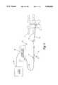
- FIG. 1is a schematic representation of the endoscopic device for direct spinal visualization of the present invention.
- FIG. 2is an enlarged view of the endoscopic device of FIG. 1.
- FIG. 3is a side cross-sectional view of the tip deflection mechanism used in connection with the endoscopic device of FIG. 2.
- FIG. 4is an enlarged view of the deflecting tip of the catheter for the endoscope shown in FIG. 3, as viewed in the region labeled 4 of that figure.
- FIG. 5is an end cross-sectional view of the introducer catheter used in connection with the endoscopic device shown in FIG. 3 taken along line 5--5 as viewed in the direction of the arrows.
- FIG. 6is an enlarged view of the introduction of the deflection wire into the introducer catheter, as shown in the detail region labeled 6 in FIG. 3.
- FIG. 7is a side cross-sectional view of the optical fiber adjustment means shown in FIG. 2 for adjusting the position of the fiber-optic bundle with respect to the introducer catheter.
- the present inventioncontemplates a system for direct visualization of the spine and epidural space that is adapted for percutaneous introduction into the epidural and/or intra-discal spaces.
- the systemincludes a disposable flexible catheter, a fiber-optic bundle disposed within the catheter, means for connecting the bundle to a light source and camera, means for adjustably connecting the bundle to the proximal end of the catheter, and means for controllably deflecting the tip of the catheter to vary the viewing angle of the fiber-optic bundle in the spinal space. Deflection of the viewing tip also provides means for controllably steering the catheter through tight regions in the spinal space.
- the inventive systemincludes a small diameter disposable flexible catheter having a first channel extending along the entire length of the catheter opening at the distal end of the catheter at a deflectable or bendable tip.
- a fiber-optic bundlewhich includes coaxially disposed imaging fibers and light fibers, is slidably received within the first channel.
- Meansare provided for engaging the imaging fibers to a camera and the light fibers to a light source.
- the first channelalso serves as an irrigation channel in addition to supporting the fiber-optic bundle.
- Meansare also provided for fluidly engaging the first channel to a source of irrigation fluid.
- this connecting meansincludes a clamp for clamping the fiber-optic bundle and means for adjusting the length distance between the distal end of the catheter and the clamp means. More particularly, the connecting means contemplates a first housing attached to the proximal end of the catheter and a second housing connected to the clamp. A bore passes through both housings for slidably receiving the fiber-optic bundle therethrough.
- a threaded post on the second housing and a mating threaded bore in the first housingare adjustably threaded together to adjust the length distance between the distal end of the catheter and the clamp.
- the two housingsmove closer together thereby reducing the distance between the catheter distal end and the clamp for the fiber-optic bundle.
- the viewing end of the bundlemoves toward the end of the catheter.
- unthreading the post from the boreincreases the distance between catheter distal end and clamp, thereby causing the fiber-optic bundle to, in effect, recede within the catheter.
- Radio-opaque markingscan be made at the distal ends of the catheter and the fiber-optic bundle to permit radiographic verification of the relative position of the distal end of the bundle to the distal end of the catheter.
- meansare also provided for rotating the fiber-optic bundle relative to the catheter.
- This rotation meansincludes a third housing attached to the clamp which is rotatably mounted on the second housing to permit relative rotation between the housings.
- the systemalso includes means for controllably deflecting the tip of the catheter when the distal end is in the epidural space.
- This tip deflection meansincludes a deflection wire having a first end and a second end in which a first portion of the wire is adjacent the first end disposed outside the catheter and a second portion of the wire between the first portion and the second end extends through the catheter. The second end of the deflection wire is secured to the catheter at the distal end.
- the wireis affixed to a stainless steel ring which is affixed to the end opening of a tube mounted at the tip of the catheter.
- the tip deflection meansfurther includes means for moving the catheter in a first direction oriented toward the distal end of the catheter and means for restraining the first end or the deflection wire against movement in the first direction as the catheter is moved in that direction.
- the means for restraining the deflection wireincludes an elongated housing defining a cavity therein, the housing having openings at its ends for slidably receiving the catheter therethrough.
- the first end of the deflection wireis connected to a sleeve within the cavity which is slidably disposed about the catheter.
- the housingincludes a flange in the cavity which is a stop surface for restraining movement or the sleeve in the first direction.
- the tip deflecting meansIn the operation of the tip deflecting means, movement of the catheter in the first direction carries the deflection wire until the sleeve contacts the stop surface of the flange. As the catheter is moved further in the first direction, the wire is put into tension between the restrained first end and the second end affixed to the catheter distal end. This tension operates to pull the portion of the catheter back to which the deflection wire is attached, thereby bending the catheter tip in the direction of the attachment of the deflection wire.
- the means for moving the catheterincludes means for limiting movement of the catheter in the first direction relative to the deflection wire sleeve once the sleeve has contacted the stop surface. Limiting the catheter movement in the first direction controls or limits the amount of deflection of the tip.
- This means for limiting movementcan include a first stop connected to the catheter which is slidable within the cavity and a pin affixed to the housing and projecting into the cavity between the first stop and the sleeve. Thus, the first stop will contact the pin when the catheter is moved in the first direction.
- the first stopis situated at a predetermined distance from the pin when the sleeve contacts the flange stop surface such that movement of the catheter and the first stop through the predetermined distance will result in a controlled tip deflection, which can range from 0° to about 90°.
- a second stopmay also be included which is connected to the catheter and slidable within the cavity between the pin and the sleeve, whereby the second stop contacts the pin when the catheter is moved in a second direction opposite the first direction.
- the means for moving the catheteralso includes means for rotating the catheter with the tip deflected so the fiber-optic bundle can be swept through a conical viewing field within the epidural space.
- the cathetercan include a send-circular first channel through which the fiber-optic bundle extends.
- the diameter of the bundlecan be slightly less than the radius of the semi-circular channel to support the bundle without excessive movement.
- a second channelcan also be provided for receiving the deflection wire.
- the second channelincludes a slot opening into the second channel through which the deflection wire extends.
- the second channelterminates short of the distal end of the catheter and the catheter has a reduced outer dimension from the end of the second channel to the distal end of the catheter.
- the deflection wirethen projects from the end of the second channel adjacent the reduced outer dimension to its securement on the outer tube.
- a third channelmay be provided for introduction of working instruments or a laser fiber.
- the inventionalso contemplates a method for direct visualization of the spine and epidural space.
- the methoduses an endoscope formed of a flexible catheter with a fiber-optic bundle slidably disposed therein, catheter having a deflectable tip and the fiber-optic bundle being connected to a light source and camera.
- the catheteris percutaneously inserted into the body and placed within the epidural space in a region to be observed.
- the fiber-optic bundleis kept retracted within the catheter until the catheter tip reaches the region.
- the fiber-optic bundleis then extended relative to the catheter until the viewing end of the bundle is adjacent the end of the catheter, which position is radiographically verified.
- the methodfurther contemplates steps of deflecting the catheter tip to vary the viewing angle of the viewing end of the fiber-optic bundle within the epidural space, rotating the catheter with the tip deflected, and rotating the fiber-optic bundle relative to the catheter, all in order to vary the viewing angle and view orientation of the image transmitted through the fiber-optic bundle.
- steps of deflecting the catheter tip to vary the viewing angle of the viewing end of the fiber-optic bundle within the epidural spacerotating the catheter with the tip deflected, and rotating the fiber-optic bundle relative to the catheter, all in order to vary the viewing angle and view orientation of the image transmitted through the fiber-optic bundle.
- Each of these stepsmay occur relatively simultaneously or in sequence as required to provide full visualization of the epidural space.
- the catheteris adapted to accommodate a fiber-optic bundle that is either reusable or disposable.
- a further objectcontemplates an endoscope for direct spinal visualization which has a small diameter for percutaneous insertion, yet still includes the capability to vary the viewing field within the epidural space.
- This objectis achieved by the catheter including means for deflecting the tip with the fiber-optic bundle within, as well as for rotating the catheter with the tip deflected and rotating the fiber-optic bundle relative to the catheter.
- a further objectis to provide these features for varying the viewing field in a device that includes few moving parts and that is easily assembled.
- all of the components providing these featurescan be disposable.
- the spinal visualization system 10 of the present inventionis depicted.
- the visualization system 10is an endoscopic system which includes a delivery catheter 12 having a deflecting viewing tip 13.
- the cathetercan be introduced into the body using a separate introducer cannula set known in the art.
- the delivery catheter 12can be introduced with the deflecting tip 13 adjacent the spinal column or specific vertebra of the spine.
- the delivery catheter 12 and tip 13constitute an endoscope for direct vision of the spine.
- a hand piece 15is provided for deflecting the tip and for rotating the viewing tip 13 to provide a full viewing field of the spine.
- Irrigation port means 19is included to provide irrigation to the delivery catheter 12. Irrigation fluid can be introduced through the tip 13 into the spinal region to clear obstructions in the viewing field.
- a fiber-optic bundle 20passes through the delivery catheter 12 to form the vision component of the flexible endoscope.
- An optic bundle adjustment means 21is provided which orients the viewing tip of the fiber-optic bundle 20 with respect to the deflecting tip 13 of the delivery catheter.
- the proximal end of the fiber-optic bundle 20is engaged in a conventional manner to a camera and light source 23 which can be of known construction.
- a video screen 24 connected to the camera 23televises the images of the spine for direct viewing by medical personnel.
- the video screen 24, camera and light source 23 and fiber-optic bundle 20can be of a known commercially available design.
- the camera and light sourcecan be the Model 2000 system provided by Citation Medical Co.
- the fiber-optic bundlecan be custom configured using known technology to account for the need of specific applications of the system.
- the delivery catheter 12can be inserted percutaneously into the patient using a cannula, trocar or similar instrument.
- the flexible nature of the catheterallows the viewing tip to be guided through or around the vertebrae to the affected region.
- the viewing tip 13can then be orient for a better view or it can be manipulated throughout the region.
- the construction of the visualization system 10, and particularly the delivery catheter 12,permits potential reuse of the fiber-optic bundle 20 which can be easily and readily inserted into the catheter to a proper viewing position.
- the bundle 20may itself be disposable and provided together with the catheter in disposable sterile packaging.
- the delivery catheter 12is shown with the viewing tip 13 also shown in its deflected position 13' which is oriented at an angle of approximately 45° to the undeflected position of the tip (at least in one specific embodiment).
- the hand piece 15includes a plunger 26 which operates within a deflection control mechanism 27.
- the plunger 26can be depressed in the direction of the arrow D to a second position 26' which corresponds to the deflected position 13' of the viewing tip.
- the plunger 26can also be rotated in the direction of the circular arrow R to thereby rotate the delivery catheter 12 and viewing tip 13 in a similar direction.
- the handpiece 15provides for a wide viewing field with the fiber-optic bundle contained within the delivery catheter 12.
- the illustrated tip deflectionpermits the viewing tip 13 to be swept through a cone angle of about 45°. It is understood, or course, that this specific embodiment is not intended to limit the tip deflection capability of the present invention. More specifically, the hand piece 15 can be configured to produce viewing tip deflections or cone angles which can vary between 0° and about 90°.
- the delivery catheter 12extends through the hand piece 15 to engage a tubing junction 31.
- the tubing junction 31forms part of the irrigation port means 19.
- An irrigation tube 29, which preferable terminates at its proximal end in a Luer Loc® connection 30,can be integral with the tubing junction 31.
- a second catheter tube 17is also connected to the junction 31.
- the second catheter tube 17is attached to the fiber-optic adjustment means 21 and accommodates the fiber-optic bundle 20 passing therethrough.
- the tubing junction 31marries tube 17 initially carrying the fiber-optic bundle 20 to a means for providing irrigation fluid 19 which combine to pass both irrigation fluid and fiber-optic bundle through the catheter 12 to the viewing tip 13.
- the hand piece 15includes the plunger 26 which comprises a plunger handle 35 and a stiffening sheath 37 affixed to and supported by the handle 35.
- a guide tube 39projects from the forward end of the plunger handle 35.
- the stiffening sheath 37 and guide tube 39define a bore 40 through which the flexible delivery catheter 12 is inserted.
- the stiffening sheath 37projects distally from the plunger handle 35 and the bore 40 is sized so that a very close fit is provided around the catheter 12.
- the catheteris fixed to the stiffening sheath 37 or guide tube 39, such as by epoxy or welding, so that the catheter 12 moves with the plunger handle 35.
- a deflection control sleeve 55Slidably disposed between the housing 42 and the stiffening sheath 37 is a deflection control sleeve 55.
- the deflection wire 57is affixed to the control sleeve 55 at a proximal attachment portion 58 of the wire.
- the attachment portion 58 of wire 57is embedded in the control sleeve 55, although other means of affixing the proximal end of the wire to the sleeve is contemplated.
- the deflection wire 57extends through the remaining length of the catheter 12 and its distal end is fastened to the catheter at the viewing tip 13 in a manner to be discussed herein.
- a flange 59is provided in the end housing 44 to act as a stop surface for movement of the control sleeve 55 in the direction D.
- deflection of the tip 13is accomplished by way of the relative movement of the catheter 12 with respect to the deflection wire 57. More specifically, as the plunger 26 is depressed into the cavity 47 of housing 42, the catheter 12, which is fixed to the plunger, also moves and extends further beyond end housing 44. As the catheter 12 moves, the deflection wire 57, which is affixed to the tip 13 of the catheter, also moves until the control sleeve 55 contacts the flange 59. At this point, further movement of the catheter 12 relative to the now restrained deflection wire 57 creates tension in the deflection wire which tries to pull the tip 13 back as the catheter 12 continues to advance.
- the tip 13will continue to bend until the left stop 49 contacts the pin 52 at which point the tip as at its maximum deflected position 13'. It is understood that once the control sleeve 55 contacts the flange 59, the deflection wire 57 will no longer translate. Instead, the tension in the deflection wire 57 will cause the wire to pull the tip 13 back toward the control sleeve 55.
- the tipcan be returned from its deflected position 13' to its undeflected position by pulling the plunger 35 back in the opposite direction, which gradually decreases the tension in the deflection wire 55.
- the natural resilience of the catheter material, as well as the resilience of the deflection wire,will then cause the catheter to straighten. This same resilience may tend to cause the catheter to straighten without pulling back on plunger 35.
- the plunger 35may be biased to the neutral undeflected tip position by way of a spring situated, for example, between the right stop 50 and the flange 59.
- rotation of the tip 13can be achieved by rotating plunger 35 in the direction of arrow R.
- the deflection wire 57also rotates with the tip so simultaneous deflection and rotation of the tip is permitted.
- the control sleeve 55will also rotate as it is pulled by the deflection wire.
- the control sleeve 55 and sheath 37may include mating radial splines (not shown) so rotation of the plunger is directly transmitted to the control sleeve.
- the tip 13includes an outer end tube 80 which is affixed to the delivery catheter at joint 81.
- the end tube 80has an open end 83 to provide an opening for viewing through the fiber-optic bundle 20.
- a stainless steel ring 85is engaged within the end tube 80, preferably immediately adjacent the open end 83.
- the ring 85can either be epoxied to the tube or the tube 80 can be shrunk onto the ring to hold it firmly in position.
- the deflection wire 57is then fixed to the ring 85 at a fixation point 87, preferably at the top of the ring, by welding or other fixation.
- the present inventioncontemplates a completely disposable catheter arrangement for use with either a reusable or no-reusable disposable fiber-optic bundle 20.
- the construction of the delivery catheter 12is shown in the cross-sectional view of FIG. 5.
- the catheterincludes a body 62 which is preferably made of standard grade medical plastic, such as polyurethane, extruded into the appropriate configuration.
- the bodyin one specific embodiment has an outer diameter of 2.0-2.75 mm to facilitate movement in the tight quarters of the epidural space and to keep the puncture site diameter as small as possible.
- the present inventioncontemplates a smaller catheter diameter, about 1.0 mm, with the catheter features (such as channel dimensions) being correspondingly reduced in size.
- the length of the catheter 12 from tip 13 to tubing junction 31is about 840.0 mm (33 inches).
- the bodydefines an irrigation channel 64 which is preferably semi-circular in shape and occupies the lower half of the circular body 62. Disposed within the irrigation channel 64 is the fiber-optic bundle 20.
- the diameter of the fiber-optic bundleis slightly smaller than the lumen of the semi-circular irrigation channel 64 which in one specific embodiment is 0.89-1.35 mm (corresponding to a catheter outer diameter of 2.0-2.75 mm).
- the space 65 around the fiber-optic bundle 20 in the irrigation channel 64can be used for flowing irrigation fluid through the catheter to the viewing site.
- the fiber-optic bundle 20 of one specific embodimentincludes an image bundle 70 surrounded by a number of light fiber bundles 72.
- the fiber-optic bundle 20can be surrounded by a sheath as required to avoid damage to the fiber-optic components.
- the diameter of the bundlepreferably has an outer diameter of 0.8-1.2 mm.
- the image bundle 70preferably has an outer diameter of between 0.35 and 0.5 mm and a resolution of 6,000-12,000 pixels.
- the catheter bodyalso includes a guide wire channel 66 through which the guide wire 57 extends.
- the guide wire channel 57has a diameter of 0.58-0.76 mm (corresponding to a catheter outer diameter of 2.0-2.75 mm).
- a pair of stiffener channels 68are also provided in the catheter body 62.
- a pair of stiffening rods(not shown) can be readily inserted through the channel 68 to add rigidity to the delivery catheter 12.
- the stiffener channelscan terminate short of the distal end of the catheter so that unnecessary stiffness is not added at the deflecting tip.
- the deflection wire 57itself can include a stiffening sheath around the wire.
- the catheter body 62includes a cut-back 74 at the deflection wire channel half of the body. More particularly, a truncated outer wall 76 surrounding the irrigation channel 64 is provided by longitudinally slicing the catheter body 62 at a cut line 77 shown in FIG. 5. The catheter body is cut back from the open end 83 of the outer end tubing 80 to the cut-back portion 74 to leave the guide wire 57 exposed.
- This cut-back portion, or more particularly the length of the truncated outer wall 76corresponds generally to the length of the tip that will be deflected upon actuation of the hand piece assembly 15.
- the tip lengthis preferably between 1.0-2.5 cm. In one specific embodiment, this tip length is 1 cm.
- the viewing end 73 of the fiber-optic bundle 20is disposed just inside the open end 83 of the outer end tubing 80.
- the viewing end 73is preferably shielded in this manner so that it does not contact the body tissue as the catheter is introduced into the spinal region.
- the deflection wire channel 66includes a slot 90 through the outer wall of the catheter body 62.
- the deflection wire 57then passes through that slot into the deflection wire channel 66.
- the deflection wire 57include a clearance bend 92 which allows the wire 57 to clear not only the catheter body 62 but also the stiffening sheath 37 (FIG. 3).
- the attached portion 58 of the wireextends from the clearance bend 92 and is affixed to the control sleeve 55 as previously discussed.
- the slot 90is long enough to permit the catheter to translate relative to the clearance bend 92 for the full deflection capability of the viewing tip 13, without the deflection wire 57 contacting the ends of the slot 90.
- the slot 90can be narrow so that rotation of the catheter 12 due to rotation of the plunger 35 reacts to push the wire, and hence the control sleeve 55, in the direction of rotation.
- an optical bundle adjustment means 21is provided.
- the bundle 20is preferably threaded through the adjustment means 21, tube 17, junction 31 and into irrigation channel 64 of catheter 12 until it is at the viewing tip 13.
- the adjustment means 21allows the operator to vary the position of the viewing end 73 of the bundle 20 with respect to the open end 83 of the outer end tubing 80 at the tip 13.
- the bundleis preferably pulled back front the tip while irrigation fluid is used to keep the catheter clear of tissue.
- the bundle 20 and particularly viewing end 73should be close to the open end 83 for optimum viewing.
- manipulation of the fiber-optic bundle 20may be required to keep the viewing end disposed within the outer end tubing 80, or to provide a more optimum position for the viewing end for a wider field of vision.
- the optic bundle adjustment means 21includes a locking base 94 and a conical locking nut 95.
- the locking nut 95is threaded onto a threaded post 96.
- a bore 97is defined by the base 94 and threaded post 96 through which fiber-optic bundle 20 extends.
- the threaded post 96is preferably resilient or is slotted so that it can be compressed onto the outer surface of the optic bundle 20 to grip the bundle. As the conical locking nut 95 is threaded onto the post, it forces the walls of the post to trap the fiber-optic bundle 20.
- a rotator body 98is also provided to which the locking base 94 is fixed, such as by a threaded connection 99.
- the rotator body 98includes a swivel flange 100 and a bore 101 extending therethrough. Naturally, the fiber-optic bundle 20 extends through this bore 101.
- the swivel flange 100is snapped into a length adjustment body 103. More particularly, the length adjustment body 103 includes a corresponding swivel flange 105 which traps the flange 100 of rotator body 98 while permitting relative rotation between the two bodies.
- the two flanges 100 and 105can be engaged by simply resiliently pressing the two bodies together.
- the length adjustment body 103further includes a bore 104 to receive the fiber-optic bundle 20 therethrough and a threaded adjustment post 106 extending from its distal end.
- the threaded adjustment post 106is adapted to engage an adjustment bore 110 of a catheter engagement body 108.
- the engagement body 108includes a bore 109 therethrough to receive the fiber-optic bundle 20.
- a mounting insert 111is provided which fixes the tube 17 to the catheter engagement body 108. As shown in FIG. 2, the tube 17 mates with the tubing junction 31, which then mates with the delivery catheter 12. It should then thus be understood that any movement of the tube 17 is directly translated to an identically corresponding movement of delivery catheter 12.
- the fiber-optic bundle 20passes freely through certain components of the optic bundle adjustment means 21, any movement of the these components does not result in corresponding movement of the optical bundle 20.
- the fiber-optic bundle 20is fastened to the locking base 94 by way of the locking nut 95 and resilient threaded post 96, as previously discussed.
- the relative position of the optic bundle 20 to the delivery catheter 12can be adjusted by twisting the length adjustment body 103 relative to the catheter engagement body 108.
- the adjustment post 106is threaded more deeply into the adjustment bore 110 of catheter engagement body 108, the effective length or the catheter is shortened, while the fiber-optic bundle maintains its given length.
- the viewing end 73 of the bundle 20moves closer to the open end 83 of the viewing tip 13.
- the adjustment post 106is threaded out of the bore 110, the effective length of the catheter is increased. With this motion, the viewing end 73 of the optical fiber bundle 20 effectively recedes within the viewing tip 13.
- the optical fiber bundle 20can be rotated by twisting the rotator body 98 relative to the length adjustment body 103 and catheter engagement body 108. As the rotator body 98 is turned, the swivel flanges 100 and 105 cooperate so that no rotational movement is transmitted into the other components of the optical bundle adjustment means 21.
- the position and orientation of the viewing end 73 of the optical fiber bundle 20can be verified radiographically by viewing the radio-opaque markings 115 at the end of the fiber-optic bundle 20.
- the ring 85is formed of a radio-opaque material, such as stainless steel, or includes a radio-opaque marking similar to marking 115.
- the catheter body 62can include separate channels for irrigation fluid and for housing the fiber-optic bundle 20.
- a modification to the deflection control mechanism 27can eliminate the left stop body 49 and instead rely upon the right stop body 50 contacting the control sleeve 55 to limit the relative movement between the catheter 12 and deflection wire 57. By moving the pin 52 and right stop body 50 closer to the control sleeve movement of the catheter can be controlled with fewer components.
Landscapes
- Health & Medical Sciences (AREA)
- Life Sciences & Earth Sciences (AREA)
- Surgery (AREA)
- Biophysics (AREA)
- Biomedical Technology (AREA)
- Veterinary Medicine (AREA)
- Public Health (AREA)
- General Health & Medical Sciences (AREA)
- Pathology (AREA)
- Animal Behavior & Ethology (AREA)
- Molecular Biology (AREA)
- Engineering & Computer Science (AREA)
- Physics & Mathematics (AREA)
- Heart & Thoracic Surgery (AREA)
- Medical Informatics (AREA)
- Radiology & Medical Imaging (AREA)
- Optics & Photonics (AREA)
- Nuclear Medicine, Radiotherapy & Molecular Imaging (AREA)
- Neurology (AREA)
- Orthopedic Medicine & Surgery (AREA)
- Hematology (AREA)
- Media Introduction/Drainage Providing Device (AREA)
- Endoscopes (AREA)
Abstract
Description
Claims (38)
Priority Applications (18)
| Application Number | Priority Date | Filing Date | Title |
|---|---|---|---|
| US07/865,349US5396880A (en) | 1992-04-08 | 1992-04-08 | Endoscope for direct visualization of the spine and epidural space |
| AR93324631AAR248075A1 (en) | 1992-04-08 | 1993-03-31 | Endoscope for direct visualization of the spine and epidural space. |
| AU40472/93AAU661774B2 (en) | 1992-04-08 | 1993-04-07 | Endoscope for direct visualization of the spine and epidural space |
| BR9306213ABR9306213A (en) | 1992-04-08 | 1993-04-07 | Endoscope for direct visualization of the spine and epidural space |
| PCT/US1993/003217WO1993020742A1 (en) | 1992-04-08 | 1993-04-07 | Endoscope for direct visualization of the spine and epidural space |
| AT93911597TATE172368T1 (en) | 1992-04-08 | 1993-04-07 | ENDOSCOPE FOR VISIBILITY OF THE SPINAL AND EPIDURAL SPACE |
| DE69321723TDE69321723T2 (en) | 1992-04-08 | 1993-04-07 | ENDOSCOPE TO VISIBLE THE SPINAL AND EPIDURAL SPACE |
| EP93911597AEP0644736B1 (en) | 1992-04-08 | 1993-04-07 | Endoscope for direct visualization of the spine and epidural space |
| TR00305/93ATR27506A (en) | 1992-04-08 | 1993-04-07 | Endoscope for direct viewing of the spine and epidural cavity. |
| CA002117781ACA2117781A1 (en) | 1992-04-08 | 1993-04-07 | Endoscope for direct visualization of the spine and epidural space |
| JP5518427AJPH07506270A (en) | 1992-04-08 | 1993-04-07 | Endoscopy for direct visualization of the spinal cord and epidural space |
| KR1019940703528AKR0151437B1 (en) | 1992-04-08 | 1993-04-07 | Endoscopy for direct visualization of the spine and epidural space |
| CN93105729ACN1105843A (en) | 1992-04-08 | 1993-04-08 | Endoscope for direct visualization of the spine and epidural space |
| ZA932546AZA932546B (en) | 1992-04-08 | 1993-04-08 | Endoscope for direct visualization of the spine and epidural space |
| TW082103487ATW268890B (en) | 1992-04-08 | 1993-05-04 | |
| KR1019940703528AKR950700700A (en) | 1992-04-08 | 1994-10-06 | Endoscope for direct visualization of the spine and epidural space |
| FI944673AFI944673A7 (en) | 1992-04-08 | 1994-10-06 | Endoscope for direct visualization of the spine and epidural space |
| NO943788ANO943788L (en) | 1992-04-08 | 1994-10-07 | Endoscope for direct visualization of the spine and epidural space |
Applications Claiming Priority (1)
| Application Number | Priority Date | Filing Date | Title |
|---|---|---|---|
| US07/865,349US5396880A (en) | 1992-04-08 | 1992-04-08 | Endoscope for direct visualization of the spine and epidural space |
Publications (1)
| Publication Number | Publication Date |
|---|---|
| US5396880Atrue US5396880A (en) | 1995-03-14 |
Family
ID=25345308
Family Applications (1)
| Application Number | Title | Priority Date | Filing Date |
|---|---|---|---|
| US07/865,349Expired - LifetimeUS5396880A (en) | 1992-04-08 | 1992-04-08 | Endoscope for direct visualization of the spine and epidural space |
Country Status (17)
| Country | Link |
|---|---|
| US (1) | US5396880A (en) |
| EP (1) | EP0644736B1 (en) |
| JP (1) | JPH07506270A (en) |
| KR (2) | KR0151437B1 (en) |
| CN (1) | CN1105843A (en) |
| AR (1) | AR248075A1 (en) |
| AT (1) | ATE172368T1 (en) |
| AU (1) | AU661774B2 (en) |
| BR (1) | BR9306213A (en) |
| CA (1) | CA2117781A1 (en) |
| DE (1) | DE69321723T2 (en) |
| FI (1) | FI944673A7 (en) |
| NO (1) | NO943788L (en) |
| TR (1) | TR27506A (en) |
| TW (1) | TW268890B (en) |
| WO (1) | WO1993020742A1 (en) |
| ZA (1) | ZA932546B (en) |
Cited By (167)
| Publication number | Priority date | Publication date | Assignee | Title |
|---|---|---|---|---|
| WO1996027321A3 (en)* | 1995-02-27 | 1996-12-27 | Michelson Gary K | Improved methods and instrumentation for the surgical correction of human thoracic and lumbar spinal disease from the lateral aspect of the spine |
| US5792044A (en)* | 1996-03-22 | 1998-08-11 | Danek Medical, Inc. | Devices and methods for percutaneous surgery |
| US5797909A (en) | 1988-06-13 | 1998-08-25 | Michelson; Gary Karlin | Apparatus for inserting spinal implants |
| USD398986S (en) | 1996-01-16 | 1998-09-29 | Catheter Imaging Systems, Inc. | Handle interface for steerable catheter |
| US5833605A (en)* | 1997-03-28 | 1998-11-10 | Shah; Ajit | Apparatus for vascular mapping and methods of use |
| US5846221A (en) | 1996-02-09 | 1998-12-08 | Catheter Imaging Systems, Inc. | Steerable catheter having disposable module and sterilizable handle and method of connecting same |
| US5857996A (en) | 1992-07-06 | 1999-01-12 | Catheter Imaging Systems | Method of epidermal surgery |
| WO1999002214A1 (en)* | 1997-07-09 | 1999-01-21 | Tegementa, L.L.C. | Interbody device and method for treatment of osteoporotic vertebral collapse |
| USD405881S (en) | 1996-01-16 | 1999-02-16 | Catheter Imaging Systems, Inc. | Handle for steerable catheter |
| WO1999045994A1 (en)* | 1998-03-11 | 1999-09-16 | Dalia Beyar | Remote control catheterization |
| US6007531A (en) | 1995-11-21 | 1999-12-28 | Catheter Imaging Systems, Inc. | Steerable catheter having disposable module and sterilizable handle and method of connecting same |
| US6013025A (en)* | 1996-07-11 | 2000-01-11 | Micro Medical Devices, Inc. | Integrated illumination and imaging system |
| US6030360A (en)* | 1996-12-30 | 2000-02-29 | Biggs; Robert C. | Steerable catheter |
| US6035229A (en)* | 1994-07-14 | 2000-03-07 | Washington Research Foundation | Method and apparatus for detecting Barrett's metaplasia of the esophagus |
| US6096038A (en) | 1988-06-13 | 2000-08-01 | Michelson; Gary Karlin | Apparatus for inserting spinal implants |
| US6120502A (en) | 1988-06-13 | 2000-09-19 | Michelson; Gary Karlin | Apparatus and method for the delivery of electrical current for interbody spinal arthrodesis |
| US6123705A (en) | 1988-06-13 | 2000-09-26 | Sdgi Holdings, Inc. | Interbody spinal fusion implants |
| US6126660A (en)* | 1998-07-29 | 2000-10-03 | Sofamor Danek Holdings, Inc. | Spinal compression and distraction devices and surgical methods |
| US6129662A (en)* | 1996-06-03 | 2000-10-10 | Cogent Light Technologies, Inc. | Surgical tool with surgical field illuminator |
| US6146355A (en)* | 1996-12-30 | 2000-11-14 | Myelotec, Inc. | Steerable catheter |
| US6152871A (en)* | 1996-03-22 | 2000-11-28 | Sdgi Holdings, Inc. | Apparatus for percutaneous surgery |
| US6162170A (en)* | 1996-03-22 | 2000-12-19 | Sdgi Holdings, Inc. | Devices and methods for percutaneous surgery |
| US6210412B1 (en) | 1988-06-13 | 2001-04-03 | Gary Karlin Michelson | Method for inserting frusto-conical interbody spinal fusion implants |
| US6213974B1 (en) | 1996-12-30 | 2001-04-10 | Visionary Biomedical, Inc. | Steerable catheter having segmented tip and one-piece inlet housing, and method of fabricating same |
| US20020045855A1 (en)* | 1997-02-10 | 2002-04-18 | Essex Technology, Inc. | Rotate to advance catheterization system |
| US6419626B1 (en) | 1998-08-12 | 2002-07-16 | Inbae Yoon | Surgical instrument endoscope with CMOS image sensor and physical parameter sensor |
| US20020138144A1 (en)* | 1995-02-17 | 2002-09-26 | Michelson Gary Karlin | Threaded frusto-conical interbody spinal fusion implants |
| US20020198532A1 (en)* | 1993-06-10 | 2002-12-26 | Sofamor Danek Holdings, Inc. | Apparatus and method of inserting spinal implants |
| US20030073998A1 (en)* | 2000-08-01 | 2003-04-17 | Endius Incorporated | Method of securing vertebrae |
| US6558390B2 (en) | 2000-02-16 | 2003-05-06 | Axiamed, Inc. | Methods and apparatus for performing therapeutic procedures in the spine |
| US6558386B1 (en) | 2000-02-16 | 2003-05-06 | Trans1 Inc. | Axial spinal implant and method and apparatus for implanting an axial spinal implant within the vertebrae of the spine |
| US6572543B1 (en)* | 1996-06-26 | 2003-06-03 | Medtronic, Inc | Sensor, method of sensor implant and system for treatment of respiratory disorders |
| US6574401B2 (en)* | 1999-03-30 | 2003-06-03 | Ceramoptec Industries, Inc. | Optical fiber-handpiece combination for medical laser treatments |
| US6575979B1 (en) | 2000-02-16 | 2003-06-10 | Axiamed, Inc. | Method and apparatus for providing posterior or anterior trans-sacral access to spinal vertebrae |
| US20030158553A1 (en)* | 1988-06-13 | 2003-08-21 | Michelson Gary Karlin | Instrumentation for the surgical correction of spinal disease |
| US6679833B2 (en) | 1996-03-22 | 2004-01-20 | Sdgi Holdings, Inc. | Devices and methods for percutaneous surgery |
| US6740090B1 (en) | 2000-02-16 | 2004-05-25 | Trans1 Inc. | Methods and apparatus for forming shaped axial bores through spinal vertebrae |
| US6758849B1 (en) | 1995-02-17 | 2004-07-06 | Sdgi Holdings, Inc. | Interbody spinal fusion implants |
| US6770074B2 (en) | 1988-06-13 | 2004-08-03 | Gary Karlin Michelson | Apparatus for use in inserting spinal implants |
| US20040176763A1 (en)* | 1996-03-22 | 2004-09-09 | Foley Kevin T. | Methods for percutaneous surgery |
| US20040186346A1 (en)* | 1996-03-22 | 2004-09-23 | Smith Maurice M. | Devices and methods for percutaneous surgery |
| US20040254583A1 (en)* | 2000-10-24 | 2004-12-16 | Mckay William F. | Osteogenic packing device and method |
| US6899716B2 (en) | 2000-02-16 | 2005-05-31 | Trans1, Inc. | Method and apparatus for spinal augmentation |
| US20050137612A1 (en)* | 2003-10-23 | 2005-06-23 | Assell Robert L. | Access assembly for guiding instrumentation through soft tissue to a point on the spine |
| US20050165489A1 (en)* | 1995-06-07 | 2005-07-28 | Michelson Gary K. | Frusto-conical spinal implant |
| US20050177101A1 (en)* | 2004-02-06 | 2005-08-11 | Bruce Wilson | Method and apparatus for guide catheter positioning |
| US20050251108A1 (en)* | 1999-09-27 | 2005-11-10 | Essex Technology, Inc. | Rotate-to-advance catheterization system |
| US20050261695A1 (en)* | 2000-02-16 | 2005-11-24 | Cragg Andrew H | Method and apparatus for spinal distraction and fusion |
| US20060030753A1 (en)* | 2004-08-09 | 2006-02-09 | Scimed Life Systems, Inc. | Fiber optic imaging catheter |
| US20060084992A1 (en)* | 1988-06-13 | 2006-04-20 | Michelson Gary K | Tubular member having a passage and opposed bone contacting extensions |
| US20060089633A1 (en)* | 2004-10-15 | 2006-04-27 | Baxano, Inc. | Devices and methods for tissue access |
| US20060094976A1 (en)* | 2004-10-15 | 2006-05-04 | Baxano, Inc. | Devices and methods for selective surgical removal of tissue |
| US20060122458A1 (en)* | 2004-10-15 | 2006-06-08 | Baxano, Inc. | Devices and methods for tissue access |
| US20060167342A1 (en)* | 2004-12-07 | 2006-07-27 | Konstantin Bob | Endoscope having a rotatable distal endoscope head |
| US20060173242A1 (en)* | 2004-12-13 | 2006-08-03 | Acmi Corporation | Hermetic endoscope assemblage |
| US20060178691A1 (en)* | 2004-02-26 | 2006-08-10 | Binmoeller Kenneth F | Methods and devices to curb appetite and/or reduce food intake |
| US20060206002A1 (en)* | 2005-02-28 | 2006-09-14 | Frassica James J | Rotate-to-advance catheterization system |
| US20060241648A1 (en)* | 2005-02-04 | 2006-10-26 | Bleich Jeffery L | Methods and apparatus for tissue modification |
| US20060241350A1 (en)* | 2005-04-22 | 2006-10-26 | Sdgi Holdings, Inc. | Instruments and methods for selective tissue retraction through a retractor sleeve |
| US20060258951A1 (en)* | 2005-05-16 | 2006-11-16 | Baxano, Inc. | Spinal Access and Neural Localization |
| US20060264919A1 (en)* | 2005-04-22 | 2006-11-23 | Polydiagnost Gmbh | Endoscope with a flexible probe |
| US20060264957A1 (en)* | 2000-02-16 | 2006-11-23 | Trans1, Inc. | Apparatus for performing a discectomy through a trans-sacral axial bore within the vertebrae of the spine |
| US20070005041A1 (en)* | 2005-05-04 | 2007-01-04 | Frassica James J | Rotate-to-advance catheterization system |
| US20070055260A1 (en)* | 2003-06-10 | 2007-03-08 | Cragg Andrew H | Method and apparatus for providing posterior or anterior trans-sacral access to spinal vertebrae |
| US20070066977A1 (en)* | 2004-10-22 | 2007-03-22 | Assell Robert L | Exchange system for axial spinal procedures |
| US20070213734A1 (en)* | 2006-03-13 | 2007-09-13 | Bleich Jeffery L | Tissue modification barrier devices and methods |
| US20070213733A1 (en)* | 2004-10-15 | 2007-09-13 | Bleich Jeffery L | Mechanical tissue modification devices and methods |
| US20070213735A1 (en)* | 2004-10-15 | 2007-09-13 | Vahid Saadat | Powered tissue modification devices and methods |
| US20070233260A1 (en)* | 2000-02-16 | 2007-10-04 | Trans1 Inc. | Articulating spinal implant |
| US7291149B1 (en) | 1995-06-07 | 2007-11-06 | Warsaw Orthopedic, Inc. | Method for inserting interbody spinal fusion implants |
| US20070260252A1 (en)* | 2006-05-04 | 2007-11-08 | Baxano, Inc. | Tissue Removal with at Least Partially Flexible Devices |
| US20070293885A1 (en)* | 2004-02-26 | 2007-12-20 | Binmoeller Kenneth F | Methods and devices to curb appetite and/or to reduce food intake |
| US20080015544A1 (en)* | 2006-04-21 | 2008-01-17 | Entellus Medical, Inc. | Method for accessing a sinus cavity and related anatomical features |
| US20080033465A1 (en)* | 2006-08-01 | 2008-02-07 | Baxano, Inc. | Multi-Wire Tissue Cutter |
| US20080051812A1 (en)* | 2006-08-01 | 2008-02-28 | Baxano, Inc. | Multi-Wire Tissue Cutter |
| US20080065076A1 (en)* | 2000-02-16 | 2008-03-13 | Cragg Andrew H | Spinal mobility preservation apparatus |
| US20080086034A1 (en)* | 2006-08-29 | 2008-04-10 | Baxano, Inc. | Tissue Access Guidewire System and Method |
| US20080091227A1 (en)* | 2006-08-25 | 2008-04-17 | Baxano, Inc. | Surgical probe and method of making |
| US20080147084A1 (en)* | 2006-12-07 | 2008-06-19 | Baxano, Inc. | Tissue removal devices and methods |
| US20080161809A1 (en)* | 2006-10-03 | 2008-07-03 | Baxano, Inc. | Articulating Tissue Cutting Device |
| US7434325B2 (en) | 2004-07-26 | 2008-10-14 | Warsaw Orthopedic, Inc. | Systems and methods for determining optimal retractor length in minimally invasive procedures |
| US20080312660A1 (en)* | 2007-06-15 | 2008-12-18 | Baxano, Inc. | Devices and methods for measuring the space around a nerve root |
| US20090005645A1 (en)* | 2005-05-04 | 2009-01-01 | Frassica James J | Rotate-to- advance catheterization system |
| US20090018507A1 (en)* | 2007-07-09 | 2009-01-15 | Baxano, Inc. | Spinal access system and method |
| US20090099501A1 (en)* | 2007-10-15 | 2009-04-16 | National Yang-Ming University | Spinal Cord's Epidural Space Detection By Using Fiber Optic Technology |
| US20090125036A1 (en)* | 2004-10-15 | 2009-05-14 | Bleich Jeffery L | Devices and methods for selective surgical removal of tissue |
| US7547317B2 (en) | 2000-02-16 | 2009-06-16 | Trans1 Inc. | Methods of performing procedures in the spine |
| US20090182478A1 (en)* | 2008-01-15 | 2009-07-16 | Gm Global Technology Operations, Inc. | Axle torque based cruise control |
| US20090187206A1 (en)* | 2006-05-26 | 2009-07-23 | Binmoeller Kenneth F | Conformationally-Stabilized Intraluminal Device for Medical Applications |
| US20090240106A1 (en)* | 2008-03-05 | 2009-09-24 | Board Of Regents, The University Of Texas System | Endoscope With a Stimulating Electrode For Peripheral Nerve Blocks Under Direct Vision |
| WO2010009720A1 (en)* | 2008-07-23 | 2010-01-28 | Polydiagnost Entwicklungs-, Produktions-, Vertriebs-, Und Service Gesellschaft Mbh | Controllable endoscope |
| WO2010014538A1 (en) | 2008-07-28 | 2010-02-04 | Spine View, Inc. | Penetrating member with direct visualization |
| US20100069718A1 (en)* | 2005-05-04 | 2010-03-18 | Frassica James J | Rotate-to-advance catheterization system |
| US20100069721A1 (en)* | 2001-12-18 | 2010-03-18 | Advanced Cardiovascular Systems, Inc. | Rotatable ferrules and interfaces for use with an optical guidewire |
| US20100076264A1 (en)* | 2005-05-04 | 2010-03-25 | Stephen Tallarida | Rotate-to-advance catheterization system |
| US20100081879A1 (en)* | 2005-05-04 | 2010-04-01 | Frassica James J | Rotate-to-advance catheterization system |
| US20100256483A1 (en)* | 2009-04-03 | 2010-10-07 | Insite Medical Technologies, Inc. | Devices and methods for tissue navigation |
| US20100324363A1 (en)* | 2008-03-05 | 2010-12-23 | Board Of Regents, The University Of Texas System | Disposable sheath designs for the stimulating endoscope and needle endoscopes having distal electrodes for nerve block under direct vision and methods for making and using same |
| US7901441B2 (en) | 2005-10-18 | 2011-03-08 | Boston Scientific Scimed, Inc. | Method of using an imaging catheter to conduct photodynamic procedures |
| WO2010003097A3 (en)* | 2008-07-02 | 2011-04-07 | Endosphere, Inc. | Methods and devices for delivering or delaying lipids within a duodenum |
| US20110087257A1 (en)* | 2009-04-02 | 2011-04-14 | Spine View, Inc. | Minimally invasive discectomy |
| US20110112373A1 (en)* | 2009-11-10 | 2011-05-12 | Trans1 Inc. | Soft tissue access apparatus and methods for spinal surgery |
| US20110137227A1 (en)* | 2007-07-16 | 2011-06-09 | Mckinley James T | Methods and devices for delivering or delaying lipids within a duodenum |
| US7959577B2 (en) | 2007-09-06 | 2011-06-14 | Baxano, Inc. | Method, system, and apparatus for neural localization |
| US7985247B2 (en) | 2000-08-01 | 2011-07-26 | Zimmer Spine, Inc. | Methods and apparatuses for treating the spine through an access device |
| US20110190684A1 (en)* | 2004-02-26 | 2011-08-04 | Binmoeller Kenneth F | Method and apparatus for reducing obesity |
| US20110213300A1 (en)* | 2004-03-23 | 2011-09-01 | Boston Scientific Scimed, Inc. | In-vivo visualization system |
| US20110224709A1 (en)* | 2004-10-15 | 2011-09-15 | Bleich Jeffery L | Methods, systems and devices for carpal tunnel release |
| US8048080B2 (en) | 2004-10-15 | 2011-11-01 | Baxano, Inc. | Flexible tissue rasp |
| US8062298B2 (en) | 2005-10-15 | 2011-11-22 | Baxano, Inc. | Flexible tissue removal devices and methods |
| EP2387937A1 (en) | 2010-05-17 | 2011-11-23 | Forimpresit S.r.l. | Endoscope, particularly for spinal endoscopy |
| US20110288477A1 (en)* | 2006-04-21 | 2011-11-24 | Entellus Medical, Inc. | Guide catheter and method of use |
| US8092456B2 (en) | 2005-10-15 | 2012-01-10 | Baxano, Inc. | Multiple pathways for spinal nerve root decompression from a single access point |
| DE102010051706A1 (en)* | 2010-11-19 | 2012-05-24 | Radimed Gesellschaft für Kommunikationsdienstleistungen und Medizintechnik mbH | Catheter assembly for supplying medicament object and/or medicament fluid into body of patient, has catheter fluid-permeable provided with light conducting device, so that fluid is dispensed over aperture through catheter |
| US8192436B2 (en) | 2007-12-07 | 2012-06-05 | Baxano, Inc. | Tissue modification devices |
| US8221397B2 (en) | 2004-10-15 | 2012-07-17 | Baxano, Inc. | Devices and methods for tissue modification |
| US8257356B2 (en) | 2004-10-15 | 2012-09-04 | Baxano, Inc. | Guidewire exchange systems to treat spinal stenosis |
| KR101195997B1 (en) | 2012-09-03 | 2012-11-01 | 주식회사 메타바이오메드 | Catheter using optical fiber and camera |
| US8317678B2 (en) | 2005-05-04 | 2012-11-27 | Olympus Endo Technology America Inc. | Rotate-to-advance catheterization system |
| US8366712B2 (en) | 2005-10-15 | 2013-02-05 | Baxano, Inc. | Multiple pathways for spinal nerve root decompression from a single access point |
| US8394102B2 (en) | 2009-06-25 | 2013-03-12 | Baxano, Inc. | Surgical tools for treatment of spinal stenosis |
| US8398641B2 (en) | 2008-07-01 | 2013-03-19 | Baxano, Inc. | Tissue modification devices and methods |
| US8409206B2 (en) | 2008-07-01 | 2013-04-02 | Baxano, Inc. | Tissue modification devices and methods |
| US8435229B2 (en) | 2006-02-28 | 2013-05-07 | Olympus Endo Technology America Inc. | Rotate-to-advance catheterization system |
| WO2013090658A1 (en) | 2011-12-14 | 2013-06-20 | The Trustees Of The University Of Pennsylvania | Fiber optic flow and oxygenation monitoring using diffuse correlation and reflectance |
| US8480618B2 (en) | 2008-05-06 | 2013-07-09 | Corindus Inc. | Catheter system |
| US20130245501A1 (en)* | 2012-03-13 | 2013-09-19 | Valerie L. Tanis | Accurate dilation reader |
| US8540746B2 (en) | 1998-08-20 | 2013-09-24 | Zimmer Spine, Inc. | Cannula for receiving surgical instruments |
| US8568416B2 (en) | 2004-10-15 | 2013-10-29 | Baxano Surgical, Inc. | Access and tissue modification systems and methods |
| US8574220B2 (en) | 2006-02-28 | 2013-11-05 | Olympus Endo Technology America Inc. | Rotate-to-advance catheterization system |
| US8663227B2 (en) | 2011-12-03 | 2014-03-04 | Ouroboros Medical, Inc. | Single-unit cutting head systems for safe removal of nucleus pulposus tissue |
| US8694157B2 (en) | 2008-08-29 | 2014-04-08 | Corindus, Inc. | Catheter control system and graphical user interface |
| US20140135576A1 (en)* | 2012-11-10 | 2014-05-15 | Stephen J. Hebert | Coaxial micro-endoscope |
| US8777841B2 (en) | 2007-05-18 | 2014-07-15 | Olympus Endo Technology America Inc. | Rotate-to-advance catheterization system |
| US8790297B2 (en) | 2009-03-18 | 2014-07-29 | Corindus, Inc. | Remote catheter system with steerable catheter |
| US8801626B2 (en) | 2004-10-15 | 2014-08-12 | Baxano Surgical, Inc. | Flexible neural localization devices and methods |
| US20140276596A1 (en)* | 2010-11-01 | 2014-09-18 | Biomet Manufacturing, Llc | Cannulated syringe |
| US8845639B2 (en) | 2008-07-14 | 2014-09-30 | Baxano Surgical, Inc. | Tissue modification devices |
| US20150007660A1 (en)* | 2013-07-03 | 2015-01-08 | Airbus Helicopters | System and a method of inspecting a rotary part to be monitored that is arranged in a mechanical member |
| US20150080896A1 (en) | 2013-07-19 | 2015-03-19 | Ouroboros Medical, Inc. | Anti-clogging device for a vacuum-assisted, tissue removal system |
| US9101386B2 (en) | 2004-10-15 | 2015-08-11 | Amendia, Inc. | Devices and methods for treating tissue |
| US9192748B2 (en) | 2010-05-07 | 2015-11-24 | Entellus Medical, Inc. | Sinus balloon dilation catheters and sinus surgury tools |
| US9220568B2 (en) | 2009-10-12 | 2015-12-29 | Corindus Inc. | Catheter system with percutaneous device movement algorithm |
| US9247952B2 (en) | 2004-10-15 | 2016-02-02 | Amendia, Inc. | Devices and methods for tissue access |
| US9314253B2 (en) | 2008-07-01 | 2016-04-19 | Amendia, Inc. | Tissue modification devices and methods |
| US9456829B2 (en) | 2004-10-15 | 2016-10-04 | Amendia, Inc. | Powered tissue modification devices and methods |
| US9504372B2 (en) | 2009-11-13 | 2016-11-29 | Daniel H. Kim | Intradural endoscope |
| US9788856B2 (en) | 2014-03-11 | 2017-10-17 | Stryker European Holdings I, Llc | Endoscopic surgical systems and methods |
| US20170319867A1 (en)* | 2016-02-26 | 2017-11-09 | Cimphoni Life Sciences LLC | Light emitting bone implants |
| US9814598B2 (en) | 2013-03-14 | 2017-11-14 | Quandary Medical, Llc | Spinal implants and implantation system |
| US9833293B2 (en) | 2010-09-17 | 2017-12-05 | Corindus, Inc. | Robotic catheter system |
| US9962229B2 (en) | 2009-10-12 | 2018-05-08 | Corindus, Inc. | System and method for navigating a guide wire |
| US10029072B2 (en) | 2012-11-10 | 2018-07-24 | Curvo Medical, Inc. | Coaxial bi-directional catheter |
| US10117673B2 (en) | 2014-11-21 | 2018-11-06 | Flatmed Llc | Methods and devices for safely positioning a needle syringe in a body cavity |
| US20190142266A1 (en)* | 2016-05-26 | 2019-05-16 | Fmp Biotechnologies S.R.L. | Mini-Invasive Device for the Endourologic Treatment |
| WO2020154287A1 (en) | 2019-01-22 | 2020-07-30 | The Trustees Of The University Of Pennsylvania | Microcatheter for therapeutic and/or diagnostic interventions in the subarachnoid space |
| WO2020247964A1 (en)* | 2019-06-06 | 2020-12-10 | Promedica Health System, Inc. | Catheter device |
| US10939805B2 (en) | 2017-09-25 | 2021-03-09 | Broncus Medical Inc. | Medical appliance for controlling medical device through catheter sheath based on pneumatic action |
| KR102294751B1 (en) | 2020-11-04 | 2021-08-30 | 주식회사 메타바이오메드 | Fine steering control catheter using digital camera and insertion tube of drug/medical device |
| US11446055B1 (en) | 2018-10-18 | 2022-09-20 | Lumoptik, Inc. | Light assisted needle placement system and method |
| US11540941B2 (en) | 2019-12-11 | 2023-01-03 | Alcon Inc. | Adjustable support sleeve for surgical instruments |
| US11819192B2 (en) | 2004-03-23 | 2023-11-21 | Boston Scientific Scimed, Inc. | In-vivo visualization system |
| US11872357B2 (en) | 2020-11-09 | 2024-01-16 | Agile Devices, Inc. | Devices for steering catheters |
| US11918314B2 (en) | 2009-10-12 | 2024-03-05 | Corindus, Inc. | System and method for navigating a guide wire |
| US11950765B1 (en)* | 2023-04-29 | 2024-04-09 | Syncrobotix, Inc. | Highly maneuverable surgical catheter and bronchoscope |
| US11998483B2 (en) | 2019-12-11 | 2024-06-04 | Alcon Inc. | Adjustable stiffener for surgical instruments |
| US12186236B2 (en) | 2021-08-26 | 2025-01-07 | Alcon Inc. | Adjustable stiffener for surgical instruments |
Families Citing this family (31)
| Publication number | Priority date | Publication date | Assignee | Title |
|---|---|---|---|---|
| US5571215A (en)* | 1993-02-22 | 1996-11-05 | Heartport, Inc. | Devices and methods for intracardiac procedures |
| US7213601B2 (en) | 1993-02-22 | 2007-05-08 | Heartport, Inc | Minimally-invasive devices and methods for treatment of congestive heart failure |
| US5972030A (en)* | 1993-02-22 | 1999-10-26 | Heartport, Inc. | Less-invasive devices and methods for treatment of cardiac valves |
| US6125852A (en)* | 1993-02-22 | 2000-10-03 | Heartport, Inc. | Minimally-invasive devices and methods for treatment of congestive heart failure |
| US5980455A (en) | 1993-02-22 | 1999-11-09 | Heartport, Inc. | Method for manipulating a tissue structure within a thoracic cavity |
| DE4417637A1 (en)* | 1994-05-19 | 1995-11-23 | Rudolf Dr Med Bertagnoli | Instrument for the percutaneous treatment of tissue parts |
| US5849005A (en) | 1995-06-07 | 1998-12-15 | Heartport, Inc. | Method and apparatus for minimizing the risk of air embolism when performing a procedure in a patient's thoracic cavity |
| US5860992A (en)* | 1996-01-31 | 1999-01-19 | Heartport, Inc. | Endoscopic suturing devices and methods |
| US6027497A (en)* | 1996-03-29 | 2000-02-22 | Eclipse Surgical Technologies, Inc. | TMR energy delivery system |
| US5725523A (en)* | 1996-03-29 | 1998-03-10 | Mueller; Richard L. | Lateral-and posterior-aspect method and apparatus for laser-assisted transmyocardial revascularization and other surgical applications |
| AU5279898A (en) | 1996-03-29 | 1998-03-26 | Eclipse Surgical Technologies, Inc. | Minimally invasive method and apparatus for forming revascularization channels |
| US6258083B1 (en) | 1996-03-29 | 2001-07-10 | Eclipse Surgical Technologies, Inc. | Viewing surgical scope for minimally invasive procedures |
| US6152918A (en)* | 1996-04-05 | 2000-11-28 | Eclipse Surgical Technologies, Inc. | Laser device with auto-piercing tip for myocardial revascularization procedures |
| DE19620887A1 (en)* | 1996-05-23 | 1997-11-27 | Bayerische Motoren Werke Ag | Sleeve for trocar with spiral exterior and light guide elements |
| AU2002951762A0 (en)* | 2002-10-01 | 2002-10-17 | Spinemed Australia Pty Limited | Intervertebral disc restoration |
| AU2003266817B2 (en)* | 2002-10-01 | 2007-05-31 | Spinecell Pty Ltd | Mapping and viewing device for an intervertebral disc |
| US9446229B2 (en) | 2003-04-08 | 2016-09-20 | Omar Omar-Pasha | Catheter |
| US7901348B2 (en) | 2003-12-12 | 2011-03-08 | University Of Washington | Catheterscope 3D guidance and interface system |
| JP4461101B2 (en)* | 2004-02-16 | 2010-05-12 | オリンパス株式会社 | Endoscope system |
| JP4461100B2 (en)* | 2004-02-16 | 2010-05-12 | オリンパス株式会社 | Endoscope system |
| US7530948B2 (en) | 2005-02-28 | 2009-05-12 | University Of Washington | Tethered capsule endoscope for Barrett's Esophagus screening |
| US9561078B2 (en) | 2006-03-03 | 2017-02-07 | University Of Washington | Multi-cladding optical fiber scanner |
| US20070232858A1 (en) | 2006-03-31 | 2007-10-04 | Boston Scientific Scimed, Inc. | Steering system tension control devices |
| US20070270647A1 (en) | 2006-05-19 | 2007-11-22 | Ams Research Corporation | Handle for Multifunction Endoscope |
| KR100751652B1 (en)* | 2006-07-10 | 2007-08-22 | 한훈 | Noninvasive spinal cord injury in experimental vertebrates |
| US8096943B2 (en) | 2006-12-04 | 2012-01-17 | University Of Washington Through Its Center For Commercialization | Flexible endoscope tip bending mechanism using optical fiber as compression member |
| US7879004B2 (en) | 2006-12-13 | 2011-02-01 | University Of Washington | Catheter tip displacement mechanism |
| US8840566B2 (en) | 2007-04-02 | 2014-09-23 | University Of Washington | Catheter with imaging capability acts as guidewire for cannula tools |
| KR101155457B1 (en)* | 2010-02-18 | 2012-06-15 | 서승우 | measuring method for damage of spinal cord in accordance with spine distraction |
| KR101681451B1 (en)* | 2016-05-18 | 2016-11-30 | 주식회사 텍코드 | Rigid spine scope |
| CN109330554B (en)* | 2018-11-19 | 2024-08-06 | 周颖 | Vertebral canal endoscope system |
Citations (14)
| Publication number | Priority date | Publication date | Assignee | Title |
|---|---|---|---|---|
| US3332425A (en)* | 1964-06-05 | 1967-07-25 | Gen Electric | Magnetic endoscope for probing the esophageal, stomachic, and duodenal regions of the body |
| US4245624A (en)* | 1977-01-20 | 1981-01-20 | Olympus Optical Co., Ltd. | Endoscope with flexible tip control |
| US4659195A (en)* | 1986-01-31 | 1987-04-21 | American Hospital Supply Corporation | Engine inspection system |
| US4770653A (en)* | 1987-06-25 | 1988-09-13 | Medilase, Inc. | Laser angioplasty |
| US4838879A (en)* | 1986-05-08 | 1989-06-13 | Terumo Kabushiki Kaisha | Catheter |
| US4900122A (en)* | 1988-03-07 | 1990-02-13 | Messerschmitt-Bolkow-Blohm Gmbh | Device for a fiber-optic guide |
| US4899732A (en)* | 1988-09-02 | 1990-02-13 | Baxter International, Inc. | Miniscope |
| US4988356A (en)* | 1987-02-27 | 1991-01-29 | C. R. Bard, Inc. | Catheter and guidewire exchange system |
| US5030204A (en)* | 1988-09-28 | 1991-07-09 | Advanced Cardiovascular Systems, Inc. | Guiding catheter with controllable distal tip |
| US5117839A (en)* | 1990-09-18 | 1992-06-02 | Lake Region Manufacturing Co., Inc. | Exchangeable fixed wire catheter |
| US5125896A (en)* | 1990-10-10 | 1992-06-30 | C. R. Bard, Inc. | Steerable electrode catheter |
| US5152277A (en)* | 1987-07-23 | 1992-10-06 | Terumo Kabushiki Kaisha | Catheter tube |
| US5161534A (en)* | 1991-09-05 | 1992-11-10 | C. R. Bard, Inc. | Tool for manipulating a medical guidewire |
| US5163911A (en)* | 1990-10-31 | 1992-11-17 | Baxter International Inc. | Over-the-wire catheter |
Family Cites Families (2)
| Publication number | Priority date | Publication date | Assignee | Title |
|---|---|---|---|---|
| US3941121A (en)* | 1974-12-20 | 1976-03-02 | The University Of Cincinnati | Focusing fiber-optic needle endoscope |
| DE3206381C2 (en)* | 1982-02-22 | 1986-07-10 | Olympus Winter & Ibe GmbH, 2000 Hamburg | Percutaneous nephroscope |
- 1992
- 1992-04-08USUS07/865,349patent/US5396880A/ennot_activeExpired - Lifetime
- 1993
- 1993-03-31ARAR93324631Apatent/AR248075A1/enactive
- 1993-04-07ATAT93911597Tpatent/ATE172368T1/ennot_activeIP Right Cessation
- 1993-04-07DEDE69321723Tpatent/DE69321723T2/ennot_activeExpired - Fee Related
- 1993-04-07JPJP5518427Apatent/JPH07506270A/enactivePending
- 1993-04-07WOPCT/US1993/003217patent/WO1993020742A1/enactiveIP Right Grant
- 1993-04-07BRBR9306213Apatent/BR9306213A/ennot_activeApplication Discontinuation
- 1993-04-07KRKR1019940703528Apatent/KR0151437B1/ennot_activeExpired - Fee Related
- 1993-04-07EPEP93911597Apatent/EP0644736B1/ennot_activeExpired - Lifetime
- 1993-04-07TRTR00305/93Apatent/TR27506A/enunknown
- 1993-04-07AUAU40472/93Apatent/AU661774B2/ennot_activeCeased
- 1993-04-07CACA002117781Apatent/CA2117781A1/ennot_activeAbandoned
- 1993-04-08CNCN93105729Apatent/CN1105843A/enactivePending
- 1993-04-08ZAZA932546Apatent/ZA932546B/enunknown
- 1993-05-04TWTW082103487Apatent/TW268890B/zhactive
- 1994
- 1994-10-06KRKR1019940703528Apatent/KR950700700A/enactiveGranted
- 1994-10-06FIFI944673Apatent/FI944673A7/ennot_activeApplication Discontinuation
- 1994-10-07NONO943788Apatent/NO943788L/enunknown
Patent Citations (14)
| Publication number | Priority date | Publication date | Assignee | Title |
|---|---|---|---|---|
| US3332425A (en)* | 1964-06-05 | 1967-07-25 | Gen Electric | Magnetic endoscope for probing the esophageal, stomachic, and duodenal regions of the body |
| US4245624A (en)* | 1977-01-20 | 1981-01-20 | Olympus Optical Co., Ltd. | Endoscope with flexible tip control |
| US4659195A (en)* | 1986-01-31 | 1987-04-21 | American Hospital Supply Corporation | Engine inspection system |
| US4838879A (en)* | 1986-05-08 | 1989-06-13 | Terumo Kabushiki Kaisha | Catheter |
| US4988356A (en)* | 1987-02-27 | 1991-01-29 | C. R. Bard, Inc. | Catheter and guidewire exchange system |
| US4770653A (en)* | 1987-06-25 | 1988-09-13 | Medilase, Inc. | Laser angioplasty |
| US5152277A (en)* | 1987-07-23 | 1992-10-06 | Terumo Kabushiki Kaisha | Catheter tube |
| US4900122A (en)* | 1988-03-07 | 1990-02-13 | Messerschmitt-Bolkow-Blohm Gmbh | Device for a fiber-optic guide |
| US4899732A (en)* | 1988-09-02 | 1990-02-13 | Baxter International, Inc. | Miniscope |
| US5030204A (en)* | 1988-09-28 | 1991-07-09 | Advanced Cardiovascular Systems, Inc. | Guiding catheter with controllable distal tip |
| US5117839A (en)* | 1990-09-18 | 1992-06-02 | Lake Region Manufacturing Co., Inc. | Exchangeable fixed wire catheter |
| US5125896A (en)* | 1990-10-10 | 1992-06-30 | C. R. Bard, Inc. | Steerable electrode catheter |
| US5163911A (en)* | 1990-10-31 | 1992-11-17 | Baxter International Inc. | Over-the-wire catheter |
| US5161534A (en)* | 1991-09-05 | 1992-11-10 | C. R. Bard, Inc. | Tool for manipulating a medical guidewire |
Cited By (442)
| Publication number | Priority date | Publication date | Assignee | Title |
|---|---|---|---|---|
| US6270498B1 (en) | 1988-06-13 | 2001-08-07 | Gary Karlin Michelson | Apparatus for inserting spinal implants |
| US8758344B2 (en) | 1988-06-13 | 2014-06-24 | Warsaw Orthopedic, Inc. | Spinal implant and instruments |
| US8251997B2 (en) | 1988-06-13 | 2012-08-28 | Warsaw Orthopedic, Inc. | Method for inserting an artificial implant between two adjacent vertebrae along a coronal plane |
| US5797909A (en) | 1988-06-13 | 1998-08-25 | Michelson; Gary Karlin | Apparatus for inserting spinal implants |
| US6770074B2 (en) | 1988-06-13 | 2004-08-03 | Gary Karlin Michelson | Apparatus for use in inserting spinal implants |
| US6923810B1 (en) | 1988-06-13 | 2005-08-02 | Gary Karlin Michelson | Frusto-conical interbody spinal fusion implants |
| US7722619B2 (en) | 1988-06-13 | 2010-05-25 | Warsaw Orthopedic, Inc. | Method of maintaining distraction of a spinal disc space |
| US6210412B1 (en) | 1988-06-13 | 2001-04-03 | Gary Karlin Michelson | Method for inserting frusto-conical interbody spinal fusion implants |
| US8353909B2 (en) | 1988-06-13 | 2013-01-15 | Warsaw Orthopedic, Inc. | Surgical instrument for distracting a spinal disc space |
| US20030158553A1 (en)* | 1988-06-13 | 2003-08-21 | Michelson Gary Karlin | Instrumentation for the surgical correction of spinal disease |
| US8066705B2 (en) | 1988-06-13 | 2011-11-29 | Warsaw Orthopedic, Inc. | Instrumentation for the endoscopic correction of spinal disease |
| US20060084992A1 (en)* | 1988-06-13 | 2006-04-20 | Michelson Gary K | Tubular member having a passage and opposed bone contacting extensions |
| US7491205B1 (en) | 1988-06-13 | 2009-02-17 | Warsaw Orthopedic, Inc. | Instrumentation for the surgical correction of human thoracic and lumbar spinal disease from the lateral aspect of the spine |
| US7534254B1 (en) | 1988-06-13 | 2009-05-19 | Warsaw Orthopedic, Inc. | Threaded frusto-conical interbody spinal fusion implants |
| US5772661A (en) | 1988-06-13 | 1998-06-30 | Michelson; Gary Karlin | Methods and instrumentation for the surgical correction of human thoracic and lumbar spinal disease from the antero-lateral aspect of the spine |
| US20060200138A1 (en)* | 1988-06-13 | 2006-09-07 | Sdgi Holdings, Inc. | Surgical instrument for distracting a spinal disc space |
| US7914530B2 (en) | 1988-06-13 | 2011-03-29 | Warsaw Orthopedic, Inc. | Tissue dilator and method for performing a spinal procedure |
| US7569054B2 (en) | 1988-06-13 | 2009-08-04 | Warsaw Orthopedic, Inc. | Tubular member having a passage and opposed bone contacting extensions |
| US8734447B1 (en) | 1988-06-13 | 2014-05-27 | Warsaw Orthopedic, Inc. | Apparatus and method of inserting spinal implants |
| US6123705A (en) | 1988-06-13 | 2000-09-26 | Sdgi Holdings, Inc. | Interbody spinal fusion implants |
| US6120502A (en) | 1988-06-13 | 2000-09-19 | Michelson; Gary Karlin | Apparatus and method for the delivery of electrical current for interbody spinal arthrodesis |
| US7686805B2 (en) | 1988-06-13 | 2010-03-30 | Warsaw Orthopedic, Inc. | Methods for distraction of a disc space |
| US6096038A (en) | 1988-06-13 | 2000-08-01 | Michelson; Gary Karlin | Apparatus for inserting spinal implants |
| US6464682B1 (en) | 1992-07-06 | 2002-10-15 | Catheter Imaging Systems, Inc. | Method of epidural surgery |
| US20020198456A1 (en)* | 1992-07-06 | 2002-12-26 | Snoke Phillip Jack | System for enhancing visibility in the epidural space |
| US6470209B2 (en) | 1992-07-06 | 2002-10-22 | Catheter Imaging Systems, Inc. | System for enhancing visibility in the epidural space |
| US6010493A (en) | 1992-07-06 | 2000-01-04 | Catheter Imaging Systems | Method of epidural surgery |
| US5857996A (en) | 1992-07-06 | 1999-01-12 | Catheter Imaging Systems | Method of epidermal surgery |
| US6925323B2 (en)* | 1992-07-06 | 2005-08-02 | Phillip Jack Snoke | System for enhancing visibility in the epidural space |
| US20030153916A1 (en)* | 1993-06-10 | 2003-08-14 | Sofamor Danek Holdings, Inc. | Method of inserting spinal implants with the use of imaging |
| US7326214B2 (en) | 1993-06-10 | 2008-02-05 | Warsaw Orthopedic, Inc. | Bone cutting device having a cutting edge with a non-extending center |
| US7399303B2 (en) | 1993-06-10 | 2008-07-15 | Warsaw Orthopedic, Inc. | Bone cutting device and method for use thereof |
| US6875213B2 (en) | 1993-06-10 | 2005-04-05 | Sdgi Holdings, Inc. | Method of inserting spinal implants with the use of imaging |
| US7264622B2 (en) | 1993-06-10 | 2007-09-04 | Warsaw Orthopedic, Inc. | System for radial bone displacement |
| US7993347B1 (en) | 1993-06-10 | 2011-08-09 | Warsaw Orthopedic, Inc. | Guard for use in performing human interbody spinal surgery |
| US20040073217A1 (en)* | 1993-06-10 | 2004-04-15 | Karlin Technology, Inc. | Osteogenic packing device and method |
| US20040068259A1 (en)* | 1993-06-10 | 2004-04-08 | Karlin Technology, Inc. | Distractor for use in spinal surgery |
| US20040034358A1 (en)* | 1993-06-10 | 2004-02-19 | Sofamor Danek Holdings, Inc. | Bone cutting device and method for use thereof |
| US20060142762A1 (en)* | 1993-06-10 | 2006-06-29 | Michelson Gary K | Apparatus and method for sequential distraction |
| US7887565B2 (en) | 1993-06-10 | 2011-02-15 | Warsaw Orthopedic, Inc. | Apparatus and method for sequential distraction |
| US20080287955A1 (en)* | 1993-06-10 | 2008-11-20 | Karlin Technology, Inc. | Distractor for use in spinal surgery and method of use thereof |
| US20060036247A1 (en)* | 1993-06-10 | 2006-02-16 | Karlin Technology, Inc. | Distractor for use in spinal surgery |
| US20060058793A1 (en)* | 1993-06-10 | 2006-03-16 | Karlin Technology, Inc. | Distractor for use in spinal surgery |
| US20020198532A1 (en)* | 1993-06-10 | 2002-12-26 | Sofamor Danek Holdings, Inc. | Apparatus and method of inserting spinal implants |
| US7935116B2 (en) | 1994-05-27 | 2011-05-03 | Gary Karlin Michelson | Implant for the delivery of electrical current to promote bone growth between adjacent bone masses |
| US8206387B2 (en) | 1994-05-27 | 2012-06-26 | Michelson Gary K | Interbody spinal implant inductively coupled to an external power supply |
| US7455672B2 (en) | 1994-05-27 | 2008-11-25 | Gary Karlin Michelson | Method for the delivery of electrical current to promote bone growth between adjacent bone masses |
| US6605089B1 (en) | 1994-05-27 | 2003-08-12 | Gary Karlin Michelson | Apparatus and method for the delivery of electrical current for interbody spinal arthrodesis |
| US20040024400A1 (en)* | 1994-05-27 | 2004-02-05 | Michelson Gary Karlin | Method for the delivery of electrical current to promote bone growth between adjacent bone masses |
| US6035229A (en)* | 1994-07-14 | 2000-03-07 | Washington Research Foundation | Method and apparatus for detecting Barrett's metaplasia of the esophagus |
| US6758849B1 (en) | 1995-02-17 | 2004-07-06 | Sdgi Holdings, Inc. | Interbody spinal fusion implants |
| US20020138144A1 (en)* | 1995-02-17 | 2002-09-26 | Michelson Gary Karlin | Threaded frusto-conical interbody spinal fusion implants |
| US7431722B1 (en) | 1995-02-27 | 2008-10-07 | Warsaw Orthopedic, Inc. | Apparatus including a guard member having a passage with a non-circular cross section for providing protected access to the spine |
| EP1488755A1 (en)* | 1995-02-27 | 2004-12-22 | MICHELSON, Gary Karlin | Translateral spinal distractor |
| US7207991B2 (en) | 1995-02-27 | 2007-04-24 | Warsaw Orthopedic, Inc. | Method for the endoscopic correction of spinal disease |
| WO1996027321A3 (en)* | 1995-02-27 | 1996-12-27 | Michelson Gary K | Improved methods and instrumentation for the surgical correction of human thoracic and lumbar spinal disease from the lateral aspect of the spine |
| US20020091390A1 (en)* | 1995-02-27 | 2002-07-11 | Michelson Gary Karlin | Methods and instrumentation for the surgical correction of human thoracic and lumbar spinal disease from the lateral aspect of the spine |
| US7942933B2 (en) | 1995-06-07 | 2011-05-17 | Warsaw Orthopedic, Inc. | Frusto-conical spinal implant |
| US7828800B2 (en) | 1995-06-07 | 2010-11-09 | Warsaw Orthopedic, Inc. | Threaded frusto-conical interbody spinal fusion implants |
| US20110054529A1 (en)* | 1995-06-07 | 2011-03-03 | Gary Karlin Michelson | Threaded interbody spinal fusion implant |
| US8226652B2 (en) | 1995-06-07 | 2012-07-24 | Warsaw Orthopedic, Inc. | Threaded frusto-conical spinal implants |
| US8679118B2 (en) | 1995-06-07 | 2014-03-25 | Warsaw Orthopedic, Inc. | Spinal implants |
| US7691148B2 (en) | 1995-06-07 | 2010-04-06 | Warsaw Orthopedic, Inc. | Frusto-conical spinal implant |
| US7291149B1 (en) | 1995-06-07 | 2007-11-06 | Warsaw Orthopedic, Inc. | Method for inserting interbody spinal fusion implants |
| US20050165399A1 (en)* | 1995-06-07 | 2005-07-28 | Michelson Gary K. | Frusto-conical spinal implant |
| US20050165489A1 (en)* | 1995-06-07 | 2005-07-28 | Michelson Gary K. | Frusto-conical spinal implant |
| US8057475B2 (en) | 1995-06-07 | 2011-11-15 | Warsaw Orthopedic, Inc. | Threaded interbody spinal fusion implant |
| US8409292B2 (en) | 1995-06-07 | 2013-04-02 | Warsaw Orthopedic, Inc. | Spinal fusion implant |
| US6017322A (en) | 1995-11-21 | 2000-01-25 | Catheter Imaging Systems, Inc. | Steerable catheter having disposable module and sterilizable handle and method of connecting same |
| US6007531A (en) | 1995-11-21 | 1999-12-28 | Catheter Imaging Systems, Inc. | Steerable catheter having disposable module and sterilizable handle and method of connecting same |
| US5860953A (en) | 1995-11-21 | 1999-01-19 | Catheter Imaging Systems, Inc. | Steerable catheter having disposable module and sterilizable handle and method of connecting same |
| USD398986S (en) | 1996-01-16 | 1998-09-29 | Catheter Imaging Systems, Inc. | Handle interface for steerable catheter |
| USD405881S (en) | 1996-01-16 | 1999-02-16 | Catheter Imaging Systems, Inc. | Handle for steerable catheter |
| US5846221A (en) | 1996-02-09 | 1998-12-08 | Catheter Imaging Systems, Inc. | Steerable catheter having disposable module and sterilizable handle and method of connecting same |
| US6425859B1 (en) | 1996-03-22 | 2002-07-30 | Sdgi Holdings, Inc. | Cannula and a retractor for percutaneous surgery |
| US6152871A (en)* | 1996-03-22 | 2000-11-28 | Sdgi Holdings, Inc. | Apparatus for percutaneous surgery |
| US20040186346A1 (en)* | 1996-03-22 | 2004-09-23 | Smith Maurice M. | Devices and methods for percutaneous surgery |
| US5792044A (en)* | 1996-03-22 | 1998-08-11 | Danek Medical, Inc. | Devices and methods for percutaneous surgery |
| US6217509B1 (en) | 1996-03-22 | 2001-04-17 | Sdgi Holdings, Inc. | Devices and methods for percutaneous surgery |
| US6520907B1 (en) | 1996-03-22 | 2003-02-18 | Sdgi Holdings, Inc. | Methods for accessing the spinal column |
| US20040176763A1 (en)* | 1996-03-22 | 2004-09-09 | Foley Kevin T. | Methods for percutaneous surgery |
| US5902231A (en)* | 1996-03-22 | 1999-05-11 | Sdgi Holdings, Inc. | Devices and methods for percutaneous surgery |
| US6206822B1 (en) | 1996-03-22 | 2001-03-27 | Sdgi Holdings, Inc. | Devices and methods for percutaneous surgery |
| US7993378B2 (en) | 1996-03-22 | 2011-08-09 | Warsaw Orthopedic, IN. | Methods for percutaneous spinal surgery |
| US6176823B1 (en) | 1996-03-22 | 2001-01-23 | Sdgi Holdings, Inc. | Fixture for supporting a viewing element within a cannula |
| US5954635A (en)* | 1996-03-22 | 1999-09-21 | Sdgi Holdings Inc. | Devices and methods for percutaneous surgery |
| US6162170A (en)* | 1996-03-22 | 2000-12-19 | Sdgi Holdings, Inc. | Devices and methods for percutaneous surgery |
| US6007487A (en)* | 1996-03-22 | 1999-12-28 | Sdgi Holdings, Inc. | Tissue retractor for use through a cannula |
| US7198598B2 (en) | 1996-03-22 | 2007-04-03 | Warsaw Orthopedic, Inc. | Devices and methods for percutaneous surgery |
| US6679833B2 (en) | 1996-03-22 | 2004-01-20 | Sdgi Holdings, Inc. | Devices and methods for percutaneous surgery |
| US20070156020A1 (en)* | 1996-03-22 | 2007-07-05 | Foley Kevin T | Methods for percutaneous spinal surgery |
| US20030139648A1 (en)* | 1996-03-22 | 2003-07-24 | Foley Kevin Thomas | Devices and methods for percutaneous surgery |
| US6129662A (en)* | 1996-06-03 | 2000-10-10 | Cogent Light Technologies, Inc. | Surgical tool with surgical field illuminator |
| US6572543B1 (en)* | 1996-06-26 | 2003-06-03 | Medtronic, Inc | Sensor, method of sensor implant and system for treatment of respiratory disorders |
| US6013025A (en)* | 1996-07-11 | 2000-01-11 | Micro Medical Devices, Inc. | Integrated illumination and imaging system |
| US6030360A (en)* | 1996-12-30 | 2000-02-29 | Biggs; Robert C. | Steerable catheter |
| US6146355A (en)* | 1996-12-30 | 2000-11-14 | Myelotec, Inc. | Steerable catheter |
| US6213974B1 (en) | 1996-12-30 | 2001-04-10 | Visionary Biomedical, Inc. | Steerable catheter having segmented tip and one-piece inlet housing, and method of fabricating same |
| US20020045855A1 (en)* | 1997-02-10 | 2002-04-18 | Essex Technology, Inc. | Rotate to advance catheterization system |
| US20060079835A1 (en)* | 1997-02-10 | 2006-04-13 | Frassica James J | Rotate to advance catheterization system |
| US7806888B2 (en) | 1997-02-10 | 2010-10-05 | Spirus Medical, Inc. | Rotate to advance catheterization system |
| US8764631B2 (en) | 1997-02-10 | 2014-07-01 | Olympus Endo Technology America Inc. | Rotate to advance catheterization system |
| US20110178370A1 (en)* | 1997-02-10 | 2011-07-21 | Frassica James J | Rotate to advance catheterization system |
| US5833605A (en)* | 1997-03-28 | 1998-11-10 | Shah; Ajit | Apparatus for vascular mapping and methods of use |
| US6081737A (en)* | 1997-03-28 | 2000-06-27 | Shah; Ajit | Apparatus for vascular mapping and methods of use |
| WO1999002214A1 (en)* | 1997-07-09 | 1999-01-21 | Tegementa, L.L.C. | Interbody device and method for treatment of osteoporotic vertebral collapse |
| WO1999045994A1 (en)* | 1998-03-11 | 1999-09-16 | Dalia Beyar | Remote control catheterization |
| US6726675B1 (en) | 1998-03-11 | 2004-04-27 | Navicath Ltd. | Remote control catheterization |
| US6126660A (en)* | 1998-07-29 | 2000-10-03 | Sofamor Danek Holdings, Inc. | Spinal compression and distraction devices and surgical methods |
| US6419626B1 (en) | 1998-08-12 | 2002-07-16 | Inbae Yoon | Surgical instrument endoscope with CMOS image sensor and physical parameter sensor |
| US8540746B2 (en) | 1998-08-20 | 2013-09-24 | Zimmer Spine, Inc. | Cannula for receiving surgical instruments |
| US6574401B2 (en)* | 1999-03-30 | 2003-06-03 | Ceramoptec Industries, Inc. | Optical fiber-handpiece combination for medical laser treatments |
| US20050251108A1 (en)* | 1999-09-27 | 2005-11-10 | Essex Technology, Inc. | Rotate-to-advance catheterization system |
| US7048717B1 (en)* | 1999-09-27 | 2006-05-23 | Essex Technology, Inc. | Rotate-to-advance catheterization system |
| US9220395B2 (en) | 1999-09-27 | 2015-12-29 | James J. Frassica | Rotate-to-advance catheterization system |
| US7909799B2 (en) | 1999-09-27 | 2011-03-22 | Spirus Medical, Inc. | Rotate-to-advance catheterization system |
| US8034055B2 (en) | 1999-12-13 | 2011-10-11 | Trans1 Inc. | Method and apparatus for providing access to a presacral space |
| US20090234399A1 (en)* | 1999-12-13 | 2009-09-17 | Trans1 Inc. | Method and apparatus for providing access to a presacral space |
| US20040220577A1 (en)* | 2000-02-16 | 2004-11-04 | Cragg Andrew H. | Methods and apparatus for forming shaped axial bores through spinal vertebrae |
| US20030195518A1 (en)* | 2000-02-16 | 2003-10-16 | Cragg Andrew H. | Methods and apparatus for performing therapeutic procedures in the spine |
| US20060264957A1 (en)* | 2000-02-16 | 2006-11-23 | Trans1, Inc. | Apparatus for performing a discectomy through a trans-sacral axial bore within the vertebrae of the spine |
| US7905908B2 (en) | 2000-02-16 | 2011-03-15 | Trans1, Inc. | Spinal mobility preservation method |
| US7727263B2 (en) | 2000-02-16 | 2010-06-01 | Trans1, Inc. | Articulating spinal implant |
| US8709087B2 (en) | 2000-02-16 | 2014-04-29 | Baxano Surgical, Inc. | Methods and apparatus for performing therapeutic procedures in the spine |
| US20100004690A1 (en)* | 2000-02-16 | 2010-01-07 | Trans1 Inc. | Method and apparatus for spinal distraction and fusion |
| US6558390B2 (en) | 2000-02-16 | 2003-05-06 | Axiamed, Inc. | Methods and apparatus for performing therapeutic procedures in the spine |
| US6558386B1 (en) | 2000-02-16 | 2003-05-06 | Trans1 Inc. | Axial spinal implant and method and apparatus for implanting an axial spinal implant within the vertebrae of the spine |
| US6575979B1 (en) | 2000-02-16 | 2003-06-10 | Axiamed, Inc. | Method and apparatus for providing posterior or anterior trans-sacral access to spinal vertebrae |
| US20050261695A1 (en)* | 2000-02-16 | 2005-11-24 | Cragg Andrew H | Method and apparatus for spinal distraction and fusion |
| US20090292287A1 (en)* | 2000-02-16 | 2009-11-26 | Trans1 Inc. | Methods and apparatus for tools in axially oriented bores through spinal vertebrae |
| US7608077B2 (en) | 2000-02-16 | 2009-10-27 | Trans1 Inc. | Method and apparatus for spinal distraction and fusion |
| US7087058B2 (en) | 2000-02-16 | 2006-08-08 | Trans1, Inc. | Method and apparatus for providing posterior or anterior trans-sacral access to spinal vertebrae |
| US7744599B2 (en) | 2000-02-16 | 2010-06-29 | Trans1 Inc. | Articulating spinal implant |
| US20070233260A1 (en)* | 2000-02-16 | 2007-10-04 | Trans1 Inc. | Articulating spinal implant |
| US20070233099A1 (en)* | 2000-02-16 | 2007-10-04 | Trans1 Inc. | Articulating spinal implant |
| US7905905B2 (en) | 2000-02-16 | 2011-03-15 | Trans1, Inc. | Spinal mobility preservation apparatus |
| US20030204189A1 (en)* | 2000-02-16 | 2003-10-30 | Cragg Andrew H. | Axial spinal implant and method and apparatus for implanting an axial spinal implant within the vertebrae of the spine |
| US7309338B2 (en) | 2000-02-16 | 2007-12-18 | Trans1 Inc. | Methods and apparatus for performing therapeutic procedures in the spine |
| US7569056B2 (en) | 2000-02-16 | 2009-08-04 | Trans1 Inc. | Methods and apparatus for forming shaped axial bores through spinal vertebrae |
| US20030229353A1 (en)* | 2000-02-16 | 2003-12-11 | Cragg Andrew H. | Method and apparatus for providing posterior or anterior trans-sacral access to spinal vertebrae |
| US8105365B2 (en) | 2000-02-16 | 2012-01-31 | Trans1 Inc. | Methods and apparatus for performing therapeutic procedures in the spine |
| US6921403B2 (en) | 2000-02-16 | 2005-07-26 | Trans1 Inc. | Method and apparatus for spinal distraction and fusion |
| US7547317B2 (en) | 2000-02-16 | 2009-06-16 | Trans1 Inc. | Methods of performing procedures in the spine |
| US8317867B2 (en) | 2000-02-16 | 2012-11-27 | Trans1 Inc. | Methods and apparatus for performing therapeutic procedures in the spine |
| US20080065076A1 (en)* | 2000-02-16 | 2008-03-13 | Cragg Andrew H | Spinal mobility preservation apparatus |
| US6740090B1 (en) | 2000-02-16 | 2004-05-25 | Trans1 Inc. | Methods and apparatus for forming shaped axial bores through spinal vertebrae |
| US7794463B2 (en) | 2000-02-16 | 2010-09-14 | Trans1 Inc. | Methods and apparatus for performing therapeutic procedures in the spine |
| US6899716B2 (en) | 2000-02-16 | 2005-05-31 | Trans1, Inc. | Method and apparatus for spinal augmentation |
| US8292928B2 (en) | 2000-02-16 | 2012-10-23 | Trans1 Inc. | Method and apparatus for spinal distraction and fusion |
| US20080188895A1 (en)* | 2000-02-16 | 2008-08-07 | Cragg Andrew H | Spinal mobility preservation apparatus |
| US20080091199A1 (en)* | 2000-02-16 | 2008-04-17 | Trans1 Inc. | Methods and apparatus for performing therapeutic procedures in the spine |
| US6790210B1 (en) | 2000-02-16 | 2004-09-14 | Trans1, Inc. | Methods and apparatus for forming curved axial bores through spinal vertebrae |
| US7699877B2 (en) | 2000-08-01 | 2010-04-20 | Zimmer Spine, Inc. | Method of securing vertebrae |
| US7056321B2 (en) | 2000-08-01 | 2006-06-06 | Endius, Incorporated | Method of securing vertebrae |
| US20030073998A1 (en)* | 2000-08-01 | 2003-04-17 | Endius Incorporated | Method of securing vertebrae |
| US7850695B2 (en) | 2000-08-01 | 2010-12-14 | Zimmer Spine, Inc. | Method of securing vertebrae |
| US20040082960A1 (en)* | 2000-08-01 | 2004-04-29 | Davison Thomas W. | Method of securing vertebrae |
| US8277486B2 (en) | 2000-08-01 | 2012-10-02 | Zimmer Spine, Inc. | System for performing a procedure at a spinal location |
| US9101353B2 (en) | 2000-08-01 | 2015-08-11 | Zimmer Spine, Inc. | Method of securing vertebrae |
| US20050021030A1 (en)* | 2000-08-01 | 2005-01-27 | Endius Incorporated | Method of securing vertebrae |
| US20040236317A1 (en)* | 2000-08-01 | 2004-11-25 | Davison Thomas W. | Method of securing vertebrae |
| US7722530B2 (en) | 2000-08-01 | 2010-05-25 | Zimmer Spine, Inc. | Method of securing vertebrae |
| US8777997B2 (en) | 2000-08-01 | 2014-07-15 | Zimmer Spine, Inc. | Method for securing vertebrae |
| US20050113833A1 (en)* | 2000-08-01 | 2005-05-26 | Davison Thomas W. | Method of securing vertebrae |
| US7985247B2 (en) | 2000-08-01 | 2011-07-26 | Zimmer Spine, Inc. | Methods and apparatuses for treating the spine through an access device |
| US8864785B2 (en) | 2000-08-01 | 2014-10-21 | Zimmer Spine, Inc. | Method for securing vertebrae |
| US9622735B2 (en) | 2000-08-01 | 2017-04-18 | Zimmer Spine, Inc. | Method for securing vertebrae |
| US20040254583A1 (en)* | 2000-10-24 | 2004-12-16 | Mckay William F. | Osteogenic packing device and method |
| US8845519B2 (en)* | 2001-12-18 | 2014-09-30 | Abbott Cardiovascular Systems Inc. | Rotatable ferrules and interfaces for use with an optical guidewire |
| US20150003789A1 (en)* | 2001-12-18 | 2015-01-01 | Abbott Cardiovascular Systems Inc. | Rotatable ferrules and interfaces for use with an optical guidewire |
| US20100069721A1 (en)* | 2001-12-18 | 2010-03-18 | Advanced Cardiovascular Systems, Inc. | Rotatable ferrules and interfaces for use with an optical guidewire |
| US7736301B1 (en)* | 2001-12-18 | 2010-06-15 | Advanced Cardiovascular Systems, Inc. | Rotatable ferrules and interfaces for use with an optical guidewire |
| US20070055260A1 (en)* | 2003-06-10 | 2007-03-08 | Cragg Andrew H | Method and apparatus for providing posterior or anterior trans-sacral access to spinal vertebrae |
| US7641657B2 (en) | 2003-06-10 | 2010-01-05 | Trans1, Inc. | Method and apparatus for providing posterior or anterior trans-sacral access to spinal vertebrae |
| US20050149034A1 (en)* | 2003-10-23 | 2005-07-07 | Assell Robert L. | Method and apparatus for manipulating material in the spine |
| US8308777B2 (en) | 2003-10-23 | 2012-11-13 | Trans1 Inc. | Method and apparatus for removable spinal implant extending between at least two adjacent vertebral bodies |
| US20080065080A1 (en)* | 2003-10-23 | 2008-03-13 | Trans1 Inc. | Mobility kits for enabling axial access and procedures in the spine |
| US20050137612A1 (en)* | 2003-10-23 | 2005-06-23 | Assell Robert L. | Access assembly for guiding instrumentation through soft tissue to a point on the spine |
| US8052613B2 (en) | 2003-10-23 | 2011-11-08 | Trans1 Inc. | Spinal nucleus extraction tool |
| US20090124859A1 (en)* | 2003-10-23 | 2009-05-14 | Trans1 Inc. | Methods of use of an exchange system for soft tissue access pathway |
| US20050137605A1 (en)* | 2003-10-23 | 2005-06-23 | Assell Robert L. | Guide pin for guiding instrumentation along a soft tissue tract to a point on the spine |
| US7799033B2 (en) | 2003-10-23 | 2010-09-21 | Trans1 Inc. | Access kits for enabling axial access and procedures in the spine |
| US7763025B2 (en) | 2003-10-23 | 2010-07-27 | Trans1 Inc. | Spinal fusion kit for guiding instrumentation through soft tissue to a point on the spine |
| US20050137604A1 (en)* | 2003-10-23 | 2005-06-23 | Assell Robert L. | Method and apparatus for introducing material along an access path to a treatment site |
| US7588574B2 (en) | 2003-10-23 | 2009-09-15 | Trans1 Inc. | Kits for enabling axial access and procedures in the spine |
| US20050137602A1 (en)* | 2003-10-23 | 2005-06-23 | Assell Robert L. | Method and apparatus for spinal distraction |
| US7740633B2 (en) | 2003-10-23 | 2010-06-22 | Trans1 Inc. | Guide pin for guiding instrumentation along a soft tissue tract to a point on the spine |
| US7530993B2 (en) | 2003-10-23 | 2009-05-12 | Trans1 Inc. | Method of spinal fixation |
| US20080071278A1 (en)* | 2003-10-23 | 2008-03-20 | Trans1 Inc. | Disc preparation kits for enabling axial access and procedures in the spine |
| US7500977B2 (en) | 2003-10-23 | 2009-03-10 | Trans1 Inc. | Method and apparatus for manipulating material in the spine |
| US20050149049A1 (en)* | 2003-10-23 | 2005-07-07 | Assell Robert L. | Exchange system for soft tissue access pathway |
| US20080065092A1 (en)* | 2003-10-23 | 2008-03-13 | Trans1 Inc. | Access assembly for guiding instrumentation through soft tissue to a point on the spine |
| US7473256B2 (en) | 2003-10-23 | 2009-01-06 | Trans1 Inc. | Method and apparatus for spinal distraction |
| US20090143809A1 (en)* | 2003-10-23 | 2009-06-04 | Trans1 Inc. | Method and apparatus for manipulating material in the spine |
| US20080065093A1 (en)* | 2003-10-23 | 2008-03-13 | Trans1 Inc. | Guide pin introducer for guiding instrumentation through soft tissue to a point on the spine |
| US7799032B2 (en) | 2003-10-23 | 2010-09-21 | Trans1 Inc. | Guide pin introducer for guiding instrumentation through soft tissue to a point on the spine |
| US20050165406A1 (en)* | 2003-10-23 | 2005-07-28 | Assell Robert L. | Kits for enabling axial access and procedures in the spine |
| US20110060369A1 (en)* | 2003-10-23 | 2011-03-10 | Trans1 Inc. | Method and apparatus for manipulating material in the spine |
| US7914535B2 (en) | 2003-10-23 | 2011-03-29 | Trans1 Inc. | Method and apparatus for manipulating material in the spine |
| US20080071282A1 (en)* | 2003-10-23 | 2008-03-20 | Trans1 Inc. | Access kits for enabling axial access and procedures in the spine |
| US20050187534A1 (en)* | 2004-02-06 | 2005-08-25 | Cardiac Pacemakers, Inc. | Method for guide catheter positioning |
| US20050177101A1 (en)* | 2004-02-06 | 2005-08-11 | Bruce Wilson | Method and apparatus for guide catheter positioning |
| US7267663B2 (en)* | 2004-02-06 | 2007-09-11 | Cardiac Pacemakers, Inc. | Apparatus for guide catheter positioning |
| US7422580B2 (en)* | 2004-02-06 | 2008-09-09 | Cardiac Pacemakers, Inc. | Method for guide catheter positioning |
| US8623095B2 (en) | 2004-02-26 | 2014-01-07 | Endosphere, Inc. | Method and apparatus for reducing obesity |
| US8585771B2 (en) | 2004-02-26 | 2013-11-19 | Endosphere, Inc. | Methods and devices to curb appetite and/or to reduce food intake |
| US20110190684A1 (en)* | 2004-02-26 | 2011-08-04 | Binmoeller Kenneth F | Method and apparatus for reducing obesity |
| US8603186B2 (en) | 2004-02-26 | 2013-12-10 | Endosphere, Inc. | Methods and devices to curb appetite and/or reduce food intake |
| US8147561B2 (en) | 2004-02-26 | 2012-04-03 | Endosphere, Inc. | Methods and devices to curb appetite and/or reduce food intake |
| US20070293885A1 (en)* | 2004-02-26 | 2007-12-20 | Binmoeller Kenneth F | Methods and devices to curb appetite and/or to reduce food intake |
| US20060178691A1 (en)* | 2004-02-26 | 2006-08-10 | Binmoeller Kenneth F | Methods and devices to curb appetite and/or reduce food intake |
| US9352126B2 (en) | 2004-02-26 | 2016-05-31 | Endosphere, Inc. | Methods and devices to curb appetite and/or reduce food intake |
| US11819192B2 (en) | 2004-03-23 | 2023-11-21 | Boston Scientific Scimed, Inc. | In-vivo visualization system |
| US11064869B2 (en) | 2004-03-23 | 2021-07-20 | Boston Scientific Scimed, Inc. | In-vivo visualization system |
| US9339173B2 (en) | 2004-03-23 | 2016-05-17 | Boston Scientific Scimed, Inc. | In-vivo visualization system |
| US8608649B2 (en) | 2004-03-23 | 2013-12-17 | Boston Scientific Scimed, Inc. | In-vivo visualization system |
| US12213650B2 (en) | 2004-03-23 | 2025-02-04 | Boston Scientific Scimed, Inc. | In-vivo visualization system |
| US20110213300A1 (en)* | 2004-03-23 | 2011-09-01 | Boston Scientific Scimed, Inc. | In-vivo visualization system |
| US11832793B2 (en) | 2004-03-23 | 2023-12-05 | Boston Scientific Scimed, Inc. | Vivo visualization system |
| US7434325B2 (en) | 2004-07-26 | 2008-10-14 | Warsaw Orthopedic, Inc. | Systems and methods for determining optimal retractor length in minimally invasive procedures |
| US9215970B2 (en) | 2004-08-09 | 2015-12-22 | Boston Scientific Scimed, Inc. | Fiber optic imaging catheter |
| US20110213206A1 (en)* | 2004-08-09 | 2011-09-01 | Boston Scientific Scimed, Inc. | Fiber optic imaging catheter |
| US10058236B2 (en) | 2004-08-09 | 2018-08-28 | Boston Scientific Scimed, Inc. | Fiber optic imaging catheter |
| US20060030753A1 (en)* | 2004-08-09 | 2006-02-09 | Scimed Life Systems, Inc. | Fiber optic imaging catheter |
| US7922654B2 (en) | 2004-08-09 | 2011-04-12 | Boston Scientific Scimed, Inc. | Fiber optic imaging catheter |
| US7938830B2 (en) | 2004-10-15 | 2011-05-10 | Baxano, Inc. | Powered tissue modification devices and methods |
| US20070213733A1 (en)* | 2004-10-15 | 2007-09-13 | Bleich Jeffery L | Mechanical tissue modification devices and methods |
| US20060100651A1 (en)* | 2004-10-15 | 2006-05-11 | Baxano, Inc. | Devices and methods for tissue access |
| US20060094976A1 (en)* | 2004-10-15 | 2006-05-04 | Baxano, Inc. | Devices and methods for selective surgical removal of tissue |
| US20060095059A1 (en)* | 2004-10-15 | 2006-05-04 | Baxano, Inc. | Devices and methods for tissue modification |
| US7738968B2 (en) | 2004-10-15 | 2010-06-15 | Baxano, Inc. | Devices and methods for selective surgical removal of tissue |
| US20060089633A1 (en)* | 2004-10-15 | 2006-04-27 | Baxano, Inc. | Devices and methods for tissue access |
| US7918849B2 (en) | 2004-10-15 | 2011-04-05 | Baxano, Inc. | Devices and methods for tissue access |
| US8430881B2 (en) | 2004-10-15 | 2013-04-30 | Baxano, Inc. | Mechanical tissue modification devices and methods |
| US20060122458A1 (en)* | 2004-10-15 | 2006-06-08 | Baxano, Inc. | Devices and methods for tissue access |
| US20060135882A1 (en)* | 2004-10-15 | 2006-06-22 | Baxano, Inc. | Devices and methods for selective surgical removal of tissue |
| US20110098708A9 (en)* | 2004-10-15 | 2011-04-28 | Vahid Saadat | Powered tissue modification devices and methods |
| US8192435B2 (en) | 2004-10-15 | 2012-06-05 | Baxano, Inc. | Devices and methods for tissue modification |
| US8568416B2 (en) | 2004-10-15 | 2013-10-29 | Baxano Surgical, Inc. | Access and tissue modification systems and methods |
| US8579902B2 (en) | 2004-10-15 | 2013-11-12 | Baxano Signal, Inc. | Devices and methods for tissue modification |
| US10052116B2 (en) | 2004-10-15 | 2018-08-21 | Amendia, Inc. | Devices and methods for treating tissue |
| US8647346B2 (en) | 2004-10-15 | 2014-02-11 | Baxano Surgical, Inc. | Devices and methods for tissue modification |
| US8652138B2 (en) | 2004-10-15 | 2014-02-18 | Baxano Surgical, Inc. | Flexible tissue rasp |
| US7963915B2 (en) | 2004-10-15 | 2011-06-21 | Baxano, Inc. | Devices and methods for tissue access |
| US9247952B2 (en) | 2004-10-15 | 2016-02-02 | Amendia, Inc. | Devices and methods for tissue access |
| US9463041B2 (en) | 2004-10-15 | 2016-10-11 | Amendia, Inc. | Devices and methods for tissue access |
| US11382647B2 (en) | 2004-10-15 | 2022-07-12 | Spinal Elements, Inc. | Devices and methods for treating tissue |
| US20070213735A1 (en)* | 2004-10-15 | 2007-09-13 | Vahid Saadat | Powered tissue modification devices and methods |
| US9456829B2 (en) | 2004-10-15 | 2016-10-04 | Amendia, Inc. | Powered tissue modification devices and methods |
| US7738969B2 (en) | 2004-10-15 | 2010-06-15 | Baxano, Inc. | Devices and methods for selective surgical removal of tissue |
| US7740631B2 (en) | 2004-10-15 | 2010-06-22 | Baxano, Inc. | Devices and methods for tissue modification |
| US20110224709A1 (en)* | 2004-10-15 | 2011-09-15 | Bleich Jeffery L | Methods, systems and devices for carpal tunnel release |
| US9345491B2 (en) | 2004-10-15 | 2016-05-24 | Amendia, Inc. | Flexible tissue rasp |
| US8048080B2 (en) | 2004-10-15 | 2011-11-01 | Baxano, Inc. | Flexible tissue rasp |
| US7553307B2 (en) | 2004-10-15 | 2009-06-30 | Baxano, Inc. | Devices and methods for tissue modification |
| US7555343B2 (en) | 2004-10-15 | 2009-06-30 | Baxano, Inc. | Devices and methods for selective surgical removal of tissue |
| US8617163B2 (en) | 2004-10-15 | 2013-12-31 | Baxano Surgical, Inc. | Methods, systems and devices for carpal tunnel release |
| US20090125036A1 (en)* | 2004-10-15 | 2009-05-14 | Bleich Jeffery L | Devices and methods for selective surgical removal of tissue |
| US8257356B2 (en) | 2004-10-15 | 2012-09-04 | Baxano, Inc. | Guidewire exchange systems to treat spinal stenosis |
| US8801626B2 (en) | 2004-10-15 | 2014-08-12 | Baxano Surgical, Inc. | Flexible neural localization devices and methods |
| US8221397B2 (en) | 2004-10-15 | 2012-07-17 | Baxano, Inc. | Devices and methods for tissue modification |
| US8613745B2 (en) | 2004-10-15 | 2013-12-24 | Baxano Surgical, Inc. | Methods, systems and devices for carpal tunnel release |
| US9101386B2 (en) | 2004-10-15 | 2015-08-11 | Amendia, Inc. | Devices and methods for treating tissue |
| US9320618B2 (en) | 2004-10-15 | 2016-04-26 | Amendia, Inc. | Access and tissue modification systems and methods |
| US20070066977A1 (en)* | 2004-10-22 | 2007-03-22 | Assell Robert L | Exchange system for axial spinal procedures |
| US9072861B2 (en) | 2004-11-30 | 2015-07-07 | Endosphere, Inc. | Methods and devices for delivering or delaying lipids within a duodenum |
| US20060167342A1 (en)* | 2004-12-07 | 2006-07-27 | Konstantin Bob | Endoscope having a rotatable distal endoscope head |
| US7794390B2 (en)* | 2004-12-07 | 2010-09-14 | Invendo Medical Gmbh | Endoscope having a rotatable distal endoscope head |
| US7410462B2 (en) | 2004-12-13 | 2008-08-12 | Gyrus Acmi, Inc. | Hermetic endoscope assemblage |
| US20060173242A1 (en)* | 2004-12-13 | 2006-08-03 | Acmi Corporation | Hermetic endoscope assemblage |
| US8568300B2 (en) | 2004-12-13 | 2013-10-29 | Gyrus Acmi, Inc. | Hermetic endoscope assemblage |
| US20080300463A1 (en)* | 2004-12-13 | 2008-12-04 | Gyrus Acmi, Inc. | Hermetic endoscope assemblage |
| US20060241648A1 (en)* | 2005-02-04 | 2006-10-26 | Bleich Jeffery L | Methods and apparatus for tissue modification |
| US20060206002A1 (en)* | 2005-02-28 | 2006-09-14 | Frassica James J | Rotate-to-advance catheterization system |
| US8377041B2 (en) | 2005-02-28 | 2013-02-19 | Olympus Endo Technology America Inc. | Rotate-to-advance catheterization system |
| DE102005018825B3 (en)* | 2005-04-22 | 2007-01-04 | Polydiagnost Gmbh | endoscope |
| US20060264919A1 (en)* | 2005-04-22 | 2006-11-23 | Polydiagnost Gmbh | Endoscope with a flexible probe |
| US20060241350A1 (en)* | 2005-04-22 | 2006-10-26 | Sdgi Holdings, Inc. | Instruments and methods for selective tissue retraction through a retractor sleeve |
| US7427264B2 (en) | 2005-04-22 | 2008-09-23 | Warsaw Orthopedic, Inc. | Instruments and methods for selective tissue retraction through a retractor sleeve |
| US7857757B2 (en)* | 2005-04-22 | 2010-12-28 | Polydiagnost Gmbh | Endoscope with a flexible probe |
| US8747300B2 (en) | 2005-05-04 | 2014-06-10 | Olympus Endo Technology America Inc. | Rotate-to-advance catheterization system |
| US8343040B2 (en) | 2005-05-04 | 2013-01-01 | Olympus Endo Technology America Inc. | Rotate-to-advance catheterization system |
| US20100081879A1 (en)* | 2005-05-04 | 2010-04-01 | Frassica James J | Rotate-to-advance catheterization system |
| US7780650B2 (en) | 2005-05-04 | 2010-08-24 | Spirus Medical, Inc. | Rotate-to-advance catheterization system |
| US8366674B2 (en) | 2005-05-04 | 2013-02-05 | Olympus Endo Technology America Inc. | Rotate-to-advance catheterization system |
| US8317678B2 (en) | 2005-05-04 | 2012-11-27 | Olympus Endo Technology America Inc. | Rotate-to-advance catheterization system |
| US20100076264A1 (en)* | 2005-05-04 | 2010-03-25 | Stephen Tallarida | Rotate-to-advance catheterization system |
| US20100069718A1 (en)* | 2005-05-04 | 2010-03-18 | Frassica James J | Rotate-to-advance catheterization system |
| US20070005041A1 (en)* | 2005-05-04 | 2007-01-04 | Frassica James J | Rotate-to-advance catheterization system |
| US8235942B2 (en) | 2005-05-04 | 2012-08-07 | Olympus Endo Technology America Inc. | Rotate-to-advance catheterization system |
| US8414477B2 (en) | 2005-05-04 | 2013-04-09 | Olympus Endo Technology America Inc. | Rotate-to-advance catheterization system |
| US20090005645A1 (en)* | 2005-05-04 | 2009-01-01 | Frassica James J | Rotate-to- advance catheterization system |
| US20060258951A1 (en)* | 2005-05-16 | 2006-11-16 | Baxano, Inc. | Spinal Access and Neural Localization |
| US7578819B2 (en) | 2005-05-16 | 2009-08-25 | Baxano, Inc. | Spinal access and neural localization |
| US8419653B2 (en) | 2005-05-16 | 2013-04-16 | Baxano, Inc. | Spinal access and neural localization |
| US8366712B2 (en) | 2005-10-15 | 2013-02-05 | Baxano, Inc. | Multiple pathways for spinal nerve root decompression from a single access point |
| US9492151B2 (en) | 2005-10-15 | 2016-11-15 | Amendia, Inc. | Multiple pathways for spinal nerve root decompression from a single access point |
| US8092456B2 (en) | 2005-10-15 | 2012-01-10 | Baxano, Inc. | Multiple pathways for spinal nerve root decompression from a single access point |
| US8062298B2 (en) | 2005-10-15 | 2011-11-22 | Baxano, Inc. | Flexible tissue removal devices and methods |
| US7887538B2 (en) | 2005-10-15 | 2011-02-15 | Baxano, Inc. | Methods and apparatus for tissue modification |
| US9125682B2 (en) | 2005-10-15 | 2015-09-08 | Amendia, Inc. | Multiple pathways for spinal nerve root decompression from a single access point |
| US7901441B2 (en) | 2005-10-18 | 2011-03-08 | Boston Scientific Scimed, Inc. | Method of using an imaging catheter to conduct photodynamic procedures |
| US8574220B2 (en) | 2006-02-28 | 2013-11-05 | Olympus Endo Technology America Inc. | Rotate-to-advance catheterization system |
| US8435229B2 (en) | 2006-02-28 | 2013-05-07 | Olympus Endo Technology America Inc. | Rotate-to-advance catheterization system |
| US20070213734A1 (en)* | 2006-03-13 | 2007-09-13 | Bleich Jeffery L | Tissue modification barrier devices and methods |
| US20120190973A1 (en)* | 2006-04-21 | 2012-07-26 | Entellus Medical, Inc. | Method of confirming location of guide wire |
| US11547838B2 (en) | 2006-04-21 | 2023-01-10 | Entellus Medical, Inc. | Guide catheter and method of use |
| US8568439B2 (en)* | 2006-04-21 | 2013-10-29 | Entellus Medical, Inc. | Method of confirming location of guide wire |
| US20080015544A1 (en)* | 2006-04-21 | 2008-01-17 | Entellus Medical, Inc. | Method for accessing a sinus cavity and related anatomical features |
| US9320876B2 (en) | 2006-04-21 | 2016-04-26 | Entellus Medical, Inc. | Sinusitis treatment system and method of use |
| US10646701B2 (en) | 2006-04-21 | 2020-05-12 | Entellus Medical, Inc. | Guide catheter and method of use |
| US8585728B2 (en)* | 2006-04-21 | 2013-11-19 | Entellus Medical, Inc. | Method for accessing a sinus cavity and related anatomical features |
| US8623043B1 (en)* | 2006-04-21 | 2014-01-07 | Entellus Medical, Inc. | Device and method for treatment of sinusitis |
| US20110288477A1 (en)* | 2006-04-21 | 2011-11-24 | Entellus Medical, Inc. | Guide catheter and method of use |
| US8585729B2 (en) | 2006-04-21 | 2013-11-19 | Entellus Medical, Inc. | Method of dilating tissue of a sinus drainage pathway |
| US12053605B2 (en) | 2006-04-21 | 2024-08-06 | Entellus Medical, Inc. | Guide catheter and method of use |
| US8657846B2 (en)* | 2006-04-21 | 2014-02-25 | Entellus Medical, Inc. | Guide catheter and method of use |
| US9775975B2 (en) | 2006-04-21 | 2017-10-03 | Entellus Medical, Inc. | Sinusitis treatment system and method of use |
| US8062300B2 (en) | 2006-05-04 | 2011-11-22 | Baxano, Inc. | Tissue removal with at least partially flexible devices |
| US9351741B2 (en) | 2006-05-04 | 2016-05-31 | Amendia, Inc. | Flexible tissue removal devices and methods |
| US20070260252A1 (en)* | 2006-05-04 | 2007-11-08 | Baxano, Inc. | Tissue Removal with at Least Partially Flexible Devices |
| US8585704B2 (en) | 2006-05-04 | 2013-11-19 | Baxano Surgical, Inc. | Flexible tissue removal devices and methods |
| US9060835B2 (en) | 2006-05-26 | 2015-06-23 | Endosphere, Inc. | Conformationally-stabilized intraluminal device for medical applications |
| US20090187206A1 (en)* | 2006-05-26 | 2009-07-23 | Binmoeller Kenneth F | Conformationally-Stabilized Intraluminal Device for Medical Applications |
| US20080033465A1 (en)* | 2006-08-01 | 2008-02-07 | Baxano, Inc. | Multi-Wire Tissue Cutter |
| US20080051812A1 (en)* | 2006-08-01 | 2008-02-28 | Baxano, Inc. | Multi-Wire Tissue Cutter |
| US20080091227A1 (en)* | 2006-08-25 | 2008-04-17 | Baxano, Inc. | Surgical probe and method of making |
| US8551097B2 (en) | 2006-08-29 | 2013-10-08 | Baxano Surgical, Inc. | Tissue access guidewire system and method |
| US20080086034A1 (en)* | 2006-08-29 | 2008-04-10 | Baxano, Inc. | Tissue Access Guidewire System and Method |
| US8845637B2 (en) | 2006-08-29 | 2014-09-30 | Baxano Surgical, Inc. | Tissue access guidewire system and method |
| US7857813B2 (en) | 2006-08-29 | 2010-12-28 | Baxano, Inc. | Tissue access guidewire system and method |
| US20080161809A1 (en)* | 2006-10-03 | 2008-07-03 | Baxano, Inc. | Articulating Tissue Cutting Device |
| US20080147084A1 (en)* | 2006-12-07 | 2008-06-19 | Baxano, Inc. | Tissue removal devices and methods |
| US8870755B2 (en) | 2007-05-18 | 2014-10-28 | Olympus Endo Technology America Inc. | Rotate-to-advance catheterization system |
| US8777841B2 (en) | 2007-05-18 | 2014-07-15 | Olympus Endo Technology America Inc. | Rotate-to-advance catheterization system |
| US20080312660A1 (en)* | 2007-06-15 | 2008-12-18 | Baxano, Inc. | Devices and methods for measuring the space around a nerve root |
| US20090018507A1 (en)* | 2007-07-09 | 2009-01-15 | Baxano, Inc. | Spinal access system and method |
| US20110137227A1 (en)* | 2007-07-16 | 2011-06-09 | Mckinley James T | Methods and devices for delivering or delaying lipids within a duodenum |
| US7959577B2 (en) | 2007-09-06 | 2011-06-14 | Baxano, Inc. | Method, system, and apparatus for neural localization |
| US8303516B2 (en) | 2007-09-06 | 2012-11-06 | Baxano, Inc. | Method, system and apparatus for neural localization |
| US20090099501A1 (en)* | 2007-10-15 | 2009-04-16 | National Yang-Ming University | Spinal Cord's Epidural Space Detection By Using Fiber Optic Technology |
| US9463029B2 (en) | 2007-12-07 | 2016-10-11 | Amendia, Inc. | Tissue modification devices |
| US8192436B2 (en) | 2007-12-07 | 2012-06-05 | Baxano, Inc. | Tissue modification devices |
| US8663228B2 (en) | 2007-12-07 | 2014-03-04 | Baxano Surgical, Inc. | Tissue modification devices |
| US20090182478A1 (en)* | 2008-01-15 | 2009-07-16 | Gm Global Technology Operations, Inc. | Axle torque based cruise control |
| US20090240106A1 (en)* | 2008-03-05 | 2009-09-24 | Board Of Regents, The University Of Texas System | Endoscope With a Stimulating Electrode For Peripheral Nerve Blocks Under Direct Vision |
| US9986896B2 (en) | 2008-03-05 | 2018-06-05 | The Board Of Regents Of The University Of Texas System | Disposable sheath designs for the stimulating endoscope and needle endoscopes having distal electrodes for nerve block under direct vision and methods for making and using same |
| US20100324363A1 (en)* | 2008-03-05 | 2010-12-23 | Board Of Regents, The University Of Texas System | Disposable sheath designs for the stimulating endoscope and needle endoscopes having distal electrodes for nerve block under direct vision and methods for making and using same |
| US8480618B2 (en) | 2008-05-06 | 2013-07-09 | Corindus Inc. | Catheter system |
| US11717645B2 (en) | 2008-05-06 | 2023-08-08 | Corindus, Inc. | Robotic catheter system |
| US9095681B2 (en) | 2008-05-06 | 2015-08-04 | Corindus Inc. | Catheter system |
| US9402977B2 (en) | 2008-05-06 | 2016-08-02 | Corindus Inc. | Catheter system |
| US10987491B2 (en) | 2008-05-06 | 2021-04-27 | Corindus, Inc. | Robotic catheter system |
| US9623209B2 (en) | 2008-05-06 | 2017-04-18 | Corindus, Inc. | Robotic catheter system |
| US10342953B2 (en) | 2008-05-06 | 2019-07-09 | Corindus, Inc. | Robotic catheter system |
| US9314253B2 (en) | 2008-07-01 | 2016-04-19 | Amendia, Inc. | Tissue modification devices and methods |
| US8398641B2 (en) | 2008-07-01 | 2013-03-19 | Baxano, Inc. | Tissue modification devices and methods |
| US8409206B2 (en) | 2008-07-01 | 2013-04-02 | Baxano, Inc. | Tissue modification devices and methods |
| WO2010003097A3 (en)* | 2008-07-02 | 2011-04-07 | Endosphere, Inc. | Methods and devices for delivering or delaying lipids within a duodenum |
| US8845639B2 (en) | 2008-07-14 | 2014-09-30 | Baxano Surgical, Inc. | Tissue modification devices |
| WO2010009720A1 (en)* | 2008-07-23 | 2010-01-28 | Polydiagnost Entwicklungs-, Produktions-, Vertriebs-, Und Service Gesellschaft Mbh | Controllable endoscope |
| EP2318074A4 (en)* | 2008-07-28 | 2015-08-12 | Spine View Inc | Penetrating member with direct visualization |
| WO2010014538A1 (en) | 2008-07-28 | 2010-02-04 | Spine View, Inc. | Penetrating member with direct visualization |
| US8694157B2 (en) | 2008-08-29 | 2014-04-08 | Corindus, Inc. | Catheter control system and graphical user interface |
| US8790297B2 (en) | 2009-03-18 | 2014-07-29 | Corindus, Inc. | Remote catheter system with steerable catheter |
| US20110087257A1 (en)* | 2009-04-02 | 2011-04-14 | Spine View, Inc. | Minimally invasive discectomy |
| US9168047B2 (en) | 2009-04-02 | 2015-10-27 | John T. To | Minimally invasive discectomy |
| US20100256483A1 (en)* | 2009-04-03 | 2010-10-07 | Insite Medical Technologies, Inc. | Devices and methods for tissue navigation |
| US8394102B2 (en) | 2009-06-25 | 2013-03-12 | Baxano, Inc. | Surgical tools for treatment of spinal stenosis |
| US10881474B2 (en) | 2009-10-12 | 2021-01-05 | Corindus, Inc. | System and method for navigating a guide wire |
| US11696808B2 (en) | 2009-10-12 | 2023-07-11 | Corindus, Inc. | System and method for navigating a guide wire |
| US9962229B2 (en) | 2009-10-12 | 2018-05-08 | Corindus, Inc. | System and method for navigating a guide wire |
| US11918314B2 (en) | 2009-10-12 | 2024-03-05 | Corindus, Inc. | System and method for navigating a guide wire |
| US9220568B2 (en) | 2009-10-12 | 2015-12-29 | Corindus Inc. | Catheter system with percutaneous device movement algorithm |
| US20110112373A1 (en)* | 2009-11-10 | 2011-05-12 | Trans1 Inc. | Soft tissue access apparatus and methods for spinal surgery |
| US9504372B2 (en) | 2009-11-13 | 2016-11-29 | Daniel H. Kim | Intradural endoscope |
| US12161827B2 (en) | 2010-05-07 | 2024-12-10 | Stryker Corporation | Sinus balloon dilation catheters and sinus surgery tools |
| US9192748B2 (en) | 2010-05-07 | 2015-11-24 | Entellus Medical, Inc. | Sinus balloon dilation catheters and sinus surgury tools |
| US10238846B2 (en) | 2010-05-07 | 2019-03-26 | Entellus Medical, Inc. | Sinus balloon dilation catheters and sinus surgery tools |
| US11207508B2 (en) | 2010-05-07 | 2021-12-28 | Entellus Medical, Inc. | Sinus balloon dilation catheters and sinus surgery tools |
| EP2387937A1 (en) | 2010-05-17 | 2011-11-23 | Forimpresit S.r.l. | Endoscope, particularly for spinal endoscopy |
| US9833293B2 (en) | 2010-09-17 | 2017-12-05 | Corindus, Inc. | Robotic catheter system |
| US10413326B2 (en)* | 2010-11-01 | 2019-09-17 | Biomet Manufacturing, Llc | Cannulated syringe |
| US20140276596A1 (en)* | 2010-11-01 | 2014-09-18 | Biomet Manufacturing, Llc | Cannulated syringe |
| DE102010051706A1 (en)* | 2010-11-19 | 2012-05-24 | Radimed Gesellschaft für Kommunikationsdienstleistungen und Medizintechnik mbH | Catheter assembly for supplying medicament object and/or medicament fluid into body of patient, has catheter fluid-permeable provided with light conducting device, so that fluid is dispensed over aperture through catheter |
| US8663227B2 (en) | 2011-12-03 | 2014-03-04 | Ouroboros Medical, Inc. | Single-unit cutting head systems for safe removal of nucleus pulposus tissue |
| US10448967B2 (en) | 2011-12-03 | 2019-10-22 | DePuy Synthes Products, Inc. | Discectomy kits with an obturator, guard cannula |
| US9265521B2 (en) | 2011-12-03 | 2016-02-23 | Ouroboros Medical, Inc. | Tissue removal systems with articulating cutting heads |
| US9220528B2 (en) | 2011-12-03 | 2015-12-29 | Ouroboros Medical, Inc. | Tubular cutter having a talon with opposing, lateral cutting surfaces |
| US9119659B2 (en) | 2011-12-03 | 2015-09-01 | Ouroboros Medical, Inc. | Safe cutting heads and systems for fast removal of a target tissue |
| WO2013090658A1 (en) | 2011-12-14 | 2013-06-20 | The Trustees Of The University Of Pennsylvania | Fiber optic flow and oxygenation monitoring using diffuse correlation and reflectance |
| US10064554B2 (en) | 2011-12-14 | 2018-09-04 | The Trustees Of The University Of Pennsylvania | Fiber optic flow and oxygenation monitoring using diffuse correlation and reflectance |
| US11478151B2 (en) | 2011-12-14 | 2022-10-25 | The Trustees Of The University Of Pennsylvania | Fiber optic flow and oxygenation monitoring using diffuse correlation and reflectance |
| EP2790580A4 (en)* | 2011-12-14 | 2015-08-12 | Univ Pennsylvania | OPTICAL FIBER OXYGENATION AND FLUX MONITORING USING DIFFUSED CORRELATION AND COEFFICIENT OF REFLECTION |
| US20130245501A1 (en)* | 2012-03-13 | 2013-09-19 | Valerie L. Tanis | Accurate dilation reader |
| WO2014035114A1 (en) | 2012-09-03 | 2014-03-06 | 주식회사 메타바이오메드 | Catheter using optical fiber and camera |
| KR101195997B1 (en) | 2012-09-03 | 2012-11-01 | 주식회사 메타바이오메드 | Catheter using optical fiber and camera |
| US9861262B2 (en) | 2012-09-03 | 2018-01-09 | Meta Biomed Co., Ltd. | Catheter using optical fiber and camera |
| US12090285B2 (en) | 2012-11-10 | 2024-09-17 | Agile Devices, Inc. | Coaxial bi-directional catheter |
| US10029072B2 (en) | 2012-11-10 | 2018-07-24 | Curvo Medical, Inc. | Coaxial bi-directional catheter |
| US20140135576A1 (en)* | 2012-11-10 | 2014-05-15 | Stephen J. Hebert | Coaxial micro-endoscope |
| US10124149B2 (en) | 2012-11-10 | 2018-11-13 | Curvo Medical, Inc. | Coaxial bi-directional catheter |
| US10582837B2 (en) | 2012-11-10 | 2020-03-10 | Curvo Medical, Inc. | Coaxial micro-endoscope |
| US11700994B2 (en) | 2012-11-10 | 2023-07-18 | Agile Devices, Inc. | Coaxial micro-endoscope |
| US11083873B2 (en) | 2012-11-10 | 2021-08-10 | Agile Devices, Inc. | Coaxial bi-directional catheter |
| US10086167B2 (en) | 2012-11-10 | 2018-10-02 | Curvo Medical, Inc. | Coaxial bi-directional catheter |
| US10071225B2 (en) | 2012-11-10 | 2018-09-11 | Curvo Medical, Inc. | Coaxial bi-directional catheter |
| US10071224B2 (en) | 2012-11-10 | 2018-09-11 | Curvo Medical, Inc. | Coaxial bi-directional catheter |
| US12097338B2 (en) | 2012-11-10 | 2024-09-24 | Agile Devices, Inc. | Coaxial bi-directional catheter |
| US9549666B2 (en)* | 2012-11-10 | 2017-01-24 | Curvo Medical, Inc. | Coaxial micro-endoscope |
| US9814598B2 (en) | 2013-03-14 | 2017-11-14 | Quandary Medical, Llc | Spinal implants and implantation system |
| US9913728B2 (en) | 2013-03-14 | 2018-03-13 | Quandary Medical, Llc | Spinal implants and implantation system |
| US20150007660A1 (en)* | 2013-07-03 | 2015-01-08 | Airbus Helicopters | System and a method of inspecting a rotary part to be monitored that is arranged in a mechanical member |
| US9528965B2 (en)* | 2013-07-03 | 2016-12-27 | Airbus Helicopters | System and a method of inspecting a rotary part to be monitored that is arranged in a mechanical member |
| US10342563B2 (en) | 2013-07-19 | 2019-07-09 | DePuy Synthes Products, Inc. | Anti-clogging device for a vacuum-assisted, tissue removal system |
| US20150080896A1 (en) | 2013-07-19 | 2015-03-19 | Ouroboros Medical, Inc. | Anti-clogging device for a vacuum-assisted, tissue removal system |
| US11154322B2 (en) | 2014-03-11 | 2021-10-26 | Stryker European Operations Holdings Llc | Endoscopic surgical systems and methods |
| US10327807B2 (en) | 2014-03-11 | 2019-06-25 | Stryker European Holdings I, Llc | Endoscopic surgical systems and methods |
| US9788856B2 (en) | 2014-03-11 | 2017-10-17 | Stryker European Holdings I, Llc | Endoscopic surgical systems and methods |
| US9980744B2 (en) | 2014-03-11 | 2018-05-29 | Stryker European Holdings I, Llc | Endoscopic surgical systems and methods |
| US10117673B2 (en) | 2014-11-21 | 2018-11-06 | Flatmed Llc | Methods and devices for safely positioning a needle syringe in a body cavity |
| US11167148B2 (en) | 2016-02-26 | 2021-11-09 | Cimphoni Life Sciences LLC | Light emitting bone implants |
| US20170319867A1 (en)* | 2016-02-26 | 2017-11-09 | Cimphoni Life Sciences LLC | Light emitting bone implants |
| US10500410B2 (en)* | 2016-02-26 | 2019-12-10 | Cimphoni Life Sciences LLC | Light emitting bone implants |
| US20190142266A1 (en)* | 2016-05-26 | 2019-05-16 | Fmp Biotechnologies S.R.L. | Mini-Invasive Device for the Endourologic Treatment |
| US10758115B2 (en)* | 2016-05-26 | 2020-09-01 | Fmp Biotechnologies S.R.L. | Mini-invasive device for the endourologic treatment |
| US10939805B2 (en) | 2017-09-25 | 2021-03-09 | Broncus Medical Inc. | Medical appliance for controlling medical device through catheter sheath based on pneumatic action |
| US11957308B2 (en) | 2017-09-25 | 2024-04-16 | Broncus Medical Inc. | Medical appliance for controlling medical device through catheter sheath based on pneumatic action |
| US11446055B1 (en) | 2018-10-18 | 2022-09-20 | Lumoptik, Inc. | Light assisted needle placement system and method |
| IL284887B2 (en)* | 2019-01-22 | 2025-06-01 | Univ Pennsylvania | Microcatheter for medical and/or diagnostic interventions in the subarachnoid space |
| WO2020154287A1 (en) | 2019-01-22 | 2020-07-30 | The Trustees Of The University Of Pennsylvania | Microcatheter for therapeutic and/or diagnostic interventions in the subarachnoid space |
| IL284887B1 (en)* | 2019-01-22 | 2025-02-01 | Univ Pennsylvania | Microcatheter for therapeutic and/or diagnostic interventions in the subarachnoid space |
| US20220118226A1 (en)* | 2019-01-22 | 2022-04-21 | The Trustees Of The University Of Pennsylvania | Microcatheter for therapeutic and/or diagnostic interventions in the subarachnoid space |
| EP3914151A4 (en)* | 2019-01-22 | 2022-10-26 | The Trustees of The University of Pennsylvania | MICROCATHETER FOR THERAPEUTIC AND/OR DIAGNOSTIC OPERATIONS IN THE SUBARACHNOID SPACE |
| WO2020247964A1 (en)* | 2019-06-06 | 2020-12-10 | Promedica Health System, Inc. | Catheter device |
| US11998483B2 (en) | 2019-12-11 | 2024-06-04 | Alcon Inc. | Adjustable stiffener for surgical instruments |
| US11540941B2 (en) | 2019-12-11 | 2023-01-03 | Alcon Inc. | Adjustable support sleeve for surgical instruments |
| KR102294751B1 (en) | 2020-11-04 | 2021-08-30 | 주식회사 메타바이오메드 | Fine steering control catheter using digital camera and insertion tube of drug/medical device |
| US11872357B2 (en) | 2020-11-09 | 2024-01-16 | Agile Devices, Inc. | Devices for steering catheters |
| US12186236B2 (en) | 2021-08-26 | 2025-01-07 | Alcon Inc. | Adjustable stiffener for surgical instruments |
| WO2024228795A1 (en)* | 2023-04-29 | 2024-11-07 | Syncrobotix, Inc. | Highly maneuverable surgical catheter and bronchoscope |
| US11950765B1 (en)* | 2023-04-29 | 2024-04-09 | Syncrobotix, Inc. | Highly maneuverable surgical catheter and bronchoscope |
Also Published As
| Publication number | Publication date |
|---|---|
| AU661774B2 (en) | 1995-08-03 |
| NO943788L (en) | 1994-11-14 |
| TR27506A (en) | 1995-06-07 |
| TW268890B (en) | 1996-01-21 |
| ZA932546B (en) | 1993-11-04 |
| KR950700700A (en) | 1995-02-20 |
| FI944673A0 (en) | 1994-10-06 |
| BR9306213A (en) | 1998-06-23 |
| JPH07506270A (en) | 1995-07-13 |
| CA2117781A1 (en) | 1993-10-28 |
| AR248075A1 (en) | 1995-06-30 |
| DE69321723D1 (en) | 1998-11-26 |
| AU4047293A (en) | 1993-11-18 |
| CN1105843A (en) | 1995-08-02 |
| EP0644736A1 (en) | 1995-03-29 |
| KR0151437B1 (en) | 1998-10-01 |
| ATE172368T1 (en) | 1998-11-15 |
| EP0644736B1 (en) | 1998-10-21 |
| EP0644736A4 (en) | 1995-01-18 |
| DE69321723T2 (en) | 1999-04-15 |
| FI944673A7 (en) | 1994-10-06 |
| NO943788D0 (en) | 1994-10-07 |
| WO1993020742A1 (en) | 1993-10-28 |
Similar Documents
| Publication | Publication Date | Title |
|---|---|---|
| US5396880A (en) | Endoscope for direct visualization of the spine and epidural space | |
| US5318526A (en) | Flexible endoscope with hypotube activating wire support | |
| US6695772B1 (en) | Small diameter cannula devices, systems and methods | |
| US9265407B2 (en) | Endoscopic methods and devices for transnasal procedures | |
| EP3437573B1 (en) | Multi-functional ent tool | |
| US20100030031A1 (en) | Swing prism endoscope | |
| US20030040753A1 (en) | Cranial guide device and methods | |
| US20120136207A1 (en) | Endoscopic Methods and Devices for Transnasal Procedures | |
| EP0938871A3 (en) | Surgical apparatus | |
| US9144372B2 (en) | Surgical adapter assembly for use with endoscope | |
| JPS63288127A (en) | Disinfectant catheter and its use | |
| WO1998019732A1 (en) | Steerable instrument for use in medical procedures | |
| US20130237753A1 (en) | Surgical interface for use with endoscope | |
| US11759233B2 (en) | Optical cannula | |
| US20230065294A1 (en) | Fully integrated, disposable tissue visualization device with off axis viewing | |
| US12414791B2 (en) | Flexible instrument delivery device | |
| EP2387937A1 (en) | Endoscope, particularly for spinal endoscopy | |
| WO2025096629A1 (en) | Image guided spinal decompression with contralateral oblique view | |
| RU2116052C1 (en) | Surgical instrument for transcutaneously draining cavitary formations |
Legal Events
| Date | Code | Title | Description |
|---|---|---|---|
| AS | Assignment | Owner name:DANEK MEDICAL, INC., TENNESSEE Free format text:ASSIGNMENT OF ASSIGNORS INTEREST.;ASSIGNORS:WHITE, ROGER;BRUMFIELD, DAVID L.;REEL/FRAME:006188/0338 Effective date:19920414 Owner name:DANEK MEDICL, INC., TENNESSEE Free format text:ASSIGNMENT OF ASSIGNORS INTEREST.;ASSIGNOR:KAGAN, JONATHAN;REEL/FRAME:006188/0341 Effective date:19920501 | |
| STCF | Information on status: patent grant | Free format text:PATENTED CASE | |
| AS | Assignment | Owner name:SDGI HOLDINGS, INC., DELAWARE Free format text:ASSIGNMENT OF ASSIGNORS INTEREST;ASSIGNOR:DANEK MEDICAL, INC.;REEL/FRAME:008811/0663 Effective date:19970626 | |
| FEPP | Fee payment procedure | Free format text:PAT HLDR NO LONGER CLAIMS SMALL ENT STAT AS INDIV INVENTOR (ORIGINAL EVENT CODE: LSM1); ENTITY STATUS OF PATENT OWNER: LARGE ENTITY | |
| FPAY | Fee payment | Year of fee payment:4 | |
| FEPP | Fee payment procedure | Free format text:PAYOR NUMBER ASSIGNED (ORIGINAL EVENT CODE: ASPN); ENTITY STATUS OF PATENT OWNER: LARGE ENTITY | |
| FPAY | Fee payment | Year of fee payment:8 | |
| FPAY | Fee payment | Year of fee payment:12 |