US5396140A - Parallel air gap serial flux A.C. electrical machine - Google Patents
Parallel air gap serial flux A.C. electrical machineDownload PDFInfo
- Publication number
- US5396140A US5396140AUS08/069,080US6908093AUS5396140AUS 5396140 AUS5396140 AUS 5396140AUS 6908093 AUS6908093 AUS 6908093AUS 5396140 AUS5396140 AUS 5396140A
- Authority
- US
- United States
- Prior art keywords
- teeth
- machine
- magnetic
- rotors
- stators
- Prior art date
- Legal status (The legal status is an assumption and is not a legal conclusion. Google has not performed a legal analysis and makes no representation as to the accuracy of the status listed.)
- Expired - Lifetime
Links
- 230000004907fluxEffects0.000titleclaimsabstractdescription67
- 238000004804windingMethods0.000claimsabstractdescription46
- 230000006698inductionEffects0.000claimsdescription33
- 239000004020conductorSubstances0.000claimsdescription26
- 230000001360synchronised effectEffects0.000claimsdescription18
- 239000000696magnetic materialSubstances0.000claimsdescription16
- 230000005405multipoleEffects0.000claimsdescription8
- 230000001939inductive effectEffects0.000claimsdescription3
- 230000001965increasing effectEffects0.000description13
- 230000003993interactionEffects0.000description11
- XEEYBQQBJWHFJM-UHFFFAOYSA-NIronChemical compound[Fe]XEEYBQQBJWHFJM-UHFFFAOYSA-N0.000description8
- 239000000463materialSubstances0.000description5
- 229910052742ironInorganic materials0.000description4
- 230000035882stressEffects0.000description4
- 238000009826distributionMethods0.000description3
- 230000007246mechanismEffects0.000description3
- RYGMFSIKBFXOCR-UHFFFAOYSA-NCopperChemical compound[Cu]RYGMFSIKBFXOCR-UHFFFAOYSA-N0.000description2
- 238000010276constructionMethods0.000description2
- 229910052802copperInorganic materials0.000description2
- 239000010949copperSubstances0.000description2
- 238000010438heat treatmentMethods0.000description2
- 230000010287polarizationEffects0.000description2
- XAGFODPZIPBFFR-UHFFFAOYSA-NaluminiumChemical compound[Al]XAGFODPZIPBFFR-UHFFFAOYSA-N0.000description1
- 229910052782aluminiumInorganic materials0.000description1
- 238000010586diagramMethods0.000description1
- 230000000694effectsEffects0.000description1
- 235000000396ironNutrition0.000description1
- 238000004519manufacturing processMethods0.000description1
- 238000000034methodMethods0.000description1
- 230000002093peripheral effectEffects0.000description1
- 230000008698shear stressEffects0.000description1
Images


Classifications
- H—ELECTRICITY
- H02—GENERATION; CONVERSION OR DISTRIBUTION OF ELECTRIC POWER
- H02K—DYNAMO-ELECTRIC MACHINES
- H02K41/00—Propulsion systems in which a rigid body is moved along a path due to dynamo-electric interaction between the body and a magnetic field travelling along the path
- H02K41/02—Linear motors; Sectional motors
- H02K41/03—Synchronous motors; Motors moving step by step; Reluctance motors
- H—ELECTRICITY
- H02—GENERATION; CONVERSION OR DISTRIBUTION OF ELECTRIC POWER
- H02K—DYNAMO-ELECTRIC MACHINES
- H02K17/00—Asynchronous induction motors; Asynchronous induction generators
- H02K17/02—Asynchronous induction motors
- H02K17/16—Asynchronous induction motors having rotors with internally short-circuited windings, e.g. cage rotors
- H—ELECTRICITY
- H02—GENERATION; CONVERSION OR DISTRIBUTION OF ELECTRIC POWER
- H02K—DYNAMO-ELECTRIC MACHINES
- H02K21/00—Synchronous motors having permanent magnets; Synchronous generators having permanent magnets
- H02K21/12—Synchronous motors having permanent magnets; Synchronous generators having permanent magnets with stationary armatures and rotating magnets
- H02K21/24—Synchronous motors having permanent magnets; Synchronous generators having permanent magnets with stationary armatures and rotating magnets with magnets axially facing the armatures, e.g. hub-type cycle dynamos
- H—ELECTRICITY
- H02—GENERATION; CONVERSION OR DISTRIBUTION OF ELECTRIC POWER
- H02K—DYNAMO-ELECTRIC MACHINES
- H02K41/00—Propulsion systems in which a rigid body is moved along a path due to dynamo-electric interaction between the body and a magnetic field travelling along the path
- H02K41/02—Linear motors; Sectional motors
- H02K41/025—Asynchronous motors
Definitions
- This inventionrelates to an improved a.c. electrical machine, and more particularly one which utilizes a serial flux through a plurality of parallel air gaps.
- A.C. electric rotary machinessuch as motors and generators, and linear machines such as actuators of the induction and permanent magnet synchronous type, are generally used because they are extremely rugged, reliable, easy to control, and in particular have a high torque capacity and high power density ratings.
- Induction machinesoperate on the principle that current traveling in stationary coils or windings of a stator produce a rotating magnetic field which in turn produces a current in a rotor occupying the space where the rotating magnetic field exists. The induced current in the rotor reacts with the rotating magnetic field to produce a force.
- the stator and rotorare replaced with a stator and shuttle but the operating principle is the same.
- actuator control space for torpedo steeringmay be limited to a cylindrical volume of less than 26 cubic inches, but require a torque capacity of 400 inch pounds.
- Conventional induction actuatorsdo not have a torque density sufficient to meet these specifications.
- an a.c. electrical machinemay be constructed having increased torque while having a decrease, not an increase, in size by passing the same flux through multiple air gaps and interacting it at each gap with a surface current, so that the force density is multiplied by the number of gaps but the machine transverse dimension is increased only by a substantially smaller factor because it requires only one set of magnetic return paths.
- the inventionfeatures an a.c. electrical machine having a plurality of first elements spaced from each other, each including a plurality of magnetically isolated magnetic teeth. There are a plurality of second elements spaced from each other and interstitially disposed with the first elements. A plurality of electrical windings are on each of the first elements. Each winding is associated with a different group of magnetic teeth for providing a current flow in a first direction. There are return means for completing a magnetic flux path in a second direction perpendicular to the first direction through corresponding groups of teeth on successive first elements, and through the second elements for generating a force in a third mutually perpendicular direction between the first and second elements.
- the machinemay be a rotary machine in which the first elements are stators, the second elements are rotors, the first direction is radial, the second direction is axial, and the third direction is circumferential.
- the a.c. electrical machinemay be a linear machine in which the first elements are stators, the second elements are shuttles, the first direction is circumferential, the second direction is radial, and the third direction is axial.
- the inventionfeatures an a.c. rotary electrical machine having a plurality of axially spaced rotors, a plurality of axially spaced stators interstitially disposed with the rotors, and a plurality of magnetically isolated magnetic teeth on each of the stators.
- a plurality of electrical windings on each statoreach of which windings surrounds a different group of magnetic teeth.
- return meansincluding magnetic material for establishing a magnetic flux path axially in series through corresponding groups of teeth on successive stators and interstitial rotors, and azimuthally in the return means.
- the a.c. rotary electrical machinemay be a rotary induction machine, in which case the rotors may each include a plurality of magnetic teeth, the number of teeth on each rotor being different from the number on each stator, and there may be a plurality of conductor paths surrounding the teeth on each rotor.
- the a.c. rotary electrical machinemay also be a permanent magnet rotary synchronous machine in which the poles on the rotor are multiple and axially magnetized, and each pole in each multi-pole rotor induces a magnetic flux axially in the magnetic flux path, in series through corresponding groups of teeth on successive stators and the poles of the interstitial rotors.
- this inventionfeatures a rotary induction machine which has a plurality of axially spaced rotors and a plurality of axially spaced stators interstitially disposed with the rotors.
- a plurality of magnetically isolated magnetic teeth on each of the rotors and statorsand the plurality of teeth on each rotor is different in number from the plurality of teeth on each stator.
- return meansincluding magnetic material for establishing a low reluctance azimuthal flux path and a plurality of conductor paths surrounding the teeth on each of the rotors.
- the rotors and statorsmay be disks, the magnetic teeth may be imbedded in the disks, and they may be laminated.
- the number of magnetic teeth on the statormay be greater than the number of magnetic teeth on the rotor.
- the rotorsmay be made of non-magnetic material and the stators may be made of non-magnetic, non-conducting material.
- the rotormay be made of conducting material for establishing the conductor paths.
- the electrical windingsmay be integral with each of the stators, and the return means may be generally disk-shaped members forming end caps of the machine.
- the inventionfeatures a permanent magnetic rotary synchronous machine having a plurality of axially spaced, axially magnetized multiple rotors.
- a plurality of axially spaced statorsinterstitially disposed with the rotors.
- Each statorincludes a plurality of magnetically isolated magnetic teeth.
- return meansincluding magnetic material for establishing a low reluctance azimuthal flux path, and a plurality of electrical windings on each stator. Each winding surrounds a different group of magnetic teeth.
- Each pole of each of the multi-pole rotorsinduces a magnetic flux axially in a path in series through corresponding groups of teeth on each stator, and the magnetic pole on each rotor, and returning azimuthally through the return means.
- the rotors and statorsmay be disks; the magnetic teeth may be embedded in the stator disk and may be laminated; the stator may be made of non-magnetic, non-conducting material; the rotor may be made of conducting material for establishing conductor paths; the electrical windings may be integral with the stator; and the return means may be generally disk-shaped members forming end caps of the machine.
- the axially magnetized rotorsmay include discrete axially polarized magnetic sections in each rotor, or they may include integrally formed axially polarized magnetic areas in each rotor.
- the inventionfeatures a linear electrical machine including a plurality of radially spaced shuttles, a plurality of radially spaced stators interstitially disposed with the shuttles, and a plurality of magnetically isolated magnetic teeth on each of the stators.
- a plurality of electrical windings on each statoreach of which windings is associated with a different group of magnetic teeth.
- return meansincluding magnetic material for establishing a magnetic flux path radially in series through corresponding groups of teeth on successive stators and interstitial shuttles, and axially on the return means.
- the linear electrical machinemay be a linear induction machine
- the shuttlesmay each include a plurality of magnetic teeth, the pitch of the teeth in each shuttle being different from that on each stator, and there may be a plurality of conductor paths surrounding the teeth on each shuttle.
- the linear electrical machinemay be a permanent magnet linear synchronous machine in which the shuttles are multipole and radially magnetized and each of the multiple shuttles induces a magnetic flux radially in series through corresponding groups of teeth in successive stators and the poles of interstitial shuttles.
- the inventionfeatures a linear induction machine including a plurality of radially spaced cylindrical shuttles, a plurality of radially spaced cylindrical stators interstitially disposed with the shuttles, and a plurality of magnetically isolated magnetic teeth on each of the shuttles and the stators, the pitch of the teeth on each shuttle being different from that of the teeth on each of the stators.
- a plurality of electrical windingsare disposed on each stator. Each winding is associated with a different group of magnetic teeth for inducing a magnetic flux radially in a path in series through corresponding groups of teeth on successive shuttles and stators and returning axially through the return means.
- the magnetic teethmay be embedded in the cylindrical stators and shuttles and they may be laminated.
- the shuttlesmay be made of non-magnetic material; the stators may be made of non-magnetic non-conducting material; the shuttles may be made of conducting material for establishing the conductor paths; and the electrical windings may be integral with each of the stators.
- the inventionfeatures a permanent magnet linear synchronous machine having a plurality of radially spaced, radially magnetized multipole shuttles, a plurality of radially spaced stators interstitially disposed with the shuttles.
- Each of the statorsincludes a plurality of magnetically isolated magnetic teeth.
- first and second return elementsincluding magnetic material for establishing a low reluctance axial flux path and a plurality of electrical windings on each stator, each of which windings are associated with a different group of magnetic teeth.
- Each pole of each of each multipole shuttleinduces a magnetic flux radially in a path in series through corresponding groups of teeth on each stator and a magnetic pole on each shuttle, and returning axially through the return means.
- the shuttles and statorsmay be cylindrical; the magnetic teeth may be embedded in the stator cylinder and they may be laminated; the stators may be made of non-magnetic non-conducting material; the shuttle may be made of conducting material for establishing the conductor path; and the electrical windings may be integral with each of the stators.
- the inventionalso features in a permanent magnet rotary synchronous machine a plurality of axially spaced, axially magnetized multiple rotors without teeth, and a plurality of axially spaced stators interstitially disposed with the rotors and also without teeth.
- Each pole of each multipole rotorinduces a magnetic flux axially in a path in series through corresponding electrical windings in each stator and a magnetic pole on each rotor and returning azimuthally through the return means.
- FIG. 1is a diagrammatic cross-sectional view of an a.c. electrical rotary machine according to this invention
- FIG. 2is a plan view of a stator disk of the machine of FIG. 1 showing a portion of the windings for an induction or a permanent magnet synchronous machine;
- FIG. 3is a plan view of the rotor disks of the machine of FIG. 1 showing the current flow for an induction machine;
- FIG. 4is a plan view of the return element depicting the azimuthal flux path in the machine of FIG. 1;
- FIG. 5is a plan view of a rotor of the machine of claim 1 constructed for operation as a permanent magnet synchronous rotary machine;
- FIG. 6is a side view of the rotor of FIG. 5;
- FIG. 7is a diagrammatic cross-sectional view of an a.c. linear induction machine according to this invention which may be cylindrical or planar in construction;
- FIG. 8is an enlarged view of a portion of the linear induction machine of FIG. 7 showing the windings and induced current flows;
- FIG. 9is an exploded diagrammatic three-dimensional view of the linear machine of FIGS. 7 and 8 implemented with a cylindrical topology
- FIG. 10is a diagrammatic three-dimensional view of the shuttle for the machine of FIGS. 7 and 8 when it is implemented with cylindrical topology as an induction machine;
- FIG. 11is a view similar to FIG. 10 of the shuttle when it is implemented as a permanent magnet synchronous machine
- FIG. 12is a sectional view along lines 12--12 of FIG. 11;
- FIG. 13is a plan view of a stator disk without teeth similar to that of FIG. 2 for a permanent magnet synchronous machine.
- This inventionis accomplished in a.c. electrical rotary machines such as motors and generators and in linear machines such as linear actuators of the induction and permanent magnet synchronous type.
- the notionis to make machines with several air gaps interacting mechanically in parallel but using the same flux in series. This can be understood from the following explanation.
- K x 1 and B y 1are root means square (RMS) values.
- RMSroot means square
- Force density for an electrical machinethat is the force per unit volume, is surface or shear stress density divided by the machine thickness.
- the inventionresults from the realization that it is possible to have more than one surface current interact with the same flux distribution and provide a way of passing the flux through more than one set of interaction surfaces. This is done by passing the same flux through multiple air gaps and interacting it at each gap with a surface current.
- Each of the interaction layersconsists of magnetic surface elements, or teeth, which carry flux in the gap direction (transverse to both the surface current and the direction of motion), and current-carrying elements.
- the "slots" between teethare open at both ends, unlike the case in a single interaction machine in which the slot bottoms are closed by magnetic return path.
- the force developedis multiplied by the number of gaps, but the machine transverse dimension is increased by a substantially smaller factor because it requires only one set of magnetic return paths.
- the use of multiple interaction surfacesdoes have the effect of increasing the surface current interacting with the single flux distribution, but by using multiple interaction surfaces with slots open at both ends, the slot leakage flux is sharply reduced. Further, this technique allows the use of fairly long wavelengths, reducing the impact of peripheral flux leakage.
- the inventionthen recognizes the use of multiple stators and rotors, or stators and shuttles.
- the air gap or magnetic gapis distributed. That is, the magnetizing current is distributed and the reaction current is distributed among all the interacting windings. Flux runs through the machine from end to end, or from inner to outer radius.
- the double open-ended slotsreduce leakage reactance and the multiplicity of gaps reduces magnetizing reactance. As a result, the rating is some multiple of what the single gap version would have yielded, but with other performance parameters held to about what they would have been with just a single gap.
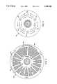
- FIG. 1An a.c. rotary electrical machine 10 according to this invention, which includes a plurality of rotor disks 12, 14, 16, mounted for rotation with main shaft 18. Interstitially disposed with rotor disks 12, 14 and 16 are a plurality of stator disks 20, 22, 24 and 26. While stator disks 20 and 26 at each end of machine 10 may be independently formed as are stator disks 22 and 24, this is not the case in FIG. 1. There the end stator disks 20 and 26 are integrally formed with end caps 28 and 30, which are made of magnetic material and form a part of the complete return element. Structure 32 is formed of cover 34 and end plate 36 bolted to cover 34 by means of bolts 38.
- Machine 10may be either an induction machine or a permanent magnet synchronous machine.
- the flux path 60has flux exiting 62 at end cap 30, axially transversing the machine through stator disks and rotor disks 26, 16, 24, 14, 22, 12 and 20, and entering the other end cap 28 so that a single serial flux path is being used for interaction with each of the rotor/stator air gap interfaces.
- the fluxreturns azimuthally through the end cap. The magnitude of the azimuthal flux density gradually diminishes, changes direction, and then gradually increases as explained subsequently with respect to FIG. 4.
- stator 22For an induction machine or permanent magnet synchronous machine, a stator typified by stator 22, FIG. 2, is made of non-conducting, non-magnetic material and contains thirty-six teeth 70 separated by thirty-six slots 72. Teeth 70 are embedded in stator disk 22 and are laminated. Disk 22 carries a poly-phase stator winding using embedded conductors. The stators may be made such that there need be no parent disc (i.e., disc 22). Instead the windings are potted into the slots between the wedge-shaped teeth. Then excess "iron” is machined away. In this embodiment the winding is shown as a three-phase winding 74 having phases A, B and C. Only a portion of phase A is shown.
- phase A windingthe pattern of windings 74 is extended around the full 360° of stator disk 22.
- Phases B and Care identical with phase A, but they are displaced by four and eight slots, respectively, relative to A. In this manner each slot contains a side of two adjacent coils.
- This windingis denominated a six pole, three phase, two coils per pole per phase, 5/6 fractional pitch winding, but any suitable winding may be used.
- the end stator disks 20 and 26are identical with the other stators having the same construction, number of teeth, and spacing. In this design there are twice as many windings in the intermediate stator disc as on the end stators. This need not be true, however.
- a rotor disc 12atypifying a rotor used for an induction machine, is made of a conducting material such as copper or aluminum. It also includes a number of magnetic teeth 80 which may be laminated and are separated by slots 82. The number of teeth on rotor disc 12a differ from the number of teeth on its adjacent stators. In this case the rotors have nineteen teeth and slots, while the stator has thirty-six teeth and slots.
- the current flow occurring in rotor disc 12ais similar to that in the stator.
- the currentsflow in loops 84, 86, through the conductor present around rotor teeth 80.
- the discrete arrows appearing around the surface of rotor disk 12aindicate the current direction where the current is largest. In some slots and return path locations, there is little current at a particular instant pictured, so no arrow is present.
- the return element portion element of end caps 28 and 30(FIG. 1) support a flux path, as shown in FIG. 4 with respect to end cap 28. There it can be seen that the flux flows azimuthally through the magnetic material. It enters in areas 90 and exits in areas 92. This depiction represents the flux at a particular instant of time. The pattern itself moves azimuthally with time.
- FIG. 1If machine 10, FIG. 1, were implemented as a permanent magnet synchronous machine, the stator disks would be constructed in the same way, but the rotor disks would be constructed differently as shown with respect to rotor disk 12b, FIG. 5.
- This rotor diskis constructed of permanent magnet material.
- the six poles 100, 102, 104, 106, 108 and 110can be constructed by magnetizing the disk appropriately or using six discrete permanent magnets installed or potted into the host disk. With rotor disks 12b, the flux flows into the paper at the south poles and out of the paper at the north poles. The axial polarization of poles 100-110 can be seen more clearly in the side view, FIG. 6, where the arrows graphically depict the flux directions.
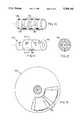
- Linear electrical machine 120FIG. 7 includes an armature or stator assembly 122 connected to a mechanical ground by shaft 123, and a plunger or shuttle assembly 124 akin to the rotor assembly of a rotary machine, which provides the power output on shaft 126.
- shuttle assembly 124includes two shuttles 128 and 130, while stator assembly 122 includes three stators 132, 134 and 136.
- stators 132, 134 and 136each includes a plurality of teeth 138 separated by slots 140, in which are located the windings 142.
- Shuttles 128 and 130when implementing an induction machine, as exemplified by shuttle 128, include a plurality of teeth 144 separated by conductive slots 146.
- Bearing 150establishes relative radial position between shuttle shaft 126 and stator assembly 122.
- the inner 152 and outer 154 back iron portionscomplete the return path for the magnetic flux. These back irons are shown disproportionately thin. More accurately, they are four times thicker than shown in FIG. 7.
- the linear machineoperates in the same way as the rotary machine according to this invention, except that the flux and current flows that occur axially in a rotary machine occur radially in the linear machine, and those that occur azimuthally in the rotor machine occur axially in the linear machine.
- the enlarged detail view in FIG. 7 of the diagram of FIG. 8shows with greater particularity the orientation of the three phases of current flow indicated as A, --A, B, --B, C and --C, located in the same slots 140 and the typical flux path is indicated at 160 with portions of the inner back iron broken away for clarity.
- linear machine 120aappears as shown in FIG. 9, where stators 132a, 134a and 136a are formed as cylinders, and specifically in this instance they are right circular cylinders, as are shuttles 128a and 130a.
- stators 132a, 134a and 136aare formed as cylinders, and specifically in this instance they are right circular cylinders, as are shuttles 128a and 130a.
- other cylindrical shapescould be used.
- shuttle 124bWhen linear machine 120 is constructed as an induction machine, shuttle 124b, FIG. 10, can be formed of alternate rings of magnetic material 180, such as iron, with the intermediate rings 182 being formed of some suitable conductor such as copper, where the current flow is depicted by arrows 184.
- magnetic material 180such as iron
- intermediate rings 182being formed of some suitable conductor such as copper
- shuttle 124cin the permanent magnet synchronous machine, shuttle 124c, FIG. 11, is formed of alternating magnetic rings 186 in which alternate ones 188 are polarized with their north poles on the circumference and the intermediate ones 190 have their south poles on the circumference.
- the polarizationcan be better seen in FIG. 12, which is a sectional view taken along line 12--12 of FIG. 11 through ring or annular portion 190, where the plurality at the circumference 192 is south polarized and the interior surface 194 of the annular ring is north polarized.
Landscapes
- Engineering & Computer Science (AREA)
- Power Engineering (AREA)
- Physics & Mathematics (AREA)
- Chemical & Material Sciences (AREA)
- Combustion & Propulsion (AREA)
- Electromagnetism (AREA)
- Permanent Magnet Type Synchronous Machine (AREA)
Abstract
Description
σ.sub.z =K.sub.x B.sub.y (1)
<σ>≦K.sub.x.sup.1 B.sub.y.sup.1 (2)
Claims (14)
Priority Applications (2)
| Application Number | Priority Date | Filing Date | Title |
|---|---|---|---|
| US08/069,080US5396140A (en) | 1993-05-28 | 1993-05-28 | Parallel air gap serial flux A.C. electrical machine |
| US08/290,511US5495131A (en) | 1993-05-28 | 1994-08-16 | Parallel air gap serial flux A.C. electrical machine |
Applications Claiming Priority (1)
| Application Number | Priority Date | Filing Date | Title |
|---|---|---|---|
| US08/069,080US5396140A (en) | 1993-05-28 | 1993-05-28 | Parallel air gap serial flux A.C. electrical machine |
Related Child Applications (1)
| Application Number | Title | Priority Date | Filing Date |
|---|---|---|---|
| US08/290,511DivisionUS5495131A (en) | 1993-05-28 | 1994-08-16 | Parallel air gap serial flux A.C. electrical machine |
Publications (1)
| Publication Number | Publication Date |
|---|---|
| US5396140Atrue US5396140A (en) | 1995-03-07 |
Family
ID=22086612
Family Applications (2)
| Application Number | Title | Priority Date | Filing Date |
|---|---|---|---|
| US08/069,080Expired - LifetimeUS5396140A (en) | 1993-05-28 | 1993-05-28 | Parallel air gap serial flux A.C. electrical machine |
| US08/290,511Expired - Fee RelatedUS5495131A (en) | 1993-05-28 | 1994-08-16 | Parallel air gap serial flux A.C. electrical machine |
Family Applications After (1)
| Application Number | Title | Priority Date | Filing Date |
|---|---|---|---|
| US08/290,511Expired - Fee RelatedUS5495131A (en) | 1993-05-28 | 1994-08-16 | Parallel air gap serial flux A.C. electrical machine |
Country Status (1)
| Country | Link |
|---|---|
| US (2) | US5396140A (en) |
Cited By (103)
| Publication number | Priority date | Publication date | Assignee | Title |
|---|---|---|---|---|
| WO1996037036A1 (en)* | 1995-05-18 | 1996-11-21 | Aura Systems, Inc. | Polyphase induction motor having a ferromagnetic rotor plate |
| US5619087A (en)* | 1992-03-18 | 1997-04-08 | Kabushiki Kaisha Toshiba | Axial-gap rotary-electric machine |
| US5633551A (en)* | 1994-04-15 | 1997-05-27 | Weh; Herbert | Machine with transverse flux |
| US5637939A (en)* | 1996-05-02 | 1997-06-10 | Chrysler Corporation | Pocket attachment to rim |
| US5656880A (en)* | 1993-02-17 | 1997-08-12 | Cadac Limited | Discoidal dynamo-electric machine |
| US5672920A (en)* | 1996-05-02 | 1997-09-30 | Chrysler Corporation | Current sharing AC Bus Bar |
| US5694301A (en)* | 1996-05-02 | 1997-12-02 | Chrysler Corporation | Power structure construction (DC bus cross straps) |
| US5694017A (en)* | 1996-05-02 | 1997-12-02 | Chrysler Corporation | Time delay compressed synchronous frame controller |
| US5696414A (en)* | 1996-05-02 | 1997-12-09 | Chrysler Corporation | Sliding spoke rotor to hub attachment |
| US5708579A (en)* | 1996-05-02 | 1998-01-13 | Chrysler Corporation | Gate driver supply |
| US5712519A (en)* | 1993-05-21 | 1998-01-27 | Magna Force, Inc. | Magnetic power transfer system |
| US5719459A (en)* | 1995-10-13 | 1998-02-17 | Toyota Jidosha Kabushiki Kaisha | Electric motor for a steering mechanism |
| US5721459A (en)* | 1996-05-02 | 1998-02-24 | Chrysler Corporation | Output voltage regulation using rotor growth |
| US5721461A (en)* | 1997-01-31 | 1998-02-24 | Lockheed Martin Vought Systems | Combined energy storage alternator and pulsed power alternator |
| WO1998009365A1 (en)* | 1996-08-29 | 1998-03-05 | Aura Systems, Inc. | Induction machine using ferromagnetic conducting rotor |
| US5731643A (en)* | 1996-05-02 | 1998-03-24 | Chrysler Coporation | Stator cooling assembly |
| US5740015A (en)* | 1996-05-02 | 1998-04-14 | Chrysler Corporation | Heat exchanger |
| US5744896A (en)* | 1996-05-21 | 1998-04-28 | Visual Computing Systems Corp. | Interlocking segmented coil array |
| US5757151A (en)* | 1996-05-02 | 1998-05-26 | Chrysler Corporation | DC pump drive module |
| US5761028A (en)* | 1996-05-02 | 1998-06-02 | Chrysler Corporation | Transistor connection assembly having IGBT (X) cross ties |
| US5767637A (en)* | 1996-05-02 | 1998-06-16 | Chrysler Corporation | Controller for turboal ternator |
| US5783893A (en)* | 1995-10-20 | 1998-07-21 | Newport News Shipbuilding And Dry Dock Company | Multiple stator, single shaft electric machine |
| US5783883A (en)* | 1996-05-02 | 1998-07-21 | Chrysler Corporation | Subcritical spoke for hub to rotor attachment |
| US5784927A (en)* | 1996-05-02 | 1998-07-28 | Rao; Gita P. | Laminated balance bars for an energy storage apparatus |
| US5789824A (en)* | 1996-05-02 | 1998-08-04 | Chrysler Corporation | Cooling of turboalternator for hybrid motor vehicle |
| US5789825A (en)* | 1996-05-02 | 1998-08-04 | Chrysler Corporation | Compressor of turboalternator for hybrid motor vehicle |
| US5793145A (en)* | 1996-05-02 | 1998-08-11 | Chrysler Corporation | End cap to rotor attachment |
| US5793142A (en)* | 1996-05-02 | 1998-08-11 | Chrysler Corporation | Solid rotor assembly |
| US5796173A (en)* | 1996-05-02 | 1998-08-18 | Chrysler Corporation | Hydraulic fit of turboalternator for hybrid motor vehicle |
| US5804724A (en)* | 1996-05-02 | 1998-09-08 | Chrysler Corporation | Rotor speed estimator |
| US5804761A (en)* | 1996-05-02 | 1998-09-08 | Chrysler Corporation | Water cooled DC bus structure |
| US5804898A (en)* | 1995-09-12 | 1998-09-08 | Nihon Riken Co., Ltd. | Electric motor utilizing magnetic energy of permanent magnet |
| US5808391A (en)* | 1996-05-02 | 1998-09-15 | Chrysler Corporation | Rotor squirrel cage construction |
| US5811900A (en)* | 1996-05-02 | 1998-09-22 | Chrysler Corporation | Segmented rim construction for a rotor |
| US5815907A (en)* | 1996-05-02 | 1998-10-06 | Chrysler Corporation | Method of forming a rim construction for a rotor |
| US5821650A (en)* | 1996-05-02 | 1998-10-13 | Chrysler Corporation | Soft magnet for a rotor |
| US5821651A (en)* | 1996-05-02 | 1998-10-13 | Chrysler Corporation | Flywheel controller |
| US5828554A (en)* | 1996-05-02 | 1998-10-27 | Chrysler Corporation | Integrated chassis, enclosure and cage |
| US5828137A (en)* | 1996-05-02 | 1998-10-27 | Chrysler Corporation | Turboalternator for hybrid motor vehicle |
| US5845731A (en)* | 1996-07-02 | 1998-12-08 | Chrysler Corporation | Hybrid motor vehicle |
| FR2764691A1 (en)* | 1997-06-12 | 1998-12-18 | Ensmse | Differential torque measuring device |
| US5852865A (en)* | 1996-05-02 | 1998-12-29 | Chrysler Corporation | Stator fabrication process |
| US5855055A (en)* | 1996-05-02 | 1999-01-05 | Chrysler Corporation | Method for assembling a stator |
| US5873560A (en)* | 1996-05-02 | 1999-02-23 | Chrysler Corporation | Gimbal support system with uni-directional roll stiffness |
| US5879128A (en)* | 1996-07-24 | 1999-03-09 | Applied Materials, Inc. | Lift pin and support pin apparatus for a processing chamber |
| US5884390A (en)* | 1996-05-02 | 1999-03-23 | Daimlerchrysler Corporation | Assembly process of magnet onto a rotor |
| US5892307A (en)* | 1995-03-07 | 1999-04-06 | Pavlovich; Lisseikine Viatcheslav | Brushless DC motor |
| US5923085A (en)* | 1996-05-02 | 1999-07-13 | Chrysler Corporation | IGBT module construction |
| US5925993A (en)* | 1996-05-02 | 1999-07-20 | Chrysler Corporation | Power control architecture for a hybrid power source |
| US5936422A (en)* | 1996-05-02 | 1999-08-10 | Chrysler Corporation | Method for testing and matching electrical components |
| US5952758A (en)* | 1997-03-20 | 1999-09-14 | Centre National De La Recherche Scientifique (C.N.R.S.) | Rotating electrical machine with excitation coils, by magnets or with double excitation |
| US5959382A (en)* | 1995-10-13 | 1999-09-28 | Milli Sensor Systems And Actuators, Inc. | Magnetic actuator and position control system |
| US5962943A (en)* | 1998-02-27 | 1999-10-05 | Sunstrand Corporation | Axial gap dynamoelectric machine |
| US5962941A (en)* | 1996-05-02 | 1999-10-05 | Chrysler Corporation | Spoke shape for hub to rotor attachment |
| US5982074A (en) | 1996-12-11 | 1999-11-09 | Advanced Technologies Int., Ltd. | Axial field motor/generator |
| US5999864A (en)* | 1997-04-23 | 1999-12-07 | Chrysler Corporation | Method of power management for a hybrid powertrain system |
| US6011337A (en)* | 1998-09-15 | 2000-01-04 | Lin; Shou-Mei | Double-sided, non-iron core, brushless, axial magnetic field permanent-magnet type DC motor |
| US6069424A (en)* | 1996-05-02 | 2000-05-30 | Chrysler Corporation | Stator cooling |
| US6073712A (en)* | 1997-01-23 | 2000-06-13 | Chrysler Corporation | Method of power output level control for a hybrid power train system |
| US6087750A (en)* | 1999-05-18 | 2000-07-11 | Pacific Scientific Electro Kinetics Division | Permanent magnet generator |
| US6097118A (en)* | 1998-10-30 | 2000-08-01 | University Of Chicago | Reluctance apparatus for flywheel energy storage |
| US6211589B1 (en) | 1995-06-07 | 2001-04-03 | The Boeing Company | Magnetic systems for energy storage flywheels |
| US20010008356A1 (en)* | 2000-01-19 | 2001-07-19 | Wilkin Geoffrey A | Rotor disc |
| US20010040414A1 (en)* | 2000-01-25 | 2001-11-15 | Wittig Michael B. | Electric motor |
| US6348751B1 (en) | 1997-12-12 | 2002-02-19 | New Generation Motors Corporation | Electric motor with active hysteresis-based control of winding currents and/or having an efficient stator winding arrangement and/or adjustable air gap |
| EP1301980A2 (en)* | 2001-02-20 | 2003-04-16 | E.I. Dupont de Nemours and Company | Segmented induction electric machine with interdigitated disk-type rotor and stator construction |
| US6717312B1 (en)* | 2001-01-03 | 2004-04-06 | Dana Corporation | Defense vehicle aiming ordinance platform having variable reluctance motor |
| US20040135452A1 (en)* | 2003-01-10 | 2004-07-15 | Sunyen Co., Ltd. | Flat rotary electric generator |
| WO2004064223A3 (en)* | 2003-01-13 | 2004-10-28 | Sunyen Co Ltd | Flat rotary electric generator |
| US20050206261A1 (en)* | 2003-04-15 | 2005-09-22 | Gts Research, Inc., A Nevada Corporation | Electromagnetic motor employing multiple rotors |
| US20060038516A1 (en)* | 2001-02-20 | 2006-02-23 | Burse Ronald O | Segmented switched reluctance electric machine with interdigitated disk-type rotor and stator construction |
| US20060138890A1 (en)* | 2004-12-14 | 2006-06-29 | Nissan Motor Co., Ltd. | Rotor structure of an axial gap rotating electrical device |
| US20060145562A1 (en)* | 2004-12-10 | 2006-07-06 | Nissan Motor Co., Ltd. | A stator structure of an axial gap rotating electrical device |
| US20070085435A1 (en)* | 2003-04-15 | 2007-04-19 | Godfrey Carl L | Electromagnetic motor employing multiple rotors |
| US20070210675A1 (en)* | 2006-03-13 | 2007-09-13 | Isca Innovations, Llc | Brushless electric motor |
| US20080024035A1 (en)* | 2006-07-31 | 2008-01-31 | Caterpillar Inc. | Power system |
| US20080024027A1 (en)* | 2006-07-31 | 2008-01-31 | Caterpillar Inc. | Axial-flux electric machine |
| EP1901418A1 (en)* | 2006-09-13 | 2008-03-19 | Whitehead Alenia Sistemi Subacquei S.p.A. | An axial-flux electric motor provided with a high-efficiency cooling system |
| US20090072639A1 (en)* | 2007-09-19 | 2009-03-19 | Richard Lex Seneff | Segmented composite rotor |
| CN101969261A (en)* | 2010-10-22 | 2011-02-09 | 哈尔滨工业大学 | High-power density permanent magnet motor |
| US20110109190A1 (en)* | 2009-11-09 | 2011-05-12 | Yasuaki Aoyama | Rotary electrical machine |
| US20110132530A1 (en)* | 2004-08-31 | 2011-06-09 | Avery Dennison Corporation | Adhesive Articles with Improved Air Egress and Methods of Making the Same |
| US20120175994A1 (en)* | 2011-01-11 | 2012-07-12 | Qm Power, Inc. | Magnetically Isolated Phase Interior Permanent Magnet Electrical Rotating Machine |
| US20120319518A1 (en)* | 2011-06-16 | 2012-12-20 | Uri Rapoport | High efficiency high output density electric motor |
| US20130062889A1 (en)* | 2010-03-23 | 2013-03-14 | Adaptive Generators As | Variable electrical generator |
| WO2014074008A1 (en)* | 2012-11-06 | 2014-05-15 | Esakov Sergej Mikhailovich | Electromagnetic motor |
| WO2014074009A1 (en)* | 2012-11-06 | 2014-05-15 | Esakov Sergej Mikhailovich | Electromagnetic generator |
| US8947185B2 (en) | 2010-07-12 | 2015-02-03 | Correlated Magnetics Research, Llc | Magnetic system |
| US9105384B2 (en) | 2008-04-04 | 2015-08-11 | Correlated Megnetics Research, Llc. | Apparatus and method for printing maxels |
| US9257219B2 (en) | 2012-08-06 | 2016-02-09 | Correlated Magnetics Research, Llc. | System and method for magnetization |
| US9275783B2 (en) | 2012-10-15 | 2016-03-01 | Correlated Magnetics Research, Llc. | System and method for demagnetization of a magnetic structure region |
| US9298281B2 (en) | 2012-12-27 | 2016-03-29 | Correlated Magnetics Research, Llc. | Magnetic vector sensor positioning and communications system |
| US9367783B2 (en) | 2009-06-02 | 2016-06-14 | Correlated Magnetics Research, Llc | Magnetizing printer and method for re-magnetizing at least a portion of a previously magnetized magnet |
| US20160254737A1 (en)* | 2015-02-26 | 2016-09-01 | James W. Purvis | Electromagnetic Angular Acceleration Propulsion System |
| US20170163114A1 (en)* | 2015-12-07 | 2017-06-08 | Hamilton Sundstrand Corporation | Motor-generator with multiple stator windings |
| US10075030B2 (en) | 2015-08-11 | 2018-09-11 | Genesis Robotics & Motion Technologies Canada, Ulc | Electric machine |
| US10164510B1 (en)* | 2017-09-27 | 2018-12-25 | Daniel Farley | Low resistance generator |
| US10270323B2 (en)* | 2017-09-27 | 2019-04-23 | Daniel Farley | Low resistance generator |
| US10381886B2 (en) | 2016-08-01 | 2019-08-13 | Hamilton Sundstrand Corporation | Motor-generator with radial-flux double-sided stator |
| US11043885B2 (en) | 2016-07-15 | 2021-06-22 | Genesis Robotics And Motion Technologies Canada, Ulc | Rotary actuator |
| US11139707B2 (en) | 2015-08-11 | 2021-10-05 | Genesis Robotics And Motion Technologies Canada, Ulc | Axial gap electric machine with permanent magnets arranged between posts |
| US20230163669A1 (en)* | 2020-05-29 | 2023-05-25 | Mitsubishi Electric Corporation | Rotary electric machine and aircraft using rotary electric machine |
| DE102021132895A1 (en) | 2021-12-14 | 2023-06-15 | Schaeffler Technologies AG & Co. KG | Electrical axial flux machine and method for manufacturing an axial flux machine |
Families Citing this family (48)
| Publication number | Priority date | Publication date | Assignee | Title |
|---|---|---|---|---|
| FI93340C (en)* | 1993-06-28 | 1995-03-27 | Kone Oy | The elevator machine |
| AU7075094A (en)* | 1993-06-28 | 1995-01-17 | Kone Oy | Elevator machinery |
| US5783895A (en)* | 1994-04-07 | 1998-07-21 | Kone Oy | Elevator motor with flat construction |
| FI114419B (en)* | 1994-04-07 | 2004-10-15 | Kone Corp | The elevator machinery |
| DE4408719C1 (en)* | 1994-03-15 | 1995-07-06 | Volkswagen Ag | Generator-motor combination |
| US5783894A (en)* | 1995-10-31 | 1998-07-21 | Wither; Thomas A. | Method and apparatus for generating electrical energy |
| KR100206762B1 (en)* | 1995-11-14 | 1999-07-01 | 구자홍 | Magnet assembly of linear motor |
| US6268667B1 (en)* | 1998-02-20 | 2001-07-31 | Advanced Motion Technologies, Llc | Apparatus for producing linear motion |
| EP0945963B1 (en)* | 1998-03-25 | 2003-11-05 | Nissan Motor Co., Ltd. | Motor/generator |
| DE69912666T2 (en)* | 1998-03-25 | 2004-05-13 | Nissan Motor Co., Ltd., Yokohama | Motor / generator |
| JP3196738B2 (en)* | 1998-09-11 | 2001-08-06 | 株式会社デンソー | Stator manufacturing apparatus and stator manufacturing method |
| US6066906A (en)* | 1999-02-17 | 2000-05-23 | American Superconductor Corporation | Rotating machine having superconducting windings |
| JP3589134B2 (en) | 2000-01-12 | 2004-11-17 | 株式会社デンソー | Stator manufacturing method and apparatus |
| US6670730B2 (en)* | 2001-04-12 | 2003-12-30 | Ballado Investments Inc. | Multi-phase linear motor with induction coils arranged on an axis perpendicular to the direction of motion |
| SE0104378D0 (en)* | 2001-12-21 | 2001-12-21 | Volvo Teknisk Utveckling Ab | Electrical device |
| US7218019B2 (en)* | 2002-12-06 | 2007-05-15 | Foster-Miller, Inc | Linear reluctance motor |
| US8004127B2 (en)* | 2002-12-06 | 2011-08-23 | Foster-Miller, Inc. | Rotary reluctance motor |
| MY136646A (en)* | 2004-05-11 | 2008-11-28 | Toshiba Elevator Kk | Magnet unit, elevator guiding apparatus and weighing apparatus |
| EP1839385B1 (en)* | 2005-01-22 | 2013-05-22 | Stefan Soter | Linear actuator |
| US9112395B2 (en)* | 2006-08-28 | 2015-08-18 | Youngtack Shim | Electromagnetically-countered actuator systems and methods |
| AU2012201158B2 (en)* | 2006-11-17 | 2012-11-08 | Wedge Global, S.L. | Switched reluctance linear motor/generator |
| ES2269012B1 (en)* | 2006-11-17 | 2007-10-16 | Julio LUCAS TORRALBA | GENERATOR / LINEAR MOTOR OF SWITCHED RELUCTANCE. |
| WO2008084964A2 (en)* | 2007-01-08 | 2008-07-17 | Lg Electronics, Inc. | Linear motor for linear compresser |
| US7941910B2 (en)* | 2007-03-22 | 2011-05-17 | Tecnomatic S.P.A. | Method for removing winding conductors from a twisting machine and placing them in a rotor stator stack |
| US8215000B2 (en) | 2007-07-20 | 2012-07-10 | Tecnomatic, S.P.A. | Methods for twisting rotor and stator ends |
| GB0801256D0 (en)* | 2008-01-24 | 2008-02-27 | Denne Phillip R M | Improvements in electrical machines |
| KR20100080957A (en)* | 2008-08-05 | 2010-07-14 | 엘지전자 주식회사 | Linear compressor |
| KR20100018416A (en)* | 2008-08-06 | 2010-02-17 | 엘지전자 주식회사 | Linear compressor |
| WO2010016723A1 (en)* | 2008-08-07 | 2010-02-11 | 엘지전자 주식회사 | Linear compressor |
| US8188633B2 (en)* | 2009-01-05 | 2012-05-29 | Eric Stephane Quere | Integrated composite electromechanical machines |
| JP5484861B2 (en)* | 2009-01-07 | 2014-05-07 | 山洋電気株式会社 | Linear motor |
| GB2479926B (en)* | 2010-04-30 | 2016-05-11 | Atherton Nigel | Electricity generator |
| JP5530319B2 (en)* | 2010-09-16 | 2014-06-25 | カヤバ工業株式会社 | Linear actuator |
| AR083135A1 (en)* | 2011-10-05 | 2013-02-06 | Ind Metalurgicas Pescarmona S A I C Y F | SYNCHRONIC WIND GENERATOR |
| RU2521048C1 (en)* | 2013-05-06 | 2014-06-27 | Сергей Михайлович Есаков | Magnetoelectric generator |
| NZ619034A (en)* | 2013-12-16 | 2015-03-27 | Eddy Current Ltd Partnership | An assembly to control relative speed of movement between parts |
| AU2015304095B2 (en) | 2014-08-18 | 2020-05-07 | Eddy Current Limited Partnership | Tuning of a kinematic relationship between members |
| BR112017003080B1 (en) | 2014-08-18 | 2022-10-25 | Eddy Current Limited Partnership | LOCKING DEVICES |
| CN110932523B (en) | 2014-08-18 | 2022-09-06 | 涡流有限合伙公司 | Adjustment of kinematic relationships between components |
| AU2015355674A1 (en) | 2014-12-04 | 2017-06-08 | Eddy Current Limited Partnership | Eddy current brake configurations |
| BR112017010692B1 (en) | 2014-12-04 | 2022-03-03 | Eddy Current Limited Partnership | Activation coupling between elements |
| EP3912685A1 (en) | 2014-12-04 | 2021-11-24 | Eddy Current Limited Partnership | Methods of altering eddy current interactions |
| CA2969423C (en) | 2014-12-04 | 2024-01-02 | Eddy Current Limited Partnership | Energy absorbing apparatus |
| BR112017010687A2 (en) | 2014-12-04 | 2017-12-26 | Eddy Current Lp | transmissions incorporating eddy current braking |
| MX384701B (en) | 2015-12-18 | 2025-03-14 | Eddy Current Lp | A VARIABLE BEHAVIOR CONTROL MECHANISM FOR A MOTOR SYSTEM. |
| US10710443B2 (en)* | 2016-10-18 | 2020-07-14 | Richard Chi-Hsueh | Multi-ring disc motor |
| KR102692165B1 (en)* | 2017-02-07 | 2024-08-06 | 엘지전자 주식회사 | transvers flux type recyprocating motor and recyprocating compressor having the same |
| US20240120818A1 (en)* | 2022-09-28 | 2024-04-11 | Rainer B. Meinke | Systems and methods combining discrete flux-directed magnet assemblies that integrate magnetic gear boxes with single or dual rotor machines |
Citations (6)
| Publication number | Priority date | Publication date | Assignee | Title |
|---|---|---|---|---|
| US3700944A (en)* | 1971-11-08 | 1972-10-24 | Ford Motor Co | Disc-type variable reluctance rotating machine |
| US4187441A (en)* | 1977-03-23 | 1980-02-05 | General Electric Company | High power density brushless dc motor |
| US4371801A (en)* | 1978-10-11 | 1983-02-01 | General Electric Company | Method and apparatus for output regulation of multiple disk permanent magnet machines |
| US4658166A (en)* | 1985-05-10 | 1987-04-14 | Portescap | Synchronous electric motor with disc-shaped permanent magnet rotor |
| US5021698A (en)* | 1988-07-26 | 1991-06-04 | Rolls Royce Plc | Axial field electrical generator |
| US5177392A (en)* | 1991-01-14 | 1993-01-05 | Westinghouse Electric Corp. | High efficiency, low reactance disk-type machine including an improved rotor and stator |
Family Cites Families (4)
| Publication number | Priority date | Publication date | Assignee | Title |
|---|---|---|---|---|
| US3881139A (en)* | 1973-11-16 | 1975-04-29 | Fujitsu Ltd | 3-Axis pulse operated linear motor |
| US4501980A (en)* | 1982-06-04 | 1985-02-26 | Motornetics Corporation | High torque robot motor |
| US4500827A (en)* | 1984-06-11 | 1985-02-19 | Merritt Thomas D | Linear reciprocating electrical generator |
| US4937481A (en)* | 1989-01-13 | 1990-06-26 | Mechanical Technology Incorporated | Permanent magnet linear electromagnetic machine |
- 1993
- 1993-05-28USUS08/069,080patent/US5396140A/ennot_activeExpired - Lifetime
- 1994
- 1994-08-16USUS08/290,511patent/US5495131A/ennot_activeExpired - Fee Related
Patent Citations (6)
| Publication number | Priority date | Publication date | Assignee | Title |
|---|---|---|---|---|
| US3700944A (en)* | 1971-11-08 | 1972-10-24 | Ford Motor Co | Disc-type variable reluctance rotating machine |
| US4187441A (en)* | 1977-03-23 | 1980-02-05 | General Electric Company | High power density brushless dc motor |
| US4371801A (en)* | 1978-10-11 | 1983-02-01 | General Electric Company | Method and apparatus for output regulation of multiple disk permanent magnet machines |
| US4658166A (en)* | 1985-05-10 | 1987-04-14 | Portescap | Synchronous electric motor with disc-shaped permanent magnet rotor |
| US5021698A (en)* | 1988-07-26 | 1991-06-04 | Rolls Royce Plc | Axial field electrical generator |
| US5177392A (en)* | 1991-01-14 | 1993-01-05 | Westinghouse Electric Corp. | High efficiency, low reactance disk-type machine including an improved rotor and stator |
Cited By (136)
| Publication number | Priority date | Publication date | Assignee | Title |
|---|---|---|---|---|
| US5619087A (en)* | 1992-03-18 | 1997-04-08 | Kabushiki Kaisha Toshiba | Axial-gap rotary-electric machine |
| US5656880A (en)* | 1993-02-17 | 1997-08-12 | Cadac Limited | Discoidal dynamo-electric machine |
| US5712519A (en)* | 1993-05-21 | 1998-01-27 | Magna Force, Inc. | Magnetic power transfer system |
| US5633551A (en)* | 1994-04-15 | 1997-05-27 | Weh; Herbert | Machine with transverse flux |
| US5892307A (en)* | 1995-03-07 | 1999-04-06 | Pavlovich; Lisseikine Viatcheslav | Brushless DC motor |
| US5734217A (en)* | 1995-05-18 | 1998-03-31 | Aura Systems, Inc. | Induction machine using ferromagnetic conducting material in rotor |
| WO1996037036A1 (en)* | 1995-05-18 | 1996-11-21 | Aura Systems, Inc. | Polyphase induction motor having a ferromagnetic rotor plate |
| US6211589B1 (en) | 1995-06-07 | 2001-04-03 | The Boeing Company | Magnetic systems for energy storage flywheels |
| US5804898A (en)* | 1995-09-12 | 1998-09-08 | Nihon Riken Co., Ltd. | Electric motor utilizing magnetic energy of permanent magnet |
| US5959382A (en)* | 1995-10-13 | 1999-09-28 | Milli Sensor Systems And Actuators, Inc. | Magnetic actuator and position control system |
| US5719459A (en)* | 1995-10-13 | 1998-02-17 | Toyota Jidosha Kabushiki Kaisha | Electric motor for a steering mechanism |
| US5783893A (en)* | 1995-10-20 | 1998-07-21 | Newport News Shipbuilding And Dry Dock Company | Multiple stator, single shaft electric machine |
| US5811900A (en)* | 1996-05-02 | 1998-09-22 | Chrysler Corporation | Segmented rim construction for a rotor |
| US5804761A (en)* | 1996-05-02 | 1998-09-08 | Chrysler Corporation | Water cooled DC bus structure |
| US5637939A (en)* | 1996-05-02 | 1997-06-10 | Chrysler Corporation | Pocket attachment to rim |
| US5731643A (en)* | 1996-05-02 | 1998-03-24 | Chrysler Coporation | Stator cooling assembly |
| US5721459A (en)* | 1996-05-02 | 1998-02-24 | Chrysler Corporation | Output voltage regulation using rotor growth |
| US5740015A (en)* | 1996-05-02 | 1998-04-14 | Chrysler Corporation | Heat exchanger |
| US5936422A (en)* | 1996-05-02 | 1999-08-10 | Chrysler Corporation | Method for testing and matching electrical components |
| US5757151A (en)* | 1996-05-02 | 1998-05-26 | Chrysler Corporation | DC pump drive module |
| US5761028A (en)* | 1996-05-02 | 1998-06-02 | Chrysler Corporation | Transistor connection assembly having IGBT (X) cross ties |
| US5767637A (en)* | 1996-05-02 | 1998-06-16 | Chrysler Corporation | Controller for turboal ternator |
| US5708579A (en)* | 1996-05-02 | 1998-01-13 | Chrysler Corporation | Gate driver supply |
| US5783883A (en)* | 1996-05-02 | 1998-07-21 | Chrysler Corporation | Subcritical spoke for hub to rotor attachment |
| US5784927A (en)* | 1996-05-02 | 1998-07-28 | Rao; Gita P. | Laminated balance bars for an energy storage apparatus |
| US5789824A (en)* | 1996-05-02 | 1998-08-04 | Chrysler Corporation | Cooling of turboalternator for hybrid motor vehicle |
| US5789825A (en)* | 1996-05-02 | 1998-08-04 | Chrysler Corporation | Compressor of turboalternator for hybrid motor vehicle |
| US5793145A (en)* | 1996-05-02 | 1998-08-11 | Chrysler Corporation | End cap to rotor attachment |
| US5793142A (en)* | 1996-05-02 | 1998-08-11 | Chrysler Corporation | Solid rotor assembly |
| US5796173A (en)* | 1996-05-02 | 1998-08-18 | Chrysler Corporation | Hydraulic fit of turboalternator for hybrid motor vehicle |
| US5804724A (en)* | 1996-05-02 | 1998-09-08 | Chrysler Corporation | Rotor speed estimator |
| US5694301A (en)* | 1996-05-02 | 1997-12-02 | Chrysler Corporation | Power structure construction (DC bus cross straps) |
| US5696414A (en)* | 1996-05-02 | 1997-12-09 | Chrysler Corporation | Sliding spoke rotor to hub attachment |
| US5808391A (en)* | 1996-05-02 | 1998-09-15 | Chrysler Corporation | Rotor squirrel cage construction |
| US5925993A (en)* | 1996-05-02 | 1999-07-20 | Chrysler Corporation | Power control architecture for a hybrid power source |
| US5815907A (en)* | 1996-05-02 | 1998-10-06 | Chrysler Corporation | Method of forming a rim construction for a rotor |
| US5821650A (en)* | 1996-05-02 | 1998-10-13 | Chrysler Corporation | Soft magnet for a rotor |
| US5821651A (en)* | 1996-05-02 | 1998-10-13 | Chrysler Corporation | Flywheel controller |
| US5828554A (en)* | 1996-05-02 | 1998-10-27 | Chrysler Corporation | Integrated chassis, enclosure and cage |
| US5828137A (en)* | 1996-05-02 | 1998-10-27 | Chrysler Corporation | Turboalternator for hybrid motor vehicle |
| US5672920A (en)* | 1996-05-02 | 1997-09-30 | Chrysler Corporation | Current sharing AC Bus Bar |
| US6069424A (en)* | 1996-05-02 | 2000-05-30 | Chrysler Corporation | Stator cooling |
| US5852865A (en)* | 1996-05-02 | 1998-12-29 | Chrysler Corporation | Stator fabrication process |
| US5855055A (en)* | 1996-05-02 | 1999-01-05 | Chrysler Corporation | Method for assembling a stator |
| US5873560A (en)* | 1996-05-02 | 1999-02-23 | Chrysler Corporation | Gimbal support system with uni-directional roll stiffness |
| US5962941A (en)* | 1996-05-02 | 1999-10-05 | Chrysler Corporation | Spoke shape for hub to rotor attachment |
| US5884390A (en)* | 1996-05-02 | 1999-03-23 | Daimlerchrysler Corporation | Assembly process of magnet onto a rotor |
| US5694017A (en)* | 1996-05-02 | 1997-12-02 | Chrysler Corporation | Time delay compressed synchronous frame controller |
| US5923085A (en)* | 1996-05-02 | 1999-07-13 | Chrysler Corporation | IGBT module construction |
| USRE38939E1 (en)* | 1996-05-21 | 2006-01-24 | Kinetic Art & Technology Corporation | Interlocking segmented coil array |
| US5744896A (en)* | 1996-05-21 | 1998-04-28 | Visual Computing Systems Corp. | Interlocking segmented coil array |
| US5845731A (en)* | 1996-07-02 | 1998-12-08 | Chrysler Corporation | Hybrid motor vehicle |
| US5879128A (en)* | 1996-07-24 | 1999-03-09 | Applied Materials, Inc. | Lift pin and support pin apparatus for a processing chamber |
| WO1998009365A1 (en)* | 1996-08-29 | 1998-03-05 | Aura Systems, Inc. | Induction machine using ferromagnetic conducting rotor |
| US5982074A (en) | 1996-12-11 | 1999-11-09 | Advanced Technologies Int., Ltd. | Axial field motor/generator |
| US6073712A (en)* | 1997-01-23 | 2000-06-13 | Chrysler Corporation | Method of power output level control for a hybrid power train system |
| US5721461A (en)* | 1997-01-31 | 1998-02-24 | Lockheed Martin Vought Systems | Combined energy storage alternator and pulsed power alternator |
| US5952758A (en)* | 1997-03-20 | 1999-09-14 | Centre National De La Recherche Scientifique (C.N.R.S.) | Rotating electrical machine with excitation coils, by magnets or with double excitation |
| US5999864A (en)* | 1997-04-23 | 1999-12-07 | Chrysler Corporation | Method of power management for a hybrid powertrain system |
| FR2764691A1 (en)* | 1997-06-12 | 1998-12-18 | Ensmse | Differential torque measuring device |
| US6348751B1 (en) | 1997-12-12 | 2002-02-19 | New Generation Motors Corporation | Electric motor with active hysteresis-based control of winding currents and/or having an efficient stator winding arrangement and/or adjustable air gap |
| US5962943A (en)* | 1998-02-27 | 1999-10-05 | Sunstrand Corporation | Axial gap dynamoelectric machine |
| US6011337A (en)* | 1998-09-15 | 2000-01-04 | Lin; Shou-Mei | Double-sided, non-iron core, brushless, axial magnetic field permanent-magnet type DC motor |
| US6097118A (en)* | 1998-10-30 | 2000-08-01 | University Of Chicago | Reluctance apparatus for flywheel energy storage |
| US6087750A (en)* | 1999-05-18 | 2000-07-11 | Pacific Scientific Electro Kinetics Division | Permanent magnet generator |
| US20010008356A1 (en)* | 2000-01-19 | 2001-07-19 | Wilkin Geoffrey A | Rotor disc |
| US6741010B2 (en)* | 2000-01-19 | 2004-05-25 | Rolls Royce Plc | Rotor disc assembly having rotor rim with alternate magnets and laminated pole pieces |
| US20010040414A1 (en)* | 2000-01-25 | 2001-11-15 | Wittig Michael B. | Electric motor |
| US6717312B1 (en)* | 2001-01-03 | 2004-04-06 | Dana Corporation | Defense vehicle aiming ordinance platform having variable reluctance motor |
| US20030210012A1 (en)* | 2001-02-20 | 2003-11-13 | Burse Ronald Odell | Segmented induction electric machine with interdigitated disk-type rotor and stator construction |
| US6803847B2 (en) | 2001-02-20 | 2004-10-12 | E. I. Du Pont De Nemours And Company | Segmented induction electric machine with interdigitated disk-type rotor and stator construction |
| US6713982B2 (en) | 2001-02-20 | 2004-03-30 | E. I. Du Pont De Nemours And Company | Segmented induction electric machine with interdigiated disk-type rotor and stator construction |
| EP1301980A2 (en)* | 2001-02-20 | 2003-04-16 | E.I. Dupont de Nemours and Company | Segmented induction electric machine with interdigitated disk-type rotor and stator construction |
| US20060038516A1 (en)* | 2001-02-20 | 2006-02-23 | Burse Ronald O | Segmented switched reluctance electric machine with interdigitated disk-type rotor and stator construction |
| US7427845B2 (en) | 2001-02-20 | 2008-09-23 | E. I. Du Pont De Nemours And Company | Segmented switched reluctance electric machine with interdigitated disk-type rotor and stator construction |
| US20040135452A1 (en)* | 2003-01-10 | 2004-07-15 | Sunyen Co., Ltd. | Flat rotary electric generator |
| US6794783B2 (en) | 2003-01-10 | 2004-09-21 | Sunyen Co., Ltd. | Flat rotary electric generator |
| GB2411775B (en)* | 2003-01-13 | 2006-11-15 | Sunyen Co Ltd | Flat rotary electric generator |
| WO2004064223A3 (en)* | 2003-01-13 | 2004-10-28 | Sunyen Co Ltd | Flat rotary electric generator |
| GB2411775A (en)* | 2003-01-13 | 2005-09-07 | Sunyen Co Ltd | Flat rotary electric generator |
| US20060138889A1 (en)* | 2003-04-15 | 2006-06-29 | Godfrey Carl L | Electromagnetic motor employing multiple rotors |
| US20050206261A1 (en)* | 2003-04-15 | 2005-09-22 | Gts Research, Inc., A Nevada Corporation | Electromagnetic motor employing multiple rotors |
| US20070085435A1 (en)* | 2003-04-15 | 2007-04-19 | Godfrey Carl L | Electromagnetic motor employing multiple rotors |
| US20070222318A1 (en)* | 2003-04-15 | 2007-09-27 | Gts Research, Inc. | Electromagnetic motor employing multiple rotors |
| US20110132531A1 (en)* | 2004-08-31 | 2011-06-09 | Avery Dennison Corporation | Adhesive Articles with Improved Air Egress and Methods of Making the Same |
| US20110132530A1 (en)* | 2004-08-31 | 2011-06-09 | Avery Dennison Corporation | Adhesive Articles with Improved Air Egress and Methods of Making the Same |
| US20060145562A1 (en)* | 2004-12-10 | 2006-07-06 | Nissan Motor Co., Ltd. | A stator structure of an axial gap rotating electrical device |
| US7579744B2 (en) | 2004-12-14 | 2009-08-25 | Nissan Motor Co., Ltd. | Rotor structure of an axial gap rotating electrical device |
| US20060138890A1 (en)* | 2004-12-14 | 2006-06-29 | Nissan Motor Co., Ltd. | Rotor structure of an axial gap rotating electrical device |
| US20070210675A1 (en)* | 2006-03-13 | 2007-09-13 | Isca Innovations, Llc | Brushless electric motor |
| US7471026B2 (en) | 2006-03-13 | 2008-12-30 | Isca Innovatons, Llc | Brushless electric motor |
| US20080024027A1 (en)* | 2006-07-31 | 2008-01-31 | Caterpillar Inc. | Axial-flux electric machine |
| US20080024035A1 (en)* | 2006-07-31 | 2008-01-31 | Caterpillar Inc. | Power system |
| US7557482B2 (en) | 2006-07-31 | 2009-07-07 | Caterpillar Inc. | Axial-flux electric machine |
| EP1901418A1 (en)* | 2006-09-13 | 2008-03-19 | Whitehead Alenia Sistemi Subacquei S.p.A. | An axial-flux electric motor provided with a high-efficiency cooling system |
| WO2008031883A1 (en)* | 2006-09-13 | 2008-03-20 | Whitehead Alenia Sistemi Subacquei S.P.A. | An axial-flux electric motor provided with a high-efficiency cooling system |
| US20090072639A1 (en)* | 2007-09-19 | 2009-03-19 | Richard Lex Seneff | Segmented composite rotor |
| US7714479B2 (en)* | 2007-09-19 | 2010-05-11 | Light Engineering, Inc. | Segmented composite rotor |
| US9536650B2 (en) | 2008-04-04 | 2017-01-03 | Correlated Magnetics Research, Llc. | Magnetic structure |
| US9105384B2 (en) | 2008-04-04 | 2015-08-11 | Correlated Megnetics Research, Llc. | Apparatus and method for printing maxels |
| US9269482B2 (en) | 2008-04-04 | 2016-02-23 | Correlated Magnetics Research, Llc. | Magnetizing apparatus |
| US9367783B2 (en) | 2009-06-02 | 2016-06-14 | Correlated Magnetics Research, Llc | Magnetizing printer and method for re-magnetizing at least a portion of a previously magnetized magnet |
| US20110109190A1 (en)* | 2009-11-09 | 2011-05-12 | Yasuaki Aoyama | Rotary electrical machine |
| US8680739B2 (en)* | 2009-11-09 | 2014-03-25 | Hitachi, Ltd. | Rotary electrical machine |
| US20130062889A1 (en)* | 2010-03-23 | 2013-03-14 | Adaptive Generators As | Variable electrical generator |
| US8878373B2 (en)* | 2010-03-23 | 2014-11-04 | Adaptive Generators As | Variable electrical generator |
| US9111672B2 (en) | 2010-07-12 | 2015-08-18 | Correlated Magnetics Research LLC. | Multilevel correlated magnetic system |
| US8947185B2 (en) | 2010-07-12 | 2015-02-03 | Correlated Magnetics Research, Llc | Magnetic system |
| CN101969261B (en)* | 2010-10-22 | 2012-06-27 | 哈尔滨工业大学 | High-power density permanent magnet motor |
| CN101969261A (en)* | 2010-10-22 | 2011-02-09 | 哈尔滨工业大学 | High-power density permanent magnet motor |
| WO2012097107A1 (en)* | 2011-01-11 | 2012-07-19 | Qm Power, Inc. | Magnetically isolated phase interior permanent magnet electrical rotating machine |
| RU2604650C2 (en)* | 2011-01-11 | 2016-12-10 | КьюЭм ПАУЭР, ИНК. | Magnetically isolated phase interior permanent magnet electrical rotating machine |
| US9812908B2 (en)* | 2011-01-11 | 2017-11-07 | Qm Power, Inc. | Magnetically isolated phase interior permanent magnet electrical rotating machine |
| US20120175994A1 (en)* | 2011-01-11 | 2012-07-12 | Qm Power, Inc. | Magnetically Isolated Phase Interior Permanent Magnet Electrical Rotating Machine |
| US20120319518A1 (en)* | 2011-06-16 | 2012-12-20 | Uri Rapoport | High efficiency high output density electric motor |
| US9000647B2 (en)* | 2011-06-16 | 2015-04-07 | Uri Rapoport | High efficiency high output density electric motor |
| US9257219B2 (en) | 2012-08-06 | 2016-02-09 | Correlated Magnetics Research, Llc. | System and method for magnetization |
| US9275783B2 (en) | 2012-10-15 | 2016-03-01 | Correlated Magnetics Research, Llc. | System and method for demagnetization of a magnetic structure region |
| WO2014074009A1 (en)* | 2012-11-06 | 2014-05-15 | Esakov Sergej Mikhailovich | Electromagnetic generator |
| WO2014074008A1 (en)* | 2012-11-06 | 2014-05-15 | Esakov Sergej Mikhailovich | Electromagnetic motor |
| US9298281B2 (en) | 2012-12-27 | 2016-03-29 | Correlated Magnetics Research, Llc. | Magnetic vector sensor positioning and communications system |
| US9588599B2 (en) | 2012-12-27 | 2017-03-07 | Correlated Magnetics Research, Llc. | Magnetic vector sensor positioning and communication system |
| US20160254737A1 (en)* | 2015-02-26 | 2016-09-01 | James W. Purvis | Electromagnetic Angular Acceleration Propulsion System |
| US10075030B2 (en) | 2015-08-11 | 2018-09-11 | Genesis Robotics & Motion Technologies Canada, Ulc | Electric machine |
| US11139707B2 (en) | 2015-08-11 | 2021-10-05 | Genesis Robotics And Motion Technologies Canada, Ulc | Axial gap electric machine with permanent magnets arranged between posts |
| US11043862B2 (en) | 2015-08-11 | 2021-06-22 | Genesis Robotics And Motion Technologies Canada, Ulc | Electric machine |
| US10476323B2 (en) | 2015-08-11 | 2019-11-12 | Genesis Robotics & Motion Technologies Canada, Ulc | Electric machine |
| US20170163114A1 (en)* | 2015-12-07 | 2017-06-08 | Hamilton Sundstrand Corporation | Motor-generator with multiple stator windings |
| US10270305B2 (en)* | 2015-12-07 | 2019-04-23 | Hamilton Sundstrand Corporation | Motor-generator with multiple stator windings |
| US11043885B2 (en) | 2016-07-15 | 2021-06-22 | Genesis Robotics And Motion Technologies Canada, Ulc | Rotary actuator |
| US10381886B2 (en) | 2016-08-01 | 2019-08-13 | Hamilton Sundstrand Corporation | Motor-generator with radial-flux double-sided stator |
| US10270323B2 (en)* | 2017-09-27 | 2019-04-23 | Daniel Farley | Low resistance generator |
| US10164510B1 (en)* | 2017-09-27 | 2018-12-25 | Daniel Farley | Low resistance generator |
| US20230163669A1 (en)* | 2020-05-29 | 2023-05-25 | Mitsubishi Electric Corporation | Rotary electric machine and aircraft using rotary electric machine |
| US12191723B2 (en)* | 2020-05-29 | 2025-01-07 | Mitsubishi Electric Corporation | Rotary electric machine having a stator core formed with stacked thin sheets and aircraft using the rotary electric machine core |
| DE102021132895A1 (en) | 2021-12-14 | 2023-06-15 | Schaeffler Technologies AG & Co. KG | Electrical axial flux machine and method for manufacturing an axial flux machine |
Also Published As
| Publication number | Publication date |
|---|---|
| US5495131A (en) | 1996-02-27 |
Similar Documents
| Publication | Publication Date | Title |
|---|---|---|
| US5396140A (en) | Parallel air gap serial flux A.C. electrical machine | |
| EP0199496B1 (en) | Permanent magnet variable reluctance generator | |
| US4134054A (en) | Homopolar synchronous machine | |
| US6844656B1 (en) | Electric multipole motor/generator with axial magnetic flux | |
| US4758756A (en) | Vernier-type electrodynamic machine | |
| US6175178B1 (en) | Low inductance electrical machine for flywheel energy storage | |
| US4200831A (en) | Compensated pulsed alternator | |
| US3974406A (en) | Electrical machine | |
| US3237036A (en) | Commutating dynamo-electric machine | |
| US7982352B2 (en) | Electrical motor/generator having a number of stator pole cores being larger than a number of rotor pole shoes | |
| US7382072B2 (en) | Generator | |
| US5929541A (en) | Synchronous machine | |
| US6100620A (en) | High frequency synchronous rotary electrical machine | |
| US4745318A (en) | Induction motor with secondary rotor | |
| WO2001029956A1 (en) | Low inductance electrical machine for flywheel energy storage | |
| US5798594A (en) | Brushless synchronous rotary electrical machine | |
| US5864197A (en) | Synchronous machine | |
| US4634912A (en) | Electromechanical transducer having a self-inductance cancelling coil assembly | |
| US20240243631A1 (en) | Axial flux induction motor or generator | |
| US4835431A (en) | Transformer and synchronous machine with stationary field winding | |
| US6191517B1 (en) | Brushless synchronous rotary electrical machine | |
| US4595871A (en) | Stepping motor of hybrid multi-phase type and device for its control | |
| RU2079949C1 (en) | Electrical machine | |
| US5952759A (en) | Brushless synchronous rotary electrical machine | |
| EP0960465A1 (en) | An electric machine |
Legal Events
| Date | Code | Title | Description |
|---|---|---|---|
| AS | Assignment | Owner name:SATCON TECHNOLOGY CORPORATION, MASSACHUSETTS Free format text:ASSIGNMENT OF ASSIGNORS INTEREST;ASSIGNORS:GOLDIE, JAMES H.;KIRTLEY, JAMES;REEL/FRAME:006588/0963 Effective date:19930521 | |
| STPP | Information on status: patent application and granting procedure in general | Free format text:APPLICATION UNDERGOING PREEXAM PROCESSING | |
| FPAY | Fee payment | Year of fee payment:4 | |
| FPAY | Fee payment | Year of fee payment:8 | |
| FEPP | Fee payment procedure | Free format text:PAYOR NUMBER ASSIGNED (ORIGINAL EVENT CODE: ASPN); ENTITY STATUS OF PATENT OWNER: SMALL ENTITY | |
| FPAY | Fee payment | Year of fee payment:12 | |
| AS | Assignment | Owner name:COMPASS HORIZON FUNDING COMPANY LLC,CONNECTICUT Free format text:SECURITY AGREEMENT;ASSIGNOR:SATCON TECHNOLOGY CORPORATION;REEL/FRAME:024576/0776 Effective date:20100616 | |
| AS | Assignment | Owner name:VELOCITY VENTURE HOLDINGS, LLC, ITS SUCCESSORS AND Free format text:SECURITY AGREEMENT;ASSIGNOR:COMPASS HORIZON FUNDING COMPANY LLC;REEL/FRAME:024838/0935 Effective date:20100813 | |
| AS | Assignment | Owner name:SILICON VALLEY BANK, MASSACHUSETTS Free format text:AMENDED AND RESTATED INTELLECTUAL PROPERTY SECURITY AGREEMENT;ASSIGNORS:SATCON TECHNOLOGY CORPORATION;SATCON POWER SYSTEMS, INC.;SATCON ELECTRONICS, INC.;AND OTHERS;REEL/FRAME:026196/0547 Effective date:20110421 | |
| AS | Assignment | Owner name:SATCON POWER SYSTEMS, INC., MASSACHUSETTS Free format text:RELEASE BY SECURED PARTY;ASSIGNOR:SILICON VALLEY BANK;REEL/FRAME:031515/0595 Effective date:20130805 Owner name:SATCON TECHNOLOGY CORPORATION, MASSACHUSETTS Free format text:RELEASE BY SECURED PARTY;ASSIGNOR:SILICON VALLEY BANK;REEL/FRAME:031515/0595 Effective date:20130805 Owner name:SATCON POWER SYSTEMS CANADA LTD., MASSACHUSETTS Free format text:RELEASE BY SECURED PARTY;ASSIGNOR:SILICON VALLEY BANK;REEL/FRAME:031515/0595 Effective date:20130805 Owner name:SATCON ELECTRONICS, INC., MASSACHUSETTS Free format text:RELEASE BY SECURED PARTY;ASSIGNOR:SILICON VALLEY BANK;REEL/FRAME:031515/0595 Effective date:20130805 Owner name:PERFECT GALAXY INTERNATIONAL LIMITED, HONG KONG Free format text:RELEASE BY SECURED PARTY;ASSIGNOR:SILICON VALLEY BANK;REEL/FRAME:031515/0595 Effective date:20130805 | |
| AS | Assignment | Owner name:PERFECT GALAXY INTERNATIONAL LIMITED, HONG KONG Free format text:ASSIGNMENT OF ASSIGNORS INTEREST;ASSIGNOR:SATCON TECHNOLOGY CORPORATION;REEL/FRAME:031638/0454 Effective date:20130805 |