US5395452A - Apparatus made of silica for semiconductor device fabrication - Google Patents
Apparatus made of silica for semiconductor device fabricationDownload PDFInfo
- Publication number
- US5395452A US5395452AUS08/077,645US7764593AUS5395452AUS 5395452 AUS5395452 AUS 5395452AUS 7764593 AUS7764593 AUS 7764593AUS 5395452 AUS5395452 AUS 5395452A
- Authority
- US
- United States
- Prior art keywords
- silica
- silica layer
- amount
- semiconductor device
- device fabrication
- Prior art date
- Legal status (The legal status is an assumption and is not a legal conclusion. Google has not performed a legal analysis and makes no representation as to the accuracy of the status listed.)
- Expired - Lifetime
Links
Images


Classifications
- H—ELECTRICITY
- H01—ELECTRIC ELEMENTS
- H01L—SEMICONDUCTOR DEVICES NOT COVERED BY CLASS H10
- H01L21/00—Processes or apparatus adapted for the manufacture or treatment of semiconductor or solid state devices or of parts thereof
- H01L21/02—Manufacture or treatment of semiconductor devices or of parts thereof
- H—ELECTRICITY
- H01—ELECTRIC ELEMENTS
- H01L—SEMICONDUCTOR DEVICES NOT COVERED BY CLASS H10
- H01L21/00—Processes or apparatus adapted for the manufacture or treatment of semiconductor or solid state devices or of parts thereof
- H01L21/67—Apparatus specially adapted for handling semiconductor or electric solid state devices during manufacture or treatment thereof; Apparatus specially adapted for handling wafers during manufacture or treatment of semiconductor or electric solid state devices or components ; Apparatus not specifically provided for elsewhere
- H01L21/67005—Apparatus not specifically provided for elsewhere
- H01L21/67011—Apparatus for manufacture or treatment
- H01L21/67098—Apparatus for thermal treatment
- H01L21/67115—Apparatus for thermal treatment mainly by radiation
- C—CHEMISTRY; METALLURGY
- C23—COATING METALLIC MATERIAL; COATING MATERIAL WITH METALLIC MATERIAL; CHEMICAL SURFACE TREATMENT; DIFFUSION TREATMENT OF METALLIC MATERIAL; COATING BY VACUUM EVAPORATION, BY SPUTTERING, BY ION IMPLANTATION OR BY CHEMICAL VAPOUR DEPOSITION, IN GENERAL; INHIBITING CORROSION OF METALLIC MATERIAL OR INCRUSTATION IN GENERAL
- C23C—COATING METALLIC MATERIAL; COATING MATERIAL WITH METALLIC MATERIAL; SURFACE TREATMENT OF METALLIC MATERIAL BY DIFFUSION INTO THE SURFACE, BY CHEMICAL CONVERSION OR SUBSTITUTION; COATING BY VACUUM EVAPORATION, BY SPUTTERING, BY ION IMPLANTATION OR BY CHEMICAL VAPOUR DEPOSITION, IN GENERAL
- C23C16/00—Chemical coating by decomposition of gaseous compounds, without leaving reaction products of surface material in the coating, i.e. chemical vapour deposition [CVD] processes
- C23C16/44—Chemical coating by decomposition of gaseous compounds, without leaving reaction products of surface material in the coating, i.e. chemical vapour deposition [CVD] processes characterised by the method of coating
- C23C16/4401—Means for minimising impurities, e.g. dust, moisture or residual gas, in the reaction chamber
- C23C16/4404—Coatings or surface treatment on the inside of the reaction chamber or on parts thereof
- C—CHEMISTRY; METALLURGY
- C30—CRYSTAL GROWTH
- C30B—SINGLE-CRYSTAL GROWTH; UNIDIRECTIONAL SOLIDIFICATION OF EUTECTIC MATERIAL OR UNIDIRECTIONAL DEMIXING OF EUTECTOID MATERIAL; REFINING BY ZONE-MELTING OF MATERIAL; PRODUCTION OF A HOMOGENEOUS POLYCRYSTALLINE MATERIAL WITH DEFINED STRUCTURE; SINGLE CRYSTALS OR HOMOGENEOUS POLYCRYSTALLINE MATERIAL WITH DEFINED STRUCTURE; AFTER-TREATMENT OF SINGLE CRYSTALS OR A HOMOGENEOUS POLYCRYSTALLINE MATERIAL WITH DEFINED STRUCTURE; APPARATUS THEREFOR
- C30B25/00—Single-crystal growth by chemical reaction of reactive gases, e.g. chemical vapour-deposition growth
- C30B25/02—Epitaxial-layer growth
- C30B25/08—Reaction chambers; Selection of materials therefor
- C—CHEMISTRY; METALLURGY
- C30—CRYSTAL GROWTH
- C30B—SINGLE-CRYSTAL GROWTH; UNIDIRECTIONAL SOLIDIFICATION OF EUTECTIC MATERIAL OR UNIDIRECTIONAL DEMIXING OF EUTECTOID MATERIAL; REFINING BY ZONE-MELTING OF MATERIAL; PRODUCTION OF A HOMOGENEOUS POLYCRYSTALLINE MATERIAL WITH DEFINED STRUCTURE; SINGLE CRYSTALS OR HOMOGENEOUS POLYCRYSTALLINE MATERIAL WITH DEFINED STRUCTURE; AFTER-TREATMENT OF SINGLE CRYSTALS OR A HOMOGENEOUS POLYCRYSTALLINE MATERIAL WITH DEFINED STRUCTURE; APPARATUS THEREFOR
- C30B31/00—Diffusion or doping processes for single crystals or homogeneous polycrystalline material with defined structure; Apparatus therefor
- C30B31/06—Diffusion or doping processes for single crystals or homogeneous polycrystalline material with defined structure; Apparatus therefor by contacting with diffusion material in the gaseous state
- C30B31/10—Reaction chambers; Selection of materials therefor
- H—ELECTRICITY
- H01—ELECTRIC ELEMENTS
- H01L—SEMICONDUCTOR DEVICES NOT COVERED BY CLASS H10
- H01L21/00—Processes or apparatus adapted for the manufacture or treatment of semiconductor or solid state devices or of parts thereof
- H01L21/67—Apparatus specially adapted for handling semiconductor or electric solid state devices during manufacture or treatment thereof; Apparatus specially adapted for handling wafers during manufacture or treatment of semiconductor or electric solid state devices or components ; Apparatus not specifically provided for elsewhere
- H01L21/673—Apparatus specially adapted for handling semiconductor or electric solid state devices during manufacture or treatment thereof; Apparatus specially adapted for handling wafers during manufacture or treatment of semiconductor or electric solid state devices or components ; Apparatus not specifically provided for elsewhere using specially adapted carriers or holders; Fixing the workpieces on such carriers or holders
- H01L21/67313—Horizontal boat type carrier whereby the substrates are vertically supported, e.g. comprising rod-shaped elements
Definitions
- the materials for jigs used in the heat treatment processparticularly require high purity, that is, the reduction in the amount of metal impurities contained therein.
- jigs made of silica, SiC and the likeare used. These materials are also required to be reduced in the contents of the impurities.
- the silica tube ccontains a wafer boat made of silica b mounting a semiconductor wafers w.
- the silica formed by the oxyhydrogen flame fusion methodis worse in the heat resistance and tends to be deformed by the applying of heat.
- the electrical fusion methodhas been developed for solving the disadvantage of the oxyhydrogen flame fusion method.
- the silica formed by the electrical fusion methodis,excellent in the heat resistance.
- the above two methodsproduce the silica using the natural silica rock or silica sand as the raw material.
- the silica thus obtainedcontains contaminated elements in a large amount. Accordingly, it is required to suppress the release of these contaminated elements to the outside of the silica.
- a silica tubeis so constructed that a high purity synthesis silica layer by vapor deposition is formed on the inner peripheral surface of a hard silica tube formed by the electrical fusion method. This is intended to prevent the internal diffusion of impurities by the synthesis silica layer.
- the synthesis silica layeris small in the content of impurities but is large in the content of the OH group. As a consequence, the synthesis silica layer is small in its viscosity and is worse in the heat resistance, thus causing such an inconvenience that it tends to be fused to the other members when exposed to high temperatures.
- the content of the OH group in a first silica layer on the side faced to a semiconductor waferis made larger, while the content of the OH group in a second silica layer on the opposed side is made smaller.
- this structureis possible to make difficult the deformation, and to significantly reduce the amount of the impurities released to the outside through the first silica layer. This is because the diffused amount of the contaminated metals is restricted by a large amount of the OH group.
- a third silica layeris interposed between the first and second silica layers, wherein the content of the OH group contained in the third silica layer is made larger than that of the first silica layer.
- the impurities permeating from the outside and reaching the first silica layerare entrapped by the third silica layer. This makes it possible to prevent the diffusion of the impurities into the first silica layer, and hence to further reduce the released amount of the impurities from the apparatus made of silica.
- the first silica layeris formed by the oxyhydrogen flame fusion method
- the second silica layeris formed by the electrical fusion method
- the third silica layeris formed by the vapor deposition method.
- FIGs. 1(A) and 1(B)are sectional views each showing one example of prior art apparatuses
- FIGS. 2(A) and 2(B)are sectional views each showing a method for examining the amount of impurities released from a silica layer
- FIGS. 3(A) and 3(B)are sectional views each showing a furnace tube made of silica according to a first embodiment of the present invention used for a fabrication process for semiconductor devices;
- FIGS. 4(A) and 4(B)are sectional views each showing a method for examining the amount of impurities released from the silica layer used in the first embodiment of the present invention
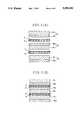
- FIGS. 5(A) and 5(B)are sectional views each showing a silica made furnace tube according to a second embodiment of the present invention used for a fabrication process for semiconductor devices;
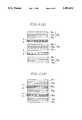
- FIGS. 6(A) and 6(B)are sectional views each showing a method for examining the amount of impurities released from the silica layer used in the second embodiment of the present invention
- FIG. 7(A)is a front view showing a wafer basket according to a third embodiment of the present invention used for a fabrication process
- FIG. 7(B)is a partial sectional view of the wafer basket as shown in FIG. 7(A);
- FIG. 7(C)is a sectional side view of the wafer basket as shown in 7(A);
- FIG. 7(D)is a partial sectional view of the wafer basket as shown in FIG. 7(A);
- FIG. 7(E)is a sectional side view of the wafer basket as shown in FIG. 7(A);
- FIGS. 8(A) and 8(B)are sectional views each showing a stick according to a fourth embodiment of the present invention used for a fabrication process for semiconductor devices.
- the silica formed by the oxyhydrogen flame fusion methodcontains the OH group in an amount of about 200 ppm or more.
- the silica formed by the electrical fusion methodcontains the OH group in a small amount of 30 ppm or less.
- the synthesis silica formed by the vapor deposition methodcontains the OH group in a large amount ranging from several hundreds to several thousands of ppm.
- each silica formed by the oxyhydrogen flame fusion method and the electrical fusion methodis examined for the metal impurities released therefrom in high temperatures.
- the examination for the amount of transition metals released from the silicais carried out by such a procedure as shown in FIG. 2(A) and FIG. 2(B).
- a silicon nitride film Yis formed on the surface of a silicon substrate X.
- a sample of a silica board Zis then contacted with the silicon nitride film Y.
- the silicon substrate X and the silica board Zare left, for example in a nitrogen atmosphere at 1100uiC for 6 hours.
- the impurities in the silica board Zis allowed to be released in the silicon nitride film Y.
- the above silicon nitride film Yis dissolved by a hydrofluoric acid solution, and the metal elements contained in the hydrofluoric acid solution are analyzed using an atomic absorption spectrometer.
- the silica containing a small amount of the OH grouphas a strong bonding between the Si and O and is thus excellent in the heat resistance; however, it becomes the source of the metal contamination to a semiconductor wafer in the actual heat treatment. Also, as is apparent from Tables 1 and 2, the heat resistance and the released amount of impurities cannot be determined depending on the content of the transition metals.
- the reason why the difference in the silica fabrication method exerts an influence on the released amount of contaminated metals under the high temperature heat treatmentis as follows: namely, metal impurities in the silica are entrapped by the OH group in some form, which retards the diffusion rate of the metal impurities in the silica.
- FIG. 3(A)is a sectional side view of an apparatus showing a first embodiment of the present invention
- FIG. 3(B)is a front view thereof.
- numeral 1indicates a horizontal type furnace tube used in a film deposition apparatus and an annealer and the like.
- the furnace tube 1has a two-layer structure with silica layers 2 and 3.
- the inner silica layer 2is formed by the oxyhydrogen flame fusion method and contains the OH group in an amount of 100 ppm or more.
- the outer silica layer 3is formed by, for example electrical fusion method and contains the OH group in an amount of 30 ppm or less.
- the oxyhydrogen flame fusion methodhas a process of fusing silica sand or silica rock by a flame of the supplied oxygen and hydrogen.
- the silica thus formedcontains a large amount of the OH group by the oxygen and hydrogen.
- the electrical fusion methodhas a process of fusing silica sand or silica rock in a vacuum atmosphere by a heater.
- the silica thus formedcontains a small amount of the Oh group under the principle of the electrical fusion method.
- the above furnace tube 1is used for the film deposition apparatus or the heater for semiconductor device fabrication, it is surround by a heater H and contains a wafer boat 4 mounting semiconductor wafers W.
- the outer silica layer 3contains a small amount of the OH group and metals such as Fe, Cu, Cr, Ni and the like in the respective amounts as shown in Table 1, and thereby the above metals tend to be diffused in the inner silica layer 2.
- the inner silica layer 2contains a large amount of the OH group, and thereby the metals are entrapped in some form by a large amount of the OH group. This makes it possible to retard the diffusion rate of the metals, and hence to reduce the amount of the metals released to the inner space of the furnace tube 1.
- the metal impuritieswhich are diffused through the wall of the furnace tube 1 from the heater wire constituting the heater H and permeated into the internal space of the furnace tube 1, are entrapped within the inner silica layer 2 having the small diffusion constant of the metals, thus substantially achieving the contamination blocking effect.
- the outer silica layer 3has a small amount of the OH group, and is not soften at, for example 1100C, so that the furnace tube 1 itself is not deformed in the processes for semiconductor device fabrication.
- a furnace tube having a two layer structurethere are considered the following methods: One involves preparing two silica tubes in which the outer diameter of the inner tube and the inside diameter of the outer tube are different by about 1 mm; inserting the inner tube in the outer tube; and melting them by the burner or the like for integrating them. The other involves applying a powder such as silica sand or silica rock on the inner surface of the outer silica tube containing the small amount of the OH group; inserting the inner tube in the outer tube; and fusing them in an atmosphere of oxygen and hydrogen.
- a powdersuch as silica sand or silica rock
- the analysiswas made using the contamination detecting wafer, that is, the silicon substrate X covered with the silicon nitride film Y used in obtaining the results shown in Table 2.
- FIGS. 4(A) and 4(B)there were prepared three samples Q each having a two-layer structure constituting an electrical fused silica layer q 1 having a thickness of 4 mm and a flame fused silica layer q 2 having a thickness of 1 mm.
- a first contamination detecting waferwas held between the flame fused silica layers q 2 of the first and second samples Q, and further, a second contamination detecting wafer was held between the electrical fused silica layers q 1 of the second and third samples Q. These were left in a nitrogen atmosphere at 1100° C. for 6 hours.
- the silicon nitride films Y of the two contamination detecting waferswere dissolved in the hydrofluoric acid solution, and were subjected to the atomic absorption spectrometry, which gave the results as shown in Table 3.
- the furnace tube having the outer layer constituted of the electric fused silica and the inner layer constituted of the flame fused silicais excellent in the heat resistance and is reduced in the amount of the metals released in the inside of the furnace tube. Further, the above furnace tube blocks metals released from the heater, and accordingly it is effectively applied to the process for semiconductor device fabrication.
- FIGS. 5(A) and 5(B)are a sectional side view and a sectional front view each showing a structure of a silica tube according to a second embodiment of the present invention.
- numeral 21indicates a horizontal type furnace tube used for the film deposition apparatus, annealer and the like.
- the furnace tube 21has a three-layer silica structure.
- a first and outermost silica layer 22is formed by the electric fusion method and contains the OH group in an amount of 30 ppm or less.
- a third and innermost silica layer 24is formed by the oxyhydrogen flame fusion method and contains the OH group in an amount of 100 ppm or more.
- a second silica layer 23 held between the silica layers 22 and 24is a synthesis silica layer formed by a vapor deposition method, and contains the OH group in an amount of 200 ppm or more, which is larger than that of the third silica layer 24.
- a reaction gascomposed of, for example SiCl 4 , H 2 and O 2 .
- the innermost silica layer 24contains a large amount of the OH group, the contaminated metals are entrapped therein in some form, which makes it possible to reduce the amount of the contaminated metals released to the inner space of the furnace tube 1.
- the metal impurities diffused from the electrical fused silica layer 22 or the metal impurities diffused to the furnace tube 1 from the outside such as the heater wire of the furnace and the likeare reduced in the diffusion rate in the second synthesis silica layer 23, thereby making it possible to reduce the amount of the contaminated elements released into the tube as compared with the first embodiment.
- the furnace tube constituted of the three-silica layer structureis excellent in the heat resistance and is substantially clean against the semiconductor wafers.
- FIG. 6(A)there were prepared three samples Q 3 each having a three-layer structure constituting an electrical fused silica layer q 11 having a thickness of 5 mm, a flame fused silica layer q 12 having a thickness of 1 mm and a synthesis silica layer q 13 having a thickness of 5 mm.
- a first contamination detecting waferwas held between the flame fused silica layers q 12 of the first and second samples Q 3
- a second contamination detecting waferwas held between the electrical fused silica layers q 11 of the second and third samples Q 3 .
- the silicon nitride films Y of the two contamination detecting waferswere dissolved in the different hydrofluoric acid solutions, and are subjected to the atomic absorption spectrometer, which gave the results as shown in Table 4.
- the silica board having the two-layer structure constituted of the electric fused silica layer and the flame fused silica layer used in the first embodimentAs is apparent from Table 4, as compared with the silica board having the two-layer structure constituted of the electric fused silica layer and the flame fused silica layer used in the first embodiment, the silica board having the three-layer structure in which the synthesis silica is held therebetween becomes smaller in the amount of the released metals, and accordingly it is more effectively applied to the process for semiconductor device fabrication.
- FIG. 7(A)is a front view of the wafer basket 4 as shown in FIGS. 2(B) and 3(B);
- FIG. 7(B)is a partial sectional view of the broken line seen from the front surface;
- FIG. 7(C)is a sectional side view thereof.
- a plurality of flame bodies 4aare disposed to be spacedly parallel to each other.
- the bottom portion and both sides of the frame body 4aare integrated with each other by bar-like bridging portions (not shown), respectively.
- Legs 4bare provided on the bottom portion, and projections 4c and grooves 4d for supporting a semiconductor wafer W are formed on the inner side (closest to the wafer W) of the frame body 4a.
- the wafer basket 4is constituted of a silica layer 5 as a base body and an outer silica layer 6 covering the silica layer 5.
- the silica layer 5 as a base bodyis constituted of a silica material formed by the electrical fusion method, and contains the OH group in a small amount of 30 ppm or less so as not to be soften at temperatures over several hundreds ° C.
- the silica layer 6 for coveringis constituted of a silica material formed by the oxyhydrogen flame fusion method, and contains the OH group in an amount of 100 ppm or more.
- the heavy metals such as Fe, Cu and the like contained in natural silicaare entrapped by a large amount of the OH group contained in the outer silica layer 6 and are thus difficult to be leaked.
- FIG. 8(A)is a sectional view of a fourth embodiment showing a stick made of silica used for semiconductor device fabrication.
- the stickis constituted of a silica layer 8 constituting a core portion, and a silica layer 9 covering the whole.
- the silica layer 8 constituting the core portioncontains the OH group in a small amount of, for example 30 ppm or less, and is formed by the electrical fusion method so as not to be soften in temperatures of several hundreds ° C.
- the silica layer 9 for coveringis formed by the oxyhydrogen flame fusion method and contains the OH group in a large amount of, for example 100 ppm or more.
- the above stickmakes it possible to suppress the leak of the metals such as Fe and Cu to the outside, and hence to extremely improve the amount of the contamination of the semiconductor wafer W.
- a synthesis silica layer 10between the silica layer 8 constituting the core portion and the silica layer 9 for covering.
- the synthesis silica layer 10contains the OH group in an amount larger than that of the silica layer 9 for covering.
- the silica layer as a base bodyis formed by the electrical fusion method to reduce the amount of the OH group, and the silica layer on the side (closest to the wafer side) faced to the semiconductor wafer is formed by the oxyhydrogen flame fusion method to increase the OH group, which covers the silica layer as a base body.
- a synthesis silicamay be interposed as an intermediate layer.
Landscapes
- Chemical & Material Sciences (AREA)
- Engineering & Computer Science (AREA)
- Materials Engineering (AREA)
- Organic Chemistry (AREA)
- Metallurgy (AREA)
- Condensed Matter Physics & Semiconductors (AREA)
- General Physics & Mathematics (AREA)
- Manufacturing & Machinery (AREA)
- Computer Hardware Design (AREA)
- Microelectronics & Electronic Packaging (AREA)
- Power Engineering (AREA)
- Physics & Mathematics (AREA)
- General Chemical & Material Sciences (AREA)
- Crystallography & Structural Chemistry (AREA)
- Chemical Kinetics & Catalysis (AREA)
- Health & Medical Sciences (AREA)
- Toxicology (AREA)
- Mechanical Engineering (AREA)
- Glass Compositions (AREA)
- Chemical Vapour Deposition (AREA)
Abstract
Description
TABLE 1 ______________________________________ METAL Fe Cu Cr Ni OH ELEMENT (ppb) (ppb) (ppb) (ppb) (ppm) ______________________________________ FLAME FUSED 74 <7 <10 <3 200 SILICA ELECTRICAL 57 <7 <10 <3 15.3 FUSED SILICA ______________________________________
TABLE 2 ______________________________________ METAL ELEMENT Fe Cr Ni Cu ______________________________________ FLAME FUSED SILICA 9.4 <0.52 <2.3 20 ELECTRICAL FUSED 1500 4.9 49 1200 SILICA (× 10.sup.10 atoms/cm.sup.2) ______________________________________
TABLE 3 ______________________________________ METAL ELEMENT Fe Cr Ni Cu ______________________________________ WAFER BETWEEN 3800 17 22 2700 ELECTRICAL FUSED SILICA LAYERS WAFER BETWEEN FLAME 130 0.55 <2.1 180 FUSED SILICA LAYERS (× 10.sup.10 atoms/cm.sup.2) ______________________________________
TABLE 4 ______________________________________ METAL ELEMENT Fe Cr Ni Cu ______________________________________ WAFER BETWEEN ELECTRICAL 3800 17 22 2700 FUSED SILICA LAYERS WAFER BETWEEN FLAME 11 3.4 3.1 36 FUSED SILICA LAYERS (× 10.sup.10 atoms/cm.sup.2) ______________________________________
Claims (36)
Applications Claiming Priority (4)
| Application Number | Priority Date | Filing Date | Title |
|---|---|---|---|
| JP16146292 | 1992-06-19 | ||
| JP4-161462 | 1992-06-19 | ||
| JP5-060342 | 1993-03-19 | ||
| JP06034293AJP3253734B2 (en) | 1992-06-19 | 1993-03-19 | Quartz equipment for semiconductor device manufacturing |
Publications (1)
| Publication Number | Publication Date |
|---|---|
| US5395452Atrue US5395452A (en) | 1995-03-07 |
Family
ID=26401411
Family Applications (1)
| Application Number | Title | Priority Date | Filing Date |
|---|---|---|---|
| US08/077,645Expired - LifetimeUS5395452A (en) | 1992-06-19 | 1993-06-17 | Apparatus made of silica for semiconductor device fabrication |
Country Status (5)
| Country | Link |
|---|---|
| US (1) | US5395452A (en) |
| EP (1) | EP0574935B1 (en) |
| JP (1) | JP3253734B2 (en) |
| KR (1) | KR970002425B1 (en) |
| DE (1) | DE69322546T2 (en) |
Cited By (24)
| Publication number | Priority date | Publication date | Assignee | Title |
|---|---|---|---|---|
| US5498292A (en)* | 1994-06-16 | 1996-03-12 | Kishimoto Sangyo Co., Ltd. | Heating device used for a gas phase growing mechanism or heat treatment mechanism |
| US5567242A (en)* | 1991-08-16 | 1996-10-22 | Sandvik Ab | Apparatus for depositing diamond coating in reactor equipped with a bowl-shaped substrate |
| US5882722A (en)* | 1995-07-12 | 1999-03-16 | Partnerships Limited, Inc. | Electrical conductors formed from mixtures of metal powders and metallo-organic decompositions compounds |
| US6245147B1 (en) | 1997-12-16 | 2001-06-12 | Fujitsu Limited | Thermal processing jig for use in manufacturing semiconductor devices and method of manufacturing the same |
| US20030148024A1 (en)* | 2001-10-05 | 2003-08-07 | Kodas Toivo T. | Low viscosity precursor compositons and methods for the depositon of conductive electronic features |
| US20030161959A1 (en)* | 2001-11-02 | 2003-08-28 | Kodas Toivo T. | Precursor compositions for the deposition of passive electronic features |
| US20030175411A1 (en)* | 2001-10-05 | 2003-09-18 | Kodas Toivo T. | Precursor compositions and methods for the deposition of passive electrical components on a substrate |
| US20030180451A1 (en)* | 2001-10-05 | 2003-09-25 | Kodas Toivo T. | Low viscosity copper precursor compositions and methods for the deposition of conductive electronic features |
| US20060159899A1 (en)* | 2005-01-14 | 2006-07-20 | Chuck Edwards | Optimized multi-layer printing of electronics and displays |
| US20060158497A1 (en)* | 2005-01-14 | 2006-07-20 | Karel Vanheusden | Ink-jet printing of compositionally non-uniform features |
| US20060159603A1 (en)* | 2005-01-14 | 2006-07-20 | Cabot Corporation | Separation of metal nanoparticles |
| US20060158470A1 (en)* | 2005-01-14 | 2006-07-20 | Cabot Corporation | Printable electronic features on non-uniform substrate and processes for making same |
| US20060159838A1 (en)* | 2005-01-14 | 2006-07-20 | Cabot Corporation | Controlling ink migration during the formation of printable electronic features |
| US20060163744A1 (en)* | 2005-01-14 | 2006-07-27 | Cabot Corporation | Printable electrical conductors |
| US20060190917A1 (en)* | 2005-01-14 | 2006-08-24 | Cabot Corporation | System and process for manufacturing application specific printable circuits (ASPC'S) and other custom electronic devices |
| US20060190918A1 (en)* | 2005-01-14 | 2006-08-24 | Cabot Corporation | System and process for manufacturing custom electronics by combining traditional electronics with printable electronics |
| US20070104605A1 (en)* | 1997-02-24 | 2007-05-10 | Cabot Corporation | Silver-containing particles, method and apparatus of manufacture, silver-containing devices made therefrom |
| US20070190298A1 (en)* | 2005-01-14 | 2007-08-16 | Cabot Corporation | Security features, their use and processes for making them |
| US20100112195A1 (en)* | 2001-10-19 | 2010-05-06 | Kodas Toivo T | Method for the fabrication of conductive electronic features |
| US8333820B2 (en) | 1997-02-24 | 2012-12-18 | Cabot Corporation | Forming conductive features of electronic devices |
| US8383014B2 (en) | 2010-06-15 | 2013-02-26 | Cabot Corporation | Metal nanoparticle compositions |
| US20130168377A1 (en)* | 2011-12-29 | 2013-07-04 | Stmicroelectronics Pte Ltd. | Adapter for coupling a diffusion furnace system |
| US8597397B2 (en) | 2005-01-14 | 2013-12-03 | Cabot Corporation | Production of metal nanoparticles |
| CN113889403A (en)* | 2021-12-08 | 2022-01-04 | 陕西亚成微电子股份有限公司 | Gate oxide layer growth method |
Families Citing this family (2)
| Publication number | Priority date | Publication date | Assignee | Title |
|---|---|---|---|---|
| TW460943B (en)* | 1997-06-11 | 2001-10-21 | Applied Materials Inc | Reduction of mobile ion and metal contamination in HDP-CVD chambers using chamber seasoning film depositions |
| KR100345304B1 (en)* | 2000-10-12 | 2002-07-25 | 한국전자통신연구원 | Apparatus for perpendicular-type ultra vacuum chemical vapor deposition |
Citations (10)
| Publication number | Priority date | Publication date | Assignee | Title |
|---|---|---|---|---|
| JPS55126542A (en)* | 1979-03-23 | 1980-09-30 | Fujitsu Ltd | Melting crucible for glass for optical transmission line |
| EP0046355A1 (en)* | 1980-08-18 | 1982-02-24 | Fujitsu Limited | Quartz tube for thermal processing of semiconductor substrates |
| US4317668A (en)* | 1980-01-21 | 1982-03-02 | Hitachi, Ltd. | Method for producing silica glass |
| US4664747A (en)* | 1985-03-28 | 1987-05-12 | Anelva Corporation | Surface processing apparatus utilizing local thermal equilibrium plasma and method of using same |
| WO1988005836A1 (en)* | 1987-02-09 | 1988-08-11 | Tsl Group Plc | Method of improving the sag resistance of a component constructed from fused quartz |
| JPS63236723A (en)* | 1987-03-26 | 1988-10-03 | Shinetsu Sekiei Kk | Quartz glass products for semiconductor industry |
| US4830982A (en)* | 1986-12-16 | 1989-05-16 | American Telephone And Telegraph Company | Method of forming III-V semi-insulating films using organo-metallic titanium dopant precursors |
| JPH0384922A (en)* | 1989-08-29 | 1991-04-10 | Shinetsu Sekiei Kk | Quartz glass tube for heat treatment of semiconductor |
| JPH03170340A (en)* | 1989-08-31 | 1991-07-23 | Shinetsu Sekiei Kk | Production of composite silica glass tube for heat treatment of semiconductor |
| US5119761A (en)* | 1990-01-19 | 1992-06-09 | Kabushiki Kaisha Toshiba | Substrate heating apparatus for forming thin films on substrate surface |
- 1993
- 1993-03-19JPJP06034293Apatent/JP3253734B2/ennot_activeExpired - Lifetime
- 1993-06-17KRKR93011122Apatent/KR970002425B1/ennot_activeExpired - Fee Related
- 1993-06-17USUS08/077,645patent/US5395452A/ennot_activeExpired - Lifetime
- 1993-06-18EPEP93109746Apatent/EP0574935B1/ennot_activeExpired - Lifetime
- 1993-06-18DEDE69322546Tpatent/DE69322546T2/ennot_activeExpired - Fee Related
Patent Citations (10)
| Publication number | Priority date | Publication date | Assignee | Title |
|---|---|---|---|---|
| JPS55126542A (en)* | 1979-03-23 | 1980-09-30 | Fujitsu Ltd | Melting crucible for glass for optical transmission line |
| US4317668A (en)* | 1980-01-21 | 1982-03-02 | Hitachi, Ltd. | Method for producing silica glass |
| EP0046355A1 (en)* | 1980-08-18 | 1982-02-24 | Fujitsu Limited | Quartz tube for thermal processing of semiconductor substrates |
| US4664747A (en)* | 1985-03-28 | 1987-05-12 | Anelva Corporation | Surface processing apparatus utilizing local thermal equilibrium plasma and method of using same |
| US4830982A (en)* | 1986-12-16 | 1989-05-16 | American Telephone And Telegraph Company | Method of forming III-V semi-insulating films using organo-metallic titanium dopant precursors |
| WO1988005836A1 (en)* | 1987-02-09 | 1988-08-11 | Tsl Group Plc | Method of improving the sag resistance of a component constructed from fused quartz |
| JPS63236723A (en)* | 1987-03-26 | 1988-10-03 | Shinetsu Sekiei Kk | Quartz glass products for semiconductor industry |
| JPH0384922A (en)* | 1989-08-29 | 1991-04-10 | Shinetsu Sekiei Kk | Quartz glass tube for heat treatment of semiconductor |
| JPH03170340A (en)* | 1989-08-31 | 1991-07-23 | Shinetsu Sekiei Kk | Production of composite silica glass tube for heat treatment of semiconductor |
| US5119761A (en)* | 1990-01-19 | 1992-06-09 | Kabushiki Kaisha Toshiba | Substrate heating apparatus for forming thin films on substrate surface |
Non-Patent Citations (2)
| Title |
|---|
| Database WPI Week 9135, Derwent Publications Ltd., London, GB; AN 91 258087 & JP A 03 170 340 (Shin Etsu) 23 Jul. 1991.* |
| Database WPI Week 9135, Derwent Publications Ltd., London, GB; AN 91-258087 & JP-A-3170 340 (Shin-Etsu) 23 Jul. 1991. |
Cited By (42)
| Publication number | Priority date | Publication date | Assignee | Title |
|---|---|---|---|---|
| US5567242A (en)* | 1991-08-16 | 1996-10-22 | Sandvik Ab | Apparatus for depositing diamond coating in reactor equipped with a bowl-shaped substrate |
| US5498292A (en)* | 1994-06-16 | 1996-03-12 | Kishimoto Sangyo Co., Ltd. | Heating device used for a gas phase growing mechanism or heat treatment mechanism |
| US5882722A (en)* | 1995-07-12 | 1999-03-16 | Partnerships Limited, Inc. | Electrical conductors formed from mixtures of metal powders and metallo-organic decompositions compounds |
| US6036889A (en)* | 1995-07-12 | 2000-03-14 | Parelec, Inc. | Electrical conductors formed from mixtures of metal powders and metallo-organic decomposition compounds |
| US20070104605A1 (en)* | 1997-02-24 | 2007-05-10 | Cabot Corporation | Silver-containing particles, method and apparatus of manufacture, silver-containing devices made therefrom |
| US8333820B2 (en) | 1997-02-24 | 2012-12-18 | Cabot Corporation | Forming conductive features of electronic devices |
| US7621976B2 (en) | 1997-02-24 | 2009-11-24 | Cabot Corporation | Coated silver-containing particles, method and apparatus of manufacture, and silver-containing devices made therefrom |
| US6245147B1 (en) | 1997-12-16 | 2001-06-12 | Fujitsu Limited | Thermal processing jig for use in manufacturing semiconductor devices and method of manufacturing the same |
| US7629017B2 (en) | 2001-10-05 | 2009-12-08 | Cabot Corporation | Methods for the deposition of conductive electronic features |
| US20070120098A1 (en)* | 2001-10-05 | 2007-05-31 | Cabot Corporation | Low viscosity precursor compositions and methods for the deposition of conductive electronic features |
| US20030148024A1 (en)* | 2001-10-05 | 2003-08-07 | Kodas Toivo T. | Low viscosity precursor compositons and methods for the depositon of conductive electronic features |
| US20030175411A1 (en)* | 2001-10-05 | 2003-09-18 | Kodas Toivo T. | Precursor compositions and methods for the deposition of passive electrical components on a substrate |
| US7524528B2 (en) | 2001-10-05 | 2009-04-28 | Cabot Corporation | Precursor compositions and methods for the deposition of passive electrical components on a substrate |
| US20080093422A1 (en)* | 2001-10-05 | 2008-04-24 | Cabot Corporation | Low viscosity precursor compositions and methods for the deposition of conductive electronic features |
| US20080008822A1 (en)* | 2001-10-05 | 2008-01-10 | Cabot Corporation | Controlling ink migration during the formation of printable electronic features |
| US20030180451A1 (en)* | 2001-10-05 | 2003-09-25 | Kodas Toivo T. | Low viscosity copper precursor compositions and methods for the deposition of conductive electronic features |
| US20070120099A1 (en)* | 2001-10-05 | 2007-05-31 | Cabot Corporation | Low viscosity precursor compositions and methods for the deposition of conductive electronic features |
| US7732002B2 (en) | 2001-10-19 | 2010-06-08 | Cabot Corporation | Method for the fabrication of conductive electronic features |
| US20100112195A1 (en)* | 2001-10-19 | 2010-05-06 | Kodas Toivo T | Method for the fabrication of conductive electronic features |
| US20030161959A1 (en)* | 2001-11-02 | 2003-08-28 | Kodas Toivo T. | Precursor compositions for the deposition of passive electronic features |
| US7553512B2 (en) | 2001-11-02 | 2009-06-30 | Cabot Corporation | Method for fabricating an inorganic resistor |
| US20060190918A1 (en)* | 2005-01-14 | 2006-08-24 | Cabot Corporation | System and process for manufacturing custom electronics by combining traditional electronics with printable electronics |
| US20060159603A1 (en)* | 2005-01-14 | 2006-07-20 | Cabot Corporation | Separation of metal nanoparticles |
| US20070034052A1 (en)* | 2005-01-14 | 2007-02-15 | Cabot Corporation | Production of metal nanoparticles |
| US20060159899A1 (en)* | 2005-01-14 | 2006-07-20 | Chuck Edwards | Optimized multi-layer printing of electronics and displays |
| US20060190917A1 (en)* | 2005-01-14 | 2006-08-24 | Cabot Corporation | System and process for manufacturing application specific printable circuits (ASPC'S) and other custom electronic devices |
| US7533361B2 (en) | 2005-01-14 | 2009-05-12 | Cabot Corporation | System and process for manufacturing custom electronics by combining traditional electronics with printable electronics |
| US20060189113A1 (en)* | 2005-01-14 | 2006-08-24 | Cabot Corporation | Metal nanoparticle compositions |
| US7575621B2 (en) | 2005-01-14 | 2009-08-18 | Cabot Corporation | Separation of metal nanoparticles |
| US20060163744A1 (en)* | 2005-01-14 | 2006-07-27 | Cabot Corporation | Printable electrical conductors |
| US20060159838A1 (en)* | 2005-01-14 | 2006-07-20 | Cabot Corporation | Controlling ink migration during the formation of printable electronic features |
| US20060158470A1 (en)* | 2005-01-14 | 2006-07-20 | Cabot Corporation | Printable electronic features on non-uniform substrate and processes for making same |
| US20070190298A1 (en)* | 2005-01-14 | 2007-08-16 | Cabot Corporation | Security features, their use and processes for making them |
| US7749299B2 (en) | 2005-01-14 | 2010-07-06 | Cabot Corporation | Production of metal nanoparticles |
| US8167393B2 (en) | 2005-01-14 | 2012-05-01 | Cabot Corporation | Printable electronic features on non-uniform substrate and processes for making same |
| US8334464B2 (en) | 2005-01-14 | 2012-12-18 | Cabot Corporation | Optimized multi-layer printing of electronics and displays |
| US20060158497A1 (en)* | 2005-01-14 | 2006-07-20 | Karel Vanheusden | Ink-jet printing of compositionally non-uniform features |
| US8668848B2 (en) | 2005-01-14 | 2014-03-11 | Cabot Corporation | Metal nanoparticle compositions for reflective features |
| US8597397B2 (en) | 2005-01-14 | 2013-12-03 | Cabot Corporation | Production of metal nanoparticles |
| US8383014B2 (en) | 2010-06-15 | 2013-02-26 | Cabot Corporation | Metal nanoparticle compositions |
| US20130168377A1 (en)* | 2011-12-29 | 2013-07-04 | Stmicroelectronics Pte Ltd. | Adapter for coupling a diffusion furnace system |
| CN113889403A (en)* | 2021-12-08 | 2022-01-04 | 陕西亚成微电子股份有限公司 | Gate oxide layer growth method |
Also Published As
| Publication number | Publication date |
|---|---|
| KR940006182A (en) | 1994-03-23 |
| DE69322546D1 (en) | 1999-01-28 |
| DE69322546T2 (en) | 1999-04-29 |
| EP0574935B1 (en) | 1998-12-16 |
| JPH0669145A (en) | 1994-03-11 |
| JP3253734B2 (en) | 2002-02-04 |
| EP0574935A1 (en) | 1993-12-22 |
| KR970002425B1 (en) | 1997-03-05 |
Similar Documents
| Publication | Publication Date | Title |
|---|---|---|
| US5395452A (en) | Apparatus made of silica for semiconductor device fabrication | |
| EP0529694B1 (en) | Process for thermal treatment of glass fiber preform | |
| DE69221152T2 (en) | VERTICAL HEAT TREATMENT DEVICE AND HEAT INSULATION MATERIAL | |
| US5916378A (en) | Method of reducing metal contamination during semiconductor processing in a reactor having metal components | |
| US4987016A (en) | Component for producing semiconductor devices and process of producing it | |
| US6245147B1 (en) | Thermal processing jig for use in manufacturing semiconductor devices and method of manufacturing the same | |
| US4587928A (en) | Apparatus for producing a semiconductor device | |
| US3446659A (en) | Apparatus and process for growing noncontaminated thermal oxide on silicon | |
| US4999228A (en) | Silicon carbide diffusion tube for semi-conductor | |
| KR100280693B1 (en) | Heat treatment equipment | |
| US4341818A (en) | Method for producing silicon dioxide/polycrystalline silicon interfaces | |
| JP2610050B2 (en) | Quartz glass tube for semiconductor heat treatment | |
| JP3426011B2 (en) | Semiconductor manufacturing apparatus and semiconductor device manufacturing method | |
| JP3066232B2 (en) | Semiconductor wafer heat treatment equipment | |
| CN1305540A (en) | Method and apparatus for producing silicon crystals with reduced metal content | |
| JPH0739227Y2 (en) | Multi-layered quartz glass furnace core tube | |
| JP7524826B2 (en) | Pretreatment method for heat treatment furnace, heat treatment furnace, and wafer manufacturing method | |
| JP3294356B2 (en) | Quartz glass furnace core tube for semiconductor wafer processing | |
| JP2606932Y2 (en) | Vertical wafer holding boat | |
| JPH031528A (en) | Composite silica, manufacture thereof and semiconductor manufacturing jig using same | |
| JPS6296349A (en) | Quartz glass reaction tube for heat-treatment of semiconductor | |
| JPH03246932A (en) | Manufacture equipment for semiconductor | |
| JPH027516A (en) | Method of diffusing impurity in semiconductor | |
| Groupe | Periodic precipitation in copper doped glasses. | |
| JPH08165134A (en) | Quartz glass for silicon semiconductor element heat treatment jig |
Legal Events
| Date | Code | Title | Description |
|---|---|---|---|
| AS | Assignment | Owner name:FUJITSU LIMITED, JAPAN Free format text:ASSIGNMENT OF ASSIGNORS INTEREST;ASSIGNORS:KOBAYASHI, MASANORI;YAMAZAKI, KEN;OGAWA, TSUTOMU;AND OTHERS;REEL/FRAME:006619/0071 Effective date:19930611 | |
| STPP | Information on status: patent application and granting procedure in general | Free format text:APPLICATION UNDERGOING PREEXAM PROCESSING | |
| FEPP | Fee payment procedure | Free format text:PAYOR NUMBER ASSIGNED (ORIGINAL EVENT CODE: ASPN); ENTITY STATUS OF PATENT OWNER: LARGE ENTITY | |
| CC | Certificate of correction | ||
| CC | Certificate of correction | ||
| FPAY | Fee payment | Year of fee payment:4 | |
| FPAY | Fee payment | Year of fee payment:8 | |
| FPAY | Fee payment | Year of fee payment:12 | |
| AS | Assignment | Owner name:FUJITSU MICROELECTRONICS LIMITED, JAPAN Free format text:ASSIGNMENT OF ASSIGNORS INTEREST;ASSIGNOR:FUJITSU LIMITED;REEL/FRAME:021985/0715 Effective date:20081104 Owner name:FUJITSU MICROELECTRONICS LIMITED,JAPAN Free format text:ASSIGNMENT OF ASSIGNORS INTEREST;ASSIGNOR:FUJITSU LIMITED;REEL/FRAME:021985/0715 Effective date:20081104 | |
| AS | Assignment | Owner name:FUJITSU SEMICONDUCTOR LIMITED, JAPAN Free format text:CHANGE OF NAME;ASSIGNOR:FUJITSU MICROELECTRONICS LIMITED;REEL/FRAME:024794/0500 Effective date:20100401 |