US5395385A - Apparatus for surgically re-profiling the cornea - Google Patents
Apparatus for surgically re-profiling the corneaDownload PDFInfo
- Publication number
- US5395385A US5395385AUS07/979,424US97942492AUS5395385AUS 5395385 AUS5395385 AUS 5395385AUS 97942492 AUS97942492 AUS 97942492AUS 5395385 AUS5395385 AUS 5395385A
- Authority
- US
- United States
- Prior art keywords
- cornea
- eye
- tool
- profiling tool
- knife edge
- Prior art date
- Legal status (The legal status is an assumption and is not a legal conclusion. Google has not performed a legal analysis and makes no representation as to the accuracy of the status listed.)
- Expired - Fee Related
Links
Images


Classifications
- A—HUMAN NECESSITIES
- A61—MEDICAL OR VETERINARY SCIENCE; HYGIENE
- A61B—DIAGNOSIS; SURGERY; IDENTIFICATION
- A61B17/00—Surgical instruments, devices or methods
- A61B17/32—Surgical cutting instruments
- A—HUMAN NECESSITIES
- A61—MEDICAL OR VETERINARY SCIENCE; HYGIENE
- A61F—FILTERS IMPLANTABLE INTO BLOOD VESSELS; PROSTHESES; DEVICES PROVIDING PATENCY TO, OR PREVENTING COLLAPSING OF, TUBULAR STRUCTURES OF THE BODY, e.g. STENTS; ORTHOPAEDIC, NURSING OR CONTRACEPTIVE DEVICES; FOMENTATION; TREATMENT OR PROTECTION OF EYES OR EARS; BANDAGES, DRESSINGS OR ABSORBENT PADS; FIRST-AID KITS
- A61F9/00—Methods or devices for treatment of the eyes; Devices for putting in contact-lenses; Devices to correct squinting; Apparatus to guide the blind; Protective devices for the eyes, carried on the body or in the hand
- A61F9/007—Methods or devices for eye surgery
- A61F9/013—Instruments for compensation of ocular refraction ; Instruments for use in cornea removal, for reshaping or performing incisions in the cornea
Definitions
- This inventionrelates to a method and apparatus for adjusting the shape of components of the eye and more particularly to making fixed changes in the corneal curvature.
- Deviations from the normal shape of the corneal surfaceproduce errors of refraction in the visual process.
- the eye in a state of rest, without accommodation,focuses the image of distant objects exactly on the retina.
- Such an eyeenjoys distinct vision for distant objects without effort.
- Any variation from this standardconstitutes ametropia, a condition in which the eye at rest is unable to focus the image of a distant object on the retina.
- Hyperopiais an error of refraction in which, with the eye at rest, parallel rays from distant objects are brought to focus behind the retina. Divergent rays from near objects are focused still further back.
- the corneal surfaceis flattened which decreases the angle of refraction of rays as they pass through the refractive surfaces of the cornea, causing a convergence or focus of the rays at a point behind the retina.
- the retinais comprised partially of nerve fibers which are an expansion of the optic nerve. Waves of light falling on the retina are converted into nerve impulses and carried by the optic nerve to the brain to produce the sensation of light.
- the hyperopic eyemust either accommodate, i.e., increase the convexity of its lens, or a convex lens of sufficient strength to focus rays on the retina must be placed before the eye.
- Myopiais that refractive condition in which, with accommodation completely relaxed, parallel rays are brought to focus in front of the retina.
- One condition which commonly causes myopiais when the corneal curvature is steepened, thus the refraction of rays is greater as they pass through the refractive surfaces of the cornea, and the over refracted rays converge or focus in front of the retina in the vitreous of the eye.
- the raysreach the retina they become divergent, forming a circle of diffusion and consequently a blurred image.
- a concave lensis used to correct the focus of the eye for myopia.
- Keratorefractive techniquesTwo such techniques are more particularly called keratophakia and keratomileusis. Keralomileusis involves the regrinding of a corneal lamella into a meniscus or hyperopic lens to correct myopia or hyperopia.
- a corneal optical lathehas been especially developed for this procedure and is also used in the keratophakia procedure, when a homograft ground into a convex lens is placed interlamellarly to correct aphakic hypermetropia.
- the homograft tissue(corneal lamella) is frozen with carbon dioxide.
- the homograftis cut as a contact lens would be, i.e., to the optical power required to effect the desired optical correction of the cornea.
- the anterior corneal lamellais shaped by the lathe and in keratophobia, it is the corneal stroma of a donor eye that is shaped by the lathe.
- the effect of a peripheral distorting forcemay be easily visualized by imagining an inflated balloon with a spherical surface being compressed between the palms of the hands. Because the volume of air in the balloon is constant, the surface area remains constant. The previously spherical anterior surface is distorted meridianally as a result of compressing the diameter between the hands so that the curvature changes without changing the circumference of the surface. The meridian passing over the balloon between the extended fingers steepens, while the uncompressed meridian at right angles thereto flattens as its diameter lengthens in proportion to the shortening of the compressed diameter.
- Exemer lasersrequire delivery of the beam to the eye in a controlled manner requiring that the homogenous beam be appropriately managed and focused because the optical elements must withstand the high energy photons, and because the beam must be shaped to a non-uniform configuration to create the new non-uniform optical surface of the cornea.
- Such delivery systemcontains multiple components including lenses to expand or focus the beam, mirrors to direct the beam, modulators to homogenize the beam, masks to shape the beam, and detectors to measure the intensity and configuration of the beam.
- Current modelsrange from a simple collection of lenses and masks to complex robots with components that control not only the laser parameters but also the optical and mechanical components. Because the process is dealing with submicron (less than 0.000001 of a meter) accuracy, great demands are placed upon such systems for stability, even thought he interaction of the laser and tissue lasts only microseconds.
- the present inventioncontemplates a method and apparatus for sculpting or scarifying the cornea for the purposes of correcting refractive error.
- Another object of the inventionis to provide mechanical apparatus capable of easily being used by a surgeon for sculpting or scarifying the cornea in order to correct for hyperopia, myopia, and astigmatism which includes means to provide consistency in depth and configuration of the surface.
- the method objects of this inventioninvolve the surgical reprofiling of the corneal portion of the eye to change the corneal radius and thus correct refractive errors.
- the stepsinclude creating a placido ring keratograph of a simulated cornea having the correct refractive qualities.
- an actual keratograph of said corneais created.
- the two kerotographsare compared to determine the amount of refractive error, i.e., whether it would be hyperopia, myopia, or astigmatism.
- a profiling toolis constructed that includes a plurality of incising blades of shape sufficient to sculpt the cornea and thus change its corneal radius to that of the simulated cornea.
- the profiling toolis then positioned within a holding sleeve that is contiguously positioned upon said eye such that the incising blades will contact the cornea.
- the profiling toolis then rotated or oscillated until the corneal radius has been corrected to that of the simulated cornea.
- the profiling toolincludes means for making precise axial depth changes as needed during the operational procedures.
- the apparatus used to achieve the objects of this inventionspecifically includes a circular positioning ring having a resilient vacuum ring means on its bottom side for temporary attachment to the sclera portion of an eye which surrounds the cornea that is to be reprofiled.
- a plurality of positioning pinsexist on the top side of the positioning ring and a vacuum means is provided for communication with the vacuum ring.
- a cylindrical holding sleeveincludes means at the bottom of the holding sleeve to interconnect with the pins of the circular positioning ring. Fine Screw threads of a given pitch, preferably about 40 threads per inch, are formed on the exterior portion of the holding sleeve.
- a profiling toolis adapted to be rotatably and axially received within the positioning ring, the holding sleeve, and the guide sleeve.
- a collar means existing on the profiling toolallows it to be rotatably supported upon the guide sleeve.
- a plurality of scarifying blades at the bottom of the profiling toolare designed to be of a shape sufficient to sculpt or form the desired corrective curvature in the corneal portion.
- Another object of the inventionis to provide a means to incise, sculpt, and scarify the outer anterior surface of a cornea to reprofile same to correct for refractive error, and to do so with a minimum or no inflammation and with regrowth of the epithelium layer of the cornea in a minimum amount of time.
- Another objectis to achieve a reprofiled cornea, as set forth in the previous object, that will permit regrowth of the epithelium layer from unshaped areas of the cornea, without returning to the original curvature.
- FIG. 1is a schematic illustration of a horizontal section of the eye.
- FIG. 2is a schematic illustration of a hyperopic eye showing adjustment of the cornea to shorten the radius of curvature.
- FIG. 3is a schematic illustration of a myopic eye system showing adjustment of the cornea to increase its radius and thus flatten the corneal slope.
- FIG. 4is a detailed schematic illustration of a horizontal section of the frontal portion of an eye showing the various layers of the cornea.
- FIG. 5is an exploded view showing the basic components of the apparatus of this invention.
- FIG. 6is a bottom end elevational view of the profiling tool taken along the line 6--6 of FIG. 5.
- FIG. 7is a top elevational view of the positioning ring of the invention.
- FIG. 8is a partial sectional view of an alternate profiling tool.
- FIG. 9is a side elevational view of an alternate scarifying tool.
- FIG. 10is a front sectional view taken along the line 10--10 of FIG. 9.
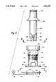
- FIG. 11is an assembly view of the apparatus of the invention with an electrical indicating means.
- FIG. 12is a partial sectional view of an alternate embodiment.
- FIG. 13is an end elevationalal view taken along line 13--13 of FIG. 12.
- FIG. 14is an enlarged partial sectional view of the positioning ring on an eye.
- FIG. 1 of the drawingsa horizontal section of the eye shows the globe of the eye resembling a sphere with an anterior bulged spherical portion 12 representing the cornea.
- the eyeis actually comprised of two somewhat modified spheres placed one in front of the other. The anterior of these two segments is the smaller more curved cornea.
- the globe of the eyeconsists of three concentric coverings enclosing the various transparent media through which the light must pass before reaching the sensitive retina.
- the outermost coveringis a fibrous protective portion, the posterior five-sixths of which is white and opaque and called the sclera 13, and sometimes referred to as the white of the eye where visible to the front.
- the anterior one-sixth of this outer layeris the transparent cornea 12.
- a middle coveringis mainly vascular and nutritive in function and is comprised of the choroid 14, ciliary body 15 and iris 17.
- the choroidgenerally functions to maintain the retina.
- the ciliary muscleis involved in suspending the lens and accommodation of the lens.
- the irisis the most anterior portion of the middle covering of the eye and is arranged in a frontal plane. It is a thin circular disc corresponding to the diaphragm of a camera, and is perforated near its center by a circular aperture called the pupil 19.
- the size of the pupilvaries to regulate the amount of light which reaches the retina. It contracts also to accommodation, which serves to sharpen the focus by diminishing spherical aberration.
- the irisdivides the space between the cornea 12 and the lens 21 into an anterior chamber 22 and posterior chamber 23.
- the innermost portion of coveringis the retina 18, consisting of nerve elements which form the true receptive portion for visual impressions.
- the retinais a part of the brain arising as an outgrowth from the fore-brain, with the optic nerve 24 serving as a fibre tract connecting the retina part of the brain with the fore-brain.
- the vitreous 26is a transparent gelatinous mass which fills the posterior four-fifths of the globe. At its sides it supports the ciliary body 16 and the retina 18. A frontal saucer-shaped depression houses the lens 21.
- the lens 21 of the eyeis a transparent bi-convex body of crystalline appearance placed between the iris 17 and vitreous 26. Its axial diameter varies markedly with accommodation.
- a ciliary zonule 27, consisting of transparent fibers passing between the ciliary body 16 and lens 21serves to hold the lens in position and enable the ciliary muscle to act on it.
- this outermost fibrous transparent coatingresembles a watch glass. Its curvature is somewhat greater than the rest of the globe and is ideally spherical in nature. However, often it is more curved in one meridian than another giving rise to astigmatism. A central third of the cornea is called the optical zone with a slight flattening taking place outwardly thereof as the cornea thickens towards it periphery. Most of the refraction of the eye takes place on the surface of the cornea.
- FIG. 2 of the drawingsthe globe of an eye is shown having a cornea 12 with a normal curvature represented by the solid line 39. If parallel rays of light 41 pass through the corneal surface 39 of FIG. 2, they are refracted by the corneal surfaces to converge eventually near the retina 18 of the eye.
- the diagram of FIG. 2discounts, for the purposes of this discussion, the refractive effect of the lens or other portions of the eye.
- the eye depicted in FIG. 2is hyperopic and thus the rays of light 41 are refracted to converge at point 42 behind the retina. If a peripheral band of pressure is applied inwardly at the chord 43 of the cornea, the walls of the cornea are caused to steepen.
- the volume of fluids within the anterior chamber 22remains constant, thus the anterior portion of the cornea, including the optical zone (inner third of the cornea) steepens in slope to form a curvature (shown in exaggeration) following the dotted line 44.
- the rays of light 41are then refracted from the steeper surface 44 at a greater angle to direct the refracted rays into focus at shorter distance, such as directly on the retina 18.
- FIG. 3shows a similar eye system to that of FIG. 2 except that the so-called normal corneal curvature of FIG. 3 causes the light rays 41 to refract into focus at a point 46 in the vitreous which is short of the retinal surface 18. This is typical of a myopic eye. If chord 43 of the cornea is expanded uniformly outwardly as shown by the arrows, the walls of the cornea are flattened. Light rays 41 refracted by the now flattened corneal surface will be refracted at a smaller angle and thus converge at a more distant point such as directly on the retina 18.
- FIG. 4a more detailed drawing of the anterior portion of the globe shows the various layers of the cornea comprising an epithelium 31.
- Epithelial cells on the surface thereoffunction to maintain transparency of the cornea. These epithelial cells are rich in glycogen, enzymes and acetylcholine and their activity regulates the corneal corpuscles and controls the transport of water and electrolytes through the lamellae of the stroma 32 of the cornea.
- An anterior limiting lamina 33is positioned between the epithelium 31 and the substantia intestinal or stroma 32 of the cornea.
- the stromais comprised of lamella having bands of fibrils parallel to each other and crossing the whole of the cornea. While most of the fibrous bands are parallel to the surface, some are oblique, especially anteriorly. The fibrous bands within alternate lamella are at a near right angle to bands in the adjacent lamella.
- a posterior limiting lamina 34is referred to as Descemet's membrane. It is a strong membrane sharply defined from the stroma and resistant to pathological processes of the cornea.
- the endothelium 36is the most posterior layer of the cornea and consists of a single layer of cells.
- the limbus 37is the transition zone between the conjunctiva 38 and sclera 13 on the one hand and the cornea 12 on the other.
- FIG. 5wherein the assembly of the basic parts of the apparatus are shown in an exploded view.
- These partscomprises a cylindrical positioning ring 50 having a resilient vacuum ring 52 extending from the bottom side of the positioning ring for contact with the eye of the patient being treated.
- a vacuum hose 54provides communication from the inside of the resilient ring 52 and a vacuum pump source means 56 as a means to retain the assembled parts upon the eye for surgical procedures herein described and to remove scarified portion of the cornea.
- a plurality of positioning pins 58are provided on the top side of the positioning ring to receive the cylindrical holding sleeve 60, the pins being adapted to be received through openings 62 in the flange portion 64.
- a visual inspection opening 66is provided for use by the surgeon.
- the exterior of the cylindrical holding sleeve 60includes a plurality of screw threads 68 along its length, the threads being a very fine pitch thread, e.g., of a pitch equal to 40 threads per inch.
- An indicia or marker 70is provided in the body of the cylindrical holding sleeve so as to provide a visual measuring point for the surgeon relative to the rotatable position of a micrometer-like guide sleeve 72 which includes interior threads to match threads 68 of the cylindrical holding sleeve.
- the guide sleeveincludes an outer knob portion 74 and indicia generally designated by the numeral 76, e.g. millimeter or micrometer like markings on the lower portion of the guide sleeve.
- the interior 78 of the cylindrical holding sleeveis adapted to rotatably receive a profiling tool 80.
- the profiling toolincludes a collar 82 which is adapted to rest upon the top surface 83 of the guide sleeve 72 for movement upwardly or downwardly therewith.
- the top end of the profiling toolcan include a knurled portion 84 for rotation and/or oscillation by the surgeon.
- At the bottom of the profiling toolare a plurality of scarifying surgically sharp knife-edge blades 86 and 88 which are retained within the body of the profiling tool 80 by pins 87, 89 and 91.
- the blades 86 and 88are retained transverse to the longitudinal axis of the profiling tool 80.
- the blades 86 and 88 as used in the inventionare of surgical steel.
- the profiling tool 80 of FIG. 5is adapted to provide a scarifying or sculpting operation upon the cornea over the top center thereof for myopia refractive error, i.e., nearsightedness, which will effectively lengthen the corneal radius of curvature as shown in FIG. 3.
- myopia refractive errori.e., nearsightedness
- the profiling tool as shown in FIG. 8is utilized, the tool having a shank 90 of similar design to tool 80 shown in FIG. 5, except that the bottom end of the tool includes a plurality of surgical steel knife-edge blades 92, 94 and 96 which are positioned transverse to the axis of the tool at an angle of approximately 30° with respect to the horizontal axis (or 60° to the vertical axis).
- the bladesare adapted to contact the outer anterior portion of the cornea in order to shorten the effective radius thereof, that is, the blades will be adapted to contact and scarify the corneal area A as shown in FIG. 2 whereas the profiling tool 80 of FIG. 5 will be adapted to sculpt or scarify the area B of FIG. 3.
- the operation of the apparatus and methods of surgeryare accomplished by first taking optical measurements of the eye as to what shape the cornea should have in order for that eye to operate in an optically correct manner, i.e., correct refractive errors.
- a kerotograph photographic image using a placido-ring targetis used.
- the photographis of reflected light from the placido rings upon a standard spherical surface of the same size as the cornea in question, creating an image in the same manner as a topographic contour map.
- the topographic survey of the eye to be correctedis made for comparison purposes and to provide the surgeon with the necessary dioptic information for correcting the refractive errors. Once this occurs, then the operation will proceed by placing the positioning ring 50 over the eye as shown in FIG.
- the size of this ringmay vary for different operations but is preferably of size wherein the resilient vacuum ring 52 will rest upon the sclera portion of the eye concentric about the cornea.
- the profiling tool 80 of FIG. 5is utilized.
- the knife-edge bladespress upon the corneal surface which becomes depressed and thus gives a larger contact surface with the blades resulting in a larger diameter of sculptured surface.
- the scarifying or sculpting actionis accentuated in proportion to the pressure between the cornea and the blade.
- the resulting effectis a lengthening of the refractive radius in that portion of the cornea under the blade.
- the corneareturns to its normal contour except that the radius over the top center thereof is now longer than it was initially. As a result, refractive light through the cornea now focuses upon the retina.
- the scarifying actionoccurs by the surgeon in incremental movement by rotating or reciprocating the guide sleeve 72 relative to cylindrical holding sleeve 60 utilizing the incremental measuring indicia 76 relative to a pointer or other indicia 70.
- the guide sleeveis graduated into 25 or 50 micrometer divisions to provide one hundredth millimeter adjustments for each marked division of rotation.
- the surgeonbegins to decide the amount of downward movement needed to achieve the required changes in the cornea by the rotation and/or oscillation of the knives.
- the rotation for a period of a few secondswill result in removal of small amounts of corneal material from the cornea.
- the toolcan be removed and/or kerotographic photographs taken to determine if the refractive error has been corrected.
- the apparatus and the surgical methodsdeal with very small increments of movement in the corneal reprofiling process, it is essential that the first contact setting be precise and accurate. Many times this can be done by visual means by the surgeon and in other instances electrical detecting means can be provided between the cornea and the tool blade to provide an exact setting of the tool which permits repeatable amounts of corneal removal.
- the profiling tool of FIGS. 9 and 10represent a modified form comprising a body 90 with an indented handle 92 and a knurled finger knob 94.
- an internal sleeve clampis comprised of scissor elements 96 and 98 which are pivoted at pin 100. The outer ends of the elements are grooved at 99 and 101 to provide a gripping action against the internal diameter of the tool guide or holding sleeve 60.
- a spring 102normally biases the blade handles 104 and 106 outward. Pinching the handles 104 and 106 inward retracts respective elements 96 and 98 so as to be able to be inserted into the cylindrical holding sleeve 60. Release of the handles causes the elements 96 and 98 to frictionally engage with the internal periphery of sleeve 60.
- FIG. 11provides an electrical indication means for the surgeon to determine the initial contact of the tool blades.
- a first contact electrode 110is removably connected with the conductive tool 90.
- a second electrodeis grounded to the patient at 112.
- the leadsare connected to a low voltage power source 114 including an indicator lamp 116.
- the profiling toolis designed to be removed and replaced without changing the depth setting of the sleeve 72.
- the amount of depth removalis about two thousandths of an inch (0.002").
- a nomogram used with a computer generated set of curves of the cornea before and after each contouring procedurepermits the surgeon to constantly monitor the amount of removal of the epithelium layer and/or in some cases portions of Bowman's layer. It has been found that the epithelium will return over the surface of the contoured portion in a period of 24 to 48 hours. However, there will be no regrowth of the Bowman's laywer which will cause the changed radius to remain. The epithelium will return and regrow to its same thickness and clarity but with a changed radius.
- FIGS. 12 and 13represent a modified form of profiling tool blade design, shown here for correcting hyperopia, but the same concept is applicable to myopia correcting tools.
- the body 120includes a plurality of radially intersecting blades 122.
- the extreme tip 124 of the sharpened end of each bladeis bent at an angle preferably of 120°.
- the bend of the edge of the bladesare in alternate directions as shown by the arrows in FIG. 13.
- FIG. 14is an enlarged view of the positioning ring 52 as positioned on an eye forming a small vacuum pocket for maintaining the ring on the eye during surgery.
Landscapes
- Health & Medical Sciences (AREA)
- Life Sciences & Earth Sciences (AREA)
- Ophthalmology & Optometry (AREA)
- Surgery (AREA)
- Veterinary Medicine (AREA)
- Biomedical Technology (AREA)
- Heart & Thoracic Surgery (AREA)
- Engineering & Computer Science (AREA)
- Animal Behavior & Ethology (AREA)
- General Health & Medical Sciences (AREA)
- Public Health (AREA)
- Nuclear Medicine, Radiotherapy & Molecular Imaging (AREA)
- Vascular Medicine (AREA)
- Medical Informatics (AREA)
- Molecular Biology (AREA)
- Eye Examination Apparatus (AREA)
- Prostheses (AREA)
- Orthopedics, Nursing, And Contraception (AREA)
- Ultra Sonic Daignosis Equipment (AREA)
- Coupling Device And Connection With Printed Circuit (AREA)
- Debugging And Monitoring (AREA)
- Laser Surgery Devices (AREA)
- Shaping Of Tube Ends By Bending Or Straightening (AREA)
- Breeding Of Plants And Reproduction By Means Of Culturing (AREA)
Abstract
Description
______________________________________ RADIUS MM BLADE- CORNEA NO. PRE-CURVE POST-CURVE DEPTH ______________________________________ 1 7.05 7.70 .002" 2 7.40 7.90 .002" 3 8.00 8.70 .002" 4 8.00 8.60 .001" 5 7.22 7.70 .001" 6 7.10 7.60 .001" ______________________________________
Claims (26)
Priority Applications (1)
| Application Number | Priority Date | Filing Date | Title |
|---|---|---|---|
| US07/979,424US5395385A (en) | 1989-12-14 | 1992-11-19 | Apparatus for surgically re-profiling the cornea |
Applications Claiming Priority (3)
| Application Number | Priority Date | Filing Date | Title |
|---|---|---|---|
| US07/450,672US5063942A (en) | 1989-12-14 | 1989-12-14 | Method for surgically re-profiling the cornea |
| US76289891A | 1991-09-19 | 1991-09-19 | |
| US07/979,424US5395385A (en) | 1989-12-14 | 1992-11-19 | Apparatus for surgically re-profiling the cornea |
Related Parent Applications (1)
| Application Number | Title | Priority Date | Filing Date |
|---|---|---|---|
| US76289891AContinuation | 1989-12-14 | 1991-09-19 |
Publications (1)
| Publication Number | Publication Date |
|---|---|
| US5395385Atrue US5395385A (en) | 1995-03-07 |
Family
ID=23789051
Family Applications (2)
| Application Number | Title | Priority Date | Filing Date |
|---|---|---|---|
| US07/450,672Expired - Fee RelatedUS5063942A (en) | 1989-12-14 | 1989-12-14 | Method for surgically re-profiling the cornea |
| US07/979,424Expired - Fee RelatedUS5395385A (en) | 1989-12-14 | 1992-11-19 | Apparatus for surgically re-profiling the cornea |
Family Applications Before (1)
| Application Number | Title | Priority Date | Filing Date |
|---|---|---|---|
| US07/450,672Expired - Fee RelatedUS5063942A (en) | 1989-12-14 | 1989-12-14 | Method for surgically re-profiling the cornea |
Country Status (17)
| Country | Link |
|---|---|
| US (2) | US5063942A (en) |
| EP (1) | EP0600859B1 (en) |
| JP (1) | JPH05503025A (en) |
| KR (1) | KR0156727B1 (en) |
| CN (1) | CN1040502C (en) |
| AT (1) | ATE180657T1 (en) |
| AU (1) | AU646657B2 (en) |
| BR (1) | BR9007915A (en) |
| CA (1) | CA2071853A1 (en) |
| DE (1) | DE69033145T2 (en) |
| FI (1) | FI922703A7 (en) |
| HU (1) | HUT64461A (en) |
| MX (1) | MX167844B (en) |
| NO (1) | NO922314L (en) |
| RU (1) | RU2094032C1 (en) |
| WO (1) | WO1991008711A1 (en) |
| ZA (1) | ZA9010063B (en) |
Cited By (43)
| Publication number | Priority date | Publication date | Assignee | Title |
|---|---|---|---|---|
| US5591185A (en)* | 1989-12-14 | 1997-01-07 | Corneal Contouring Development L.L.C. | Method and apparatus for reprofiling or smoothing the anterior or stromal cornea by scraping |
| US5624456A (en)* | 1996-02-07 | 1997-04-29 | Hellenkamp; Johann F. | Automatic surgical device for cutting a cornea |
| US5699810A (en)* | 1994-11-10 | 1997-12-23 | Pallikaris; Ioannis G. | Procedure for removal of soft eye tissue |
| RU2129853C1 (en)* | 1998-06-24 | 1999-05-10 | Межотраслевой научно-технический комплекс "Микрохирургия глаза" | Device for formation of laser radiation profile |
| US5944731A (en)* | 1997-08-05 | 1999-08-31 | Hanna; Khalil | Surgical appliance for slicing a sliver from the cornea |
| US5947943A (en)* | 1998-02-02 | 1999-09-07 | Lee; Frances Meiling | Diaper visual indicator |
| US6007553A (en)* | 1996-02-07 | 1999-12-28 | Hellenkamp; Johann F. | Automatic surgical device control assembly for cutting a cornea |
| US6030398A (en)* | 1997-05-30 | 2000-02-29 | Summit Technology, Inc. | Surgical microtomes |
| US6051009A (en)* | 1996-02-07 | 2000-04-18 | Hellenkamp; Johann F. | Automatic surgical device for cutting a cornea and a cutting blade assembly and control assembly |
| US6083236A (en)* | 1998-08-12 | 2000-07-04 | Feingold; Vladimir | Keratome method and apparatus |
| US6143010A (en)* | 1997-07-18 | 2000-11-07 | Kera Vision Inc. | Corneal vacuum centering device |
| US20030018348A1 (en)* | 2001-07-23 | 2003-01-23 | Ioannis Pallikaris | Device for separating the epithelium layer from the surface of the cornea of an eye |
| US20030134079A1 (en)* | 2001-12-20 | 2003-07-17 | Philip Bush | Method and composition for coating mat and articles produced therewith |
| US6599305B1 (en) | 1998-08-12 | 2003-07-29 | Vladimir Feingold | Intracorneal lens placement method and apparatus |
| US20030144678A1 (en)* | 1996-02-07 | 2003-07-31 | Hellenkamp Johann F. | Automatic surgical device and control assembly for cutting a cornea |
| US6610075B1 (en) | 1997-10-24 | 2003-08-26 | Becton, Dickenson And Company | Keratome with suspended stabilized blade, improved suction ring with applanator and guided engagement with keratome cutter head, automated translation of the cutter head, and blade insertion tool |
| US6626924B1 (en) | 1998-06-01 | 2003-09-30 | Peter J. Klopotek | Surgical microtomes |
| US20030220653A1 (en)* | 2000-07-18 | 2003-11-27 | Edward Perez | Methods for producing epithelial flaps on the cornea and for placement of ocular devices and lenses beneath an epithelial flap or membrane, epithelial delaminating devices, and structures of epithelium and ocular devices and lenses |
| US20040002722A1 (en)* | 2002-03-07 | 2004-01-01 | Slade Stephen G. | Ultrasonic microkeratome |
| US20040220599A1 (en)* | 2001-07-23 | 2004-11-04 | Fos Holding S.A. | Device for separating the epithelium layer from the surface of the cornea of an eye |
| US6818004B2 (en) | 2001-10-24 | 2004-11-16 | Cesar C. Carriazo | Aspherical positioning ring |
| US20040236358A1 (en)* | 2003-04-07 | 2004-11-25 | Barrile-Josephson Craig A. | Bar-link drive system for a microkeratome |
| US20040260321A1 (en)* | 2002-12-19 | 2004-12-23 | Ming-Kok Tai | Apparatus and method for separating the epithelium layer from the cornea of an eye without corneal pre-applanation |
| US20040260320A1 (en)* | 2002-12-10 | 2004-12-23 | Lisk James R. | Disposable separator for separating the epithelium layer from the cornea of an eye |
| US20050055041A1 (en)* | 2003-09-05 | 2005-03-10 | Sightrate B.V. | Device for separation of corneal epithelium |
| US20050070942A1 (en)* | 2000-07-18 | 2005-03-31 | Edward Perez | Device for lifting an epitheleal layer and placing a corrective lens beneath it |
| WO2005030102A1 (en)* | 2003-09-22 | 2005-04-07 | Tissue Engineering Refraction, Inc. | Corneal retention device or corneal stabilizing tool |
| US20050080484A1 (en)* | 2002-09-13 | 2005-04-14 | Ocular Sciences, Inc. | Devices and methods for improving vision |
| US20050103262A1 (en)* | 2001-12-20 | 2005-05-19 | Atlas Roofing Corporation | Method and composition for coating mat and articles produced therewith |
| US20070244496A1 (en)* | 1996-02-07 | 2007-10-18 | Hellenkamp Johann F | Automatic surgical device and control assembly for cutting a cornea |
| US20070265650A1 (en)* | 2001-07-23 | 2007-11-15 | Ioannis Pallikaris | Device for separating the epithelial layer from the surface of the cornea of an eye |
| US20090024117A1 (en)* | 2007-07-19 | 2009-01-22 | Avedro, Inc. | Eye therapy system |
| US20090187184A1 (en)* | 2008-01-23 | 2009-07-23 | David Muller | System and method for reshaping an eye feature |
| US20090187178A1 (en)* | 2008-01-23 | 2009-07-23 | David Muller | System and method for positioning an eye therapy device |
| US20090187173A1 (en)* | 2008-01-23 | 2009-07-23 | David Muller | System and method for reshaping an eye feature |
| US20100185192A1 (en)* | 2008-11-11 | 2010-07-22 | Avedro, Inc. | Eye therapy system |
| US20100256626A1 (en)* | 2009-04-02 | 2010-10-07 | Avedro, Inc. | Eye therapy system |
| US20100256705A1 (en)* | 2009-04-02 | 2010-10-07 | Avedro, Inc. | Eye therapy system |
| US20100280509A1 (en)* | 2009-04-02 | 2010-11-04 | Avedro, Inc. | Eye Therapy System |
| USD627885S1 (en)* | 2009-07-22 | 2010-11-23 | Brannon James K | Trephine |
| US20130035705A1 (en)* | 2010-01-27 | 2013-02-07 | Geuder Ag | Device for applying a marking to the human eye |
| US8652131B2 (en) | 2007-07-19 | 2014-02-18 | Avedro, Inc. | Eye therapy system |
| US10064642B2 (en) | 2015-03-04 | 2018-09-04 | Covidien Lp | Surgical instrument for dissecting tissue |
Families Citing this family (62)
| Publication number | Priority date | Publication date | Assignee | Title |
|---|---|---|---|---|
| US5318044A (en)* | 1989-12-14 | 1994-06-07 | Corneal Contouring, Inc. | Method and apparatus for re-profiling the cornea to correct for hyperopia |
| US5269795A (en)* | 1991-07-03 | 1993-12-14 | Arnott Eric J | Trephine device for removing anterior epithelial cells from corneal surfaces |
| AU685744B2 (en) | 1992-04-10 | 1998-01-29 | Keravision, Inc. | Corneal vacuum centering guide and dissector |
| AU721544B2 (en)* | 1992-04-10 | 2000-07-06 | Keravision, Inc. | Corneal vacuum centering guide and dissector |
| US6450641B2 (en) | 1992-06-02 | 2002-09-17 | Lasersight Technologies, Inc. | Method of corneal analysis using a checkered placido apparatus |
| USRE37504E1 (en) | 1992-12-03 | 2002-01-08 | Lasersight Technologies, Inc. | Ophthalmic surgery method using non-contact scanning laser |
| US6716210B2 (en) | 1992-12-03 | 2004-04-06 | Lasersight Technologies, Inc. | Refractive surgical laser apparatus and method |
| ATE168260T1 (en)* | 1993-05-07 | 1998-08-15 | Grieshaber & Co Ag | EYE SURGICAL DEVICE FOR Crushing and removing the lens nucleus from the eye of a living creature |
| US6175754B1 (en) | 1995-06-07 | 2001-01-16 | Keravision, Inc. | Method and apparatus for measuring corneal incisions |
| US6551307B2 (en) | 2001-03-23 | 2003-04-22 | Gholam A. Peyman | Vision correction using intrastromal pocket and flap |
| US5722971A (en)* | 1995-10-20 | 1998-03-03 | Peyman; Gholam A. | Intrastromal corneal modification |
| US6989008B2 (en) | 2001-03-23 | 2006-01-24 | Minu Llc | Adjustable ablatable inlay |
| US5964748A (en) | 1995-10-20 | 1999-10-12 | Peyman; Gholam A. | Intrastromal corneal modification |
| US6221067B1 (en) | 1995-10-20 | 2001-04-24 | Gholam A. Peyman | Corneal modification via implantation |
| US6203538B1 (en) | 1995-11-03 | 2001-03-20 | Gholam A. Peyman | Intrastromal corneal modification |
| US5997529A (en)* | 1996-10-28 | 1999-12-07 | Lasersight Technologies, Inc. | Compound astigmatic myopia or hyperopia correction by laser ablation |
| RU2161941C2 (en)* | 1996-12-25 | 2001-01-20 | Межотраслевой научно-технический комплекс "Микрохирургия глаза" | Surgical method for treating the cases of hypermetropia |
| US5792160A (en)* | 1997-01-21 | 1998-08-11 | Weiss; Richard A. | Epithelial remover tool |
| US6210169B1 (en) | 1997-01-31 | 2001-04-03 | Lasersight Technologies, Inc. | Device and method for simulating ophthalmic surgery |
| ES2136559B1 (en)* | 1997-09-04 | 2000-07-01 | Medina Puerta Antonio | DEVICE TO MODIFY THE SHAPE OF THE CORNEA. |
| US5964776A (en)* | 1997-09-24 | 1999-10-12 | Peyman; Gholam A. | Internal keratome apparatus and method for using the same to form a pocket/flap between layers of a live cornea |
| US6007202A (en) | 1997-10-23 | 1999-12-28 | Lasersight Technologies, Inc. | Eye illumination system and method |
| US6132424A (en)* | 1998-03-13 | 2000-10-17 | Lasersight Technologies Inc. | Smooth and uniform laser ablation apparatus and method |
| US6409718B1 (en) | 1998-02-03 | 2002-06-25 | Lasersight Technologies, Inc. | Device and method for correcting astigmatism by laser ablation |
| EP1173790A2 (en) | 1999-03-01 | 2002-01-23 | Boston Innovative Optics, Inc. | System and method for increasing the depth of focus of the human eye |
| US6497701B2 (en) | 1999-04-30 | 2002-12-24 | Visx, Incorporated | Method and system for ablating surfaces with partially overlapping craters having consistent curvature |
| RU2184510C2 (en)* | 1999-11-04 | 2002-07-10 | Государственное учреждение Межотраслевой научно-технический комплекс "Микрохирургия глаза" | Method for treating infantine hypermetropia |
| US6613061B1 (en)* | 2000-09-08 | 2003-09-02 | Randall J. Olson | Device for transplanting a cornea on a patient's eye |
| US8668735B2 (en) | 2000-09-12 | 2014-03-11 | Revision Optics, Inc. | Corneal implant storage and delivery devices |
| CA2421948C (en) | 2000-09-12 | 2009-12-22 | Anamed, Inc. | System for packaging and handling an implant and method of use |
| JP3628250B2 (en)* | 2000-11-17 | 2005-03-09 | 株式会社東芝 | Registration / authentication method used in a wireless communication system |
| US20050182489A1 (en)* | 2001-04-27 | 2005-08-18 | Peyman Gholam A. | Intraocular lens adapted for adjustment via laser after implantation |
| US20050222679A1 (en)* | 2001-04-27 | 2005-10-06 | Peyman Gholam A | Bifocal implant and method for altering the refractive properties of the eye |
| US20050182488A1 (en)* | 2001-04-27 | 2005-08-18 | Peyman Gholam A. | Implant and method for altering the refractive properties of the eye |
| US6786926B2 (en)* | 2001-11-09 | 2004-09-07 | Minu, L.L.C. | Method and apparatus for alignment of intracorneal inlay |
| US20050046794A1 (en) | 2003-06-17 | 2005-03-03 | Silvestrini Thomas A. | Method and apparatus for aligning a mask with the visual axis of an eye |
| AU2004268582A1 (en)* | 2003-08-21 | 2005-03-10 | Revision Optics, Inc. | Method for keratophakia surgery |
| US8057541B2 (en) | 2006-02-24 | 2011-11-15 | Revision Optics, Inc. | Method of using small diameter intracorneal inlays to treat visual impairment |
| US10835371B2 (en) | 2004-04-30 | 2020-11-17 | Rvo 2.0, Inc. | Small diameter corneal inlay methods |
| US7776086B2 (en) | 2004-04-30 | 2010-08-17 | Revision Optics, Inc. | Aspherical corneal implant |
| US7744614B2 (en)* | 2005-06-15 | 2010-06-29 | Krishna Imports, Incorporated | Corneal excision or scoring device |
| USD546452S1 (en) | 2005-06-15 | 2007-07-10 | Krishna Imports, Incorporated | Excision device |
| US10555805B2 (en) | 2006-02-24 | 2020-02-11 | Rvo 2.0, Inc. | Anterior corneal shapes and methods of providing the shapes |
| US9549848B2 (en) | 2007-03-28 | 2017-01-24 | Revision Optics, Inc. | Corneal implant inserters and methods of use |
| US8162953B2 (en) | 2007-03-28 | 2012-04-24 | Revision Optics, Inc. | Insertion system for corneal implants |
| US9271828B2 (en) | 2007-03-28 | 2016-03-01 | Revision Optics, Inc. | Corneal implant retaining devices and methods of use |
| RU2363432C2 (en)* | 2007-10-10 | 2009-08-10 | Федеральное государственное учреждение "Межотраслевой научно-технический комплекс "Микрохирургия глаза" имени академика С.Н. Федорова Федерального агентства по высокотехнологичной медицинской помощи" | Method of surgical correction of hypermetropia and hypermetropic astigmia on thin cornea in children with anisometropia |
| JP2011516180A (en) | 2008-04-04 | 2011-05-26 | レヴィジオン・オプティックス・インコーポレーテッド | Corneal inlay design and method for correcting vision |
| US9539143B2 (en) | 2008-04-04 | 2017-01-10 | Revision Optics, Inc. | Methods of correcting vision |
| RU2419402C2 (en)* | 2009-04-13 | 2011-05-27 | Сергей Игоревич Анисимов | Method of treating refraction abnormalities by impact of ultraviolet radiation and device for its realisation |
| US9408746B2 (en) | 2010-03-31 | 2016-08-09 | Ocuject, Llc | Device and method for intraocular drug delivery |
| US8469948B2 (en) | 2010-08-23 | 2013-06-25 | Revision Optics, Inc. | Methods and devices for forming corneal channels |
| WO2013059813A1 (en) | 2011-10-21 | 2013-04-25 | Revision Optics, Inc. | Corneal implant storage and delivery devices |
| JP6046160B2 (en) | 2011-12-02 | 2016-12-14 | アキュフォーカス・インコーポレーテッド | Ophthalmic mask with selective spectral transmission |
| US9504603B2 (en) | 2012-04-02 | 2016-11-29 | Ocuject, Llc | Intraocular delivery devices and methods therefor |
| US9421129B2 (en) | 2012-04-02 | 2016-08-23 | Ocuject, Llc | Intraocular delivery devices and methods therefor |
| RU2536047C2 (en)* | 2012-10-24 | 2014-12-20 | Александр Николаевич Епихин | Method for intraoperative correction of corneal shape in cataract extraction using small and very small incision technique and implantation of intraocular lens through self-sealing tunnel incision |
| US9204962B2 (en) | 2013-03-13 | 2015-12-08 | Acufocus, Inc. | In situ adjustable optical mask |
| US9427922B2 (en) | 2013-03-14 | 2016-08-30 | Acufocus, Inc. | Process for manufacturing an intraocular lens with an embedded mask |
| RU2531471C1 (en)* | 2013-07-04 | 2014-10-20 | федеральное государственное бюджетное учреждение "Межотраслевой научно-технический комплекс "Микрохирургия глаза" имени академика С.Н. Федорова" Министерства здравоохранения Российской Федерации | Instrument for graduated scarification of corneal epithelium |
| AU2015385773A1 (en) | 2015-03-12 | 2017-10-05 | Revision Optics, Inc. | Methods of correcting vision |
| RU2602221C1 (en)* | 2015-06-18 | 2016-11-10 | федеральное государственное бюджетное учреждение "Межотраслевой научно-технический комплекс "Микрохирургия глаза" имени академика С.Н. Федорова" Министерства здравоохранения Российской Федерации | Method of treating keratoconus and tool for its implementation |
Citations (12)
| Publication number | Priority date | Publication date | Assignee | Title |
|---|---|---|---|---|
| US2249906A (en)* | 1938-09-03 | 1941-07-22 | Ramon Castroviejo | Surgical device |
| US2480737A (en)* | 1948-03-08 | 1949-08-30 | Jayle Gaetan Jean-Edward | Cutting instrument particularly useful in connection with corneal grafting |
| US4417579A (en)* | 1982-04-16 | 1983-11-29 | Moskovsky Nauchno-Issledovatelsky Institut Mikrokhirurgii Glaza | Device for marking out the cornea in ophthalmosurgical operations |
| US4423728A (en)* | 1982-02-26 | 1984-01-03 | Lieberman David M | Cam-guided trephine |
| US4515157A (en)* | 1982-07-28 | 1985-05-07 | Moskovsky Nauchno-Issledovatelsky Institut Mikrokhirurgii Glaza | Corneal incision marker |
| US4526171A (en)* | 1980-01-15 | 1985-07-02 | Schachar Ronald A | Cornea incision device |
| US4619259A (en)* | 1980-05-09 | 1986-10-28 | Graybill Walter R | Ophthalmic surgery tool |
| US4665914A (en)* | 1985-12-27 | 1987-05-19 | Emanuel Tanne | Automatic corneal surgery system |
| US4739761A (en)* | 1986-06-26 | 1988-04-26 | Grandon Stanley C | Cornea marker |
| US4763651A (en)* | 1984-11-08 | 1988-08-16 | Allergan, Inc. | Trephine and method |
| US4834748A (en)* | 1987-09-29 | 1989-05-30 | Allergan, Inc. | Method and apparatus for removing corneal tissue |
| US4997437A (en)* | 1987-08-10 | 1991-03-05 | Grieshaber Hans R | Apparatus for the surgical correction of ametropia of one or both eyes of living beings |
Family Cites Families (19)
| Publication number | Priority date | Publication date | Assignee | Title |
|---|---|---|---|---|
| US3074407A (en)* | 1956-09-17 | 1963-01-22 | Marguerite Barr Moon Eye Res F | Surgical devices for keratoplasty and methods thereof |
| BE630556A (en)* | 1962-04-03 | |||
| US3976077A (en)* | 1975-02-03 | 1976-08-24 | Kerfoot Jr Franklin W | Eye surgery device |
| US4173980A (en)* | 1977-02-25 | 1979-11-13 | Curtin Brian J | Corneal resurfacing apparatus and method |
| US4688570A (en)* | 1981-03-09 | 1987-08-25 | The Regents Of The University Of California | Ophthalmologic surgical instrument |
| US4381007A (en)* | 1981-04-30 | 1983-04-26 | The United States Of America As Represented By The United States Department Of Energy | Multipolar corneal-shaping electrode with flexible removable skirt |
| US4490022A (en)* | 1982-01-04 | 1984-12-25 | Reynolds Alvin E | Apparatus for corneal corrective techniques |
| US4729372A (en)* | 1983-11-17 | 1988-03-08 | Lri L.P. | Apparatus for performing ophthalmic laser surgery |
| US4665913A (en)* | 1983-11-17 | 1987-05-19 | Lri L.P. | Method for ophthalmological surgery |
| US4770172A (en)* | 1983-11-17 | 1988-09-13 | Lri L.P. | Method of laser-sculpture of the optically used portion of the cornea |
| US4718418A (en)* | 1983-11-17 | 1988-01-12 | Lri L.P. | Apparatus for ophthalmological surgery |
| DE3433581C2 (en)* | 1984-09-13 | 1986-08-07 | Fa. Carl Zeiss, 7920 Heidenheim | Device for laminating, refractive corneal surgery |
| US4750491A (en)* | 1984-11-08 | 1988-06-14 | Allergan, Inc. | Trephine and method |
| FR2595243B3 (en)* | 1986-03-06 | 1988-07-08 | Khalil Hanna | KNIFE FOR SURGERY OF THE ANTERIOR EYE SEGMENT |
| US4724522A (en)* | 1986-05-27 | 1988-02-09 | Belgorod Barry M | Method and apparatus for modification of corneal refractive properties |
| US4838266A (en)* | 1986-09-08 | 1989-06-13 | Koziol Jeffrey E | Lens shaping device using a laser attenuator |
| US4840175A (en)* | 1986-12-24 | 1989-06-20 | Peyman Gholam A | Method for modifying corneal curvature |
| DE3707004A1 (en)* | 1987-03-05 | 1988-09-15 | Krumeich Joerg H | CUTTER FOR CUTTING A CIRCULAR CORNEAL DISC |
| US4798204A (en)* | 1987-05-13 | 1989-01-17 | Lri L.P. | Method of laser-sculpture of the optically used portion of the cornea |
- 1989
- 1989-12-14USUS07/450,672patent/US5063942A/ennot_activeExpired - Fee Related
- 1990
- 1990-12-12AUAU71556/91Apatent/AU646657B2/ennot_activeCeased
- 1990-12-12CACA002071853Apatent/CA2071853A1/ennot_activeAbandoned
- 1990-12-12RUSU905052732Apatent/RU2094032C1/enactive
- 1990-12-12ATAT91902435Tpatent/ATE180657T1/ennot_activeIP Right Cessation
- 1990-12-12BRBR909007915Apatent/BR9007915A/ennot_activeIP Right Cessation
- 1990-12-12WOPCT/US1990/007406patent/WO1991008711A1/enactiveIP Right Grant
- 1990-12-12FIFI922703Apatent/FI922703A7/ennot_activeApplication Discontinuation
- 1990-12-12DEDE69033145Tpatent/DE69033145T2/ennot_activeExpired - Fee Related
- 1990-12-12JPJP91502814Apatent/JPH05503025A/enactivePending
- 1990-12-12EPEP91902435Apatent/EP0600859B1/ennot_activeExpired - Lifetime
- 1990-12-12HUHU9201978Apatent/HUT64461A/enunknown
- 1990-12-12KRKR1019920701415Apatent/KR0156727B1/ennot_activeExpired - Fee Related
- 1990-12-14MXMX023746Apatent/MX167844B/enunknown
- 1990-12-14ZAZA9010063Apatent/ZA9010063B/enunknown
- 1990-12-14CNCN90110433Apatent/CN1040502C/ennot_activeExpired - Fee Related
- 1992
- 1992-06-12NONO92922314Apatent/NO922314L/enunknown
- 1992-11-19USUS07/979,424patent/US5395385A/ennot_activeExpired - Fee Related
Patent Citations (12)
| Publication number | Priority date | Publication date | Assignee | Title |
|---|---|---|---|---|
| US2249906A (en)* | 1938-09-03 | 1941-07-22 | Ramon Castroviejo | Surgical device |
| US2480737A (en)* | 1948-03-08 | 1949-08-30 | Jayle Gaetan Jean-Edward | Cutting instrument particularly useful in connection with corneal grafting |
| US4526171A (en)* | 1980-01-15 | 1985-07-02 | Schachar Ronald A | Cornea incision device |
| US4619259A (en)* | 1980-05-09 | 1986-10-28 | Graybill Walter R | Ophthalmic surgery tool |
| US4423728A (en)* | 1982-02-26 | 1984-01-03 | Lieberman David M | Cam-guided trephine |
| US4417579A (en)* | 1982-04-16 | 1983-11-29 | Moskovsky Nauchno-Issledovatelsky Institut Mikrokhirurgii Glaza | Device for marking out the cornea in ophthalmosurgical operations |
| US4515157A (en)* | 1982-07-28 | 1985-05-07 | Moskovsky Nauchno-Issledovatelsky Institut Mikrokhirurgii Glaza | Corneal incision marker |
| US4763651A (en)* | 1984-11-08 | 1988-08-16 | Allergan, Inc. | Trephine and method |
| US4665914A (en)* | 1985-12-27 | 1987-05-19 | Emanuel Tanne | Automatic corneal surgery system |
| US4739761A (en)* | 1986-06-26 | 1988-04-26 | Grandon Stanley C | Cornea marker |
| US4997437A (en)* | 1987-08-10 | 1991-03-05 | Grieshaber Hans R | Apparatus for the surgical correction of ametropia of one or both eyes of living beings |
| US4834748A (en)* | 1987-09-29 | 1989-05-30 | Allergan, Inc. | Method and apparatus for removing corneal tissue |
Cited By (72)
| Publication number | Priority date | Publication date | Assignee | Title |
|---|---|---|---|---|
| US5591185A (en)* | 1989-12-14 | 1997-01-07 | Corneal Contouring Development L.L.C. | Method and apparatus for reprofiling or smoothing the anterior or stromal cornea by scraping |
| US5699810A (en)* | 1994-11-10 | 1997-12-23 | Pallikaris; Ioannis G. | Procedure for removal of soft eye tissue |
| US6296649B1 (en) | 1996-02-07 | 2001-10-02 | Johann F. Hellenkamp | Automatic surgical device for cutting a cornea |
| US5624456A (en)* | 1996-02-07 | 1997-04-29 | Hellenkamp; Johann F. | Automatic surgical device for cutting a cornea |
| US6605099B1 (en) | 1996-02-07 | 2003-08-12 | Johann F. Hellenkamp | Automatic surgical device and control assembly for cutting a cornea |
| US20030144678A1 (en)* | 1996-02-07 | 2003-07-31 | Hellenkamp Johann F. | Automatic surgical device and control assembly for cutting a cornea |
| US6007553A (en)* | 1996-02-07 | 1999-12-28 | Hellenkamp; Johann F. | Automatic surgical device control assembly for cutting a cornea |
| US6527788B1 (en) | 1996-02-07 | 2003-03-04 | Johann F. Hellenkamp | Automatic surgical device for cutting a cornea and a cutting blade assembly and control assembly therefor |
| US6051009A (en)* | 1996-02-07 | 2000-04-18 | Hellenkamp; Johann F. | Automatic surgical device for cutting a cornea and a cutting blade assembly and control assembly |
| US20070244496A1 (en)* | 1996-02-07 | 2007-10-18 | Hellenkamp Johann F | Automatic surgical device and control assembly for cutting a cornea |
| US7166117B2 (en) | 1996-02-07 | 2007-01-23 | Hellenkamp Johann F | Automatic surgical device and control assembly for cutting a cornea |
| US6099541A (en)* | 1997-05-30 | 2000-08-08 | Summit Technology, Inc. | Surgical microtomes |
| US6030398A (en)* | 1997-05-30 | 2000-02-29 | Summit Technology, Inc. | Surgical microtomes |
| US6143010A (en)* | 1997-07-18 | 2000-11-07 | Kera Vision Inc. | Corneal vacuum centering device |
| US5944731A (en)* | 1997-08-05 | 1999-08-31 | Hanna; Khalil | Surgical appliance for slicing a sliver from the cornea |
| US7056327B2 (en) | 1997-10-24 | 2006-06-06 | Becton, Dickinson & Company | Keratome with suspended stabilized blade, applanator and guided engagement with keratome cutter head |
| US20040010277A1 (en)* | 1997-10-24 | 2004-01-15 | Levesque Gaston J. | Keratome with suspended stabilized blade, improved suction ring with applanator and guided engagement with keratome cutter head, automated translation of the cutter head, and blade insertion tool |
| US6610075B1 (en) | 1997-10-24 | 2003-08-26 | Becton, Dickenson And Company | Keratome with suspended stabilized blade, improved suction ring with applanator and guided engagement with keratome cutter head, automated translation of the cutter head, and blade insertion tool |
| US5947943A (en)* | 1998-02-02 | 1999-09-07 | Lee; Frances Meiling | Diaper visual indicator |
| US6626924B1 (en) | 1998-06-01 | 2003-09-30 | Peter J. Klopotek | Surgical microtomes |
| RU2129853C1 (en)* | 1998-06-24 | 1999-05-10 | Межотраслевой научно-технический комплекс "Микрохирургия глаза" | Device for formation of laser radiation profile |
| US6083236A (en)* | 1998-08-12 | 2000-07-04 | Feingold; Vladimir | Keratome method and apparatus |
| US6623497B1 (en) | 1998-08-12 | 2003-09-23 | Vladimir Feingold | Keratome without applanator |
| US6599305B1 (en) | 1998-08-12 | 2003-07-29 | Vladimir Feingold | Intracorneal lens placement method and apparatus |
| US20030220653A1 (en)* | 2000-07-18 | 2003-11-27 | Edward Perez | Methods for producing epithelial flaps on the cornea and for placement of ocular devices and lenses beneath an epithelial flap or membrane, epithelial delaminating devices, and structures of epithelium and ocular devices and lenses |
| US20050070942A1 (en)* | 2000-07-18 | 2005-03-31 | Edward Perez | Device for lifting an epitheleal layer and placing a corrective lens beneath it |
| US7497866B2 (en) | 2000-07-18 | 2009-03-03 | Tissue Engineering Refraction Inc. | Methods for producing epithelial flaps on the cornea and for placement of ocular devices and lenses beneath an epithelial flap or membrane, epithelial delaminating devices, and structures of epithelium and ocular devices and lenses |
| US20040220599A1 (en)* | 2001-07-23 | 2004-11-04 | Fos Holding S.A. | Device for separating the epithelium layer from the surface of the cornea of an eye |
| US20040167555A1 (en)* | 2001-07-23 | 2004-08-26 | Fos Holding S.A. | Device for separating the epithelium layer from the surface of the cornea of an eye |
| US20070265650A1 (en)* | 2001-07-23 | 2007-11-15 | Ioannis Pallikaris | Device for separating the epithelial layer from the surface of the cornea of an eye |
| US20030018347A1 (en)* | 2001-07-23 | 2003-01-23 | Ioannis Pallikaris | Device for separating the epithelium layer from the surface of the cornea of an eye |
| US20030018348A1 (en)* | 2001-07-23 | 2003-01-23 | Ioannis Pallikaris | Device for separating the epithelium layer from the surface of the cornea of an eye |
| US7156859B2 (en) | 2001-07-23 | 2007-01-02 | Fos Holding S.A. | Device for separating the epithelium layer from the surface of the cornea of an eye |
| US7708750B2 (en) | 2001-07-23 | 2010-05-04 | Fos Holdings S.A. | Device for separating the epithelium layer from the surface of the cornea of an eye |
| US20050288696A1 (en)* | 2001-07-23 | 2005-12-29 | Pallikaris Ioannis G | Device for separating the epithelial layer from the surface of the cornea of an eye |
| US7004953B2 (en)* | 2001-07-23 | 2006-02-28 | Fos Holding S.A. | Device for separating the epithelium layer from the surface of the cornea of an eye |
| US6818004B2 (en) | 2001-10-24 | 2004-11-16 | Cesar C. Carriazo | Aspherical positioning ring |
| US20100087114A1 (en)* | 2001-12-20 | 2010-04-08 | Atlas Roofing Corporation | Method and composition for coating mat and articles produced therewith |
| US20030134079A1 (en)* | 2001-12-20 | 2003-07-17 | Philip Bush | Method and composition for coating mat and articles produced therewith |
| US20070042657A1 (en)* | 2001-12-20 | 2007-02-22 | Atlas Roofing Corp. | Method and composition for coating mat and articles produced therewith |
| US20050103262A1 (en)* | 2001-12-20 | 2005-05-19 | Atlas Roofing Corporation | Method and composition for coating mat and articles produced therewith |
| AU2003207603B2 (en)* | 2002-01-17 | 2008-04-03 | Edward Perez | Methods for producing epithelial flaps on the cornea and for placement of ocular devices and lenses beneath an epithelial flap or membrane, epithelial delaminating devices, and structures of epithelium and ocular devices and lenses |
| CN1310629C (en)* | 2002-01-17 | 2007-04-18 | 爱德华·佩雷兹 | Epithelial layering device for preparation of epithelial flaps on the cornea and placement of intraocular devices and lenses under the epithelial flaps |
| WO2003061518A3 (en)* | 2002-01-17 | 2004-07-29 | Edward Perez | Methods for producing epithelial flaps on the cornea and for placement of ocular devices and lenses beneath an epithelial flap or membrane, epithelial delaminating devices, and structures of epithelium and ocular devices and lenses |
| US20040002722A1 (en)* | 2002-03-07 | 2004-01-01 | Slade Stephen G. | Ultrasonic microkeratome |
| US20050080484A1 (en)* | 2002-09-13 | 2005-04-14 | Ocular Sciences, Inc. | Devices and methods for improving vision |
| US7828844B2 (en)* | 2002-09-13 | 2010-11-09 | Forsight Labs, Llc | Inserting lenses into corneal epithelial pockets to improve vision |
| US20040260320A1 (en)* | 2002-12-10 | 2004-12-23 | Lisk James R. | Disposable separator for separating the epithelium layer from the cornea of an eye |
| US20040260321A1 (en)* | 2002-12-19 | 2004-12-23 | Ming-Kok Tai | Apparatus and method for separating the epithelium layer from the cornea of an eye without corneal pre-applanation |
| US7780689B2 (en) | 2003-04-07 | 2010-08-24 | Technolas Perfect Vision Gmbh | Bar-link drive system for a microkeratome |
| US20040236358A1 (en)* | 2003-04-07 | 2004-11-25 | Barrile-Josephson Craig A. | Bar-link drive system for a microkeratome |
| US20050055041A1 (en)* | 2003-09-05 | 2005-03-10 | Sightrate B.V. | Device for separation of corneal epithelium |
| US20060247660A1 (en)* | 2003-09-22 | 2006-11-02 | Edward Perez | Corneal retention or stabilizing tool |
| WO2005030102A1 (en)* | 2003-09-22 | 2005-04-07 | Tissue Engineering Refraction, Inc. | Corneal retention device or corneal stabilizing tool |
| US8992516B2 (en) | 2007-07-19 | 2015-03-31 | Avedro, Inc. | Eye therapy system |
| US8652131B2 (en) | 2007-07-19 | 2014-02-18 | Avedro, Inc. | Eye therapy system |
| US20090024117A1 (en)* | 2007-07-19 | 2009-01-22 | Avedro, Inc. | Eye therapy system |
| US8409189B2 (en)* | 2008-01-23 | 2013-04-02 | Avedro, Inc. | System and method for reshaping an eye feature |
| US20090187173A1 (en)* | 2008-01-23 | 2009-07-23 | David Muller | System and method for reshaping an eye feature |
| US20090187184A1 (en)* | 2008-01-23 | 2009-07-23 | David Muller | System and method for reshaping an eye feature |
| US20090187178A1 (en)* | 2008-01-23 | 2009-07-23 | David Muller | System and method for positioning an eye therapy device |
| US8469952B2 (en)* | 2008-01-23 | 2013-06-25 | Avedro, Inc. | System and method for positioning an eye therapy device |
| US20100185192A1 (en)* | 2008-11-11 | 2010-07-22 | Avedro, Inc. | Eye therapy system |
| US8882757B2 (en) | 2008-11-11 | 2014-11-11 | Avedro, Inc. | Eye therapy system |
| US20100256626A1 (en)* | 2009-04-02 | 2010-10-07 | Avedro, Inc. | Eye therapy system |
| US20100280509A1 (en)* | 2009-04-02 | 2010-11-04 | Avedro, Inc. | Eye Therapy System |
| US8712536B2 (en) | 2009-04-02 | 2014-04-29 | Avedro, Inc. | Eye therapy system |
| US20100256705A1 (en)* | 2009-04-02 | 2010-10-07 | Avedro, Inc. | Eye therapy system |
| USD627885S1 (en)* | 2009-07-22 | 2010-11-23 | Brannon James K | Trephine |
| US20130035705A1 (en)* | 2010-01-27 | 2013-02-07 | Geuder Ag | Device for applying a marking to the human eye |
| US9149390B2 (en)* | 2010-01-27 | 2015-10-06 | Geuder Ag | Device for applying a marking to the human eye |
| US10064642B2 (en) | 2015-03-04 | 2018-09-04 | Covidien Lp | Surgical instrument for dissecting tissue |
Also Published As
| Publication number | Publication date |
|---|---|
| KR920702972A (en) | 1992-12-17 |
| FI922703A0 (en) | 1992-06-11 |
| DE69033145T2 (en) | 1999-12-09 |
| DE69033145D1 (en) | 1999-07-08 |
| HUT64461A (en) | 1994-01-28 |
| ATE180657T1 (en) | 1999-06-15 |
| AU646657B2 (en) | 1994-03-03 |
| MX167844B (en) | 1993-04-15 |
| AU7155691A (en) | 1991-07-18 |
| JPH05503025A (en) | 1993-05-27 |
| KR0156727B1 (en) | 1998-12-15 |
| WO1991008711A1 (en) | 1991-06-27 |
| CN1053181A (en) | 1991-07-24 |
| ZA9010063B (en) | 1991-11-27 |
| FI922703A7 (en) | 1992-06-11 |
| NO922314L (en) | 1992-08-10 |
| CN1040502C (en) | 1998-11-04 |
| EP0600859A1 (en) | 1994-06-15 |
| BR9007915A (en) | 1992-11-24 |
| EP0600859B1 (en) | 1999-06-02 |
| EP0600859A4 (en) | 1993-05-05 |
| RU2094032C1 (en) | 1997-10-27 |
| HU9201978D0 (en) | 1992-09-28 |
| US5063942A (en) | 1991-11-12 |
| NO922314D0 (en) | 1992-06-12 |
| CA2071853A1 (en) | 1991-06-15 |
Similar Documents
| Publication | Publication Date | Title |
|---|---|---|
| US5395385A (en) | Apparatus for surgically re-profiling the cornea | |
| EP0680298B1 (en) | Apparatus for re-profiling the cornea to correct for hyperopia | |
| US5368604A (en) | Method and apparatus for surgically profiling the cornea using vacuum | |
| US5591185A (en) | Method and apparatus for reprofiling or smoothing the anterior or stromal cornea by scraping | |
| US5395356A (en) | Correction of presbyopia by photorefractive keratectomy | |
| US4961744A (en) | Holder for inserting corneal curvature adjustable ring | |
| US5423801A (en) | Laser corneal surgery | |
| US5188125A (en) | Method for corneal curvature adjustment | |
| US4721379A (en) | Apparatus for analysis and correction of abnormal refractive errors of the eye | |
| US5312424A (en) | Conreal curvature adjustment ring | |
| US5505722A (en) | Corneal curvature adjusting ring | |
| JPS6253650A (en) | Opthalmic operation method and apparatus | |
| US6051023A (en) | Corneal curvature adjustment ring and apparatus for making a cornea | |
| WO1993025166A1 (en) | Correction of presbyopia by photorefractive keratectomy | |
| EP0551439B1 (en) | Apparatus for surgically profiling the cornea using vacuum | |
| EP0398874B1 (en) | Corneal curvature adjustment ring |
Legal Events
| Date | Code | Title | Description |
|---|---|---|---|
| AS | Assignment | Owner name:CORNEAL CONTOURING DEVELOPMENT, L.L.C., OKLAHOMA Free format text:ASSIGNMENT OF ASSIGNORS INTEREST;ASSIGNOR:CORNEAL CONTOURING, INC.;REEL/FRAME:007185/0372 Effective date:19941013 | |
| FEPP | Fee payment procedure | Free format text:PAT HOLDER CLAIMS SMALL ENTITY STATUS - SMALL BUSINESS (ORIGINAL EVENT CODE: SM02); ENTITY STATUS OF PATENT OWNER: SMALL ENTITY | |
| AS | Assignment | Owner name:PREMIER LASER SYSTEMS, INC., CALIFORNIA Free format text:SECURITY INTEREST;ASSIGNOR:CORNEAL CONTOURING DEVELOPMENT, L.L.C.;REEL/FRAME:008995/0407 Effective date:19980115 | |
| AS | Assignment | Owner name:PREMIER LASER SYSTEMS, INC., CALIFORNIA Free format text:ASSIGNMENT OF ASSIGNORS INTEREST;ASSIGNOR:CORNEAL CONTURING DEVELOPMENT, L.L.C.;REEL/FRAME:009267/0820 Effective date:19980115 | |
| FPAY | Fee payment | Year of fee payment:4 | |
| AS | Assignment | Owner name:STRONG RIVER INVESTMENTS, INC., NEW YORK Free format text:ASSIGNMENT OF ASSIGNORS INTEREST;ASSIGNOR:PREMIER LASER SYSTEMS, INC.;REEL/FRAME:009798/0128 Effective date:19990517 Owner name:HERKIMER L.L.C., CAYMAN ISLANDS Free format text:ASSIGNMENT OF ASSIGNORS INTEREST;ASSIGNOR:PREMIER LASER SYSTEMS, INC.;REEL/FRAME:009798/0128 Effective date:19990517 | |
| AS | Assignment | Owner name:PREMIER LASER SYSTEMS, INC., CALIFORNIA Free format text:CONSENT AND RELEASE OF COLLATERAL;ASSIGNORS:STRONG RIVER INVESTMENTS, INC.;HERKIMER LLC;REEL/FRAME:010859/0001 Effective date:20000307 | |
| AS | Assignment | Owner name:CORNEAL CONTOURING DEVELOPMENT, L.L.C., OKLAHOMA Free format text:ASSIGNMENT OF ASSIGNORS INTEREST;ASSIGNOR:PREMIER LASER SYSTEMS, INC.;REEL/FRAME:011137/0195 Effective date:20000725 | |
| REMI | Maintenance fee reminder mailed | ||
| LAPS | Lapse for failure to pay maintenance fees | ||
| STCH | Information on status: patent discontinuation | Free format text:PATENT EXPIRED DUE TO NONPAYMENT OF MAINTENANCE FEES UNDER 37 CFR 1.362 | |
| FP | Lapsed due to failure to pay maintenance fee | Effective date:20030307 |