US5395370A - Vertebral compression clamp for surgical repair to damage to the spine - Google Patents
Vertebral compression clamp for surgical repair to damage to the spineDownload PDFInfo
- Publication number
- US5395370A US5395370AUS07/962,265US96226592AUS5395370AUS 5395370 AUS5395370 AUS 5395370AUS 96226592 AUS96226592 AUS 96226592AUS 5395370 AUS5395370 AUS 5395370A
- Authority
- US
- United States
- Prior art keywords
- threaded
- bore
- threaded spindle
- clamp jaws
- implant according
- Prior art date
- Legal status (The legal status is an assumption and is not a legal conclusion. Google has not performed a legal analysis and makes no representation as to the accuracy of the status listed.)
- Expired - Lifetime
Links
- 230000006835compressionEffects0.000titleclaimsabstractdescription29
- 238000007906compressionMethods0.000titleclaimsabstractdescription29
- 230000006378damageEffects0.000titleclaimsabstractdescription6
- 230000008439repair processEffects0.000titleclaimsabstractdescription4
- 239000007943implantSubstances0.000claimsabstractdescription27
- 210000000078clawAnatomy0.000claimsdescription17
- 238000002513implantationMethods0.000abstractdescription2
- 208000002847Surgical WoundDiseases0.000description4
- 230000008901benefitEffects0.000description4
- 238000003780insertionMethods0.000description2
- 230000037431insertionEffects0.000description2
- 230000009467reductionEffects0.000description2
- 206010041569spinal fractureDiseases0.000description2
- 206010047626Vitamin D DeficiencyDiseases0.000description1
- 208000027418Wounds and injuryDiseases0.000description1
- 230000008859changeEffects0.000description1
- 230000008602contractionEffects0.000description1
- 230000007547defectEffects0.000description1
- 201000010099diseaseDiseases0.000description1
- 208000037265diseases, disorders, signs and symptomsDiseases0.000description1
- 239000003814drugSubstances0.000description1
- 230000000694effectsEffects0.000description1
- 230000002349favourable effectEffects0.000description1
- 208000014674injuryDiseases0.000description1
- 230000009245menopauseEffects0.000description1
- 239000002184metalSubstances0.000description1
- 230000001575pathological effectEffects0.000description1
- 230000000149penetrating effectEffects0.000description1
- 230000001144postural effectEffects0.000description1
- 238000007493shaping processMethods0.000description1
- 230000000472traumatic effectEffects0.000description1
Images


Classifications
- A—HUMAN NECESSITIES
- A61—MEDICAL OR VETERINARY SCIENCE; HYGIENE
- A61B—DIAGNOSIS; SURGERY; IDENTIFICATION
- A61B17/00—Surgical instruments, devices or methods
- A61B17/56—Surgical instruments or methods for treatment of bones or joints; Devices specially adapted therefor
- A61B17/58—Surgical instruments or methods for treatment of bones or joints; Devices specially adapted therefor for osteosynthesis, e.g. bone plates, screws or setting implements
- A61B17/68—Internal fixation devices, including fasteners and spinal fixators, even if a part thereof projects from the skin
- A61B17/70—Spinal positioners or stabilisers, e.g. stabilisers comprising fluid filler in an implant
- A61B17/7001—Screws or hooks combined with longitudinal elements which do not contact vertebrae
- A61B17/7035—Screws or hooks, wherein a rod-clamping part and a bone-anchoring part can pivot relative to each other
- A61B17/704—Screws or hooks, wherein a rod-clamping part and a bone-anchoring part can pivot relative to each other the longitudinal element passing through a ball-joint in the screw head
- A—HUMAN NECESSITIES
- A61—MEDICAL OR VETERINARY SCIENCE; HYGIENE
- A61B—DIAGNOSIS; SURGERY; IDENTIFICATION
- A61B17/00—Surgical instruments, devices or methods
- A61B17/56—Surgical instruments or methods for treatment of bones or joints; Devices specially adapted therefor
- A61B17/58—Surgical instruments or methods for treatment of bones or joints; Devices specially adapted therefor for osteosynthesis, e.g. bone plates, screws or setting implements
- A61B17/68—Internal fixation devices, including fasteners and spinal fixators, even if a part thereof projects from the skin
- A61B17/70—Spinal positioners or stabilisers, e.g. stabilisers comprising fluid filler in an implant
- A61B17/7001—Screws or hooks combined with longitudinal elements which do not contact vertebrae
- A61B17/7002—Longitudinal elements, e.g. rods
- A61B17/7004—Longitudinal elements, e.g. rods with a cross-section which varies along its length
- A61B17/7005—Parts of the longitudinal elements, e.g. their ends, being specially adapted to fit in the screw or hook heads
- A—HUMAN NECESSITIES
- A61—MEDICAL OR VETERINARY SCIENCE; HYGIENE
- A61B—DIAGNOSIS; SURGERY; IDENTIFICATION
- A61B17/00—Surgical instruments, devices or methods
- A61B17/56—Surgical instruments or methods for treatment of bones or joints; Devices specially adapted therefor
- A61B17/58—Surgical instruments or methods for treatment of bones or joints; Devices specially adapted therefor for osteosynthesis, e.g. bone plates, screws or setting implements
- A61B17/68—Internal fixation devices, including fasteners and spinal fixators, even if a part thereof projects from the skin
- A61B17/70—Spinal positioners or stabilisers, e.g. stabilisers comprising fluid filler in an implant
- A61B17/7001—Screws or hooks combined with longitudinal elements which do not contact vertebrae
- A61B17/7002—Longitudinal elements, e.g. rods
- A61B17/7014—Longitudinal elements, e.g. rods with means for adjusting the distance between two screws or hooks
- A—HUMAN NECESSITIES
- A61—MEDICAL OR VETERINARY SCIENCE; HYGIENE
- A61B—DIAGNOSIS; SURGERY; IDENTIFICATION
- A61B17/00—Surgical instruments, devices or methods
- A61B17/56—Surgical instruments or methods for treatment of bones or joints; Devices specially adapted therefor
- A61B17/58—Surgical instruments or methods for treatment of bones or joints; Devices specially adapted therefor for osteosynthesis, e.g. bone plates, screws or setting implements
- A61B17/68—Internal fixation devices, including fasteners and spinal fixators, even if a part thereof projects from the skin
- A61B17/70—Spinal positioners or stabilisers, e.g. stabilisers comprising fluid filler in an implant
- A61B17/7074—Tools specially adapted for spinal fixation operations other than for bone removal or filler handling
- A61B17/7076—Tools specially adapted for spinal fixation operations other than for bone removal or filler handling for driving, positioning or assembling spinal clamps or bone anchors specially adapted for spinal fixation
- A—HUMAN NECESSITIES
- A61—MEDICAL OR VETERINARY SCIENCE; HYGIENE
- A61B—DIAGNOSIS; SURGERY; IDENTIFICATION
- A61B17/00—Surgical instruments, devices or methods
- A61B17/56—Surgical instruments or methods for treatment of bones or joints; Devices specially adapted therefor
- A61B17/58—Surgical instruments or methods for treatment of bones or joints; Devices specially adapted therefor for osteosynthesis, e.g. bone plates, screws or setting implements
- A61B17/68—Internal fixation devices, including fasteners and spinal fixators, even if a part thereof projects from the skin
- A61B17/70—Spinal positioners or stabilisers, e.g. stabilisers comprising fluid filler in an implant
- A61B17/7074—Tools specially adapted for spinal fixation operations other than for bone removal or filler handling
- A61B17/7083—Tools for guidance or insertion of tethers, rod-to-anchor connectors, rod-to-rod connectors, or longitudinal elements
- A—HUMAN NECESSITIES
- A61—MEDICAL OR VETERINARY SCIENCE; HYGIENE
- A61B—DIAGNOSIS; SURGERY; IDENTIFICATION
- A61B17/00—Surgical instruments, devices or methods
- A61B17/02—Surgical instruments, devices or methods for holding wounds open, e.g. retractors; Tractors
- A61B17/025—Joint distractors
- A61B2017/0256—Joint distractors for the spine
- Y—GENERAL TAGGING OF NEW TECHNOLOGICAL DEVELOPMENTS; GENERAL TAGGING OF CROSS-SECTIONAL TECHNOLOGIES SPANNING OVER SEVERAL SECTIONS OF THE IPC; TECHNICAL SUBJECTS COVERED BY FORMER USPC CROSS-REFERENCE ART COLLECTIONS [XRACs] AND DIGESTS
- Y10—TECHNICAL SUBJECTS COVERED BY FORMER USPC
- Y10T—TECHNICAL SUBJECTS COVERED BY FORMER US CLASSIFICATION
- Y10T403/00—Joints and connections
- Y10T403/29—Rotarily connected, differentially translatable members, e.g., turn-buckle, etc.
- Y10T403/291—Rotarily connected, differentially translatable members, e.g., turn-buckle, etc. having tool-engaging means or operating handle
Definitions
- the present inventionpertains to a medical technical compression implant for the surgical repair of damage to the spinal column, especially in the cervical region, consisting of two clamp jaws, which are bent in the shape of a hook, are directed against each other, are connected by a threaded spindle, and can be contracted by reducing the distance between them, and of a manipulating device for the compression implant.
- Compression implants of this classare used in surgical medicine, especially in operations for restoring the normal functions of pathologic or injury-related damage to the spinal column.
- Curvatures of the spinemay be the consequence of, e.g., disturbances of growth, which lead to wedge-shaped changes in the spinal column, or they may be due to tuberculous collapse of individual vertebral bodies.
- Vitamin D deficiencyhas also been known to be able to lead to severe rachitic curvatures of the spine, and calcipenia has been known to be able to cause collapse of vertebrae after the menopause.
- accident-related vertebral fractureswhich must be treated surgically, occur with increasing frequency.
- individual vertebrae or vertebral prosthesesare mutually braced, clamped, or fixed to or with one another in practice.
- Metal wireshave hitherto been used for this purpose in order to stabilize the vertebrae affected or to attach the aforementioned vertebral prostheses to the vertebrae.
- Screw clampswhose jaws can be pushed over two or more vertebrae during the operation and which can be contracted with a conventional set screw, e.g., in the manner of pipe clamps or the like, have been known as well. These jaws have a hook-shaped design. While one jaw is provided with a smooth bore for passing through the screw shaft, the second jaw has a bore provided with internal threads, into which the screw can be screwed in order to move the two jaws toward one another, and the screw head is located on the outside at the edge of the smooth bore.
- the threaded spindlehaving--between two threaded sections, one with right-hand threads and another with left-hand threads--a wrench profile for the interlocking attachment of a rotating tool, and by both clamp jaws having, as threaded nuts, pivotably mounted cylindrical rotary bodies with diametrical threaded bores for screwing in the threaded sections.
- the wrench profile of the threaded spindleis located in the middle between the two threaded sections with opposite thread directions, it is also possible to attach the wrench needed for rotating the threaded spindle, e.g., a hexagon head wrench, in the middle of the thread.
- the length of the necessary surgical incisioncan be kept substantially shorter than in the case of the use of the prior-art clamps.
- the pivoting apart of the clamp jawsmay also be performed after introduction into the surgical opening.
- two clamp jawsmay have completely identical design; a particularly favorable design of the clamp jaws in terms of the pivotability and mounting of the rotary bodies designed as threaded nuts wherein the threaded nuts are mounted in cylindrical transverse bores of the clamp jaws, the clamp jaws having walls with diametrical openings for passing through the threaded section of the threaded spindle.
- the opening on the inner side of the clamp jawhas an elongated hole which permits the threaded spindle, which passes therethrough and is screwed into the threaded nut, to pivot by at least 15° around the axis of the transverse bore.
- a very substantial additional advantageis achieved by the design of the opening located on the outer side of the clamped jaw as a radial bore, with respect to the axis of the transverse bore, and wherein the threaded spindle has an outwardly tapering cone which allows the pivoting of the clamp jaw around the axis of the transverse bore in cooperation with the inner edge or inner surface opening designed as a radial bore.
- the additional pivoting movement of the two clamp jaws around the axis of the transverse borespermits not only a shorter threaded spindle to be used, but also a greater pulling movement of the two clamp jaws during the initial phase of the screwing in of the threaded spindle into the two threaded nuts to be achieved. This also leads to substantially greater ease of manipulation and to time savings during insertion.
- the clamp jawsare preferably of identical design and have a claw each, provided with an approximately semicylindrical inner surface, with a geometric axis of curvature extending at least approximately in parallel to the axis of the transverse bore.
- the inner surfaces of the clawshave grooves or toothed profiles extending in the circumferential direction.
- the clawsare preferably provided with a trapezoidal cross-sectional profile.
- the inner surface of the clawis provided with two different radii of curvature and the larger radius of curvature is located on the inner side located adjacent to the transverse bore.
- a semicircular in section of the opening designed as an elongated hole, the end adjacent to the clawextends coaxially with the diametrically opposed opening designed as a radial bore.
- the axis of the opening designed as a radial boreforms a right angle with the rear side of the clamp jaw.
- the compression implant according to the present inventioncan be inserted and held securely and in correct position in a highly advantageous and especially correctly functioning manner and secured against rotation during the rotary movements of the threaded spindle, and it is guaranteed that the two opposite clamp jaws cannot be displaced in relation to one another.
- FIG. 1is a top view of a clamp jaw according to the invention
- FIG. 2is a sectional view taken along line II--II from FIG. 1;
- FIG. 3is a claw profile according to a sectional view taken along line III--III from FIG. 2;
- FIG. 4is a top view of a threaded spindle
- FIG. 5is a lateral view of a threaded nut according to the invention.
- FIG. 6is a sectional view taken along line VI--VI from FIG. 5;
- FIG. 7is a sectional view of another embodiment of the clamp jaw
- FIG. 8is a cutaway lateral view of the complete compression implant with the clamp jaws pivoted apart;
- FIG. 9is a view of the compression implant according to FIG. 8, in which the clamp jaws are located in an only partially pivoted position;
- FIG. 10is a view of the compression implant according to FIGS. 8 and 9, in which the two clamp jaws are in their normal position;
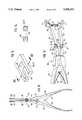
- FIG. 11is a lateral view of an implanting forceps for the compression implant according to FIGS. 8 through 10;
- FIG. 12is a perspective representation of the implanting forceps according to FIG. 11 attached to a compression implant;
- FIG. 13is a perspective representation of the end section of a finger-like gripper of the implanting forceps.
- FIG. 14is a sectional view taken along line XIV-XIV from FIG. 13.
- the compression implant 1which is shown in FIGS. 8, 9 and 10, includes of a threaded spindle 2 and two vertebra clamp jaws 3 and 4 of completely identical design, each of which is provided with threaded nuts 5 and 6 mounted pivotably in them.
- the threaded spindle 2 shown as a detail in FIG. 4has a first threaded section 7 with right-hand threads and a second threaded section 8 with left-hand threads.
- the end-face ends of the threaded sections 7 and 8are provided with an outwardly tapering, rounded cone 12 and 13 each, which have a cone angle ⁇ of about 60°.
- the two threaded sections 7 and 8each may be provided with metric threads with a diameter of, e.g., 4 mm.
- the two clamp jaws 3 and 4 of identical designare represented as details in FIGS. 1 through 3.
- Each of themhas an approximately semicircular claw 14, whose inner surface 15 is provided with triangular grooves or teeth 16 extending in the circumferential direction, and which has, as a whole, a trapezoidal or wedge-shaped cross-sectional shape with a wedge angle ⁇ of about 60°.
- the essentially semicylindrical inner surface 15 of the claw 14has two different radii of curvature R1, R2, with a common axis of curvature 20, wherein the larger radius of curvature R2 is approximately 6 mm and is located on the inner side adjacent to the transverse bore.
- body 17which is provided with a cylindrical transverse bore 18, whose axis 19 extends in parallel to the axis of curvature 20 of the inner surface 15 of the claw 14.
- the partially cylindrical wall 21 surrounding the transverse bore 18is provided with two diametric openings 22 and 23, wherein the upper opening 22 located on the rear side 24 is designed as a radial bore in relation to the bore axis 19, and the lower opening 23 is designed as an elongated hole.
- the axis 25 of the opening 22, which is designed as a radial bore, which axis intersects the axis 19,is also the axis of curvature for the semicircular end section 26 of the elongated hole 23, while the opposite end section 27, which is likewise semicircular, forms an opening angle 8 of about 60° with the axis 25.
- the threaded spindle 2 screwed oncan be pivoted by about 30°.
- the diameter D or the width W of the openings 22 and 23are each selected to be such that the threaded sections 7 and 8 of the threaded spindle can be passed through freely. In the exemplary embodiment, this width is ca. 4.1 mm.
- FIG. 7shows another clamp jaw 3', in which the claw 14' has two smaller inner radii R3 and R4, and in which the axis 25 of the opening 22, designed as a radial bore, forms a smaller angle ⁇ ' of about 23° with the rear side 24.
- clamp jaw 3'otherwise has the same design as the clamp jaw 3 or 4, so that it can be assembled into a compression implant 1 even with the threaded spindle 2 and the threaded nuts 5 and 6 to be described later, but the span of this compression implant is larger at equal threaded spindle length than in the case of the use of the clamp jaws 3 and 4.
- the threaded nuts 5 and 6are, in principle, of identical design, aside from the direction of their internal threads. As is apparent from FIGS. 5 and 6, they consist of a cylindrical rotary body 28 each with plane-parallel end faces 50, 51, which has, in its axial center, a diametrically extending threaded bore 29, into which either the threaded section 7 with the right-hand threads or the threaded section 8 with left-hand threads of the threaded spindle 2 can be screwed. Consequently, the threaded bore 29 of the threaded nut 5 is provided with right-hand threads, and the threaded nut 6 is provided with left-hand threads.
- the diameter of the rotary body 28is adapted to the internal diameter of the transverse bore 18 such that it can easily be introduced into the transverse bore 18 and can be mounted in it rotatably.
- the length of the rotary bodycorresponds to the width b of the clamp jaw 3, 4.
- the completely assembled compression implant 1is placed surgically on the patient's vertebrae which are to be connected to one another, and this expansion of the clamp jaws 3 and 4 can be performed after introduction into the surgical incision. However, it may also be performed prior to introduction, if desired.
- FIGS. 11 through 14which is in the form of an expanding forceps. It consists of two bent handles 32 and 33, which are hinged to one another by a hinge 31, are pressed against one another by two leaf springs 34 and 35, and are provided with finger-like grippers 36 and 37 each.
- the grippers 36 and 37are connected by joints 38 and 39 to fingers 40 and 41 of the handles 32 and 33, respectively, whose respective axes 42 and 43 each extend at right angles to the hinge axis 31'.
- the grippers 36 and 37can be pivoted, to a limited extent, in both directions by about 15° each from a central position aligned with the fingers 40 and 41, so that they are able to occupy approximately the position shown in FIG. 12 in one of the end positions.
- the end sections 46 and 47 of the grippers 36 and 37are each designed in a mirror-inverted manner, and each of them is provided with depressions 48, which have the cross-sectional shape of a cylinder section and into which a U-shaped slot 49 each, which is open at the front end, leads.
- This shaping of the end sections 46 and 47makes it possible to place these end sections, in the manner shown in FIG. 12, on the clamp jaws 3 and 4, which had already been screwed onto the threaded spindle 2 according to FIG. 8, from the inside, so that the clamp jaws 3 and 4 will be held nonrotatably in an interlocking manner, and will occupy mutually parallel positions.
- the manipulating device 30a surgeon will be able to easily implant the compression implant 1 according to the present invention without the assistance of a second person. Due to the two clamp jaws 3 and 4 being nonrotatably held in the end sections 46 and 47 of the grippers 36 and 37, it is also easy to rotate the threaded spindle 2 in the desired direction by applying a hexagon head wrench on the hexagon 9, so that compression, i.e., bringing together of the two clamp jaws 3 and 4, will be achieved.
Landscapes
- Health & Medical Sciences (AREA)
- Orthopedic Medicine & Surgery (AREA)
- Neurology (AREA)
- Life Sciences & Earth Sciences (AREA)
- Surgery (AREA)
- Heart & Thoracic Surgery (AREA)
- Engineering & Computer Science (AREA)
- Biomedical Technology (AREA)
- Nuclear Medicine, Radiotherapy & Molecular Imaging (AREA)
- Medical Informatics (AREA)
- Molecular Biology (AREA)
- Animal Behavior & Ethology (AREA)
- General Health & Medical Sciences (AREA)
- Public Health (AREA)
- Veterinary Medicine (AREA)
- Prostheses (AREA)
- Surgical Instruments (AREA)
- Materials For Medical Uses (AREA)
Abstract
Description
The present invention pertains to a medical technical compression implant for the surgical repair of damage to the spinal column, especially in the cervical region, consisting of two clamp jaws, which are bent in the shape of a hook, are directed against each other, are connected by a threaded spindle, and can be contracted by reducing the distance between them, and of a manipulating device for the compression implant.
Compression implants of this class are used in surgical medicine, especially in operations for restoring the normal functions of pathologic or injury-related damage to the spinal column.
Curvatures of the spine may be the consequence of, e.g., disturbances of growth, which lead to wedge-shaped changes in the spinal column, or they may be due to tuberculous collapse of individual vertebral bodies. Vitamin D deficiency has also been known to be able to lead to severe rachitic curvatures of the spine, and calcipenia has been known to be able to cause collapse of vertebrae after the menopause. In addition, accident-related vertebral fractures, which must be treated surgically, occur with increasing frequency.
To correct such postural defects or to stabilize these disease-related or traumatic vertebral fractures, individual vertebrae or vertebral prostheses are mutually braced, clamped, or fixed to or with one another in practice. Metal wires have hitherto been used for this purpose in order to stabilize the vertebrae affected or to attach the aforementioned vertebral prostheses to the vertebrae.
Screw clamps, whose jaws can be pushed over two or more vertebrae during the operation and which can be contracted with a conventional set screw, e.g., in the manner of pipe clamps or the like, have been known as well. These jaws have a hook-shaped design. While one jaw is provided with a smooth bore for passing through the screw shaft, the second jaw has a bore provided with internal threads, into which the screw can be screwed in order to move the two jaws toward one another, and the screw head is located on the outside at the edge of the smooth bore.
These prior-art clamps are unsatisfactory for several reasons. First of all, it is impossible for a single surgeon to insert such a clamp. In addition, its manipulation is very complicated and, in particular, it requires a large surgical incision opening to permit insertion of such a clamp, because the screw head, which is arranged at one end of the screw to which the rotating tool, e.g., a 90° offset screw driver, must be attached. In addition, the two jaws, must be held individually during rotation, as long as screwing in of the screw is taking place, in order to prevent them from leaving the position required for their proper function. Due to the relatively long span distance and the simple, self-locking thread, a very great number of rotations of the screw are also necessary in order to bring the two jaws to the intended final distance needed for proper function.
It is a primary object of the present invention to provide an improved compression implant of the type described in the introduction, which can be manipulated with greater ease and greater simplicity, and which, in particular, can be implanted without the assistance of a second surgeon, and which requires only a short surgical incision in the patient despite its large span.
This task is accomplished according to the present invention by the threaded spindle having--between two threaded sections, one with right-hand threads and another with left-hand threads--a wrench profile for the interlocking attachment of a rotating tool, and by both clamp jaws having, as threaded nuts, pivotably mounted cylindrical rotary bodies with diametrical threaded bores for screwing in the threaded sections.
Of particular advantage is the use of a threaded spindle provided with threaded sections cut in opposite directions, with obligatorily self-locking threads, because double the amount of change is achieved by one rotation of the spindle compared with the prior-art clamp. In addition, the pivoting mount of the threaded nuts in the two clamp jaws offers the highly advantageous possibility for the clamp jaws to pivot apart additionally when they are located at the ends of the threaded spindle, in order to obtain a larger opening width or span. Due to the fact that the wrench profile of the threaded spindle is located in the middle between the two threaded sections with opposite thread directions, it is also possible to attach the wrench needed for rotating the threaded spindle, e.g., a hexagon head wrench, in the middle of the thread. As a result, the length of the necessary surgical incision can be kept substantially shorter than in the case of the use of the prior-art clamps. The pivoting apart of the clamp jaws may also be performed after introduction into the surgical opening. Another advantage is the fact that two clamp jaws may have completely identical design; a particularly favorable design of the clamp jaws in terms of the pivotability and mounting of the rotary bodies designed as threaded nuts wherein the threaded nuts are mounted in cylindrical transverse bores of the clamp jaws, the clamp jaws having walls with diametrical openings for passing through the threaded section of the threaded spindle. The opening on the inner side of the clamp jaw has an elongated hole which permits the threaded spindle, which passes therethrough and is screwed into the threaded nut, to pivot by at least 15° around the axis of the transverse bore.
A very substantial additional advantage is achieved by the design of the opening located on the outer side of the clamped jaw as a radial bore, with respect to the axis of the transverse bore, and wherein the threaded spindle has an outwardly tapering cone which allows the pivoting of the clamp jaw around the axis of the transverse bore in cooperation with the inner edge or inner surface opening designed as a radial bore. The additional pivoting movement of the two clamp jaws around the axis of the transverse bores permits not only a shorter threaded spindle to be used, but also a greater pulling movement of the two clamp jaws during the initial phase of the screwing in of the threaded spindle into the two threaded nuts to be achieved. This also leads to substantially greater ease of manipulation and to time savings during insertion.
The clamp jaws are preferably of identical design and have a claw each, provided with an approximately semicylindrical inner surface, with a geometric axis of curvature extending at least approximately in parallel to the axis of the transverse bore. The inner surfaces of the claws have grooves or toothed profiles extending in the circumferential direction. The claws are preferably provided with a trapezoidal cross-sectional profile. The inner surface of the claw is provided with two different radii of curvature and the larger radius of curvature is located on the inner side located adjacent to the transverse bore. A semicircular in section of the opening designed as an elongated hole, the end adjacent to the claw, extends coaxially with the diametrically opposed opening designed as a radial bore. The axis of the opening designed as a radial bore forms a right angle with the rear side of the clamp jaw.
Using the manipulating with end section of grippers of an extending forceps, which grippers have a finger-like design, are provided with slots, which are open at their ends, and--in the area of the slots--with a depression on the outer side of the grippers for holding the clamp jaws in interlocking, non-rotatable manner, the compression implant according to the present invention can be inserted and held securely and in correct position in a highly advantageous and especially correctly functioning manner and secured against rotation during the rotary movements of the threaded spindle, and it is guaranteed that the two opposite clamp jaws cannot be displaced in relation to one another. The design of the manipulating device wherein the grippers with the slots and depressions are hinged to fingers of handles, which fingers are laterally pivotable to a limited extent due to a joint and are connected to one another by a hinge, makes it possible, in particular, to achieve a large range of pivoting of the wrench to be attached to the wrench profile, so that the necessary frequency of transposing the wrench can be greatly reduced.
The various features of novelty which characterize the invention are pointed out with particularity in the claims annexed to and forming a part of this disclosure. For a better understanding of the invention, its operating advantages and specific objects attained by its uses, reference is made to the accompanying drawings and descriptive matter in which preferred embodiments of the invention are illustrated.
In the drawings:
FIG. 1 is a top view of a clamp jaw according to the invention;
FIG. 2 is a sectional view taken along line II--II from FIG. 1;
FIG. 3 is a claw profile according to a sectional view taken along line III--III from FIG. 2;
FIG. 4 is a top view of a threaded spindle;
FIG. 5 is a lateral view of a threaded nut according to the invention;
FIG. 6 is a sectional view taken along line VI--VI from FIG. 5;
FIG. 7 is a sectional view of another embodiment of the clamp jaw;
FIG. 8 is a cutaway lateral view of the complete compression implant with the clamp jaws pivoted apart;
FIG. 9 is a view of the compression implant according to FIG. 8, in which the clamp jaws are located in an only partially pivoted position;
FIG. 10 is a view of the compression implant according to FIGS. 8 and 9, in which the two clamp jaws are in their normal position;
FIG. 11 is a lateral view of an implanting forceps for the compression implant according to FIGS. 8 through 10;
FIG. 12 is a perspective representation of the implanting forceps according to FIG. 11 attached to a compression implant;
FIG. 13 is a perspective representation of the end section of a finger-like gripper of the implanting forceps; and
FIG. 14 is a sectional view taken along line XIV-XIV from FIG. 13.
The compression implant 1, which is shown in FIGS. 8, 9 and 10, includes of a threadedspindle 2 and twovertebra clamp jaws 3 and 4 of completely identical design, each of which is provided with threaded nuts 5 and 6 mounted pivotably in them.
The threadedspindle 2 shown as a detail in FIG. 4 has a first threadedsection 7 with right-hand threads and a second threadedsection 8 with left-hand threads. Awrench profile 9, which is separated from the threads of the two threadedsections recesses sections sections rounded cone sections
The twoclamp jaws 3 and 4 of identical design are represented as details in FIGS. 1 through 3. Each of them has an approximatelysemicircular claw 14, whoseinner surface 15 is provided with triangular grooves orteeth 16 extending in the circumferential direction, and which has, as a whole, a trapezoidal or wedge-shaped cross-sectional shape with a wedge angle β of about 60°. The essentially semicylindricalinner surface 15 of theclaw 14 has two different radii of curvature R1, R2, with a common axis ofcurvature 20, wherein the larger radius of curvature R2 is approximately 6 mm and is located on the inner side adjacent to the transverse bore.
To theclaw 14 there is connected aroundbody 17, which is provided with a cylindrical transverse bore 18, whoseaxis 19 extends in parallel to the axis ofcurvature 20 of theinner surface 15 of theclaw 14. The partiallycylindrical wall 21 surrounding thetransverse bore 18 is provided with twodiametric openings upper opening 22 located on therear side 24 is designed as a radial bore in relation to thebore axis 19, and thelower opening 23 is designed as an elongated hole. Theaxis 25 of theopening 22, which is designed as a radial bore, which axis intersects theaxis 19, is also the axis of curvature for thesemicircular end section 26 of theelongated hole 23, while theopposite end section 27, which is likewise semicircular, forms anopening angle 8 of about 60° with theaxis 25. With such an opening width, the threadedspindle 2 screwed on can be pivoted by about 30°. The diameter D or the width W of theopenings sections
As is apparent from FIG. 2, theaxis 25 of theopening 22 in theclamp jaw 3, 4 shown forms a right angle γ with the flatrear side 24 of theclamp jaw 3, 4. In contrast, FIG. 7 shows another clamp jaw 3', in which the claw 14' has two smaller inner radii R3 and R4, and in which theaxis 25 of theopening 22, designed as a radial bore, forms a smaller angle γ' of about 23° with therear side 24. This the clamp jaw 3' otherwise has the same design as theclamp jaw 3 or 4, so that it can be assembled into a compression implant 1 even with the threadedspindle 2 and the threaded nuts 5 and 6 to be described later, but the span of this compression implant is larger at equal threaded spindle length than in the case of the use of theclamp jaws 3 and 4.
The threaded nuts 5 and 6 are, in principle, of identical design, aside from the direction of their internal threads. As is apparent from FIGS. 5 and 6, they consist of a cylindricalrotary body 28 each with plane-parallel end faces 50, 51, which has, in its axial center, a diametrically extending threaded bore 29, into which either the threadedsection 7 with the right-hand threads or the threadedsection 8 with left-hand threads of the threadedspindle 2 can be screwed. Consequently, the threaded bore 29 of the threaded nut 5 is provided with right-hand threads, and the threaded nut 6 is provided with left-hand threads. The diameter of therotary body 28 is adapted to the internal diameter of thetransverse bore 18 such that it can easily be introduced into thetransverse bore 18 and can be mounted in it rotatably. The length of the rotary body corresponds to the width b of theclamp jaw 3, 4.
In the assembled state, the threadedspindle 2 with its the right-hand threadedsection 7, which passes through thelower opening 23 designed as an elongated hole, is screwed into the internal threadedsection 28 of the threaded nut 5 to the extent that the rounding of thecone 12 is still located inside thetransverse bore 18. In a mirror-inverted manner relative to this, the threadedsection 8 with the left-hand thread is screwed analogously into the threaded nut 6 to the same extent, so that the twoclamp jaws 3 and 4 can still be pivoted in the outward direction around theaxes 19 of their the transverse bores 18 to the extent that the delimiting edges 27 of the end sections of their theopenings 23, designed as elongated holes, are in contact with the circumference of the threadedsections gripping clamps 3 and 4 is somewhat larger than the distance B between theaxes 19 of the transverse bores 18 in the same position.
In this state, the completely assembled compression implant 1 is placed surgically on the patient's vertebrae which are to be connected to one another, and this expansion of theclamp jaws 3 and 4 can be performed after introduction into the surgical incision. However, it may also be performed prior to introduction, if desired.
During the subsequent rotation of the threadedspindle 2 in the tensioning direction, the expanded position as shown in FIG. 8 will be increasingly reduced, and changed over into the normal position according to FIG. 10, in which the axis of the threadedspindle 2 and theaxis 25 of theupper opening 22 extend coaxially with one another, and the threadedspindle 2 also forms a right angle , each with therear side 24 of theclamp jaw 3 and 4.
This reduction of the expanded position is brought about by the twocones sections openings 32 designed as radial bores and causing, in cooperation with the inner lateral edges or oblique guiding surfaces of theopenings 22, theclamp jaws 3 and 4 to pivot in the tensioning direction, so that not only a contraction, i.e., reduction of the distance B between the twoclamp jaws 3 and 4, which is brought about by the threads, will take place, but a pivoting movement in the tensioning direction will also be brought about in the area in which the threadedspindle 2 is initially screwed into the two threaded nuts 5 and 6. Consequently, the tensioning effect is substantially stronger in this initial area of tensioning according to FIGS. 8 and 9 than thereafter, when theclamp jaws 3 and 4 assume their angular position shown in FIG. 10 in relation to the axis of the threadedspindle 2.
The implantation of such compression implants 1 can be substantially facilitated with the manipulatingdevice 30 represented in FIGS. 11 through 14, which is in the form of an expanding forceps. It consists of twobent handles hinge 31, are pressed against one another by twoleaf springs like grippers grippers joints fingers handles respective axes surfaces respective fingers respective grippers grippers fingers
Theend sections grippers depressions 48, which have the cross-sectional shape of a cylinder section and into which aU-shaped slot 49 each, which is open at the front end, leads. This shaping of theend sections clamp jaws 3 and 4, which had already been screwed onto the threadedspindle 2 according to FIG. 8, from the inside, so that theclamp jaws 3 and 4 will be held nonrotatably in an interlocking manner, and will occupy mutually parallel positions.
Using this the manipulatingdevice 30, a surgeon will be able to easily implant the compression implant 1 according to the present invention without the assistance of a second person. Due to the twoclamp jaws 3 and 4 being nonrotatably held in theend sections grippers spindle 2 in the desired direction by applying a hexagon head wrench on thehexagon 9, so that compression, i.e., bringing together of the twoclamp jaws 3 and 4, will be achieved.
It is also conceivable to screw the twoclamp jaws 3 and 4 onto the threadedspindle 2 such that their theclaws 14 will be directed to the outside, so that expansion rather than compression of vertebrae can be brought about.
While specific embodiments of the invention have been shown and described in detail to illustrate the application of the principles of the invention, it will be understood that the invention may be embodied otherwise without departing from such principles.
Claims (9)
1. Medical technical compression implant for surgical repair of damage to the spine, comprising:
first and second vertebral clamp jaws, each with a hook-shaped portion sized to be applied over a vertebra and each with a cylindrical transverse bore;
first and second threaded nuts, each of said threaded nuts being pivotably mounted in said cylindrical transverse bore of one of said first and second jaws to each form a cylindrical rotary body, said threaded nuts each having a diametrical threaded bore, extending radially with respect to said cylindrical transverse bore;
a threaded spindle connecting said clamp jaws with hook-shaped portions facing each other, said threaded spindle having a wrench profile for attaching a rotating tool in an interlocking manner between a first threaded section and a second threaded section, said first threaded section having right hand threads and said second threaded section having left hand threads, said clamp jaws having walls surrounding said transverse bores with diametrical openings for passing through said threaded sections of said threaded spindle, said diametrical openings including an inner side opening formed as an elongated hole defining a pivot region for said threaded spindle.
2. Compression implant according to claim 1, wherein: said threaded spindle passes through said elongated hole, and is screwed into said threaded nut, said elongated hole pivot region allowing said thread spindle, screwed into said nut, to pivot by at least 15° around a central axis of said transverse bore.
3. Compression implant according to claim 2, wherein:
said diametrical openings include an outer side opening formed as a radial bore to said central axis of said transverse bore, said threaded spindle having at least one end, an outwardly tapering cone allowing pivoting of said clamp jaw, around said central axis of said transverse bore in a pulling direction, in cooperation with an inner edge of said outer opening formed as a radial bore.
4. Compression implant according to claim 2, wherein:
said two clamp jaws are formed of a substantially identical design with a claw provided with an approximately semicylindrical inner surface with a geometric axis of curvature extending at least approximately in parallel to said axis of said transverse bore.
5. Compression implant according to claim 4, wherein:
inner surfaces of said claws have grooves or tooth profiles extending in a circumferential direction.
6. Compression implant according to claim 4, wherein:
said claw has a trapezoidal cross-sectional profile.
7. Compression implant according to claim 4, wherein:
an inner surface of said claw has two different radii of curvature including a larger radius of curvature located on an inner side adjacent to said transverse bore.
8. Compression implant according to claim 3, wherein:
a semicircular end section of said inner opening, said end section being adjacent to said claw, extends coaxially with said outer opening designed as a radial bore.
9. Compression implant according to claim 2, wherein:
an axis of said inner opening forms a right angle with a rear side surface of said clamp jaw.
Applications Claiming Priority (2)
| Application Number | Priority Date | Filing Date | Title |
|---|---|---|---|
| CH03055/91ACH686610A5 (en) | 1991-10-18 | 1991-10-18 | Compression implant. |
| CH3055/91 | 1991-10-18 |
Publications (1)
| Publication Number | Publication Date |
|---|---|
| US5395370Atrue US5395370A (en) | 1995-03-07 |
Family
ID=4247605
Family Applications (1)
| Application Number | Title | Priority Date | Filing Date |
|---|---|---|---|
| US07/962,265Expired - LifetimeUS5395370A (en) | 1991-10-18 | 1992-10-16 | Vertebral compression clamp for surgical repair to damage to the spine |
Country Status (6)
| Country | Link |
|---|---|
| US (1) | US5395370A (en) |
| EP (1) | EP0537598B1 (en) |
| AT (1) | ATE133325T1 (en) |
| CA (1) | CA2080869C (en) |
| CH (1) | CH686610A5 (en) |
| DE (1) | DE59205155D1 (en) |
Cited By (144)
| Publication number | Priority date | Publication date | Assignee | Title |
|---|---|---|---|---|
| US5725582A (en)* | 1992-08-19 | 1998-03-10 | Surgicraft Limited | Surgical implants |
| FR2757761A1 (en)* | 1996-12-27 | 1998-07-03 | Stryker France Sa | SPINE OTEOSYNTHESIS SYSTEM WITH POSITION ADJUSTMENT |
| US5928232A (en)* | 1994-11-16 | 1999-07-27 | Advanced Spine Fixation Systems, Incorporated | Spinal fixation system |
| US5971669A (en)* | 1998-05-15 | 1999-10-26 | L.B. Foster Company | Mechnically stabilized retaining wall system having adjustable connection means for connecting precast concrete facing panels thereto |
| US5993486A (en)* | 1997-09-18 | 1999-11-30 | Senko Medical Instrument Mfg. Co., Ltd. | Artificial ligament |
| US6102912A (en)* | 1997-05-29 | 2000-08-15 | Sofamor S.N.C. | Vertebral rod of constant section for spinal osteosynthesis instrumentations |
| US6117136A (en)* | 1997-07-26 | 2000-09-12 | Ulrich Gmbh & Co. Kg | Hooks for implants to correct and stabilize the vertebral column |
| US6139548A (en)* | 1995-10-30 | 2000-10-31 | Spinal Concepts, Inc. | Sliding shaft variable length cross-link device for use with dual rod apparatus |
| FR2794357A1 (en)* | 1999-06-01 | 2000-12-08 | Frederic Fortin | DISTRACTION DEVICE FOR BONES OF CHILDREN HAVING HANGING AND ADJUSTMENT MEANS FOR TRACKING GROWTH |
| US6234705B1 (en) | 1999-04-06 | 2001-05-22 | Synthes (Usa) | Transconnector for coupling spinal rods |
| US6283967B1 (en) | 1999-12-17 | 2001-09-04 | Synthes (U.S.A.) | Transconnector for coupling spinal rods |
| US6352537B1 (en)* | 1998-09-17 | 2002-03-05 | Electro-Biology, Inc. | Method and apparatus for spinal fixation |
| EP1192911A2 (en) | 2000-09-22 | 2002-04-03 | Showa IKA Kohgyo Co., Ltd. | Bone connecting tool and connecting member thereof |
| US6432108B1 (en)* | 2000-01-24 | 2002-08-13 | Depuy Orthopaedics, Inc. | Transverse connector |
| US20030109929A1 (en)* | 2001-12-10 | 2003-06-12 | Waldemar Link Gmbh & Co. | Insertion instrument for sliding prostheses |
| US20030114853A1 (en)* | 2001-10-12 | 2003-06-19 | Ian Burgess | Polyaxial cross connector |
| US6620164B2 (en) | 2000-09-22 | 2003-09-16 | Showa Ika Kohgyo Co., Ltd. | Rod for cervical vertebra and connecting system thereof |
| US6641584B2 (en) | 2000-09-22 | 2003-11-04 | Showa Ika Kohgyo Co., Ltd. | Hook cable for fixing atlantoaxial joint and system for fixing the same |
| US6656180B2 (en) | 2001-09-05 | 2003-12-02 | Stahurski Consulting Inc. | Apparatus for retaining vertebrae in a desired spatial relationship |
| US20040049188A1 (en)* | 2002-09-09 | 2004-03-11 | Depuy Acromed, Inc. | Snap-on spinal rod connector |
| US6712825B2 (en) | 1998-10-02 | 2004-03-30 | Max Aebi | Spinal disc space distractor |
| US20040087948A1 (en)* | 2002-08-29 | 2004-05-06 | Loubert Suddaby | Spinal facet fixation device |
| US20040153071A1 (en)* | 1998-10-27 | 2004-08-05 | St. Francis Medical Technologies, Inc. | Interspinous process distraction system and method with positionable wing and method |
| US20040220568A1 (en)* | 1997-01-02 | 2004-11-04 | St. Francis Medical Technologies, Inc. | Method for lateral implantation of spinous process spacer |
| US20050010293A1 (en)* | 2003-05-22 | 2005-01-13 | Zucherman James F. | Distractible interspinous process implant and method of implantation |
| US20050165396A1 (en)* | 2001-07-18 | 2005-07-28 | Frederic Fortin | Flexible vertebral linking device |
| US20050228377A1 (en)* | 2004-04-07 | 2005-10-13 | Depuy Spine, Inc. | Spinal cross-connectors |
| US20050228326A1 (en)* | 2004-03-31 | 2005-10-13 | Depuy Spine, Inc. | Head-to-head connector spinal fixation system |
| US20050261768A1 (en)* | 2004-05-21 | 2005-11-24 | Trieu Hai H | Interspinous spacer |
| US20060058789A1 (en)* | 2004-08-27 | 2006-03-16 | Depuy Spine, Inc. | Dual rod cross connectors and inserter tools |
| US20060064091A1 (en)* | 2004-03-31 | 2006-03-23 | Depuy Spine, Inc. | Rod attachment for head to head cross connector |
| US20060136060A1 (en)* | 2002-09-10 | 2006-06-22 | Jean Taylor | Posterior vertebral support assembly |
| US20060184248A1 (en)* | 2005-02-17 | 2006-08-17 | Edidin Avram A | Percutaneous spinal implants and methods |
| US20060184247A1 (en)* | 2005-02-17 | 2006-08-17 | Edidin Avram A | Percutaneous spinal implants and methods |
| US20060241614A1 (en)* | 2005-04-12 | 2006-10-26 | Sdgi Holdings, Inc. | Implants and methods for posterior dynamic stabilization of a spinal motion segment |
| US20060264939A1 (en)* | 2003-05-22 | 2006-11-23 | St. Francis Medical Technologies, Inc. | Interspinous process implant with slide-in distraction piece and method of implantation |
| US20060264938A1 (en)* | 2005-03-21 | 2006-11-23 | St. Francis Medical Technologies, Inc. | Interspinous process implant having deployable wing and method of implantation |
| US20060265067A1 (en)* | 2003-05-22 | 2006-11-23 | St. Francis Medical Technologies, Inc. | Interspinous process implant with slide-in distraction piece and method of implantation |
| US20060271045A1 (en)* | 2005-05-27 | 2006-11-30 | Depuy Spine, Inc. | Spinal cross-connector |
| US20060271049A1 (en)* | 2005-04-18 | 2006-11-30 | St. Francis Medical Technologies, Inc. | Interspinous process implant having deployable wings and method of implantation |
| US20060271194A1 (en)* | 2005-03-22 | 2006-11-30 | St. Francis Medical Technologies, Inc. | Interspinous process implant having deployable wing as an adjunct to spinal fusion and method of implantation |
| US20070049932A1 (en)* | 2005-08-23 | 2007-03-01 | Aesculap Ag & Co. Kg | Rod to rod connector |
| US20070049934A1 (en)* | 2005-02-17 | 2007-03-01 | Edidin Avram A | Percutaneous spinal implants and methods |
| US20070055237A1 (en)* | 2005-02-17 | 2007-03-08 | Edidin Avram A | Percutaneous spinal implants and methods |
| US20070072459A1 (en)* | 2005-09-23 | 2007-03-29 | Stahurski Consulting Inc. | Apparatus for retaining vertebrae |
| US20070073292A1 (en)* | 2005-02-17 | 2007-03-29 | Kohm Andrew C | Percutaneous spinal implants and methods |
| US20070100340A1 (en)* | 2005-10-27 | 2007-05-03 | Sdgi Holdings, Inc. | Intervertebral prosthetic device for spinal stabilization and method of implanting same |
| US20070123870A1 (en)* | 2005-07-18 | 2007-05-31 | Jeon Dong M | Bi-polar screw assembly |
| US20070149909A1 (en)* | 2002-08-13 | 2007-06-28 | Frederic Fortin | Distraction and damping system which can be adjusted as the vertebral column grows |
| US20070167945A1 (en)* | 2006-01-18 | 2007-07-19 | Sdgi Holdings, Inc. | Intervertebral prosthetic device for spinal stabilization and method of manufacturing same |
| US20070191837A1 (en)* | 2006-01-27 | 2007-08-16 | Sdgi Holdings, Inc. | Interspinous devices and methods of use |
| US20070191838A1 (en)* | 2006-01-27 | 2007-08-16 | Sdgi Holdings, Inc. | Interspinous devices and methods of use |
| US20070225706A1 (en)* | 2005-02-17 | 2007-09-27 | Clark Janna G | Percutaneous spinal implants and methods |
| US20070225807A1 (en)* | 2005-02-17 | 2007-09-27 | Phan Christopher U | Percutaneous spinal implants and methods |
| US20070233074A1 (en)* | 2006-03-16 | 2007-10-04 | Sdgi Holdings, Inc. | Expandable device for insertion between anatomical structures and a procedure utilizing same |
| US20070265623A1 (en)* | 2005-02-17 | 2007-11-15 | Malandain Hugues F | Percutaneous Spinal Implants and Methods |
| US20070270824A1 (en)* | 2006-04-28 | 2007-11-22 | Warsaw Orthopedic, Inc. | Interspinous process brace |
| US20070270834A1 (en)* | 2006-05-04 | 2007-11-22 | Sdgi Holdings, Inc. | Expandable device for insertion between anatomical structures and a procedure utilizing same |
| US20070276368A1 (en)* | 2006-05-23 | 2007-11-29 | Sdgi Holdings, Inc. | Systems and methods for adjusting properties of a spinal implant |
| US20070276493A1 (en)* | 2005-02-17 | 2007-11-29 | Malandain Hugues F | Percutaneous spinal implants and methods |
| US20070276372A1 (en)* | 2005-02-17 | 2007-11-29 | Malandain Hugues F | Percutaneous Spinal Implants and Methods |
| US20070276496A1 (en)* | 2006-05-23 | 2007-11-29 | Sdgi Holdings, Inc. | Surgical spacer with shape control |
| US20070282442A1 (en)* | 2005-02-17 | 2007-12-06 | Malandain Hugues F | Percutaneous spinal implants and methods |
| US20080021468A1 (en)* | 2002-10-29 | 2008-01-24 | Zucherman James F | Interspinous process implants and methods of use |
| US20080021460A1 (en)* | 2006-07-20 | 2008-01-24 | Warsaw Orthopedic Inc. | Apparatus for insertion between anatomical structures and a procedure utilizing same |
| US20080033445A1 (en)* | 1997-01-02 | 2008-02-07 | Zucherman James F | Spine distraction implant and method |
| US20080039944A1 (en)* | 2005-02-17 | 2008-02-14 | Malandain Hugues F | Percutaneous Spinal Implants and Methods |
| US20080051905A1 (en)* | 1997-01-02 | 2008-02-28 | Zucherman James F | Supplemental spine fixation device and method |
| US20080058935A1 (en)* | 2005-02-17 | 2008-03-06 | Malandain Hugues F | Percutaneous spinal implants and methods |
| US20080114455A1 (en)* | 2006-11-15 | 2008-05-15 | Warsaw Orthopedic, Inc. | Rotating Interspinous Process Devices and Methods of Use |
| US20080114456A1 (en)* | 2006-11-15 | 2008-05-15 | Warsaw Orthopedic, Inc. | Spinal implant system |
| US20080132952A1 (en)* | 2005-02-17 | 2008-06-05 | Malandain Hugues F | Percutaneous spinal implants and methods |
| US20080140124A1 (en)* | 2006-12-07 | 2008-06-12 | Dong Myung Jeon | Spinal rod transverse connector system |
| US20080177315A1 (en)* | 2006-12-20 | 2008-07-24 | Aesculap Ii, Inc. | Rod to Rod Connector |
| US20080183223A1 (en)* | 2005-09-26 | 2008-07-31 | Jeon Dong M | Hybrid jointed bone screw system |
| US20080288078A1 (en)* | 2005-02-17 | 2008-11-20 | Kohm Andrew C | Percutaneous spinal implants and methods |
| US20090030523A1 (en)* | 2001-08-08 | 2009-01-29 | Jean Taylor | Veretebra Stabilizing Assembly |
| US20090043339A1 (en)* | 2007-05-22 | 2009-02-12 | K2M, Inc. | Universal transverse connector device |
| US20090093820A1 (en)* | 2007-10-09 | 2009-04-09 | Warsaw Orthopedic, Inc. | Adjustable spinal stabilization systems |
| US20090118766A1 (en)* | 2007-11-02 | 2009-05-07 | Jongsoo Park | Intervertebral Stabilization Devices |
| US20090143823A1 (en)* | 2008-11-13 | 2009-06-04 | Jeon Dong M | Transverse connector system for spinal rods |
| US20090171395A1 (en)* | 2007-12-28 | 2009-07-02 | Jeon Dong M | Dynamic spinal rod system |
| US20090192548A1 (en)* | 2008-01-25 | 2009-07-30 | Jeon Dong M | Pedicle-laminar dynamic spinal stabilization device |
| US20090198245A1 (en)* | 2008-02-04 | 2009-08-06 | Phan Christopher U | Tools and methods for insertion and removal of medical implants |
| US20090198337A1 (en)* | 2008-02-04 | 2009-08-06 | Phan Christopher U | Medical implants and methods |
| US20090198277A1 (en)* | 2007-12-28 | 2009-08-06 | Osteomed Spine, Inc. | Bone tissue fixation device and method |
| US20090194206A1 (en)* | 2008-01-31 | 2009-08-06 | Jeon Dong M | Systems and methods for wrought nickel/titanium alloy flexible spinal rods |
| US20090227990A1 (en)* | 2006-09-07 | 2009-09-10 | Stoklund Ole | Intercostal spacer device and method for use in correcting a spinal deformity |
| US20090240283A1 (en)* | 2008-03-18 | 2009-09-24 | Warsaw Orthopedic, Inc. | Implants and methods for inter-spinous process dynamic stabilization of a spinal motion segment |
| US20090240280A1 (en)* | 2008-03-19 | 2009-09-24 | Jeffrey Chun Wang | Interspinous implant, tools and methods of implanting |
| US20090248090A1 (en)* | 2007-12-28 | 2009-10-01 | Pronto Products, Llc | Rib bone tissue clamp |
| US20090248079A1 (en)* | 2008-03-26 | 2009-10-01 | Kwak Seungkyu Daniel | S-Shaped Interspinous Process Spacer Having Tight Access Offset Hooks |
| US20090248076A1 (en)* | 2008-03-26 | 2009-10-01 | Reynolds Martin A | Interspinous Process Spacer Having Tight Access Offset Hooks |
| US20090270921A1 (en)* | 2008-02-14 | 2009-10-29 | Krause William R | Flexible spine components having a concentric slot |
| US20090275982A1 (en)* | 2006-04-13 | 2009-11-05 | Jean Taylor | Device for treating vertebrae, including an interspinous implant |
| US20090318967A1 (en)* | 2007-01-23 | 2009-12-24 | Dong Myung Jeon | Spacer for use in a surgical operation for spinous process of spine |
| US20100004744A1 (en)* | 1997-01-02 | 2010-01-07 | Kyphon Sarl | Interspinous process distraction system and method with positionable wing and method |
| US20100004697A1 (en)* | 2005-10-06 | 2010-01-07 | Frederic Fortin | Disengageable Anti-Return Device for a Rib Distractor |
| US20100030549A1 (en)* | 2008-07-31 | 2010-02-04 | Lee Michael M | Mobile device having human language translation capability with positional feedback |
| US20100042150A1 (en)* | 2005-03-31 | 2010-02-18 | Warsaw Orthopedic, Inc. | Intervertebral prosthetic device for spinal stabilization and method of manufacturing same |
| US20100049256A1 (en)* | 2007-01-30 | 2010-02-25 | Dong Myung Jeon | Anterior cerivcal plating system |
| US20100070038A1 (en)* | 2006-11-08 | 2010-03-18 | Jean Taylor | Interspinous implant |
| US7691130B2 (en) | 2006-01-27 | 2010-04-06 | Warsaw Orthopedic, Inc. | Spinal implants including a sensor and methods of use |
| US20100106252A1 (en)* | 2008-10-29 | 2010-04-29 | Kohm Andrew C | Spinal implants having multiple movable members |
| US20100114166A1 (en)* | 2008-11-05 | 2010-05-06 | Andrew Kohm | Extension limiting devices and methods of use for the spine |
| US20100211101A1 (en)* | 2005-04-29 | 2010-08-19 | Warsaw Orthopedic, Inc. | Spinous Process Stabilization Devices and Methods |
| US7803190B2 (en) | 2002-10-29 | 2010-09-28 | Kyphon SÀRL | Interspinous process apparatus and method with a selectably expandable spacer |
| US7846186B2 (en) | 2005-06-28 | 2010-12-07 | Kyphon SÀRL | Equipment for surgical treatment of two vertebrae |
| US20100312277A1 (en)* | 2009-06-05 | 2010-12-09 | Kyphon Sarl | Multi-level interspinous implants and methods of use |
| US20100318127A1 (en)* | 2009-06-12 | 2010-12-16 | Kyphon Sarl | Interspinous implant and methods of use |
| US7896902B2 (en) | 2006-04-05 | 2011-03-01 | Dong Myung Jeon | Multi-axial double locking bone screw assembly |
| US20110077686A1 (en)* | 2009-09-29 | 2011-03-31 | Kyphon Sarl | Interspinous process implant having a compliant spacer |
| US7918876B2 (en) | 2003-03-24 | 2011-04-05 | Theken Spine, Llc | Spinal implant adjustment device |
| US20110098745A1 (en)* | 2009-10-28 | 2011-04-28 | Kyphon Sarl | Interspinous process implant and method of implantation |
| US7955392B2 (en) | 2006-12-14 | 2011-06-07 | Warsaw Orthopedic, Inc. | Interspinous process devices and methods |
| US20110172709A1 (en)* | 2010-01-13 | 2011-07-14 | Kyphon Sarl | Dynamic interspinous process device |
| US20110172596A1 (en)* | 2010-01-13 | 2011-07-14 | Kyphon Sarl | Interspinous process spacer diagnostic balloon catheter and methods of use |
| US7998174B2 (en) | 2005-02-17 | 2011-08-16 | Kyphon Sarl | Percutaneous spinal implants and methods |
| US20110213301A1 (en)* | 2010-02-26 | 2011-09-01 | Kyphon SÀRL | Interspinous process spacer diagnostic parallel balloon catheter and methods of use |
| US8029550B2 (en) | 2006-01-18 | 2011-10-04 | Warsaw Orthopedic, Inc. | Intervertebral prosthetic device for spinal stabilization and method of implanting same |
| US8048117B2 (en) | 2003-05-22 | 2011-11-01 | Kyphon Sarl | Interspinous process implant and method of implantation |
| US8048118B2 (en) | 2006-04-28 | 2011-11-01 | Warsaw Orthopedic, Inc. | Adjustable interspinous process brace |
| US8100943B2 (en) | 2005-02-17 | 2012-01-24 | Kyphon Sarl | Percutaneous spinal implants and methods |
| US8118844B2 (en) | 2006-04-24 | 2012-02-21 | Warsaw Orthopedic, Inc. | Expandable device for insertion between anatomical structures and a procedure utilizing same |
| US8147548B2 (en) | 2005-03-21 | 2012-04-03 | Kyphon Sarl | Interspinous process implant having a thread-shaped wing and method of implantation |
| US8349013B2 (en) | 1997-01-02 | 2013-01-08 | Kyphon Sarl | Spine distraction implant |
| US8361117B2 (en) | 2006-11-08 | 2013-01-29 | Depuy Spine, Inc. | Spinal cross connectors |
| US8591548B2 (en) | 2011-03-31 | 2013-11-26 | Warsaw Orthopedic, Inc. | Spinous process fusion plate assembly |
| US8591549B2 (en) | 2011-04-08 | 2013-11-26 | Warsaw Orthopedic, Inc. | Variable durometer lumbar-sacral implant |
| US8641762B2 (en) | 2006-10-24 | 2014-02-04 | Warsaw Orthopedic, Inc. | Systems and methods for in situ assembly of an interspinous process distraction implant |
| US8771319B2 (en) | 2012-04-16 | 2014-07-08 | Aesculap Implant Systems, Llc | Rod to rod cross connector |
| US8814908B2 (en) | 2010-07-26 | 2014-08-26 | Warsaw Orthopedic, Inc. | Injectable flexible interspinous process device system |
| US8828056B2 (en) | 2012-04-16 | 2014-09-09 | Aesculap Implant Systems, Llc | Rod to rod cross connector |
| US8911476B2 (en) | 2009-06-23 | 2014-12-16 | Osteomed, Llc | Bone plates, screws, and instruments |
| US8961564B2 (en) | 2008-12-23 | 2015-02-24 | Osteomed Llc | Bone tissue clamp |
| WO2015161071A1 (en)* | 2014-04-16 | 2015-10-22 | Buttermann Glenn R | Adjustable screw-clamp orthopedic apparatus |
| US20150327847A1 (en)* | 2013-12-30 | 2015-11-19 | Fehling Medical Corporation | Sternum Spreader |
| US9211147B2 (en) | 2009-06-23 | 2015-12-15 | Osteomed Llc | Spinous process fusion implants |
| US9956007B2 (en) | 2011-11-17 | 2018-05-01 | Howmedica Osteonics Corp. | Interspinous spacers and associated methods of use and manufacture |
| US10034693B2 (en) | 2016-07-07 | 2018-07-31 | Mark S. Stern | Spinous laminar clamp assembly |
| US10098665B2 (en) | 2012-08-01 | 2018-10-16 | DePuy Synthes Products, Inc. | Spine derotation system |
| US20190038323A1 (en)* | 2015-08-31 | 2019-02-07 | Bpath | Vertebral implant, method for the placement of such an implant and tool for the placement of the implant |
| CN114404010A (en)* | 2021-12-23 | 2022-04-29 | 山东师范大学 | Adjustable vertebral lamina hook internal fixation device for lumbar isthmus fissure |
| US20240341814A1 (en)* | 2023-04-13 | 2024-10-17 | University Of Cincinnati | Adjustable device for correcting scoliosis |
Families Citing this family (3)
| Publication number | Priority date | Publication date | Assignee | Title |
|---|---|---|---|---|
| FR2709411B1 (en)* | 1993-09-03 | 1995-11-17 | Sofamor | Stabilizing forceps of a cervical spinal segment. |
| FR2929830A1 (en)* | 2008-04-15 | 2009-10-16 | Warsaw Orthopedic Inc | SURGICAL TOOL FOR HANDLING AN IMPLANT, ESPECIALLY AN ANCHOR ELEMENT IMPLANTED IN A VERTEBRA |
| US8002748B2 (en)* | 2009-04-24 | 2011-08-23 | Kyphon Sarl | Digital syringe with compensation control |
Citations (6)
| Publication number | Priority date | Publication date | Assignee | Title |
|---|---|---|---|---|
| US2226651A (en)* | 1938-12-16 | 1940-12-31 | Raymond D York | Crucible support |
| US4289123A (en)* | 1980-03-31 | 1981-09-15 | Dunn Harold K | Orthopedic appliance |
| SU1074514A1 (en)* | 1982-06-18 | 1984-02-23 | Саратовский научно-исследовательский институт травматологии и ортопедии | Apparatus for correction and fixation of spinal column |
| US4611582A (en)* | 1983-12-27 | 1986-09-16 | Wisconsin Alumni Research Foundation | Vertebral clamp |
| DE3802833A1 (en)* | 1987-02-27 | 1988-09-08 | Gerhard Weber | Internal fixator |
| SU1517954A2 (en)* | 1987-09-23 | 1989-10-30 | Саратовский научно-исследовательский институт травматологии и ортопедии | Arrangement for correcting and fixing spinal column |
Family Cites Families (7)
| Publication number | Priority date | Publication date | Assignee | Title |
|---|---|---|---|---|
| DE561561C (en)* | 1929-02-12 | 1932-10-15 | Heinrich C Ulrich | Device for the treatment of broken bones |
| US4274401A (en)* | 1978-12-08 | 1981-06-23 | Miskew Don B W | Apparatus for correcting spinal deformities and method for using |
| CH646857A5 (en)* | 1980-11-18 | 1984-12-28 | Sulzer Ag | SPONDYLODESIS STABILIZER. |
| DE3434753C2 (en)* | 1984-03-14 | 1986-12-04 | Fraunhofer-Gesellschaft zur Förderung der angewandten Forschung e.V., 8000 München | Implant for the surgical correction of the lateral curvature of the spine |
| US4771767A (en)* | 1986-02-03 | 1988-09-20 | Acromed Corporation | Apparatus and method for maintaining vertebrae in a desired relationship |
| US5084049A (en)* | 1989-02-08 | 1992-01-28 | Acromed Corporation | Transverse connector for spinal column corrective devices |
| DE9004240U1 (en)* | 1990-04-11 | 1991-08-08 | Waldemar Link Gmbh & Co, 2000 Hamburg | Bone surgical holder |
- 1991
- 1991-10-18CHCH03055/91Apatent/CH686610A5/ennot_activeIP Right Cessation
- 1992
- 1992-10-06ATAT92117050Tpatent/ATE133325T1/ennot_activeIP Right Cessation
- 1992-10-06EPEP92117050Apatent/EP0537598B1/ennot_activeExpired - Lifetime
- 1992-10-06DEDE59205155Tpatent/DE59205155D1/ennot_activeExpired - Fee Related
- 1992-10-16USUS07/962,265patent/US5395370A/ennot_activeExpired - Lifetime
- 1992-10-19CACA002080869Apatent/CA2080869C/ennot_activeExpired - Fee Related
Patent Citations (6)
| Publication number | Priority date | Publication date | Assignee | Title |
|---|---|---|---|---|
| US2226651A (en)* | 1938-12-16 | 1940-12-31 | Raymond D York | Crucible support |
| US4289123A (en)* | 1980-03-31 | 1981-09-15 | Dunn Harold K | Orthopedic appliance |
| SU1074514A1 (en)* | 1982-06-18 | 1984-02-23 | Саратовский научно-исследовательский институт травматологии и ортопедии | Apparatus for correction and fixation of spinal column |
| US4611582A (en)* | 1983-12-27 | 1986-09-16 | Wisconsin Alumni Research Foundation | Vertebral clamp |
| DE3802833A1 (en)* | 1987-02-27 | 1988-09-08 | Gerhard Weber | Internal fixator |
| SU1517954A2 (en)* | 1987-09-23 | 1989-10-30 | Саратовский научно-исследовательский институт травматологии и ортопедии | Arrangement for correcting and fixing spinal column |
Cited By (297)
| Publication number | Priority date | Publication date | Assignee | Title |
|---|---|---|---|---|
| US5725582A (en)* | 1992-08-19 | 1998-03-10 | Surgicraft Limited | Surgical implants |
| US5928232A (en)* | 1994-11-16 | 1999-07-27 | Advanced Spine Fixation Systems, Incorporated | Spinal fixation system |
| US6139548A (en)* | 1995-10-30 | 2000-10-31 | Spinal Concepts, Inc. | Sliding shaft variable length cross-link device for use with dual rod apparatus |
| FR2757761A1 (en)* | 1996-12-27 | 1998-07-03 | Stryker France Sa | SPINE OTEOSYNTHESIS SYSTEM WITH POSITION ADJUSTMENT |
| WO1998029046A1 (en)* | 1996-12-27 | 1998-07-09 | Stryker France S.A. | Adjustable osteosynthetic system of the rachis |
| AU727020B2 (en)* | 1996-12-27 | 2000-11-30 | Stryker France | Position-adjustable spinal osteosynthesis system |
| US6090113A (en)* | 1996-12-27 | 2000-07-18 | Stryker France S.A. | Adjustable osteosynthesis system of the rachis |
| US20080051905A1 (en)* | 1997-01-02 | 2008-02-28 | Zucherman James F | Supplemental spine fixation device and method |
| US20100004744A1 (en)* | 1997-01-02 | 2010-01-07 | Kyphon Sarl | Interspinous process distraction system and method with positionable wing and method |
| US8540751B2 (en) | 1997-01-02 | 2013-09-24 | Warsaw Orthopedic, Inc. | Spine distraction implant and method |
| US7901432B2 (en) | 1997-01-02 | 2011-03-08 | Kyphon Sarl | Method for lateral implantation of spinous process spacer |
| US20080058941A1 (en)* | 1997-01-02 | 2008-03-06 | Zucherman James F | Supplemental spine fixation device and method |
| US7918877B2 (en)* | 1997-01-02 | 2011-04-05 | Kyphon Sarl | Lateral insertion method for spinous process spacer with deployable member |
| US7955356B2 (en) | 1997-01-02 | 2011-06-07 | Kyphon Sarl | Laterally insertable interspinous process implant |
| US20060235521A1 (en)* | 1997-01-02 | 2006-10-19 | St. Francis Medical Technologies, Inc. | Spinous process implant with tethers |
| US20080065086A1 (en)* | 1997-01-02 | 2008-03-13 | Zucherman James F | Spine distraction implant and method |
| US7666209B2 (en) | 1997-01-02 | 2010-02-23 | Kyphon Sarl | Spine distraction implant and method |
| US7993374B2 (en) | 1997-01-02 | 2011-08-09 | Kyphon Sarl | Supplemental spine fixation device and method |
| US20080183210A1 (en)* | 1997-01-02 | 2008-07-31 | Zucherman James F | Supplemental spine fixation device and method |
| US8740943B2 (en) | 1997-01-02 | 2014-06-03 | Warsaw Orthopedic, Inc. | Spine distraction implant and method |
| US8821548B2 (en) | 1997-01-02 | 2014-09-02 | Warsaw Orthopedic, Inc. | Spine distraction implant and method |
| US8672975B2 (en) | 1997-01-02 | 2014-03-18 | Warsaw Orthopedic, Inc | Spine distraction implant and method |
| US20080021560A1 (en)* | 1997-01-02 | 2008-01-24 | Zucherman James F | Spine distraction implant and method |
| US20080033445A1 (en)* | 1997-01-02 | 2008-02-07 | Zucherman James F | Spine distraction implant and method |
| US8568455B2 (en) | 1997-01-02 | 2013-10-29 | Warsaw Orthopedic, Inc. | Spine distraction implant and method |
| US20080039859A1 (en)* | 1997-01-02 | 2008-02-14 | Zucherman James F | Spine distraction implant and method |
| US8029542B2 (en) | 1997-01-02 | 2011-10-04 | Kyphon Sarl | Supplemental spine fixation device and method |
| US20070203495A1 (en)* | 1997-01-02 | 2007-08-30 | Zucherman James F | Spine distraction implant and method |
| US7828822B2 (en) | 1997-01-02 | 2010-11-09 | Kyphon SÀRL | Spinous process implant |
| US8617211B2 (en) | 1997-01-02 | 2013-12-31 | Warsaw Orthopedic, Inc. | Spine distraction implant and method |
| US20080015700A1 (en)* | 1997-01-02 | 2008-01-17 | Zucherman James F | Spine distraction implant and method |
| US8128663B2 (en) | 1997-01-02 | 2012-03-06 | Kyphon Sarl | Spine distraction implant |
| US20040220568A1 (en)* | 1997-01-02 | 2004-11-04 | St. Francis Medical Technologies, Inc. | Method for lateral implantation of spinous process spacer |
| US20070203493A1 (en)* | 1997-01-02 | 2007-08-30 | Zucherman James F | Spine distraction implant and method |
| US8349013B2 (en) | 1997-01-02 | 2013-01-08 | Kyphon Sarl | Spine distraction implant |
| US8568454B2 (en) | 1997-01-02 | 2013-10-29 | Warsaw Orthopedic, Inc. | Spine distraction implant and method |
| US20050143738A1 (en)* | 1997-01-02 | 2005-06-30 | St. Francis Medical Technologies, Inc. | Laterally insertable interspinous process implant |
| US8128661B2 (en) | 1997-01-02 | 2012-03-06 | Kyphon Sarl | Interspinous process distraction system and method with positionable wing and method |
| US20080046088A1 (en)* | 1997-01-02 | 2008-02-21 | Zucherman James F | Spine distraction implant and method |
| US20080045959A1 (en)* | 1997-01-02 | 2008-02-21 | Zucherman James F | Spine distraction implant and method |
| US20080288075A1 (en)* | 1997-01-02 | 2008-11-20 | Zucherman James F | Spine distraction implant and method |
| US20050228383A1 (en)* | 1997-01-02 | 2005-10-13 | St. Francis Medical Technologies, Inc. | Lateral insertion method for spinous process spacer with deployable member |
| US20050228384A1 (en)* | 1997-01-02 | 2005-10-13 | St. Francis Medical Technologies, Inc. | Spinous process implant with tethers |
| US6102912A (en)* | 1997-05-29 | 2000-08-15 | Sofamor S.N.C. | Vertebral rod of constant section for spinal osteosynthesis instrumentations |
| US6117136A (en)* | 1997-07-26 | 2000-09-12 | Ulrich Gmbh & Co. Kg | Hooks for implants to correct and stabilize the vertebral column |
| US5993486A (en)* | 1997-09-18 | 1999-11-30 | Senko Medical Instrument Mfg. Co., Ltd. | Artificial ligament |
| US5971669A (en)* | 1998-05-15 | 1999-10-26 | L.B. Foster Company | Mechnically stabilized retaining wall system having adjustable connection means for connecting precast concrete facing panels thereto |
| US6352537B1 (en)* | 1998-09-17 | 2002-03-05 | Electro-Biology, Inc. | Method and apparatus for spinal fixation |
| US20050177173A1 (en)* | 1998-10-02 | 2005-08-11 | Max Aebi | Spinal disc space distractor |
| US6712825B2 (en) | 1998-10-02 | 2004-03-30 | Max Aebi | Spinal disc space distractor |
| US20040153071A1 (en)* | 1998-10-27 | 2004-08-05 | St. Francis Medical Technologies, Inc. | Interspinous process distraction system and method with positionable wing and method |
| US6234705B1 (en) | 1999-04-06 | 2001-05-22 | Synthes (Usa) | Transconnector for coupling spinal rods |
| US6306137B2 (en) | 1999-04-06 | 2001-10-23 | Synthes (U.S.A.) | Transconnector for coupling spinal rods |
| FR2794357A1 (en)* | 1999-06-01 | 2000-12-08 | Frederic Fortin | DISTRACTION DEVICE FOR BONES OF CHILDREN HAVING HANGING AND ADJUSTMENT MEANS FOR TRACKING GROWTH |
| US6736817B2 (en) | 1999-12-17 | 2004-05-18 | Thomas N. Troxell | Transconnector for coupling spinal rods |
| US7137986B2 (en) | 1999-12-17 | 2006-11-21 | Synthes (U.S.A.) | Transconnector for coupling spinal rods |
| US6283967B1 (en) | 1999-12-17 | 2001-09-04 | Synthes (U.S.A.) | Transconnector for coupling spinal rods |
| US20040176765A1 (en)* | 1999-12-17 | 2004-09-09 | Synthes (U.S.A.) | Transconnector for coupling spinal rods |
| US6432108B1 (en)* | 2000-01-24 | 2002-08-13 | Depuy Orthopaedics, Inc. | Transverse connector |
| US6761721B2 (en) | 2000-01-24 | 2004-07-13 | Depuy Acromed, Inc. | Transverse connector |
| US6620164B2 (en) | 2000-09-22 | 2003-09-16 | Showa Ika Kohgyo Co., Ltd. | Rod for cervical vertebra and connecting system thereof |
| US6832999B2 (en) | 2000-09-22 | 2004-12-21 | Showa Ika Kohgyo Co., Ltd. | Rod for cervical vertebra and connecting system thereof |
| EP1192911A2 (en) | 2000-09-22 | 2002-04-03 | Showa IKA Kohgyo Co., Ltd. | Bone connecting tool and connecting member thereof |
| EP1192911A3 (en)* | 2000-09-22 | 2003-01-29 | Showa IKA Kohgyo Co., Ltd. | Bone connecting tool and connecting member thereof |
| US6641585B2 (en) | 2000-09-22 | 2003-11-04 | Showa Ika Kohgyo Co., Ltd. | Bone connecting tool and connecting member thereof |
| US6641584B2 (en) | 2000-09-22 | 2003-11-04 | Showa Ika Kohgyo Co., Ltd. | Hook cable for fixing atlantoaxial joint and system for fixing the same |
| KR100461091B1 (en)* | 2000-09-22 | 2004-12-09 | 쇼와 이카 고교 가부시키가이샤 | Bone connecting tool and connecting member thereof |
| US6958065B2 (en) | 2000-09-22 | 2005-10-25 | Showa Ika Kohgyo Co., Ltd. | Rod for cervical vertebra and connecting system thereof |
| KR100509563B1 (en)* | 2000-09-22 | 2005-08-22 | 쇼와 이카 고교 가부시키가이샤 | System for fixing atlantoaxial joint |
| US7763048B2 (en) | 2001-07-18 | 2010-07-27 | Fourth Dimension Spine, LLC | Flexible vertebral linking device |
| US20050165396A1 (en)* | 2001-07-18 | 2005-07-28 | Frederic Fortin | Flexible vertebral linking device |
| US20050261685A1 (en)* | 2001-07-18 | 2005-11-24 | Frederic Fortin | Flexible vertebral linking device |
| US7776071B2 (en) | 2001-07-18 | 2010-08-17 | Paradigm Spine, Llc | Flexible vertebral linking device |
| US20090030523A1 (en)* | 2001-08-08 | 2009-01-29 | Jean Taylor | Veretebra Stabilizing Assembly |
| US6656180B2 (en) | 2001-09-05 | 2003-12-02 | Stahurski Consulting Inc. | Apparatus for retaining vertebrae in a desired spatial relationship |
| US20030114853A1 (en)* | 2001-10-12 | 2003-06-19 | Ian Burgess | Polyaxial cross connector |
| US20030109929A1 (en)* | 2001-12-10 | 2003-06-12 | Waldemar Link Gmbh & Co. | Insertion instrument for sliding prostheses |
| US7048742B2 (en)* | 2001-12-10 | 2006-05-23 | Waldemar Link Gmbh & Co. Kg | Insertion instrument for sliding prostheses |
| US20070149909A1 (en)* | 2002-08-13 | 2007-06-28 | Frederic Fortin | Distraction and damping system which can be adjusted as the vertebral column grows |
| US8236002B2 (en) | 2002-08-13 | 2012-08-07 | Siguler Guff Distressed Oppurtunities Fund III, LP | Distraction and damping system which can be adjusted as the vertebral column grows |
| US20040087948A1 (en)* | 2002-08-29 | 2004-05-06 | Loubert Suddaby | Spinal facet fixation device |
| US20040049188A1 (en)* | 2002-09-09 | 2004-03-11 | Depuy Acromed, Inc. | Snap-on spinal rod connector |
| US7066938B2 (en) | 2002-09-09 | 2006-06-27 | Depuy Spine, Inc. | Snap-on spinal rod connector |
| US7776069B2 (en) | 2002-09-10 | 2010-08-17 | Kyphon SÀRL | Posterior vertebral support assembly |
| US20060136060A1 (en)* | 2002-09-10 | 2006-06-22 | Jean Taylor | Posterior vertebral support assembly |
| US20080021468A1 (en)* | 2002-10-29 | 2008-01-24 | Zucherman James F | Interspinous process implants and methods of use |
| US20080065212A1 (en)* | 2002-10-29 | 2008-03-13 | Zucherman James F | Interspinous process implants and methods of use |
| US7662187B2 (en) | 2002-10-29 | 2010-02-16 | Kyphon Sarl | Interspinous process implants and methods of use |
| US8092535B2 (en) | 2002-10-29 | 2012-01-10 | Kyphon Sarl | Interspinous process implants and methods of use |
| US20080065213A1 (en)* | 2002-10-29 | 2008-03-13 | Zucherman James F | Interspinous process implants and methods of use |
| US8007537B2 (en) | 2002-10-29 | 2011-08-30 | Kyphon Sarl | Interspinous process implants and methods of use |
| US20100305611A1 (en)* | 2002-10-29 | 2010-12-02 | Kyphon Sarl | Interspinous process apparatus and method with a selectably expandable spacer |
| US20080033560A1 (en)* | 2002-10-29 | 2008-02-07 | Zucherman James F | Interspinous process implants and methods of use |
| US20080033558A1 (en)* | 2002-10-29 | 2008-02-07 | Zucherman James F | Interspinous process implants and methods of use |
| US7803190B2 (en) | 2002-10-29 | 2010-09-28 | Kyphon SÀRL | Interspinous process apparatus and method with a selectably expandable spacer |
| US20080051899A1 (en)* | 2002-10-29 | 2008-02-28 | Zucherman James F | Interspinous process implants and methods of use |
| US7918876B2 (en) | 2003-03-24 | 2011-04-05 | Theken Spine, Llc | Spinal implant adjustment device |
| US8070778B2 (en) | 2003-05-22 | 2011-12-06 | Kyphon Sarl | Interspinous process implant with slide-in distraction piece and method of implantation |
| US20050010293A1 (en)* | 2003-05-22 | 2005-01-13 | Zucherman James F. | Distractible interspinous process implant and method of implantation |
| US20060264939A1 (en)* | 2003-05-22 | 2006-11-23 | St. Francis Medical Technologies, Inc. | Interspinous process implant with slide-in distraction piece and method of implantation |
| US8048117B2 (en) | 2003-05-22 | 2011-11-01 | Kyphon Sarl | Interspinous process implant and method of implantation |
| US20060265067A1 (en)* | 2003-05-22 | 2006-11-23 | St. Francis Medical Technologies, Inc. | Interspinous process implant with slide-in distraction piece and method of implantation |
| US7695513B2 (en) | 2003-05-22 | 2010-04-13 | Kyphon Sarl | Distractible interspinous process implant and method of implantation |
| US20100191289A1 (en)* | 2004-03-31 | 2010-07-29 | Depuy Spine, Inc. | Rod attachment for head to head cross connector |
| US7645294B2 (en) | 2004-03-31 | 2010-01-12 | Depuy Spine, Inc. | Head-to-head connector spinal fixation system |
| US8192471B2 (en) | 2004-03-31 | 2012-06-05 | Depuy Spine, Inc. | Rod attachment for head to head cross connector |
| US7717939B2 (en) | 2004-03-31 | 2010-05-18 | Depuy Spine, Inc. | Rod attachment for head to head cross connector |
| US9629663B2 (en) | 2004-03-31 | 2017-04-25 | DePuy Synthes Products, Inc. | Rod attachment for head to head cross connector |
| US8556937B2 (en) | 2004-03-31 | 2013-10-15 | DePuy Synthes Products, LLC | Rod attachment for head to head cross connector |
| US9486247B2 (en) | 2004-03-31 | 2016-11-08 | DePuy Synthes Products, Inc. | Rod attachment for head to head cross connector |
| US8920470B2 (en) | 2004-03-31 | 2014-12-30 | Depuy Synthes Products Llc | Rod attachment for head to head cross connector |
| US8920469B2 (en) | 2004-03-31 | 2014-12-30 | Depuy Synthes Products Llc | Rod attachment for head to head cross connector |
| US20060064091A1 (en)* | 2004-03-31 | 2006-03-23 | Depuy Spine, Inc. | Rod attachment for head to head cross connector |
| US7967845B2 (en) | 2004-03-31 | 2011-06-28 | Depuy Spine, Inc. | Head-to-head connector spinal fixation system |
| US20050228326A1 (en)* | 2004-03-31 | 2005-10-13 | Depuy Spine, Inc. | Head-to-head connector spinal fixation system |
| US8591550B2 (en) | 2004-03-31 | 2013-11-26 | Depuy Spine, Inc. | Rod attachement for head to head connector |
| US9387014B2 (en) | 2004-03-31 | 2016-07-12 | DePuy Synthes Products, Inc. | Systems and methods for decompressing a spinal canal |
| US20050228377A1 (en)* | 2004-04-07 | 2005-10-13 | Depuy Spine, Inc. | Spinal cross-connectors |
| US20050261768A1 (en)* | 2004-05-21 | 2005-11-24 | Trieu Hai H | Interspinous spacer |
| US7585316B2 (en) | 2004-05-21 | 2009-09-08 | Warsaw Orthopedic, Inc. | Interspinous spacer |
| US8216276B2 (en) | 2004-05-21 | 2012-07-10 | Warsaw Orthopedic, Inc. | Interspinous spacer |
| US8372119B2 (en) | 2004-08-27 | 2013-02-12 | Depuy Spine, Inc. | Dual rod cross connectors and inserter tools |
| US20060058789A1 (en)* | 2004-08-27 | 2006-03-16 | Depuy Spine, Inc. | Dual rod cross connectors and inserter tools |
| US7717938B2 (en) | 2004-08-27 | 2010-05-18 | Depuy Spine, Inc. | Dual rod cross connectors and inserter tools |
| US8961572B2 (en) | 2004-08-27 | 2015-02-24 | Depuy Synthes Products Llc | Dual rod cross connectors and inserter tools |
| US20090036928A1 (en)* | 2004-08-27 | 2009-02-05 | Depuy Spine, Inc. | Dual rod cross connectors and inserter tools |
| US20070276493A1 (en)* | 2005-02-17 | 2007-11-29 | Malandain Hugues F | Percutaneous spinal implants and methods |
| US20080132952A1 (en)* | 2005-02-17 | 2008-06-05 | Malandain Hugues F | Percutaneous spinal implants and methods |
| US20080058935A1 (en)* | 2005-02-17 | 2008-03-06 | Malandain Hugues F | Percutaneous spinal implants and methods |
| US20080058936A1 (en)* | 2005-02-17 | 2008-03-06 | Malandain Hugues F | Percutaneous spinal implants and methods |
| US20080058934A1 (en)* | 2005-02-17 | 2008-03-06 | Malandain Hugues F | Percutaneous spinal implants and methods |
| US20110144697A1 (en)* | 2005-02-17 | 2011-06-16 | Kyphon Sarl | Percutaneous spinal implants and methods |
| US8221458B2 (en) | 2005-02-17 | 2012-07-17 | Kyphon Sarl | Percutaneous spinal implants and methods |
| US20080058937A1 (en)* | 2005-02-17 | 2008-03-06 | Malandain Hugues F | Percutaneous spinal implants and methods |
| US20080051891A1 (en)* | 2005-02-17 | 2008-02-28 | Malandain Hugues F | Percutaneous spinal implants and methods |
| US20070049934A1 (en)* | 2005-02-17 | 2007-03-01 | Edidin Avram A | Percutaneous spinal implants and methods |
| US8157841B2 (en) | 2005-02-17 | 2012-04-17 | Kyphon Sarl | Percutaneous spinal implants and methods |
| US20070073292A1 (en)* | 2005-02-17 | 2007-03-29 | Kohm Andrew C | Percutaneous spinal implants and methods |
| US8147516B2 (en) | 2005-02-17 | 2012-04-03 | Kyphon Sarl | Percutaneous spinal implants and methods |
| US20080051906A1 (en)* | 2005-02-17 | 2008-02-28 | Malandain Hugues F | Percutaneous spinal implants and methods |
| US8057513B2 (en) | 2005-02-17 | 2011-11-15 | Kyphon Sarl | Percutaneous spinal implants and methods |
| US7988709B2 (en) | 2005-02-17 | 2011-08-02 | Kyphon Sarl | Percutaneous spinal implants and methods |
| US20060184248A1 (en)* | 2005-02-17 | 2006-08-17 | Edidin Avram A | Percutaneous spinal implants and methods |
| US8100943B2 (en) | 2005-02-17 | 2012-01-24 | Kyphon Sarl | Percutaneous spinal implants and methods |
| US8029567B2 (en) | 2005-02-17 | 2011-10-04 | Kyphon Sarl | Percutaneous spinal implants and methods |
| US8097018B2 (en) | 2005-02-17 | 2012-01-17 | Kyphon Sarl | Percutaneous spinal implants and methods |
| US20060184247A1 (en)* | 2005-02-17 | 2006-08-17 | Edidin Avram A | Percutaneous spinal implants and methods |
| US20080039944A1 (en)* | 2005-02-17 | 2008-02-14 | Malandain Hugues F | Percutaneous Spinal Implants and Methods |
| US20070282442A1 (en)* | 2005-02-17 | 2007-12-06 | Malandain Hugues F | Percutaneous spinal implants and methods |
| US8096994B2 (en) | 2005-02-17 | 2012-01-17 | Kyphon Sarl | Percutaneous spinal implants and methods |
| US8679161B2 (en) | 2005-02-17 | 2014-03-25 | Warsaw Orthopedic, Inc. | Percutaneous spinal implants and methods |
| US7998174B2 (en) | 2005-02-17 | 2011-08-16 | Kyphon Sarl | Percutaneous spinal implants and methods |
| US20070276372A1 (en)* | 2005-02-17 | 2007-11-29 | Malandain Hugues F | Percutaneous Spinal Implants and Methods |
| US20080288078A1 (en)* | 2005-02-17 | 2008-11-20 | Kohm Andrew C | Percutaneous spinal implants and methods |
| US8007521B2 (en) | 2005-02-17 | 2011-08-30 | Kyphon Sarl | Percutaneous spinal implants and methods |
| US20070225706A1 (en)* | 2005-02-17 | 2007-09-27 | Clark Janna G | Percutaneous spinal implants and methods |
| US8454693B2 (en) | 2005-02-17 | 2013-06-04 | Kyphon Sarl | Percutaneous spinal implants and methods |
| US20070055237A1 (en)* | 2005-02-17 | 2007-03-08 | Edidin Avram A | Percutaneous spinal implants and methods |
| US20070265623A1 (en)* | 2005-02-17 | 2007-11-15 | Malandain Hugues F | Percutaneous Spinal Implants and Methods |
| US8038698B2 (en) | 2005-02-17 | 2011-10-18 | Kphon Sarl | Percutaneous spinal implants and methods |
| US8034080B2 (en) | 2005-02-17 | 2011-10-11 | Kyphon Sarl | Percutaneous spinal implants and methods |
| US20070225807A1 (en)* | 2005-02-17 | 2007-09-27 | Phan Christopher U | Percutaneous spinal implants and methods |
| US20060264938A1 (en)* | 2005-03-21 | 2006-11-23 | St. Francis Medical Technologies, Inc. | Interspinous process implant having deployable wing and method of implantation |
| US7931674B2 (en) | 2005-03-21 | 2011-04-26 | Kyphon Sarl | Interspinous process implant having deployable wing and method of implantation |
| US20080177272A1 (en)* | 2005-03-21 | 2008-07-24 | Zucherman James F | Interspinous process implant having deployable wing and method of implantation |
| US8147548B2 (en) | 2005-03-21 | 2012-04-03 | Kyphon Sarl | Interspinous process implant having a thread-shaped wing and method of implantation |
| US8591546B2 (en) | 2005-03-21 | 2013-11-26 | Warsaw Orthopedic, Inc. | Interspinous process implant having a thread-shaped wing and method of implantation |
| US20060271194A1 (en)* | 2005-03-22 | 2006-11-30 | St. Francis Medical Technologies, Inc. | Interspinous process implant having deployable wing as an adjunct to spinal fusion and method of implantation |
| US20100042150A1 (en)* | 2005-03-31 | 2010-02-18 | Warsaw Orthopedic, Inc. | Intervertebral prosthetic device for spinal stabilization and method of manufacturing same |
| US20060241614A1 (en)* | 2005-04-12 | 2006-10-26 | Sdgi Holdings, Inc. | Implants and methods for posterior dynamic stabilization of a spinal motion segment |
| US8034079B2 (en) | 2005-04-12 | 2011-10-11 | Warsaw Orthopedic, Inc. | Implants and methods for posterior dynamic stabilization of a spinal motion segment |
| US7959652B2 (en) | 2005-04-18 | 2011-06-14 | Kyphon Sarl | Interspinous process implant having deployable wings and method of implantation |
| US8128702B2 (en) | 2005-04-18 | 2012-03-06 | Kyphon Sarl | Interspinous process implant having deployable wings and method of implantation |
| US20080046085A1 (en)* | 2005-04-18 | 2008-02-21 | Zucherman James F | Interspinous process implant having deployable wings and method of implantation |
| US20060271049A1 (en)* | 2005-04-18 | 2006-11-30 | St. Francis Medical Technologies, Inc. | Interspinous process implant having deployable wings and method of implantation |
| US8109972B2 (en) | 2005-04-18 | 2012-02-07 | Kyphon Sarl | Interspinous process implant having deployable wings and method of implantation |
| US20080045958A1 (en)* | 2005-04-18 | 2008-02-21 | Zucherman James F | Interspinous process implant having deployable wings and method of implantation |
| US8226653B2 (en) | 2005-04-29 | 2012-07-24 | Warsaw Orthopedic, Inc. | Spinous process stabilization devices and methods |
| US20100211101A1 (en)* | 2005-04-29 | 2010-08-19 | Warsaw Orthopedic, Inc. | Spinous Process Stabilization Devices and Methods |
| US20060271045A1 (en)* | 2005-05-27 | 2006-11-30 | Depuy Spine, Inc. | Spinal cross-connector |
| US7846186B2 (en) | 2005-06-28 | 2010-12-07 | Kyphon SÀRL | Equipment for surgical treatment of two vertebrae |
| US20070123870A1 (en)* | 2005-07-18 | 2007-05-31 | Jeon Dong M | Bi-polar screw assembly |
| US7628799B2 (en) | 2005-08-23 | 2009-12-08 | Aesculap Ag & Co. Kg | Rod to rod connector |
| US20070049932A1 (en)* | 2005-08-23 | 2007-03-01 | Aesculap Ag & Co. Kg | Rod to rod connector |
| US8075597B2 (en) | 2005-09-23 | 2011-12-13 | Applied Orthopaedics Llc | Apparatus for retaining vertebrae |
| US20070072459A1 (en)* | 2005-09-23 | 2007-03-29 | Stahurski Consulting Inc. | Apparatus for retaining vertebrae |
| US20080183223A1 (en)* | 2005-09-26 | 2008-07-31 | Jeon Dong M | Hybrid jointed bone screw system |
| US20100004697A1 (en)* | 2005-10-06 | 2010-01-07 | Frederic Fortin | Disengageable Anti-Return Device for a Rib Distractor |
| US20070100340A1 (en)* | 2005-10-27 | 2007-05-03 | Sdgi Holdings, Inc. | Intervertebral prosthetic device for spinal stabilization and method of implanting same |
| US8357181B2 (en) | 2005-10-27 | 2013-01-22 | Warsaw Orthopedic, Inc. | Intervertebral prosthetic device for spinal stabilization and method of implanting same |
| US8029550B2 (en) | 2006-01-18 | 2011-10-04 | Warsaw Orthopedic, Inc. | Intervertebral prosthetic device for spinal stabilization and method of implanting same |
| US20070167945A1 (en)* | 2006-01-18 | 2007-07-19 | Sdgi Holdings, Inc. | Intervertebral prosthetic device for spinal stabilization and method of manufacturing same |
| US8083795B2 (en) | 2006-01-18 | 2011-12-27 | Warsaw Orthopedic, Inc. | Intervertebral prosthetic device for spinal stabilization and method of manufacturing same |
| US20070191837A1 (en)* | 2006-01-27 | 2007-08-16 | Sdgi Holdings, Inc. | Interspinous devices and methods of use |
| US20070191838A1 (en)* | 2006-01-27 | 2007-08-16 | Sdgi Holdings, Inc. | Interspinous devices and methods of use |
| US7682376B2 (en) | 2006-01-27 | 2010-03-23 | Warsaw Orthopedic, Inc. | Interspinous devices and methods of use |
| US7691130B2 (en) | 2006-01-27 | 2010-04-06 | Warsaw Orthopedic, Inc. | Spinal implants including a sensor and methods of use |
| US8262698B2 (en) | 2006-03-16 | 2012-09-11 | Warsaw Orthopedic, Inc. | Expandable device for insertion between anatomical structures and a procedure utilizing same |
| US20070233074A1 (en)* | 2006-03-16 | 2007-10-04 | Sdgi Holdings, Inc. | Expandable device for insertion between anatomical structures and a procedure utilizing same |
| US7896902B2 (en) | 2006-04-05 | 2011-03-01 | Dong Myung Jeon | Multi-axial double locking bone screw assembly |
| US20090275982A1 (en)* | 2006-04-13 | 2009-11-05 | Jean Taylor | Device for treating vertebrae, including an interspinous implant |
| US8118844B2 (en) | 2006-04-24 | 2012-02-21 | Warsaw Orthopedic, Inc. | Expandable device for insertion between anatomical structures and a procedure utilizing same |
| US8048118B2 (en) | 2006-04-28 | 2011-11-01 | Warsaw Orthopedic, Inc. | Adjustable interspinous process brace |
| US20070270824A1 (en)* | 2006-04-28 | 2007-11-22 | Warsaw Orthopedic, Inc. | Interspinous process brace |
| US8062337B2 (en) | 2006-05-04 | 2011-11-22 | Warsaw Orthopedic, Inc. | Expandable device for insertion between anatomical structures and a procedure utilizing same |
| US20070270834A1 (en)* | 2006-05-04 | 2007-11-22 | Sdgi Holdings, Inc. | Expandable device for insertion between anatomical structures and a procedure utilizing same |
| US20070276368A1 (en)* | 2006-05-23 | 2007-11-29 | Sdgi Holdings, Inc. | Systems and methods for adjusting properties of a spinal implant |
| US20070276496A1 (en)* | 2006-05-23 | 2007-11-29 | Sdgi Holdings, Inc. | Surgical spacer with shape control |
| US20100114320A1 (en)* | 2006-05-23 | 2010-05-06 | Warsaw Orthopedic, Inc., An Indiana Corporation | Surgical spacer with shape control |
| US8147517B2 (en) | 2006-05-23 | 2012-04-03 | Warsaw Orthopedic, Inc. | Systems and methods for adjusting properties of a spinal implant |
| US8690919B2 (en) | 2006-05-23 | 2014-04-08 | Warsaw Orthopedic, Inc. | Surgical spacer with shape control |
| US8048119B2 (en) | 2006-07-20 | 2011-11-01 | Warsaw Orthopedic, Inc. | Apparatus for insertion between anatomical structures and a procedure utilizing same |
| US20080021460A1 (en)* | 2006-07-20 | 2008-01-24 | Warsaw Orthopedic Inc. | Apparatus for insertion between anatomical structures and a procedure utilizing same |
| US20090227990A1 (en)* | 2006-09-07 | 2009-09-10 | Stoklund Ole | Intercostal spacer device and method for use in correcting a spinal deformity |
| US8043378B2 (en) | 2006-09-07 | 2011-10-25 | Warsaw Orthopedic, Inc. | Intercostal spacer device and method for use in correcting a spinal deformity |
| US8641762B2 (en) | 2006-10-24 | 2014-02-04 | Warsaw Orthopedic, Inc. | Systems and methods for in situ assembly of an interspinous process distraction implant |
| US8361117B2 (en) | 2006-11-08 | 2013-01-29 | Depuy Spine, Inc. | Spinal cross connectors |
| US20100070038A1 (en)* | 2006-11-08 | 2010-03-18 | Jean Taylor | Interspinous implant |
| US8118839B2 (en) | 2006-11-08 | 2012-02-21 | Kyphon Sarl | Interspinous implant |
| US8870921B2 (en) | 2006-11-08 | 2014-10-28 | DePuy Synthes Products, LLC | Spinal cross connectors |
| US20080114455A1 (en)* | 2006-11-15 | 2008-05-15 | Warsaw Orthopedic, Inc. | Rotating Interspinous Process Devices and Methods of Use |
| US7879104B2 (en) | 2006-11-15 | 2011-02-01 | Warsaw Orthopedic, Inc. | Spinal implant system |
| US20080114456A1 (en)* | 2006-11-15 | 2008-05-15 | Warsaw Orthopedic, Inc. | Spinal implant system |
| US20080140124A1 (en)* | 2006-12-07 | 2008-06-12 | Dong Myung Jeon | Spinal rod transverse connector system |
| US7955392B2 (en) | 2006-12-14 | 2011-06-07 | Warsaw Orthopedic, Inc. | Interspinous process devices and methods |
| US20080177315A1 (en)* | 2006-12-20 | 2008-07-24 | Aesculap Ii, Inc. | Rod to Rod Connector |
| US7744632B2 (en) | 2006-12-20 | 2010-06-29 | Aesculap Implant Systems, Inc. | Rod to rod connector |
| US20090318967A1 (en)* | 2007-01-23 | 2009-12-24 | Dong Myung Jeon | Spacer for use in a surgical operation for spinous process of spine |
| US20100049256A1 (en)* | 2007-01-30 | 2010-02-25 | Dong Myung Jeon | Anterior cerivcal plating system |
| US7947066B2 (en) | 2007-05-22 | 2011-05-24 | K2M, Inc. | Universal transverse connector device |
| US20090043339A1 (en)* | 2007-05-22 | 2009-02-12 | K2M, Inc. | Universal transverse connector device |
| US20090093820A1 (en)* | 2007-10-09 | 2009-04-09 | Warsaw Orthopedic, Inc. | Adjustable spinal stabilization systems |
| US8696714B2 (en) | 2007-11-02 | 2014-04-15 | The Board Of Trustees Of The Leland Stanford Junior University | Intervertebral stabilization devices |
| US20090118766A1 (en)* | 2007-11-02 | 2009-05-07 | Jongsoo Park | Intervertebral Stabilization Devices |
| US20090198277A1 (en)* | 2007-12-28 | 2009-08-06 | Osteomed Spine, Inc. | Bone tissue fixation device and method |
| US20090248090A1 (en)* | 2007-12-28 | 2009-10-01 | Pronto Products, Llc | Rib bone tissue clamp |
| US8940019B2 (en) | 2007-12-28 | 2015-01-27 | Osteomed Spine, Inc. | Bone tissue fixation device and method |
| US20090171395A1 (en)* | 2007-12-28 | 2009-07-02 | Jeon Dong M | Dynamic spinal rod system |
| US20090192548A1 (en)* | 2008-01-25 | 2009-07-30 | Jeon Dong M | Pedicle-laminar dynamic spinal stabilization device |
| US20090194206A1 (en)* | 2008-01-31 | 2009-08-06 | Jeon Dong M | Systems and methods for wrought nickel/titanium alloy flexible spinal rods |
| US20090198337A1 (en)* | 2008-02-04 | 2009-08-06 | Phan Christopher U | Medical implants and methods |
| US20090198245A1 (en)* | 2008-02-04 | 2009-08-06 | Phan Christopher U | Tools and methods for insertion and removal of medical implants |
| US20090198241A1 (en)* | 2008-02-04 | 2009-08-06 | Phan Christopher U | Spine distraction tools and methods of use |
| US8105358B2 (en) | 2008-02-04 | 2012-01-31 | Kyphon Sarl | Medical implants and methods |
| US8353935B2 (en)* | 2008-02-14 | 2013-01-15 | Krause William R | Flexible spine components having a concentric slot |
| US20090270921A1 (en)* | 2008-02-14 | 2009-10-29 | Krause William R | Flexible spine components having a concentric slot |
| US8317832B2 (en) | 2008-03-18 | 2012-11-27 | Warsaw Orthopedic, Inc. | Implants and methods for inter-spinous process dynamic stabilization of spinal motion segment |
| US8114136B2 (en) | 2008-03-18 | 2012-02-14 | Warsaw Orthopedic, Inc. | Implants and methods for inter-spinous process dynamic stabilization of a spinal motion segment |
| US20090240283A1 (en)* | 2008-03-18 | 2009-09-24 | Warsaw Orthopedic, Inc. | Implants and methods for inter-spinous process dynamic stabilization of a spinal motion segment |
| US8721688B1 (en) | 2008-03-19 | 2014-05-13 | Collabcom II, LLC | Interspinous implant, tools and methods of implanting |
| US8202299B2 (en)* | 2008-03-19 | 2012-06-19 | Collabcom II, LLC | Interspinous implant, tools and methods of implanting |
| US20090240280A1 (en)* | 2008-03-19 | 2009-09-24 | Jeffrey Chun Wang | Interspinous implant, tools and methods of implanting |
| US20090248079A1 (en)* | 2008-03-26 | 2009-10-01 | Kwak Seungkyu Daniel | S-Shaped Interspinous Process Spacer Having Tight Access Offset Hooks |
| US8025678B2 (en) | 2008-03-26 | 2011-09-27 | Depuy Spine, Inc. | Interspinous process spacer having tight access offset hooks |
| US8313512B2 (en) | 2008-03-26 | 2012-11-20 | Depuy Spine, Inc. | S-shaped interspinous process spacer having tight access offset hooks |
| US20090248076A1 (en)* | 2008-03-26 | 2009-10-01 | Reynolds Martin A | Interspinous Process Spacer Having Tight Access Offset Hooks |
| US20100030549A1 (en)* | 2008-07-31 | 2010-02-04 | Lee Michael M | Mobile device having human language translation capability with positional feedback |
| US20100106252A1 (en)* | 2008-10-29 | 2010-04-29 | Kohm Andrew C | Spinal implants having multiple movable members |
| US8114131B2 (en) | 2008-11-05 | 2012-02-14 | Kyphon Sarl | Extension limiting devices and methods of use for the spine |
| US20100114166A1 (en)* | 2008-11-05 | 2010-05-06 | Andrew Kohm | Extension limiting devices and methods of use for the spine |
| US20090143823A1 (en)* | 2008-11-13 | 2009-06-04 | Jeon Dong M | Transverse connector system for spinal rods |
| US8961564B2 (en) | 2008-12-23 | 2015-02-24 | Osteomed Llc | Bone tissue clamp |
| US8372117B2 (en) | 2009-06-05 | 2013-02-12 | Kyphon Sarl | Multi-level interspinous implants and methods of use |
| US20100312277A1 (en)* | 2009-06-05 | 2010-12-09 | Kyphon Sarl | Multi-level interspinous implants and methods of use |
| US20100318127A1 (en)* | 2009-06-12 | 2010-12-16 | Kyphon Sarl | Interspinous implant and methods of use |
| US8157842B2 (en) | 2009-06-12 | 2012-04-17 | Kyphon Sarl | Interspinous implant and methods of use |
| US10010356B2 (en) | 2009-06-23 | 2018-07-03 | Wenzel Spine, Inc. | Bone plates, screws and instruments |
| US9211147B2 (en) | 2009-06-23 | 2015-12-15 | Osteomed Llc | Spinous process fusion implants |
| US9456858B2 (en) | 2009-06-23 | 2016-10-04 | Osteomed, Llc | Bone plates, screws and instruments |
| US8911476B2 (en) | 2009-06-23 | 2014-12-16 | Osteomed, Llc | Bone plates, screws, and instruments |
| US20110077686A1 (en)* | 2009-09-29 | 2011-03-31 | Kyphon Sarl | Interspinous process implant having a compliant spacer |
| US20110098745A1 (en)* | 2009-10-28 | 2011-04-28 | Kyphon Sarl | Interspinous process implant and method of implantation |
| US8771317B2 (en) | 2009-10-28 | 2014-07-08 | Warsaw Orthopedic, Inc. | Interspinous process implant and method of implantation |
| US20110172596A1 (en)* | 2010-01-13 | 2011-07-14 | Kyphon Sarl | Interspinous process spacer diagnostic balloon catheter and methods of use |
| US8114132B2 (en) | 2010-01-13 | 2012-02-14 | Kyphon Sarl | Dynamic interspinous process device |
| US20110172709A1 (en)* | 2010-01-13 | 2011-07-14 | Kyphon Sarl | Dynamic interspinous process device |
| US8317831B2 (en) | 2010-01-13 | 2012-11-27 | Kyphon Sarl | Interspinous process spacer diagnostic balloon catheter and methods of use |
| US8840617B2 (en) | 2010-02-26 | 2014-09-23 | Warsaw Orthopedic, Inc. | Interspinous process spacer diagnostic parallel balloon catheter and methods of use |
| US8147526B2 (en) | 2010-02-26 | 2012-04-03 | Kyphon Sarl | Interspinous process spacer diagnostic parallel balloon catheter and methods of use |
| US20110213301A1 (en)* | 2010-02-26 | 2011-09-01 | Kyphon SÀRL | Interspinous process spacer diagnostic parallel balloon catheter and methods of use |
| US8814908B2 (en) | 2010-07-26 | 2014-08-26 | Warsaw Orthopedic, Inc. | Injectable flexible interspinous process device system |
| US8591548B2 (en) | 2011-03-31 | 2013-11-26 | Warsaw Orthopedic, Inc. | Spinous process fusion plate assembly |
| US8591549B2 (en) | 2011-04-08 | 2013-11-26 | Warsaw Orthopedic, Inc. | Variable durometer lumbar-sacral implant |
| US9956007B2 (en) | 2011-11-17 | 2018-05-01 | Howmedica Osteonics Corp. | Interspinous spacers and associated methods of use and manufacture |
| US10945769B2 (en) | 2011-11-17 | 2021-03-16 | Howmedica Osteonics Corp. | Interspinous spacers and associated methods of use and manufacture |
| US11707302B2 (en) | 2011-11-17 | 2023-07-25 | Howmedica Osteonics Corp. | Interspinous spacers and associated methods of use and manufacture |
| US8828056B2 (en) | 2012-04-16 | 2014-09-09 | Aesculap Implant Systems, Llc | Rod to rod cross connector |
| US8771319B2 (en) | 2012-04-16 | 2014-07-08 | Aesculap Implant Systems, Llc | Rod to rod cross connector |
| US10098665B2 (en) | 2012-08-01 | 2018-10-16 | DePuy Synthes Products, Inc. | Spine derotation system |
| US20150327847A1 (en)* | 2013-12-30 | 2015-11-19 | Fehling Medical Corporation | Sternum Spreader |
| WO2015161071A1 (en)* | 2014-04-16 | 2015-10-22 | Buttermann Glenn R | Adjustable screw-clamp orthopedic apparatus |
| US10709480B2 (en) | 2014-04-16 | 2020-07-14 | Dynamic Spine, Llc | Adjustable screw-clamp orthopedic apparatus |
| US20190038323A1 (en)* | 2015-08-31 | 2019-02-07 | Bpath | Vertebral implant, method for the placement of such an implant and tool for the placement of the implant |
| US10987141B2 (en)* | 2015-08-31 | 2021-04-27 | Bpath | Vertebral implant, method for the placement of such an implant and tool for the placement of the implant |
| US10034693B2 (en) | 2016-07-07 | 2018-07-31 | Mark S. Stern | Spinous laminar clamp assembly |
| CN114404010A (en)* | 2021-12-23 | 2022-04-29 | 山东师范大学 | Adjustable vertebral lamina hook internal fixation device for lumbar isthmus fissure |
| US20240341814A1 (en)* | 2023-04-13 | 2024-10-17 | University Of Cincinnati | Adjustable device for correcting scoliosis |
Also Published As
| Publication number | Publication date |
|---|---|
| CA2080869C (en) | 2003-01-28 |
| EP0537598A3 (en) | 1993-12-22 |
| DE59205155D1 (en) | 1996-03-07 |
| CA2080869A1 (en) | 1993-04-19 |
| CH686610A5 (en) | 1996-05-15 |
| EP0537598A2 (en) | 1993-04-21 |
| ATE133325T1 (en) | 1996-02-15 |
| EP0537598B1 (en) | 1996-01-24 |
Similar Documents
| Publication | Publication Date | Title |
|---|---|---|
| US5395370A (en) | Vertebral compression clamp for surgical repair to damage to the spine | |
| US7618444B2 (en) | Surgical instrument for moving a vertebra | |
| US5382248A (en) | System and method for stabilizing bone segments | |
| KR100551677B1 (en) | Pedicle screw assembly | |
| US7618440B2 (en) | Temporary spinal fixation apparatuses and methods | |
| KR101360009B1 (en) | transconnector | |
| US8366714B2 (en) | Rod insertion instrument and method of use | |
| US7252670B2 (en) | Multi-axial bone anchor system | |
| US8277485B2 (en) | Pedicle screw system | |
| US7608078B2 (en) | Expansion apparatus for adjustable spinal implant | |
| US5591167A (en) | Anterior dorso-lumbar spinal osteosynthesis instrumentation for the correction of kyphosis | |
| JP4131612B2 (en) | Vertebral joint device | |
| JP7587684B2 (en) | Interspinous implant | |
| US8690923B2 (en) | Bone fixation systems and methods | |
| EP1210914A1 (en) | Intervertebral fixing system used in treatments of the spinal column | |
| US20040176766A1 (en) | Apparatus for connecting a longitudinal member to a bone portion | |
| JP2009511227A (en) | Adjustable bone anchor assembly | |
| CA2579148A1 (en) | Spinal implants and methods with extended multi-axial anchor assemblies | |
| JP2004537354A (en) | Spinal stabilization system and method | |
| KR20090094302A (en) | Interlaminar-interspinous vertebral stabilization system | |
| JP2002543915A (en) | Bone fixation device with rotary joint | |
| EP2046216A1 (en) | Outrigger | |
| JP2008539821A (en) | Multi-axis anchor assembly and method for spinal implants | |
| US20240148412A1 (en) | Stable locking fixation of threaded bone pins and other components of ring external fixator | |
| CN212118270U (en) | Pedicle screws and special tools for dynamic fixation after intraoperative rigid compression |
Legal Events
| Date | Code | Title | Description |
|---|---|---|---|
| AS | Assignment | Owner name:PINA VERTRIEBS AG, SWITZERLAND Free format text:ASSIGNMENT OF ASSIGNORS INTEREST.;ASSIGNORS:MULLER, WALTER;PIOTROWSKI, GEORG;REEL/FRAME:006329/0766 Effective date:19921019 | |
| STCF | Information on status: patent grant | Free format text:PATENTED CASE | |
| FEPP | Fee payment procedure | Free format text:PAT HOLDER CLAIMS SMALL ENTITY STATUS - SMALL BUSINESS (ORIGINAL EVENT CODE: SM02); ENTITY STATUS OF PATENT OWNER: SMALL ENTITY | |
| FPAY | Fee payment | Year of fee payment:4 | |
| FPAY | Fee payment | Year of fee payment:8 | |
| FPAY | Fee payment | Year of fee payment:12 |