US5394732A - Method and apparatus for ultrasonic detection of air bubbles - Google Patents
Method and apparatus for ultrasonic detection of air bubblesDownload PDFInfo
- Publication number
- US5394732A US5394732AUS08/119,790US11979093AUS5394732AUS 5394732 AUS5394732 AUS 5394732AUS 11979093 AUS11979093 AUS 11979093AUS 5394732 AUS5394732 AUS 5394732A
- Authority
- US
- United States
- Prior art keywords
- signal
- tubing
- inclusion
- level
- comparator
- Prior art date
- Legal status (The legal status is an assumption and is not a legal conclusion. Google has not performed a legal analysis and makes no representation as to the accuracy of the status listed.)
- Expired - Lifetime
Links
Images


Classifications
- G—PHYSICS
- G01—MEASURING; TESTING
- G01N—INVESTIGATING OR ANALYSING MATERIALS BY DETERMINING THEIR CHEMICAL OR PHYSICAL PROPERTIES
- G01N29/00—Investigating or analysing materials by the use of ultrasonic, sonic or infrasonic waves; Visualisation of the interior of objects by transmitting ultrasonic or sonic waves through the object
- G01N29/44—Processing the detected response signal, e.g. electronic circuits specially adapted therefor
- G01N29/4409—Processing the detected response signal, e.g. electronic circuits specially adapted therefor by comparison
- G01N29/4427—Processing the detected response signal, e.g. electronic circuits specially adapted therefor by comparison with stored values, e.g. threshold values
- A—HUMAN NECESSITIES
- A61—MEDICAL OR VETERINARY SCIENCE; HYGIENE
- A61M—DEVICES FOR INTRODUCING MEDIA INTO, OR ONTO, THE BODY; DEVICES FOR TRANSDUCING BODY MEDIA OR FOR TAKING MEDIA FROM THE BODY; DEVICES FOR PRODUCING OR ENDING SLEEP OR STUPOR
- A61M1/00—Suction or pumping devices for medical purposes; Devices for carrying-off, for treatment of, or for carrying-over, body-liquids; Drainage systems
- A61M1/36—Other treatment of blood in a by-pass of the natural circulatory system, e.g. temperature adaptation, irradiation ; Extra-corporeal blood circuits
- A61M1/3621—Extra-corporeal blood circuits
- A61M1/3626—Gas bubble detectors
- G—PHYSICS
- G01—MEASURING; TESTING
- G01N—INVESTIGATING OR ANALYSING MATERIALS BY DETERMINING THEIR CHEMICAL OR PHYSICAL PROPERTIES
- G01N29/00—Investigating or analysing materials by the use of ultrasonic, sonic or infrasonic waves; Visualisation of the interior of objects by transmitting ultrasonic or sonic waves through the object
- G01N29/02—Analysing fluids
- G01N29/032—Analysing fluids by measuring attenuation of acoustic waves
- G—PHYSICS
- G01—MEASURING; TESTING
- G01N—INVESTIGATING OR ANALYSING MATERIALS BY DETERMINING THEIR CHEMICAL OR PHYSICAL PROPERTIES
- G01N29/00—Investigating or analysing materials by the use of ultrasonic, sonic or infrasonic waves; Visualisation of the interior of objects by transmitting ultrasonic or sonic waves through the object
- G01N29/22—Details, e.g. general constructional or apparatus details
- G01N29/223—Supports, positioning or alignment in fixed situation
- G—PHYSICS
- G01—MEASURING; TESTING
- G01N—INVESTIGATING OR ANALYSING MATERIALS BY DETERMINING THEIR CHEMICAL OR PHYSICAL PROPERTIES
- G01N29/00—Investigating or analysing materials by the use of ultrasonic, sonic or infrasonic waves; Visualisation of the interior of objects by transmitting ultrasonic or sonic waves through the object
- G01N29/22—Details, e.g. general constructional or apparatus details
- G01N29/32—Arrangements for suppressing undesired influences, e.g. temperature or pressure variations, compensating for signal noise
- G—PHYSICS
- G01—MEASURING; TESTING
- G01N—INVESTIGATING OR ANALYSING MATERIALS BY DETERMINING THEIR CHEMICAL OR PHYSICAL PROPERTIES
- G01N29/00—Investigating or analysing materials by the use of ultrasonic, sonic or infrasonic waves; Visualisation of the interior of objects by transmitting ultrasonic or sonic waves through the object
- G01N29/34—Generating the ultrasonic, sonic or infrasonic waves, e.g. electronic circuits specially adapted therefor
- G—PHYSICS
- G01—MEASURING; TESTING
- G01N—INVESTIGATING OR ANALYSING MATERIALS BY DETERMINING THEIR CHEMICAL OR PHYSICAL PROPERTIES
- G01N29/00—Investigating or analysing materials by the use of ultrasonic, sonic or infrasonic waves; Visualisation of the interior of objects by transmitting ultrasonic or sonic waves through the object
- G01N29/36—Detecting the response signal, e.g. electronic circuits specially adapted therefor
- G01N29/38—Detecting the response signal, e.g. electronic circuits specially adapted therefor by time filtering, e.g. using time gates
- G—PHYSICS
- G01—MEASURING; TESTING
- G01N—INVESTIGATING OR ANALYSING MATERIALS BY DETERMINING THEIR CHEMICAL OR PHYSICAL PROPERTIES
- G01N2291/00—Indexing codes associated with group G01N29/00
- G01N2291/01—Indexing codes associated with the measuring variable
- G01N2291/015—Attenuation, scattering
- G—PHYSICS
- G01—MEASURING; TESTING
- G01N—INVESTIGATING OR ANALYSING MATERIALS BY DETERMINING THEIR CHEMICAL OR PHYSICAL PROPERTIES
- G01N2291/00—Indexing codes associated with group G01N29/00
- G01N2291/02—Indexing codes associated with the analysed material
- G01N2291/024—Mixtures
- G01N2291/02433—Gases in liquids, e.g. bubbles, foams
- G—PHYSICS
- G01—MEASURING; TESTING
- G01N—INVESTIGATING OR ANALYSING MATERIALS BY DETERMINING THEIR CHEMICAL OR PHYSICAL PROPERTIES
- G01N2291/00—Indexing codes associated with group G01N29/00
- G01N2291/02—Indexing codes associated with the analysed material
- G01N2291/024—Mixtures
- G01N2291/02466—Biological material, e.g. blood
- G—PHYSICS
- G01—MEASURING; TESTING
- G01N—INVESTIGATING OR ANALYSING MATERIALS BY DETERMINING THEIR CHEMICAL OR PHYSICAL PROPERTIES
- G01N2291/00—Indexing codes associated with group G01N29/00
- G01N2291/10—Number of transducers
- G01N2291/102—Number of transducers one emitter, one receiver
Definitions
- This inventionrelates to the detection of inclusions in liquids. More particularly this invention relates to the detection of air and gas bubbles in biological or pharmaceutical liquids such as blood.
- An artificial kidney apparatusis an extracorporeal blood circulation and processing system in which blood is removed from a patient, dialyzed to remove impurities and excess liquid, and returned to the patient.
- chronic care dialysisthe patient typically is suffering from long term or end stage renal failure.
- the chronic care dialysis patientis quite ill, the patient's condition is usually relatively stable.
- the chronic patienttypically visits a dialysis center periodically, approximately two or three times a week, to be dialyzed. Blood flows and amounts of fluids and impurities removed are relatively large and removed over a relatively short time.
- Acute care dialysisis more typical of temporary renal failure, such as from trauma. Under these circumstances the patient's body is often unable to withstand the relatively drastic and sudden changes that accompany chronic care dialysis. It is, therefore, desirable to dialyze the patient continuously at very low blood flow rates.
- An objective common to virtually all extracorporeal circulation and processing systems for biological liquids, such as blood, and to infusion of biological liquids, such as blood or blood components, and pharmaceutical liquids, such as saline solution and intravenous medications,is to minimize or eliminate the infusion of undissolved air or gases (referred to simply as "air” hereafter) into the body of the patient.
- the airmay take the form of fairly large bubbles or may be in the form of much smaller bubbles referred to as microbubbles. It is well known that the infusion of large bubbles of air can result in injury or death to the patient. The effects of a small number of microbubbles are less serious, but it is generally considered prudent to limit the total amount or rate of air infused in the form of microbubbles.
- dialysis airis typically removed and detected in a drip chamber located in a return line to the patient.
- the drip chamberis a relatively large volume reservoir with an air-blood interface configured to induce air bubbles to coalesce and leave the blood at the air-blood interface.
- Exemplary drip chambersare illustrated in U.S. Pat. No. 4,102,655 issued in 1978 to Jeffery et al., U.S. Pat. No. 4,666,598 issued in 1987 Heath et. al., and U.S. Pat. No. 4,681,606 issued in 1987 to Swan, Jr., et al.
- the possibility of infusing air into the patientis relatively easy to detect in a drip chamber because a build up of air will cause the level of blood in the chamber to drop. Necessary protective measures can be initiated when the blood level in the drip chamber drops below a predetermined level.
- tubing type air bubble detectorsmay also be used advantageously in conjunction with chronic care dialysis artificial kidney apparatus and in any other situation where it is desired to detect the passage of air, such as in conjunction with the infusion of a pharmaceutical liquid or a biological liquid. Tubing type air bubble detectors may further be used advantageously in conjunction with blood apheresis and cardiovascular bypass procedures.
- Air detectorstypically comprise a transmitting means and a receiving means.
- the transmitting meanstransmits a signal, such as an ultrasonic signal, through a chamber or tubing.
- the receiving meansdetects the signal and interprets it.
- the liquid and inclusionsattenuate the signals differently. For example, blood and other liquids attenuate ultrasonic signals relatively little, while air and other gases attenuate ultrasonic signals relatively greatly.
- UBDsUltrasonic air bubble detectors
- a UABD or other air detector on tubingOne major problem presented by using a UABD or other air detector on tubing is that the characteristics of the detection environment change over time during a given procedure and vary from procedure to procedure. For example, the ultrasonic signal output of the transmitting means may vary, the type of tubing may vary and its characteristics may change with time and the sensitivity of the receiving means may vary.
- the typical electronic components of a UABDhave manufacturing tolerances which can cause variation between otherwise identical UABDs. These variations may not be significant in a chronic care dialysis procedure, because the relatively short duration of the procedure limits their effect.
- variations in the detection environmenthave a less significant effect because a drip chamber air detector is essentially a blood level detector, requiring less sensitivity.
- an automatic gain control (AGC) circuitadjusts the gain of an amplifier stage in the receiving means to maintain a relatively constant average output signal from the amplifier stage in order to compensate for variations in the detection environment.
- U.S. Pat. No. 4,015,464 issued in 1977 to Miller et al.illustrates a UABD incorporating an AGC circuit that adjusts the gain of a receiving means amplifier simultaneously adjusting a transmitted signal level and a detected signal level to maintain the circuit in a marginally oscillatory state.
- the patient undergoing acute care dialysiswill be connected to an artificial kidney apparatus system for extended periods of time. Because of this it is not only desirable to prevent infusion of bubbles above a certain size but it is also important that a volume of air infused in a given period of time in the form of bubbles smaller than the discrete bubble size limit, be limited.
- tubing holders used to hold the tube in positiondesirably positively retain the tube in a position where it is ultrasonically coupled to the tubing holders.
- Tubing holderssuch as that proposed in U.S. Pat. No. 4,418,565 issued in 1983 to St. John rely on friction and deformation of a resilient tube to hold the tube in place and do not positively retain the tube. Doors have been used to force the tubing into a tubing holder and to positively retain the tubing in place, but the doors can break off, creating a maintenance task.
- One significant aspect of the present inventionis a method and apparatus for detecting inclusions in a liquid flow, such as air bubbles in a blood flow, that compensates for changes in the detection environment without affecting the sensitivity of detection.
- inclusionsare detected by transmitting a signal through the fluid and receiving and interpreting the received signal based on the expected degree of attenuation for the liquid and the inclusions.
- the level or amplitude of the transmitted signalis adjusted to maintain a constant average level of the detected signal, thus compensating for changes in the detection environment.
- the average level of the transmitted signalis controlled by integrating the received signal using an integrator with a time constant much longer than the time constant of the expected inclusion signals, and comparing the integrated signal to a constant reference level.
- a further significant aspect of the present inventionis a method and apparatus for ultrasonic air bubble detection that detects microbubbles and accounts for the total volume of air in the form of microbubbles that is infused into a patient.
- the presence of microbubblesis detected and signal comprising a string of high frequency pulses is generated while the microbubbles are present.
- signalcomprising a string of high frequency pulses is generated while the microbubbles are present.
- a still further significant aspect of the present inventionis a tubing holder for reliably retaining a flexible tube in an inclusion detector.
- the tubing holderhas tubing retention grooves formed into tubing engagement faces, the tubing engagement faces being spaced closer together than the tube diameter.
- the tubeis inserted into the tubing holder by compressing and deforming it against the tubing engagement faces, until it reaches the tubing retaining grooves. Once within the tubing engagement grooves the tube returns to near its original shape and is held in the grooves by its own resilience until it is manually deformed and removed.
- FIG. 1is a block diagram of an acute care artificial kidney apparatus incorporating the improved ultrasonic air bubble detector (UABD) of the present invention.
- UBDultrasonic air bubble detector
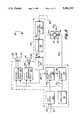
- FIG. 2is a block diagram of the improved UABD of the present invention illustrated in FIG. 1.
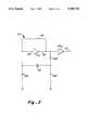
- FIG. 3is a schematic diagram of an exemplary oscillator circuit incorporated in the improved UABD illustrated in FIG. 2.
- FIG. 4is a schematic diagram of an exemplary amplifier/driver circuit incorporated in the improved UABD illustrated in FIG. 2.
- FIG. 5is a schematic diagram of an exemplary voltage amplifier circuit incorporated in the improved UABD illustrated in FIG. 2.
- FIG. 6is a schematic diagram of an exemplary demodulator circuit incorporated in the improved UABD illustrated in FIG. 2.
- FIG. 7is a schematic diagram of an exemplary filter circuit incorporated in the improved UABD illustrated in FIG. 2.
- FIG. 8is a schematic diagram of an exemplary automatic level control circuit incorporated in the improved UABD illustrated in FIG. 2.
- FIG. 9is a schematic diagram of an exemplary test circuit incorporated in the improved UABD illustrated in FIG. 2.
- FIG. 10is a schematic diagram of an exemplary comparator circuit incorporated in the improved UABD illustrated in FIG. 2.
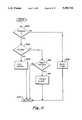
- FIG. 11is a flow chart diagram illustrating the detection of certain component failures in the improved UABD illustrated in FIG. 2
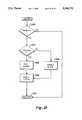
- FIG. 12is a flow chart diagram illustrating the detection of a large bubble and certain component failures in the improved UABD illustrated in FIG. 2
- FIG. 13is a flow chart diagram illustrating the detection of microbubbles in the improved UABD illustrated in FIG. 2
- FIG. 14is a top perspective view of the tubing holder of the present invention with transducer mounting blocks in place.
- FIG. 15is a bottom perspective view of the tubing holder shown in FIG. 14 with transducer mounting blocks removed.
- FIG. 16is an exploded top perspective view of the transducer mounting blocks of the tubing holder shown in FIG. 14 with the housing omitted.
- FIG. 17is a sectional view taken substantially at line 17--17 in FIG. 16.
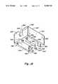
- FIG. 18is a sectional view taken substantially at line 18--18 in FIG. 14 illustrating the tube partially inserted into the tubing holder.
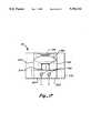
- FIG. 19is the sectional view of FIG. 18 illustrating the tube inserted into and retained by the tubing holder.
- UBDultrasonic air bubble detector
- aspects of the present inventionmay be applied to the detection of other inclusions in liquids, such as the detection of solid inclusions. It will be further appreciated by those having skill in the art that the invention is applicable to other signal types, such as infrared, visible and ultraviolet light, radiation or radio frequency energy, which are differently attenuated by a liquid and the inclusions to be detected.
- an acute care artificial kidney apparatus 20includes the UABD 22 of the present invention and two microprocessors 24, 26 for monitoring and controlling the acute care artificial kidney apparatus 20.
- the monitor microprocessor 24 and the control microprocessor 26are complementary units which communicate 28 with each other to compare various operating parameters of the artificial kidney apparatus 20, thus guarding against a single point component failure causing patient injury.
- the UABD 22incorporates a bubble detector circuit 30 and a tubing holder 32 for transmitting and receiving an ultrasonic signal through a tube 34 through which blood 36 is flowing.
- the tube 34is typically flexible plastic tubing that is part of a disposable tubing kit used in a blood processing system.
- the tubing holder 32comprises a first or transmitter mounting block 38 into which a piezoelectric ultrasonic transmitting transducer 40 is mounted and a second or receiver mounting block 42 into which a piezoelectric ultrasonic receiving transducer 44 is mounted.
- the piezoelectric transducers 40,44provide an efficient method for electrical to ultrasonic and ultrasonic to electrical energy conversion. Ultrasound emitted by the transmitting transducer 40 is sent through the tube 34 and blood 36 and is detected by the receiving transducer 44. The tube is held between the two transducers 40, 44 by the mounting blocks 38, 42 of the tubing holder 32.
- the bubble detector circuit 30generates an electrical drive signal 46 which drives the transmitting transducer 40.
- the transmitting transducer 40vibrates mechanically in response to the drive signal 46 causing an ultrasonic signal to pass through the tube 34 and blood 36.
- the ultrasonic signalcauses the receiving transducer 44 to vibrate mechanically producing an electrical received signal 48.
- the received signal 48is related to the bubble size.
- the bubble detector circuit 30receives the received signal 48 from the receiving transducer 44 in inverse proportion to the air in the blood 36.
- the bubblescause reductions in the received signal 48 that range from about 5%, for very small bubbles, to almost 100% for much larger bubbles.
- Small bubbles of about 1 ⁇ L in volume (0.58 mm diameter)produce ultrasound signals that correspond to about 12% of the normal quiescent ultrasonic signal.
- the received signal 48is interpreted by the bubble detector circuit 30 to create a plurality of output signals 50, 52, 54, 56, 58 which are then transmitted to the monitor microprocessor 24 and control microprocessor 26.
- the microprocessorscan each generate a test initiation signal 60, 62 which simulates the occurrence of a bubble and verifies that the bubble detector circuit 30 is functioning properly.
- the entire bubble detector circuit 30can be tested. Both large and small bubble conditions can be simulated from commands sent by both of the microprocessors 24, 26. The commands produce signals that emulate those produced by actual bubbles. Problems in the circuit may then be detected during the test.
- the bubble detector circuit 30includes an oscillator circuit 70 which generates a 2.45 megahertz (MHz) timing signal 72 at relatively low power levels.
- the timing signal 72is amplified by an amplifier/driver circuit 74 which produces the necessary 2.45 MHz, relatively high power level, drive signal 46 necessary to drive the transmitting transducer 40 of the tubing holder 32.
- the ultrasonic sound transmitted through the tube 34 and blood 36is received by the receiving transducer 44.
- the received signal 48is conducted to a voltage amplifier circuit 76 which amplifies the received signal and conducts an amplified signal 78 to a demodulator circuit 80.
- the demodulator circuit 80produces a DC rectified signal 82 proportional to the amplified signal 78 which is in turn filtered by a filter circuit 84 to produce a filtered signal 86 having a constant average voltage level, preferably approximately 2.5 volts.
- the average filtered signal 86 levelis controlled by an automatic level control (ALC) circuit 88 which produces a control signal 90 that adjusts the drive signal 46 from the amplifier/driver circuit 74 to maintain the average level of the filtered signal 86 at approximately the desired constant voltage level.
- ALCautomatic level control
- the ALC circuit 88compensates for variations in the detection environment such as transmitting transducer sound output variation, tube 34 material changes, receiving transducer 44 sensitivity variations and component tolerances. The ALC circuit 88 thus tends to assure that the UABD always reacts the same to particular bubble sizes.
- the filtered signal 86 from the filter circuit 84is split and fed into two similar voltage comparator circuits 92, 94.
- a monitor comparator circuit 92produces the output signals 50, 52, 54 for use by the monitor microprocessor 24 (FIG. 1) and the control comparator circuit 94 produces output signals 56, 58 for use by the control microprocessor 26 (FIG. 1).
- the redundant comparator circuits 92, 94facilitate safe operation of the UABD 22 and the artificial kidney apparatus 20 (FIG. 1) in the event of a component failure.
- Each comparator circuit 92, 94delivers three separate logic signals.
- a trouble signal 50, 96corresponds to certain failures in the detector circuit 30, and will change state whenever the ultrasound signal goes above an acceptable limit 32.
- a bubble signal 52, 98produces a logic output whenever a large, 10 ⁇ L or greater, bubble is detected or when there is no tube 34 installed in the tubing holder.
- a microbubble signal 54, 58produces a logic swing whenever a small, 1.0 ⁇ L or greater, is detected.
- the microprocessors 24, 26count the number of microbubble events through a fixed time frame, e.g., one minute, and shut down the artificial kidney apparatus 20 (FIG. 1) if a predetermined number of events per unit time is exceeded.
- the trouble signal 96 and the bubble signal 98 from the control comparator circuit 94are tied together to form a single air signal 56.
- the microprocessors 24, 26(FIG. 1) periodically monitor the bubble counts. If a sufficient number of microbubble clock pulses are detected for the artificial kidney apparatus's 20 specific fluid pumping rate, one of the microprocessors 24, 26 will activate an alarm and shut down the artificial kidney apparatus 20. Likewise, if one of the microprocessors 24, 26 (FIG. 1) receives a large bubble signal 52, 98 or a trouble signal 50, 96 it will activate an alarm and command the artificial kidney apparatus 20 to stop.
- a test circuit 100is provided to generate a simulation signal 102 to simulate the presence of a bubble or a series of microbubbles upon command from the monitor microprocessor 24 or the control microprocessor 26 by interfacing with the ALC circuit 88.
- the piezoelectric sound emitting transmitting transducer 40is driven by a constant frequency, variable amplitude driver signal 46 produced by the oscillator circuit 70 and amplifier driver circuit 74 as will be described by reference to FIGS. 3 and 4.
- the oscillator circuit 70illustrated in FIG. 3, comprises by a quartz crystal oscillator.
- the oscillatorcomprises a high speed unbuffered C-MOS inverter, preferably one section of a 74HCU04 integrated circuit (IC).
- the unbuffered inverteris used to promote linear operation of the oscillator circuit 70.
- An "AT" cut quartz crystal 112that is designed for parallel resonant operation is connected to the inverter input 114.
- the oscillator circuit 70is a variation of the conventional "Pierce” oscillator.
- a resistor 118preferably 1 megaOhms (M ⁇ ) connected from the output 116 to the input 114 of the inverter 110 biases the inverter into the linear one half supply point.
- a suppression resistor 120preferably 2.12 kiloOhms (k ⁇ ) connected between the output 116 and the crystal 112 suppresses spurious high frequency oscillations and isolates the output from the crystal 112. With the suppression resistor 120 installed, the inverter output 116 has a square wave form signal. The suppression resistor 120 is picked to be roughly the reactance of the quartz crystal 112 at its resonant frequency.
- the signal from the input 114 to the output 116 of the inverteris phase shifted 180 degrees by the logic inversion.
- the quartz crystal 112appears as a large inductance, since it is operated in the parallel resonance mode.
- the addition of a capacitor 122 at the input and a capacitor 124, each preferably about 22 picoFarads (pF) at the output of the inverter circuitproduce a pi network. Such a network provides an additional 180 degree phase shift to sustain oscillation.
- the load capacitanceis usually specified by the quartz crystal manufacturer.
- the output signalis then buffered by a second C-MOS logic inverter 126, preferably contained within the same 74HCU04 IC package, to produce the timing signal 72.
- the timing signal 72 output of the oscillator 70is a 5 volt peak-to-peak square wave signal.
- the operation of the power amplifier/driver circuit 74is illustrated in FIG. 4.
- the 5 volt peak-to-peak square wave timing signal 72 that emerges from the oscillator circuit 70 (FIG. 2)is fed to the input 128 of an inverting power driver 130, preferably an ICL7667 IC.
- the power driver 130converts the 5 volt peak to peak signal into a 12 volt peak-to-peak square wave output signal.
- the power driver 130is specifically selected to drive power field effect transistors (FETs). Since power FETs are noted for their high input capacitance, the ICL7667 has been specifically designed to supply a load with high peak currents.
- the ICL7667can drive loads with peak currents up to 1.5 amps.
- the high drive currentallows an FET device to be turned on and off in less than 50 nanoseconds.
- An inductor 129preferably 470 microHenries ( ⁇ H), and a capacitor 131, preferably 0.1 microFarads ( ⁇ F), are connected to the power pin 133 of the power driver 130.
- the inductor 129 and capacitor 131are connected as a conventional L-section low pass filter to block the high frequency timing signal 72, preventing it from entering the +12 volt power supply.
- the output 132 of the power driver 130is fed to a complementary power FET circuit, which consists of one N-channel FET 134, preferably ZVN2106A, and one P-channel FET 136, preferably ZVP2106A.
- the drain terminals 138, 140 of the two FETs 134, 136are connected together.
- the N-channel FET 134is turned on during the low-to-high transition of the power driver's 130 output signal, while the P-channel FET 136 is turned on during the high-to-low transition.
- a capacitor 142, preferably 0.1 ⁇ F connected between the gates 144, 146 of the FETs 134, 136couples the output of the power driver 130 to the P-channel FET 136.
- a resistor 148preferably 1 k ⁇ connected between the gate 146 and source 150 of the P-channel FET 136 is used to bias the P-channel FET 136 into the off state.
- Each FET 134, 136requires a minimum voltage threshold of about 3 volts between the gate and source to begin turning on. Therefore the 12 volt voltage swing from the power driver 130 insures each FET 134, 136 will be turned on hard, keeping the drain-to-source resistance low.
- the variable voltage ALC signal 90is connected to the source of the P-channel FET 136.
- the source of the n-channel FET 134is connected to circuit ground 154.
- the P-channel FET 136When turned on fully, the P-channel FET 136 provides a low resistance path from the ALC signal 90 supply voltage to the output. Conversely, when turned on, the N-channel FET 134 provides a low resistance path from the output to circuit ground 154.
- the two FET 134, 136 combinationgenerates a square wave output signal that swings from the voltage level of the ALC signal 90 to ground with low loss. Since the upper P-channel FET source voltage is controlled by the ALC signal 90 from the ALC circuit 88, the transmitting transducer 40 (FIG.
- peak-to-peak drive signal 46can be varied over a wide range.
- the upper drive voltageis restricted by power dissipation of the transmitting transducer 40 (FIG. 2).
- the lower voltage levelcan, in theory, be as low as a few millivolts.
- the output signalhas a square wave form, with fast rise and fall times. Since the transmitting transducer 40 (FIG. 2) has a high capacitance, up to 1000 pF, an inductor 156 preferably 5.6 ⁇ H, and a capacitor 157, preferably 0.1 ⁇ F are placed between the FETs 134, 136 and the transducer 40 (FIG. 2).
- the capacitor 157isolates the transmitting transducer 40 from any DC voltage delivered by the amplifier/driver circuit 74.
- the inductor 156limits the peak currents that would otherwise flow through the transducer 40 if a direct connection were made.
- the voltage rise and fall timesare also limited by the inductor 156.
- the inductor 156thereby reduces the broadband radio signals that would otherwise be emitted, if a direct connection were made to the FETs 134, 136.
- the drive signal 46 that is produced across the transducer 40(FIG. 2) resembles a pure sine wave with minimum harmonics.
- the peak-to-peak voltage produced by the inductor 156 across the transducer 40 (FIG. 2)is slightly greater than the peak-to-peak drive voltage. With an 11 volt peak-to-peak output from the two FETs 134, 136 the voltage seen across the transmitting transducer can exceed 15 volts peak-to-peak.
- the power dissipation at the transmitting transducer 40is less than 0.25 watts.
- the inductor 156limits the current that can be delivered by the amplifier/driver circuit 74 thus providing short circuit protection. With the inductor 156 in place the drive signal 46 can be continuously shorted to ground with no ill effects on the bubble detector circuit 30.
- the ultrasound signal voltage amplifier circuit 76will be described in conjunction with FIG. 5.
- the ultrasound voltage received signal 48produced by the piezoelectric receiver transducer 44 (FIG. 2), is amplified using a high frequency operational amplifier 160.
- the high frequency amplifieris preferably an AD829 operational amplifier IC chosen for its wide bandwidth, linearity and stability.
- An amplifier gain of 40is needed to boost the weak received signal 48 to produce an amplified signal 78 having an amplitude of 3 volts peak-to-peak. At 3 volts the raw ultrasound signal can be efficiently demodulated to extract the sometimes small bubble signals.
- the amplifier's 160 unity gain bandwidthhas to be greater than about 80 MHz.
- the AD829 operational amplifier IChas a unity gain bandwidth of 120 MHz.
- the amplifier 160 ICis connected as a modified non-inverting amplifier circuit.
- a blocking capacitor 161preferably 0.01 ⁇ F, interconnects the received signal 48 and a non-inverting input 162 of the amplifier 160.
- the blocking capacitor 161AC couples the non-inverting input 162 to the received signal, blocking any DC component of the received signal 48 and attenuating any stray low frequency components of the received frequency, such as 60 Hertz (Hz) hum, while passing the desired high frequency component of the received signal 48 without significant attenuation.
- HzHertz
- the received signal 48is fed directly to the non-inverting input 162 of the amplifier 160, while the amplifier's 160 inverting input 164 is supplied with a signal that is generated by feeding back a small amount of the amplifier's output 166.
- a two resistor 168, 170 voltage dividerwould determine the amount of signal fed back to the inverting input 164 and would therefore determine the voltage gain of the amplifier circuit 76.
- a first resistor 168preferably 4.32 k ⁇ , is connected between the amplifier 160 output 166 and the inverting input 164 and a second resistor 170, preferably 100 Ohms ( ⁇ ) is connected between the inverting input and circuit ground 154.
- the conventional non-inverting circuithas been modified so the amplifier has a high gain for the high frequency ultrasound signal and a gain of only one for DC.
- a capacitor 172preferably 0.01 ⁇ F, in series with the second resistor 170, interposed between the resistor 170, and circuit ground 154 provides the needed DC isolation.
- the modified non-inverting circuitallows the amplifier's gain to be controlled by a single resistor, without disturbing the DC bias point.
- the capacitor 172insures that the amplifier preferentially amplifies only high frequency signals.
- Two resistors 174, 176are connected to the non-inverting input 162 to form a second voltage divider network that biases the amplifier 160 to about the half way point between the +12 volt and the -5 volt supplies, approximately +3.5 volts.
- the biasingmaximizes the amplifier's peak-to-peak output voltage swing and moves the normal operating point away from -5 volt power supply.
- the amplifier's gainis set at about 40.
- a phase compensation capacitor 178preferably 10 pF, is added and is connected to the amplifier's 160 compensation pin 180.
- the capacitor 178 valueis chosen to keep the circuit 76 free of spurious oscillations, without reducing the overall gain.
- the signal demodulator circuit 80will be described by reference to FIG. 6.
- the demodulator circuit 80comprises a conventional half wave voltage doubling rectifier circuit operative on the amplified signal 78.
- the demodulator circuit 80converts the amplitude modulated 2.45 MHz amplified signal 78, that emerges from the amplifier circuit 76 (FIG. 2), into the DC voltage rectified signal 82.
- the demodulator 80 circuitcomprises a first diode 186, a second diode 188, a first capacitor 190, a second capacitor 192 and a resistor 194 connected in a well known configuration to form the half wave voltage doubling rectifier circuit.
- the first and second capacitors 190, 192are each preferably 0.01 ⁇ F and the resistor 194 is preferably 10 k ⁇ .
- the DC voltage level of the rectified signal 82will fluctuate downward whenever an air bubble passes between the ultrasound transducers.
- the diodes 186, 188are preferably Schottky diodes, 1N5818. Schottky diodes have a lower voltage drop (about 0.25 volts) than the more conventional signal diodes (about 0.6 volts) and when used in the voltage doubler circuit will produce a DC voltage rectified signal 82 of about 2.5 volts from a 2.8 volt peak-to-peak amplified signal 78.
- the capacitor 192 and resistor 194form a conventional low pass filter network.
- the values of the capacitor 192are selected to filter out most of the 2.45 MHz carrier without attenuating signals associated with bubbles.
- the filter circuit 84will be described by reference to FIG. 7. To remove the 2.45 MHz carrier signal that may remain, a conventional second order Butterworth low pass active filter 84 is used after the demodulator circuit 80.
- the active Butterworth type low pass filter 84is made using a low frequency operational amplifier 204, preferably an LF411 IC.
- the filter circuit 84does not provide any additional gain, it does buffer the signal so it can be routed to many other active circuits without being attenuated.
- the 3 decibel (db) frequency knee of the Butterworth filteris set at about 1 kilohertz. Such a frequency is based on the highest expected frequency of interest, associated with bubbles passing through the detector at the maximum flow rate of 180 milliliters (mL) per minute.
- the second order Butterworth filterattenuates signals higher than 1 kHz with a 12 db per octave slope.
- the ALC circuit 88maintains a constant average signal level, as seen at the filtered signal 86 output of the filter circuit 84 as will be described in conjunction with FIG. 8. Because the voltage input to the comparator circuits 92, 94 (FIG. 2) is held to a constant average value by the ALC circuit 88 the sensitivity of detection will remain constant. The ALC circuit 88 controls the voltage fed to the transducer amplifier/driver circuit 74 so the filtered signal 86 is maintained at a constant average signal level. Factors in the bubble sensing environment that may influence the average signal level can therefore be compensated for. With the components selected, the filtered signal 86 output from the filter circuit 84 should always average very close to 2.5 volts.
- the ALC circuit 88consists of an inverting integrator 206 and an ALC voltage amplifier 208.
- the conventional inverting integrator 206comprises an operational amplifier 210, preferably an LF412A IC, that compares the filtered signal 86 output voltage from the filter circuit 84 (FIG. 2) with a DC reference voltage 214.
- a feedback capacitor 212preferably 1.0 ⁇ F, is connected between an output 207 of the operational amplifier 210 and an inverting input 209 of the operational amplifier 210.
- the DC reference voltage 214is generated by voltage divider network made up of two resistors 216, 218, each preferably 10 k ⁇ and a capacitor 220, preferably 0.01 ⁇ F and is connected to a non-inverting input 211 of the operational amplifier.
- the voltage used by the divider networkis derived from a first precision voltage reference source 222.
- the first voltage reference source 222is generated by a precision voltage source IC (not shown), preferably a REF-02 IC, which provides a very precise 5 volt output.
- the integrator's 206 output signal 224slowly adjusts upward if the received average filtered signal 86 voltage level is less than the reference voltage 214 and adjusts downward if the filtered signal 86 is greater than the reference voltage 214.
- the effectis a conventional negative feedback control circuit that has integral action and a slow response time.
- the integrator circuit 206permits a high gain to insure control accuracy but has an intentionally slow response time.
- the slow responseallows the sudden level changes associated with bubbles to be ignored by the ALC circuit 88.
- the response timeis selected to be slower than the signals of interest caused by bubbles by about ten times in the preferred embodiment.
- the filtered signal 86is connected to the inverting input 209 of the operational amplifier 210 through a first response time determining resistor 213 and a second response time determining resistor 215.
- the first resistor 213is connected in series between the filtered signal 86 and the inverting input 209.
- the first response time determining resistor 213, preferably 1 M ⁇ , and the feedback capacitor 212, preferably 1.0 ⁇ Festablish a relatively slow one second response time.
- the second response time determining resistor 215, preferably 100 k ⁇ ,is connected in series with a diode 217, preferably 1N4148, and the series combination is connected in parallel with the first resistor 213.
- the second resistor 215is activated only during large changes in the filtered signal 86, such as from a large bubble, to produce a relatively faster 0.1 second response time.
- a slow positive response timeis needed to ignore sudden changes in the filtered signal 86 level due to bubbles.
- a faster negative response timeis allowed to restore the initial level of the filtered signal 86.
- the asymmetrical reaction of the integrator 86 to signal changesminimizes distortion of bubble signal amplitudes and minimizes over correction voltages.
- the faster response time to large signal changesis especially useful when the artificial kidney apparatus 20 (FIG. 1) is initially turned on and when the tube 34 (FIG. 1) is installed in the tubing holder 32 (FIG. 1). Under these conditions the ALC circuit 88 quickly reestablishes normal UABD operation.
- the output 224 of the integrator 206is fed to the ALC voltage amplifier 208.
- the ALC voltage amplifier 208comprises a conventional non-inverting operational amplifier 226, preferably a part of the same LF412A IC package as the integrator operational amplifier 210.
- the output of the operational amplifier 226is connected to the base 228 of an NPN Darlington transistor 230, preferably 2N6725, through a Zener diode 232, preferably 1N4728A.
- the Darlington transistor 230forms a transistor buffer circuit which allows more current to be controlled than would be possible using the operational amplifier 226 alone.
- a feedback resistor 229preferably 10 k ⁇ , connected between the emitter 231 of the Darlington transistor 230 and the inverting input 233 of the operational amplifier 226 and an additional resistor 235, preferably 10 k ⁇ , connected between the inverting input of the operational amplifier 226 and circuit ground 154 determine the gain of the ALC voltage amplifier 208.
- the Zener diode 232provides a voltage level shift. The level shift is needed to compensate for the inability of the operational amplifier 226 to swing to both the plus and minus supply voltages. Typically, with a +12 volt and a -5 volt supply the operational amplifier 226 will only be able to swing from +10 volts to -3 volts.
- the base 228 of the Darlington transistor 230can be fed with a voltage that swings from 0 volts to 12 volts.
- the actual voltage swing fed to the transducer amplifier/driver circuit 74is from 0 volts to about 11 volts.
- a buffer capacitor 237, preferably 4.7 ⁇ F connected between the emitter 231 of the Darlington transistor 230 and circuit ground 154provides a low source impedance to the amplifier/driver circuit 74 (FIG. 2).
- An inductor 239preferably 470 ⁇ H, and a capacitor 241, preferably 0.1 ⁇ F, form a conventional L-section low pass filter between the emitter 231 of the Darlington transistor 230 and the ALC signal 90.
- the inductor 239 and capacitor 241prevents the high frequency 2.45 MHz signals from interfering with the ALC circuit 88.
- the ALC circuit 88With the ultrasonic amplifier gain set at 40 and a wide ultrasonic drive voltage swing, the ALC circuit 88 has a compensation range of over 30 db (30:1).
- the test circuit 100interacts with the ALC circuit 88 to permit generating sudden level changes in the ultrasonic signal transmitted by the transmitting transducer 40 (FIG. 2) to simulate various sizes of bubbles for testing purposes.
- the sudden level changesare detected by the voltage amplifier circuit 76 (FIG. 2), the demodulator circuit 80 (FIG. 2), the filter circuit 84 (FIG. 2) and the comparator circuits 92, 94 (FIG. 2) as bubble signals.
- the simulated signalscan be used during artificial kidney apparatus 20 (FIG. 1) testing and will test the operation of the bubble detector circuit 30 (FIG. 2).
- the output of the integrator circuitis first attenuated by factor of two by a first attenuation resistor 232, preferably 10 k ⁇ , connected in series between the output 224 of the integrator 206 and the non-inverting input 237 of the operational amplifier 226 of the ALC voltage amplifier 208.
- a second attenuation resistor 239preferably 20 k ⁇ , is connected between circuit ground 154 and the non-inverting input 237 of the operational amplifier 226. The signal loss is compensated for by setting the voltage amplifier's 226 gain at two by selection of the gain determining resistors 229, 235.
- a third attenuation resistor 234, preferably 15.8 k ⁇ ,is included in the circuit and can be switched into the circuit using a monitor test FET 238, preferably 2N7000, that connects the resistor 234 between the non-inverting input 237 of the operational amplifier 226 of the ALC voltage amplifier 208.
- a fourth attenuation resistor 236, preferably 3.92 k ⁇ ,is included in the circuit and can be switched into the circuit using a control test FET 240, preferably 2N7000, that connects the resistor 236 between the non-inverting input 237 of the operational amplifier 226 of the ALC voltage amplifier 208.
- the FET switchesWhen activated by a logic level test signal 60, 62 swing, the FET switches change the ratio of the attenuation network and thus the output voltage of the amplifier 226.
- the resistors 234, 236decrease the amplifier's 226 output voltage by a fixed ratio, thus lowering the voltage levels of the ALC signal 90 and the transducer drive signal 46 (FIG. 2) by the same proportion, regardless of the actual voltage used to maintain an average received ultrasound level.
- a small 1 ⁇ L microbubblecan be simulated by energizing the monitor test signal 60, thereby turning on the monitor test FET 238 causing a sudden 24% drop in the normal drive voltage, which forces the received signal 48 (FIG. 2) to also drop by 24%.
- a 10 ⁇ L bubblecan be simulated by activating control test signal 62, thereby turning on the control test FET 240 dropping the drive voltage by 56%. Since the voltage change, during activation of either of the two FETs 238, 240 occurs after the slow responding integrator, the sudden drive voltage drop will produce a signal similar to a signal produced by a bubble.
- a resistor 242preferably 20 k ⁇ , and capacitor 246, preferably 0.047 ⁇ F, connected as a conventional L-section low pass filter network is installed between the attenuation resistors 232, 234, 236, 239 and the non-inverting input 237 of the operational amplifier 226 at the input of the voltage amplifier 226.
- the networkslows down the level change and makes the signals produced at the ultrasound receiver appear more like actual bubble signals, that normally have finite rise and fall times.
- the two components usedresult in a time constant is about 2.3 ms.
- FIG. 10illustrates the monitor comparator circuit 92.
- the control comparator circuit 94(FIG. 2) is substantially identical to the monitor comparator circuit 92 except for those differences specifically described below.
- the monitor comparator circuit 92feeds signals 50, 52, 54 to the monitor processor 24 (FIG. 1) while the control comparator circuit 94 (FIG. 2) feeds signals 56, 58 (FIG. 1) to the control processor 26 (FIG. 1). Should a component failure occur in one comparator circuit 92, 94 (FIG. 2), the other circuit would still be able to operate correctly. However, since both comparator circuits 92, 94 (FIG. 2) should operate in a similar fashion, disagreement between the two circuits may be detected by the communication 28 (FIG. 2) between the two microprocessors 24, 26 (FIG. 1) and could force an alarm or shut-down of the artificial kidney apparatus 20 (FIG. 1).
- Each voltage comparator circuitcomprises three comparators 250, 252, 254.
- Each comparatoris a voltage comparator, preferably an LM339A IC, which compares the filtered signal 86 with a reference voltage derived from the precision voltage source 222.
- the control comparator circuit 94has a separate associated second precision voltage source IC (not shown), so that a failure of a precision voltage source IC will cause a disagreement between the microprocessors 24, 26 (FIG. 1) as described above.
- a first comparator 250 of the comparator circuit 92detects component failures in the bubble detector circuit 30 (FIG. 2).
- a second comparator 252detects the presence of relatively large bubbles in the tube 34.
- the third comparator 254detects the presence of microbubbles in the tube. The presence of each microbubble is transmitted to the corresponding microprocessor so that the microprocessor can count the bubbles and determine the number encountered within a discrete period of time.
- a pull-up resistor 256, 258, 260preferably 2.21 k ⁇ connects each comparator 250, 252, 254 output 262, 264, 266 to +5 volt power supply VCC to provide a standard transistor-transistor logic output swing of 5-to-0 and 0-to-5 volts.
- the filtered signal 86is connected to the inverting input 268 of the first comparator 250 through an isolation resistor 270.
- the 5 volt precision supply 222is connected to the non-inverting input 272 of the first comparator through voltage divider network made up of two resistors 274,278, selected so that the reference voltage at the non-inverting input of the first comparator is 2.8 volts.
- the comparator output 262is connected as the trouble signal 50 to the microprocessor 24 (FIG. 1).
- the first comparator non-inverting inputis tied to the second precision voltage source through a pull-up resistor only, preferably 10 k ⁇ , so that the reference voltage is 5 volts.
- the filtered signal 86is connected to the non-inverting input 278 of the second comparator 252 through an isolation resistor 280.
- the 5 volt precision supply 222is connected to the non-inverting input 282 through a voltage divider network made up of two resistors 284, 286 selected so that the reference voltage at the non-inverting input 282 of the second comparator 252 is 1.2 volts.
- a feedback resistor 288, preferably 1 M ⁇ , connected between the non-inverting input 278 and the output 264provides positive feedback.
- the comparator output 264is connected as the bubble signal 52 to the microprocessor 24 (FIG. 1) through a D flip-flop latch 265, preferably 74HC74 IC, associated with the microprocessor 24.
- the D flip-flop latch 265 output 267communicates the occurrence of a bubble to the microprocessor 24 and the microprocessor 24 is connected to reset 267' D flip-flop latch 265.
- the third comparator's 254 inverting input 290is connected to the filtered signal 86 through an isolation resistor 292.
- the non-inverting inputis connected to the 5 volt precision supply 222 through a voltage divider network made up of two resistors 296, 298 selected so that the reference voltage at the non-inverting input is 2.2 volts.
- a feedback resistor 300preferably 1 M ⁇ , connected between the output 266 and non-inverting input 294 provides positive feedback.
- the output 266 of the third comparator 254is connected to the input 302 of a standard J-K flip-flop, preferably a 74HC76 IC.
- the K input 306, inverting clear input 308, and inverting preset inputs 310are all held at a logical high state by virtue of being connected to the +5 volt logic power supply VCC.
- the clock input 312is connected to the 2.45 MHz timing signal 72 from the oscillator circuit 70 (FIG. 2).
- the flip-flop 304 output 314is connected as the microbubble signal 54 to the microprocessor 24 (FIG. 1) through a counter 305, preferably 82C54 IC, associated with the microprocessor 24.
- the counter 305accumulates pulses proportional to the amount of time microbubble signals 54 are detected and makes that information 307 available as digital data to the microprocessor 24 (FIG. 1).
- the trouble signal 96 (FIG. 2) from the first comparator and the bubble signal 98 (FIG. 2) from the second comparatorare connected together to form a single air signal 56 (FIG. 1) to the control microprocessor 26 (FIG. 1).
- the air signal 56is connected to the control microprocessor 26 (FIG. 1) through a D flip-flop latch (not shown) associated with the microprocessor 26 (FIG. 1), in the same manner as the bubble signal 52 is connected to the monitor microprocessor 24 (FIG. 1).
- the output 262 of the first comparator 250 and the trouble signal 50are at a logical high state, indicating no trouble in the bubble detector circuit 30; the output 264 of the second comparator 252 and the bubble signal 52 are at a logical high state indicating no large bubbles, and the output 266 of the third comparator 254 is at a logical low state.
- the logical low state of the third comparator 254 outputholds the J input 302 of the J-K flip-flop 304 at a low logical state which in turn holds the non-inverting output 314 and microbubble signal 54 at a low logical state, indicating the absence of microbubbles.
- the comparatorswill toggle whenever the filtered signal 86 deviates above or below the threshold voltage used by each comparator 250, 252, 254 circuit.
- the first comparator 250toggles whenever the filtered signal 86 swings higher than 2.8 volts causing the trouble signal 50 to go to a low logic state, indicating to the microprocessor 24 (FIG. 2) that equipment failure has occurred. Such a condition might occur if a component failed in the ALC circuit 88.
- the first comparatortoggles when the filtered signal 86 voltage swings above 5 volts.
- the second comparator 252changes state when the ultrasound signal drops to 1.2 volts. That condition would occur when the plastic tubing was not installed into the sensor assembly, upon a failure occurring in the ALC circuit or when a large bubble is sensed. This causes the bubble signal 52 to go to a low logic state and indicating a bubble.
- the low logic statesets the D flip-flop latch 265 output 267 to a logical high state, signaling the monitor microprocessor 24 (FIG. 1) of the occurrence of the bubble.
- the flip-flop 265stays set until reset 267' by the microprocessor 24 (FIG. 1).
- the output 266 of the third comparator 254goes to a logical high level indicating the presence of a microbubble. It is undesirable to shut down the artificial kidney apparatus 20 upon the occurrence of an isolated microbubble.
- the parameter of interest in the case of microbubblesis the volume of air per unit time, a maximum allowable of 1 cubic centimeter per minute delivered past the detector in the form of microbubbles in the preferred embodiment. A running average is therefore determined by the microprocessor 24 to determine when the number of microbubbles has reached a critical level.
- the microprocessors 24, 26control the rate of blood flow through the tube.
- a stream of clock pulses at a pulse frequency of 1.22 MHzis sent to the counter 305.
- the counter 305accumulates the number of clock pulses and compares them to a time reference. The number of clock pulses counted would then be proportional to the length of time the small bubble comparators were activated.
- the microprocessor 24By frequently monitoring the number of pulses counted, and taking into account the rate of blood flow in the tube 34 (FIG. 1) the microprocessor 24 (FIG. 1) can ascertain the approximate volume air contained in the microbubbles.
- the microprocessor 24 (FIG. 1)can determine the blood flow rate and compensate for the expected changes in bubble signals as the blood flow rate changes.
- the J-K flip-flop 304serves two functions. It provides a fast rise and fall time signal. It also turns on and off the timing signal 72 signal that is derived from the oscillator circuit 70. When triggered by the third comparator 254, the flip-flop 304 produces an output signal 314 that is 1/2 the frequency of the 2.45 MHz transducer clock signal. When the "J" input of the IC goes to a high logical value the flip-flop turns into a simple one bit counter. The 2.45 MHz clock signal that is connected to the clock input is therefore divided by two and emerges as a 1.22 MHz signal at the output 314 whenever the third comparator 254 is activated.
- the 1.22 MHz frequencyis selected to be high enough so that substantially all detected microbubbles result in at least one clock pulse at all expected flow rates, yet low enough that the registers of the counter 305 are not filled between times when the microprocessor 24 (FIG. 1) reads the counter 307.
- each microprocessor 24, 26 (FIG. 1)sequentially polls its associated signals 50, 52, 54, 56, 58 (FIG. 1) periodically, every 25 milliseconds in the preferred embodiment.
- the microprocessors 24, 26 (FIG. 1)could operate on an interrupt basis, processing the signals 50, 52, 54, 56, 58 (FIG. 1) from the bubble detector circuit 30 (FIG. 1) only when they change state.
- the monitor microprocessor 24polls the trouble signal 50 (FIG. 10) to determine if a logical low state is present, indicating a failure as described above (at 500). If there is no failure indicated, a software trouble signal timer is reset to zero (at 502) and the poll of the trouble signal 50 (FIG. 10) is terminated (at 504) until the next polling cycle.
- the microprocessor 24(FIG. 1) ascertains if a test of the trouble signal 50 (FIG. 10) function is in progress (at 506). If such a test is in progress, the monitor determines that the test has been passed (at 508) and terminates the poll of the trouble signal 50 (FIG. 10) (at 504) until the next polling cycle.
- the monitor microprocessor 24(FIG. 1) reads the software trouble signal timer to determine if the timer has timed out (at 510).
- the trouble signal 50(FIG. 10) may go momentarily to a logical low state under certain conditions not indicative of a failure, such as a filtered signal 86 (FIG. 10) voltage overshoot at the end of the passage of a large bubble through the tube 34 (FIG. 1).
- the software trouble timerprevents nuisance alarms by ensuring that a trouble state exists for a predetermined time, 1.5 sec in the preferred embodiment, before activating an alarm.
- the software timeris reset (at 502) when the trouble signal 50 (FIG. 10) returns to a logical high value, indicating no failure.
- the software trouble timerhas not expired the timer is permitted to continue running and the poll of the trouble signal 50 (FIG. 10) is terminated until the next polling cycle. If, however, the software trouble timer has expired, a trouble alarm is activated (at 512), indicating UABD failure and the poll of the trouble signal 50 (FIG. 10) is terminated (at 504) until the next polling cycle.
- the trouble alarmmay activate audible and visual alarm indications and may shut down the artificial kidney apparatus 20 (FIG. 1).
- the monitor microprocessor 24polls the output 267 (FIG. 10) of the D flip-flop latch 265 (FIG. 10) to determine if a logical high state is present, indicating the passage of a large bubble through the tube 34 (FIG. 1) (at 520). If there is no large bubble indicated the poll of the D flip-flop latch 265 (FIG. 10), and thus the bubble signal 52 (FIG. 10), is terminated (at 522) until the next polling cycle.
- the microprocessor 24(FIG. 1) ascertains if a test of the bubble signal 52 function is in progress (at 524). If such a test is in progress, the monitor microprocessor 24 (FIG. 1) determines that the test has been passed (at 526), sends a reset signal 267' (FIG. 10) to the D flip-flop latch 265 (FIG. 10) (at 528) and terminates the poll of the output 267 (FIG. 10) of the D flip-flop latch 265 (FIG. 10), and thus the bubble signal 52 (FIG. 10) is terminated (at 522) until the next polling cycle.
- a bubble alarmis activated (at 530), indicating passage of a large bubble.
- the bubble alarmmay activate audible and visual alarm indications and may shut down the artificial kidney apparatus 20 (FIG. 1).
- the poll of the D flip-flop latch 265 (FIG. 10), and thus the bubble signal 52 (FIG. 10),is terminated (at 522) until the next polling cycle.
- the control microprocessor 26polls and interprets the air signal 56 (FIG. 1) by the same method that the monitor microprocessor 24 (FIG. 1) uses to poll and interpret the bubble signal 52 (FIG. 1).
- microbubblesmay appear in a more or less continuous cluster of mutually indistinguishable microbubble, known as a "string-of pearls."
- the volume of air contained in such a string of pearlsis a function of both the time that the string takes to pass through the tube 34 (FIG. 1) and the velocity at which it is moving. Since the parameter of interest is not the occurrence of a microbubble, but rather the volume of air in microbubble form per unit time to pass through the tube 34 (FIG. 1), it is necessary to account for these factors.
- the speed at which the microbubbles are movingis substantially determined by the blood flow rate, which is established by the microprocessor 24 (FIG. 1).
- the count accumulated in the counter 37 (FIG. 10) over a fixed period of timeindicates the time a string of microbubbles takes to pass through the tube 34 (FIG. 1).
- the monitor microprocessor 24(FIG. 1) examines the value of the blood flow rate through the tube 34 (FIG. 1) (at 540). The microprocessor 24 (FIG. 1) then determines if the flow rate has changed since the last polling cycle (at 542). If the blood flow rate has changed the microprocessor 24 (FIG. 1) calculates a counts per microbubble factor, which is a constant divided by the blood flow rate (at 544). The constant is directly proportional to the pulse frequency and the assumed size of a microbubble.
- the constantis approximately 44.1 ⁇ 10 6 .
- the poll of the microbubble signal 54(FIG. 10) is terminated (at 504) until the next polling cycle.
- the microprocessor 24examines the microbubble counter 305 to ascertain the number of counts currently accumulated in the counter 305 (at 548). This value is compared to the value ascertained a predetermined time earlier, one minute in the preferred embodiment, and a difference calculated to ascertain the number of counts accumulated during the predetermined time period (at 550). The number of counts accumulated during the predetermined time period is then divided by the counts per microbubble to ascertain the number of microbubbles, and thus the total quantity of air in the form of microbubbles, to pass through the tube 34 (FIG. 1) during the predetermined time period (at 552).
- the number of microbubbles to pass through the tube during the predetermined time periodis then compared to an allowable number of microbubbles or total quantity of air per unit time, 1 mL/min in the preferred embodiment (at 554). If the allowable limit has not been equalled or exceeded the poll of the microbubble signal 54 (FIG. 10) is terminated (at 546) until the next polling cycle.
- the microprocessor 24(FIG. 1) ascertains if a test of the microbubble signal 54 (FIG. 10) function is in progress (at 556). If such a test is in progress, the monitor microprocessor 24 (FIG. 1) determines that the test has been passed (at 558) and terminates the poll of the microbubble signal 54 (FIG. 10) (at 546) until the next polling cycle.
- microbubble alarmmay activate audible and visual alarm indications and may shut down the artificial kidney apparatus 20 (FIG. 1).
- the control microprocessor 26polls and interprets the control microbubble signal 58 (FIG. 1) by the same method that the monitor microprocessor 24 (FIG. 1) uses to poll and interpret the monitor microbubble signal 54 (FIG. 1).
- control microprocessor 26blocks the actuation of a bubble alarm and activates the control test signal line 62 (FIG. 9) for a predetermined period of time, 0.6 second in the preferred embodiment, turning on the control test FET 240 (FIG. 9) to emulate a bubble.
- the bubble and air signal interpreting functions described abovethen detect the signals and determine if the bubble detector circuit has passed the test.
- the trouble functionis tested by performing a test of the bubble function. At the end of the bubble function test a short duration filtered signal 86 (FIG. 10) voltage overshoot will occur which will cause the trouble signal 50 (FIG. 10) to go the a low logical value for a short period of time. Failure to detect the voltage overshoot indicates that the trouble function is faulty.
- the monitor microprocessor 24(FIG. 1) blocks the actuation of a microbubble alarm and sends a series of sixteen cycles of a one Hz square wave signal on the monitor test signal line 60 (FIG. 9), turning on the monitor test FET 238 (FIG. 9) intermittently to emulate sixteen microbubble occurrences.
- the microbubble signal interpreting function described abovethen detects the signals and determines if the bubble detector circuit has passed the test.
- the alarmmay activate audible and visual alarm indications and may shut down the artificial kidney apparatus 20 (FIG. 1).
- the tubing holder 32 of the present inventionwill be described by reference to FIGS. 14 through 19.
- the tubing holder 32comprises a housing 320 into which the two transducer mounting blocks 38, 42 are retained.
- the housingis an elongated rectangular prism having a top 322, a bottom 324, a first end 326, a second end 328 and two sides 330, 332.
- a tubing acceptance slot 334is formed into the top 322 of the housing, parallel to the sides 330, 332, centered between the sides, and extending from the first end 326 to the second end 328.
- the tubing acceptance slot 334is defined by a semi-circular floor 336 having its lowest point approximately half way between the top 322 and the bottom 324 and two vertical planar sidewalls 338, 340 which extend upwardly from the floor and intersect the top to form two housing leading edges 342, 344.
- a 45 degree bevelis formed at each housing leading edge 342, 344.
- two generally rectangular mounting block receiving sockets 346, 348are formed in the bottom 324 of the housing 320 located symmetrically on opposite sides of the tubing acceptance slot 334.
- Each receiving socket 346, 348extends from the bottom 334 nearly to the top 322 of the housing 320.
- a stabilizer slot 350is formed on each side of each receiving socket 346, 348. The distance between edges 352, 354 of the receiving sockets that are closest to each other is less than the width of the tubing acceptance slot 334.
- a rectangular window 356is formed in each sidewall 338, 340 of the tubing acceptance slot 334 interconnecting the slot 334 with each of the mounting block receiving sockets 346, 348.
- the housing 320is machined of acetal plastic.
- the housing 320may also be molded from plastic, preferably acetal plastic.
- Two brass threaded inserts 360are formed in the bottom of the housing 320 along a central axis, each being proximate to an end 326, 328 of the housing, to provide a means of attaching the tubing holder 32 to a panel 361 (FIG. 18) of the artificial kidney apparatus 20.
- each mounting block 38, 42comprises a body 362 in the shape of a rectangular prism having a top 364, a bottom 366, two sides 368, 370, a rear face 372 and a front tubing engagement face 374.
- a rectangular stabilizing flange 376is formed along, and extends perpendicularly from, the bottom 366 and two sides 368, 370 of the body 362.
- the tubing engagement face 374has a leading edge 378 where it intersects the top 364 of the body 362, trailing edge 380 where it intersects the bottom 366 of the body and two side edges 382, 384 where it intersects the sides of the body.
- the tubing engagement face 374is the same size as a corresponding window 356 of the housing 320.
- a tubing retaining groove 386 having an arcuate cross section and a predetermined depthis formed into the tubing engagement face 374 parallel to the leading edge 378.
- the leading edge 378is beveled at approximately 45 degrees.
- Each side edge 382, 384is beveled.
- a blind hole recess 388is formed in the back of each mounting block 38, 42 with its floor proximate the tubing retaining groove 386.
- a transducer 40, 44is inserted into the recess 388 and held in proximity with the tubing retaining groove 386 with conventional potting compound 389.
- the transducer electrical leads 390extend from the back of the mounting block and connect to conductive studs 392 mounted through holes in a reduced thickness portion 394 of the stabilizer flange 376.
- the mounting blocks 38, 42are preferably formed of acrylo-butyl styrene plastic.
- the mounting blocks 38, 42are inserted into corresponding mounting block sockets 346, 348 of the housing 320.
- the mounting blocks 38, 42are oriented with the tubing engagement faces 374 facing each other and protruding through the windows 356 by a distance approximately equal to the predetermined depth of the tubing retaining grooves 386.
- the side portions of the stabilizer flanges 376engage the stabilizer slots 350 at each side of the mounting block receiving sockets 346, 348.
- the tube 34is inserted in the tubing acceptance slot 334 by pressing against the beveled leading edges 342, 344, 378, of the housing 320 and the tubing engagement faces 374, compressing and deforming the tube 34.
- the tubereaches the depth of the tubing retaining grooves 386 it returns to approximately its original shape, being compressed only slightly to promote secure retention of the tube 34 and coupling of the transducers 40, 44 to the tube 34.
- the tube 34is thus retained in the tubing holder 32 until manually compressed and deformed for removal from the tubing retaining grooves 386 and thus the tubing acceptance slot 334.
Landscapes
- Health & Medical Sciences (AREA)
- Physics & Mathematics (AREA)
- Life Sciences & Earth Sciences (AREA)
- General Health & Medical Sciences (AREA)
- Chemical & Material Sciences (AREA)
- Analytical Chemistry (AREA)
- Biochemistry (AREA)
- General Physics & Mathematics (AREA)
- Immunology (AREA)
- Pathology (AREA)
- Heart & Thoracic Surgery (AREA)
- Engineering & Computer Science (AREA)
- Vascular Medicine (AREA)
- Animal Behavior & Ethology (AREA)
- Anesthesiology (AREA)
- Biomedical Technology (AREA)
- Hematology (AREA)
- Cardiology (AREA)
- Public Health (AREA)
- Veterinary Medicine (AREA)
- Signal Processing (AREA)
- Acoustics & Sound (AREA)
- Investigating Or Analyzing Materials By The Use Of Ultrasonic Waves (AREA)
- External Artificial Organs (AREA)
- Infusion, Injection, And Reservoir Apparatuses (AREA)
Abstract
Description
Claims (45)
Priority Applications (7)
| Application Number | Priority Date | Filing Date | Title |
|---|---|---|---|
| US08/119,790US5394732A (en) | 1993-09-10 | 1993-09-10 | Method and apparatus for ultrasonic detection of air bubbles |
| DE69435266TDE69435266D1 (en) | 1993-09-10 | 1994-09-06 | Method for the detection of air bubbles |
| EP01114458AEP1182452B1 (en) | 1993-09-10 | 1994-09-06 | Method for ultrasonic detection of air bubbles |
| EP94306553AEP0643301B1 (en) | 1993-09-10 | 1994-09-06 | Method and apparatus for ultrasonic detection of air bubbles |
| DE69429754TDE69429754T2 (en) | 1993-09-10 | 1994-09-06 | Method and device for ultrasonic testing of air bubbles |
| JP6216275AJP2823513B2 (en) | 1993-09-10 | 1994-09-09 | Inclusion body detector and detection method |
| HK02104047.3AHK1044188A1 (en) | 1993-09-10 | 2002-05-31 | Method and apparatus for ultrasonic detection of air bubbles |
Applications Claiming Priority (1)
| Application Number | Priority Date | Filing Date | Title |
|---|---|---|---|
| US08/119,790US5394732A (en) | 1993-09-10 | 1993-09-10 | Method and apparatus for ultrasonic detection of air bubbles |
Publications (1)
| Publication Number | Publication Date |
|---|---|
| US5394732Atrue US5394732A (en) | 1995-03-07 |
Family
ID=22386432
Family Applications (1)
| Application Number | Title | Priority Date | Filing Date |
|---|---|---|---|
| US08/119,790Expired - LifetimeUS5394732A (en) | 1993-09-10 | 1993-09-10 | Method and apparatus for ultrasonic detection of air bubbles |
Country Status (5)
| Country | Link |
|---|---|
| US (1) | US5394732A (en) |
| EP (2) | EP0643301B1 (en) |
| JP (1) | JP2823513B2 (en) |
| DE (2) | DE69429754T2 (en) |
| HK (1) | HK1044188A1 (en) |
Cited By (125)
| Publication number | Priority date | Publication date | Assignee | Title |
|---|---|---|---|---|
| US5470604A (en)* | 1993-04-08 | 1995-11-28 | Chartered Semiconductor Manufacturing Pte Ltd. | Apparatus and method for spreading resist on a wafer and detecting bubbles in the resist |
| WO1996008717A1 (en)* | 1994-09-12 | 1996-03-21 | Ivac Medical Systems, Inc. | Air-in-line sensing apparatus |
| US5583280A (en)* | 1995-01-26 | 1996-12-10 | Abbott Laboratories | Air bubble sensor with simplified mounting of piezo elements |
| US5631552A (en)* | 1992-09-30 | 1997-05-20 | Cobe Laboratories, Inc. | Hemodynamic monitor for detecting air bubbles |
| US5644093A (en)* | 1995-04-11 | 1997-07-01 | Minnesota Mining And Manufacturing Company | Sensor mounting pad and method |
| US5693008A (en)* | 1995-06-07 | 1997-12-02 | Cobe Laboratories, Inc. | Dialysis blood tubing set |
| US5723773A (en)* | 1995-12-06 | 1998-03-03 | Eastman Kodak Company | Bubble detector |
| US5811658A (en)* | 1997-04-29 | 1998-09-22 | Medtronic, Inc. | Ultrasonic diversion of microair in blood |
| WO2000041746A1 (en) | 1999-01-12 | 2000-07-20 | Gambro, Inc. | Continuous renal replacement therapy heat loss compensation |
| US6142008A (en)* | 1998-06-12 | 2000-11-07 | Abbott Laboratories | Air bubble sensor |
| US6223588B1 (en)* | 1997-04-05 | 2001-05-01 | Heriot-Watt University | Dew point and bubble point measurement |
| US6231320B1 (en) | 1998-06-12 | 2001-05-15 | Abbott Laboratories | Drug infusion pumping cassette latching mechanism |
| US20010007591A1 (en)* | 1999-04-27 | 2001-07-12 | Pompei Frank Joseph | Parametric audio system |
| US6282949B1 (en)* | 1997-03-10 | 2001-09-04 | Amersham Pharmacia Biotech Ab | Apparatus for detection of inhomogeneities in a liquid flow |
| US6454997B1 (en)* | 1997-08-15 | 2002-09-24 | Therox, Inc. | Apparatus for the preparation and delivery of gas-enriched fluids |
| US6457346B1 (en)* | 2000-02-04 | 2002-10-01 | The United States Of America As Represented By The Administrator Of The National Aeronautics And Space Administration | Bubble measuring instrument and method |
| US20020145122A1 (en)* | 2001-02-15 | 2002-10-10 | Systems And Methods For Detection And | Systems and methods for detection and measurement of elements in a medium |
| US20030126910A1 (en)* | 2002-01-04 | 2003-07-10 | Burbank Jeffrey H. | Method and apparatus for leak detection in blood circuits combining external fluid detection and air infiltration detection |
| US6616633B1 (en) | 1997-09-19 | 2003-09-09 | Alaris Medical Systems, Inc. | Apparatus and method for air-in-line detection |
| US20030199803A1 (en)* | 2001-06-25 | 2003-10-23 | Robinson Thomas C. | Integrated automatic blood collection and processing unit |
| US20030209083A1 (en)* | 2002-03-15 | 2003-11-13 | Yuji Nakabayashi | Flow meter |
| US20040009097A1 (en)* | 2001-02-09 | 2004-01-15 | Cardiovention, Inc. | Integrated blood handling system having active gas removal system and methods of use |
| US6689315B2 (en) | 2001-02-09 | 2004-02-10 | Cardiovention, Inc. | Integrated blood handling system having improved pump |
| US6695803B1 (en) | 1998-10-16 | 2004-02-24 | Mission Medical, Inc. | Blood processing system |
| US20040089050A1 (en)* | 2001-03-20 | 2004-05-13 | Daw Derek J. | Bubble detector and method of evaluation or calibration thereof |
| US20040184953A1 (en)* | 2003-03-17 | 2004-09-23 | Litzie A. Kenneth | Extracorporeal blood handling system with automatic flow control and methods of use |
| US20040243046A1 (en)* | 2001-07-07 | 2004-12-02 | Brugger James M. | Method and apparatus for leak detection in a fluid line |
| US20040254469A1 (en)* | 2003-05-29 | 2004-12-16 | Transonic Systems, Inc. | Acoustically coupled ultrasonic transit time flow sensors |
| US20060020208A1 (en)* | 2002-08-28 | 2006-01-26 | Noam Egozi | Sensing gas bubbles in a living body |
| US20060021419A1 (en)* | 2004-05-28 | 2006-02-02 | Cassidy David E | Gas detection in an intravenous fluid delivery system |
| US20060029391A1 (en)* | 2004-08-03 | 2006-02-09 | Fujitsu Limited | Optical network system |
| US7008535B1 (en) | 2000-08-04 | 2006-03-07 | Wayne State University | Apparatus for oxygenating wastewater |
| US7037428B1 (en) | 2002-04-19 | 2006-05-02 | Mission Medical, Inc. | Integrated automatic blood processing unit |
| WO2007003058A1 (en)* | 2005-07-06 | 2007-01-11 | National Research Council Of Canada | Method and system for determining material properties using ultrasonic attenuation |
| US20070006651A1 (en)* | 2005-07-06 | 2007-01-11 | Kruger Silvio E | Method and system for determining material properties using ultrasonic attenuation |
| US20080011060A1 (en)* | 2006-07-13 | 2008-01-17 | Lynnworth Lawrence C | Noninvasive measurement of fluid characteristics using reversibly deformed conduit |
| US20080184784A1 (en)* | 2007-02-06 | 2008-08-07 | Cosense, Inc | Ultrasonic system for detecting and quantifying of air bubbles/particles in a flowing liquid |
| US20080282804A1 (en)* | 2005-06-03 | 2008-11-20 | Jochen Schneider | Method and Device for Monitoring a Flow of Liquid for the Presence of Air by Means of Ultrasound |
| US20090049919A1 (en)* | 2007-08-24 | 2009-02-26 | Chris Hills | Ultrasonic air and fluid detector |
| US20090078047A1 (en)* | 2007-09-21 | 2009-03-26 | Cosense, Inc. | Non-invasive multi-function sensor system |
| US20090082646A1 (en)* | 2007-09-21 | 2009-03-26 | Baxter International Inc. | Access disconnect detection system |
| US20090087325A1 (en)* | 2007-09-27 | 2009-04-02 | Voltenburg Jr Robert R | Peristaltic pump assembly and regulator therefor |
| US20090084719A1 (en)* | 2007-10-01 | 2009-04-02 | Baxter International Inc. | Dialysis systems having air separation chambers with internal structures to enhance air removal |
| US20090084718A1 (en)* | 2007-10-01 | 2009-04-02 | Baxter International Inc. | Dialysis systems having air traps with internal structures to enhance air removal |
| US20090084721A1 (en)* | 2007-10-01 | 2009-04-02 | Baxter International Inc. | Dialysis systems having air separation chambers with internal structures to enhance air removal |
| US20090087326A1 (en)* | 2007-09-27 | 2009-04-02 | Voltenburg Jr Robert R | Peristaltic pump assembly |
| US20090087327A1 (en)* | 2007-09-27 | 2009-04-02 | Voltenburg Jr Robert R | Peristaltic pump and removable cassette therefor |
| US20090088675A1 (en)* | 2007-10-01 | 2009-04-02 | Baxter International Inc. | Fluid and air handling in blood and dialysis circuits |
| US20090101576A1 (en)* | 2007-10-22 | 2009-04-23 | Baxter International Inc. | Priming and air removal systems and methods for dialysis |
| US20090205426A1 (en)* | 2005-06-03 | 2009-08-20 | Klaus Balschat | Method and device for monitoring a flowing liquid for the presence of air |
| US20100141460A1 (en)* | 2008-12-08 | 2010-06-10 | Ecolab Inc. | Acoustic fluid presence/absence detection |
| US20100212407A1 (en)* | 2009-02-06 | 2010-08-26 | Mark Stringham | Air bubble detector |
| US20100306986A1 (en)* | 2006-10-24 | 2010-12-09 | Riley Timothy A | Method for making and using an air bubble detector |
| US20110009800A1 (en)* | 2007-02-06 | 2011-01-13 | Fresenius Medical Care Holdings, Inc. | Dialysis systems including non-invasive multi-function sensor systems |
| EP2333536A2 (en) | 2009-11-30 | 2011-06-15 | Morgan Electro Ceramics Limited | Sensors for detecting gas in, and pressure of, a liquid |
| US8027488B2 (en) | 1998-07-16 | 2011-09-27 | Massachusetts Institute Of Technology | Parametric audio system |
| US8033157B2 (en) | 2007-10-01 | 2011-10-11 | Baxter International Inc. | Medical fluid air bubble detection apparatus and method |
| US8114276B2 (en) | 2007-10-24 | 2012-02-14 | Baxter International Inc. | Personal hemodialysis system |
| US20120318740A1 (en)* | 2009-12-17 | 2012-12-20 | Gambro Lundia Ab | Apparatus for extracorporeal blood treatment and method of operation |
| US8353870B2 (en) | 2011-04-26 | 2013-01-15 | Fresenius Medical Care Holdings, Inc. | Medical temperature sensors and related systems and methods |
| US8382711B2 (en) | 2010-12-29 | 2013-02-26 | Baxter International Inc. | Intravenous pumping air management systems and methods |
| WO2013028524A1 (en)* | 2011-08-19 | 2013-02-28 | Hospira, Inc. | Pattern recognition system and method for the detection of stuck fluid droplets in a fluid delivery line of an infusion system |
| CN103055364A (en)* | 2013-01-21 | 2013-04-24 | 北京大德海纳医疗科技有限公司 | Bubble monitoring device for portable blood purification system |
| US20130155387A1 (en)* | 2010-08-17 | 2013-06-20 | Fresenius Medical Care Deutschland Gmbh | Device for determining and/or monitoring foreign structures in a fluid or in a fluid stream, and method for doing same |
| US20130226130A1 (en)* | 2012-02-29 | 2013-08-29 | B. Braun Medical Inc. | Intelligent air bubble detector and counters for automated infusion systems |
| US8608658B2 (en) | 2002-01-04 | 2013-12-17 | Nxstage Medical, Inc. | Method and apparatus for machine error detection by combining multiple sensor inputs |
| US20140165703A1 (en)* | 2012-12-18 | 2014-06-19 | Deka Products Limited Partnership | System, Method, and Apparatus for Detecting Air in a Fluid Line Using Active Rectification |
| US8821432B2 (en) | 2012-02-29 | 2014-09-02 | B. Braun Medical Inc. | Split and multiple air bubble sensors for automated infusion systems |
| US8836519B2 (en) | 2011-05-12 | 2014-09-16 | Fresenius Medical Care Holdings, Inc. | Determining the absence or presence of fluid in a dialysis system |
| US8844359B2 (en)* | 2010-12-03 | 2014-09-30 | Hema-Q, Inc. | Apparatus for noninvasive measurement of properties of a fluid flowing in a tubing having a smaller inner diameter passage |
| US8857269B2 (en) | 2010-08-05 | 2014-10-14 | Hospira, Inc. | Method of varying the flow rate of fluid from a medical pump and hybrid sensor system performing the same |
| JP2014531274A (en)* | 2011-09-30 | 2014-11-27 | ホスピラ・インコーポレイテツド | Foam detection system and method |
| US20150035513A1 (en)* | 2013-07-30 | 2015-02-05 | Qualcomm Incorporated | Reference current generator |
| CN104634868A (en)* | 2010-12-09 | 2015-05-20 | 株式会社东芝 | Foreign object detection device and droplet discharging method |
| CN104931580A (en)* | 2015-06-01 | 2015-09-23 | 北京哈特凯尔医疗科技有限公司 | Detecting system of air in liquid media |
| EP2666492B1 (en) | 2012-05-23 | 2015-10-14 | B. Braun Avitum AG | Medical device for extracorporeal blood treatment with multiple sensor units |
| US9243994B1 (en)* | 2014-08-21 | 2016-01-26 | Yamashin-Filter Corp. | Measurement device |
| US9328969B2 (en) | 2011-10-07 | 2016-05-03 | Outset Medical, Inc. | Heat exchange fluid purification for dialysis system |
| US9333286B2 (en) | 2011-05-12 | 2016-05-10 | Fresenius Medical Care Holdings, Inc. | Medical tubing installation detection |
| CN105688303A (en)* | 2016-01-15 | 2016-06-22 | 北京大德海纳医疗科技有限公司 | Portable blood purifying system bubble monitoring device and method |
| US9402945B2 (en) | 2014-04-29 | 2016-08-02 | Outset Medical, Inc. | Dialysis system and methods |
| US9486590B2 (en) | 2014-09-29 | 2016-11-08 | Fenwal, Inc. | Automatic purging of air from a fluid processing system |
| US9545469B2 (en) | 2009-12-05 | 2017-01-17 | Outset Medical, Inc. | Dialysis system with ultrafiltration control |
| US9717840B2 (en) | 2002-01-04 | 2017-08-01 | Nxstage Medical, Inc. | Method and apparatus for machine error detection by combining multiple sensor inputs |
| US9816846B2 (en) | 2013-09-20 | 2017-11-14 | Spirax-Sarco Limited | Apparatus and method for determining a non-condensable gas parameter |
| CN107402256A (en)* | 2017-08-22 | 2017-11-28 | 姚静洁 | A kind of ultrasonic flaw detector |
| US9995611B2 (en) | 2012-03-30 | 2018-06-12 | Icu Medical, Inc. | Air detection system and method for detecting air in a pump of an infusion system |
| US10022498B2 (en) | 2011-12-16 | 2018-07-17 | Icu Medical, Inc. | System for monitoring and delivering medication to a patient and method of using the same to minimize the risks associated with automated therapy |
| US10046112B2 (en) | 2013-05-24 | 2018-08-14 | Icu Medical, Inc. | Multi-sensor infusion system for detecting air or an occlusion in the infusion system |
| US10102925B2 (en) | 2003-09-25 | 2018-10-16 | Gambro Lundia Ab | Extracorporeal blood treatment machine |
| US10166328B2 (en) | 2013-05-29 | 2019-01-01 | Icu Medical, Inc. | Infusion system which utilizes one or more sensors and additional information to make an air determination regarding the infusion system |
| US10179200B2 (en) | 2002-07-19 | 2019-01-15 | Baxter International Inc. | Disposable cassette and system for dialysis |
| US10342917B2 (en) | 2014-02-28 | 2019-07-09 | Icu Medical, Inc. | Infusion system and method which utilizes dual wavelength optical air-in-line detection |
| US10430761B2 (en) | 2011-08-19 | 2019-10-01 | Icu Medical, Inc. | Systems and methods for a graphical interface including a graphical representation of medical data |
| US10463788B2 (en) | 2012-07-31 | 2019-11-05 | Icu Medical, Inc. | Patient care system for critical medications |
| US10596316B2 (en) | 2013-05-29 | 2020-03-24 | Icu Medical, Inc. | Infusion system and method of use which prevents over-saturation of an analog-to-digital converter |
| US10625009B2 (en) | 2016-02-17 | 2020-04-21 | Baxter International Inc. | Airtrap, system and method for removing microbubbles from a fluid stream |
| US10635784B2 (en) | 2007-12-18 | 2020-04-28 | Icu Medical, Inc. | User interface improvements for medical devices |
| US10646634B2 (en) | 2008-07-09 | 2020-05-12 | Baxter International Inc. | Dialysis system and disposable set |
| US10656894B2 (en) | 2017-12-27 | 2020-05-19 | Icu Medical, Inc. | Synchronized display of screen content on networked devices |
| CN111918681A (en)* | 2018-03-26 | 2020-11-10 | 日机装株式会社 | Blood purification device and bubble capturing method thereof |
| CN111905174A (en)* | 2020-08-07 | 2020-11-10 | 成都威力生生物科技有限公司 | Dialysis pipeline bubble detection circuit |
| US10850024B2 (en) | 2015-03-02 | 2020-12-01 | Icu Medical, Inc. | Infusion system, device, and method having advanced infusion features |
| CN113134129A (en)* | 2020-01-20 | 2021-07-20 | 深圳迈瑞科技有限公司 | Infusion pump and infusion pump bubble detection method |
| CN113267566A (en)* | 2021-06-30 | 2021-08-17 | 杭州晶志康电子科技有限公司 | AOI automatic glue pouring inspection system and inspection method |
| CN113457005A (en)* | 2020-03-31 | 2021-10-01 | 上海微创心力医疗科技有限公司 | Bubble detection method, electronic device, readable storage medium and blood pump system |
| US11135360B1 (en) | 2020-12-07 | 2021-10-05 | Icu Medical, Inc. | Concurrent infusion with common line auto flush |
| US11183284B2 (en) | 2015-06-01 | 2021-11-23 | Digital Hospital, Inc. | Dosage confirmation apparatus |
| US11246985B2 (en) | 2016-05-13 | 2022-02-15 | Icu Medical, Inc. | Infusion pump system and method with common line auto flush |
| US11278671B2 (en) | 2019-12-04 | 2022-03-22 | Icu Medical, Inc. | Infusion pump with safety sequence keypad |
| US11324888B2 (en) | 2016-06-10 | 2022-05-10 | Icu Medical, Inc. | Acoustic flow sensor for continuous medication flow measurements and feedback control of infusion |
| US11344668B2 (en) | 2014-12-19 | 2022-05-31 | Icu Medical, Inc. | Infusion system with concurrent TPN/insulin infusion |
| US11344673B2 (en) | 2014-05-29 | 2022-05-31 | Icu Medical, Inc. | Infusion system and pump with configurable closed loop delivery rate catch-up |
| US11495334B2 (en) | 2015-06-25 | 2022-11-08 | Gambro Lundia Ab | Medical device system and method having a distributed database |
| CN115335119A (en)* | 2020-03-02 | 2022-11-11 | 卡特拉公司 | Method and system for detecting acoustic coupling failure between an ultrasound device and tissue to be treated |
| US11516183B2 (en) | 2016-12-21 | 2022-11-29 | Gambro Lundia Ab | Medical device system including information technology infrastructure having secure cluster domain supporting external domain |
| US11534537B2 (en) | 2016-08-19 | 2022-12-27 | Outset Medical, Inc. | Peritoneal dialysis system and methods |
| CN116519343A (en)* | 2022-01-24 | 2023-08-01 | 马斯特菲赖克斯有限责任公司 | Pump control based on air bubble detection |
| US11724013B2 (en) | 2010-06-07 | 2023-08-15 | Outset Medical, Inc. | Fluid purification system |
| CN116983511A (en)* | 2023-09-26 | 2023-11-03 | 深圳核心医疗科技股份有限公司 | Bubble detection method and circuit |
| US11883361B2 (en) | 2020-07-21 | 2024-01-30 | Icu Medical, Inc. | Fluid transfer devices and methods of use |
| US12201762B2 (en) | 2018-08-23 | 2025-01-21 | Outset Medical, Inc. | Dialysis system and methods |
| US12350233B2 (en) | 2021-12-10 | 2025-07-08 | Icu Medical, Inc. | Medical fluid compounding systems with coordinated flow control |
| US12390565B2 (en) | 2019-04-30 | 2025-08-19 | Outset Medical, Inc. | Dialysis systems and methods |
| USD1091564S1 (en) | 2021-10-13 | 2025-09-02 | Icu Medical, Inc. | Display screen or portion thereof with graphical user interface for a medical device |
Families Citing this family (26)
| Publication number | Priority date | Publication date | Assignee | Title |
|---|---|---|---|---|
| FR2729224A1 (en)* | 1995-01-05 | 1996-07-12 | Debiotech Sa | DEVICE FOR CONTROLLING THE FLOW OF A LIQUID IN A TUBULAR DUCT AND IN PARTICULAR IN A PERISTALTIC PUMP |
| WO1998011429A1 (en)* | 1996-09-13 | 1998-03-19 | Schwarte-Werk | Acceptance capacity optimization method for a milk measuring installation and measuring installation to carry out that method. |
| DE19738146B4 (en)* | 1997-09-01 | 2005-05-12 | Fresenius Ag | Ultrasonic transmitter, in particular for an air bubble detector |
| GB0013003D0 (en)* | 2000-05-30 | 2000-07-19 | Technology Limited Ab | Gas charge monitor |
| DE20101082U1 (en)* | 2001-01-20 | 2002-05-29 | B. Braun Melsungen Ag, 34212 Melsungen | Ultrasonic sensor for the detection of gas bubbles |
| ITMI20020359A1 (en) | 2002-02-22 | 2003-08-22 | Gambro Lundia Ab | METHOD OF CONTROL OF THE OPERATION OF A FLOW INTERDICTION BODY AND A FLOW STOP DEVICE FOR AN EXTRA-BODY CIRCUIT |
| DE10209254B4 (en)* | 2002-02-27 | 2004-07-29 | SONOTEC Dr. zur Horst-Meyer & Münch oHG | Ultrasonic device for the detection of gas bubbles |
| DE10243069B4 (en)* | 2002-08-28 | 2006-07-13 | Fresenius Medical Care Deutschland Gmbh | Use of a device for arranging a sensor for inclusions and / or particles in a liquid which is transported through a hose |
| US7838296B2 (en)* | 2002-08-28 | 2010-11-23 | Separation Technology, Inc. | Methods and apparatus for ultrasonic determination of red blood cell indices |
| WO2004020992A1 (en)* | 2002-08-28 | 2004-03-11 | Fresenius Medical Care Deutschland Gmbh | Device and arrangement of a sensor for inclusions and/or particles in a liquid which is transported through a tube |
| US7198751B2 (en) | 2003-01-14 | 2007-04-03 | Medtronic, Inc. | Disposable, integrated, extracorporeal blood circuit |
| US7189352B2 (en) | 2003-01-14 | 2007-03-13 | Medtronic, Inc. | Extracorporeal blood circuit priming system and method |
| US7201870B2 (en) | 2003-01-14 | 2007-04-10 | Medtronic, Inc. | Active air removal system operating modes of an extracorporeal blood circuit |
| US7204958B2 (en) | 2003-01-14 | 2007-04-17 | Medtronic, Inc. | Extracorporeal blood circuit air removal system and method |
| US7335334B2 (en) | 2003-01-14 | 2008-02-26 | Medtronic, Inc. | Active air removal from an extracorporeal blood circuit |
| US7771358B2 (en) | 2005-05-20 | 2010-08-10 | Spentech, Inc. | System and method for grading microemboli monitored by a multi-gate doppler ultrasound system |
| DE102005024134A1 (en)* | 2005-05-23 | 2007-01-11 | Endress + Hauser Flowtec Ag | Method for determining and / or monitoring a process variable |
| US8162837B2 (en) | 2005-06-13 | 2012-04-24 | Spentech, Inc. | Medical doppler ultrasound system for locating and tracking blood flow |
| ITFI20060009A1 (en)* | 2006-01-11 | 2007-07-12 | M P I S P A Sa | METHOD AND INSTRUMENT FOR THE DETECTION OF AIR AND / OR OTHER GAS INSIDE LIQUIDS IN TRANSIT |
| DE102006012993A1 (en)* | 2006-03-22 | 2007-09-27 | Mib Gmbh Messtechnik Und Industrieberatung | Empty pipe detection |
| DE102008005516B4 (en)* | 2007-07-31 | 2018-05-03 | Fresenius Medical Care Deutschland Gmbh | Dialysis fluid circuit, dialysis machine with dialysis fluid circuit, method for detecting air in a dialysis fluid flowing through a dialysis fluid circuit and use of a gas sensor in a dialysis fluid circuit |
| JP5947450B2 (en)* | 2013-02-25 | 2016-07-06 | テルモ株式会社 | Circulation device, control device and information processing method |
| DE102015103938B4 (en)* | 2015-03-17 | 2025-07-03 | B.Braun Avitum Ag | Ultrasound-based gas bubble and/or solid-state detector, dialysis device and method for such a detector |
| CN105572232B (en)* | 2016-02-29 | 2019-08-13 | 中国特种设备检测研究院 | The amplification method and device of low frequency electromagnetic supersonic guide-wave reception signal |
| JP7020666B2 (en)* | 2017-09-14 | 2022-02-16 | 国立大学法人 筑波大学 | Gas flow rate calculation device, gas flow rate measurement system, gas flow rate calculation method and program |
| CN114306825B (en)* | 2021-12-28 | 2024-02-09 | 安徽皖仪科技股份有限公司 | Blood bubble monitoring module |
Citations (35)
| Publication number | Priority date | Publication date | Assignee | Title |
|---|---|---|---|---|
| US2755662A (en)* | 1953-05-01 | 1956-07-24 | Honeywell Regulator Co | Ultrasonic absorption measuring apparatus |
| US2885887A (en)* | 1956-08-02 | 1959-05-12 | Gen Motors Corp | Ultrasonic testing |
| US2949769A (en)* | 1956-01-20 | 1960-08-23 | Curtiss Wright Corp | Self-balancing ultrasonic instrument |
| US3392574A (en)* | 1966-06-13 | 1968-07-16 | Chesapeake Instr Corp | Sing-around velocimeter |
| US3443433A (en)* | 1965-06-28 | 1969-05-13 | Beckman Instruments Inc | Flowmeter |
| US3641994A (en)* | 1968-07-19 | 1972-02-15 | Raymond George Gosling | Turbulence-sensing blood flowmeter |
| US3881353A (en)* | 1974-04-29 | 1975-05-06 | Dickey John Corp | Ultrasonic sensor |
| US3914984A (en)* | 1972-05-08 | 1975-10-28 | Richard A Wade | System for measuring solids and/or immiscible liquids in liquids |
| US3921622A (en)* | 1973-02-27 | 1975-11-25 | Edward Michael Cole | Method and apparatus for ultrasonic detection of inclusions in a flowing fluid |
| US3974683A (en)* | 1973-09-17 | 1976-08-17 | United Kingdom Atomic Energy Authority | Ultrasonic apparatus for determining the volume of bubbles in liquid |
| US3974681A (en)* | 1973-10-23 | 1976-08-17 | Jerry Namery | Ultrasonic bubble detector |
| US4014206A (en)* | 1975-03-31 | 1977-03-29 | Akron City Hospital | Apparatus and method for monitoring air emboli during extracorporeal circulation |
| US4015464A (en)* | 1975-02-21 | 1977-04-05 | The Washington University | Ultrasonic continuous wave particle monitor |
| US4022058A (en)* | 1975-08-07 | 1977-05-10 | Brown Alvin E | Apparatus for determining the arrival time of alternating signals |
| US4068521A (en)* | 1976-07-22 | 1978-01-17 | Renal Systems, Inc. | Ultrasonic air and blood foam detector |
| US4102655A (en)* | 1977-05-02 | 1978-07-25 | Cobe Laboratories, Inc. | Bubble trap |
| US4112773A (en)* | 1977-05-02 | 1978-09-12 | Rhode Island Hospital | Ultrasonic particulate sensing |
| US4121094A (en)* | 1977-02-16 | 1978-10-17 | Driomi, Inc. | System for detecting, indicating and regulating the level of semi-solid matter in a reservoir |
| US4122713A (en)* | 1977-05-19 | 1978-10-31 | Medtronic, Inc. | Liquid velocity measuring system |
| US4137940A (en)* | 1975-11-05 | 1979-02-06 | Societe Cm Industries | Liquid flow control apparatus |
| US4202049A (en)* | 1977-09-27 | 1980-05-06 | Endress U. Hauser Gmbh U. Co. | Ultrasonic-filling position limit switch operating according to the echo principle |
| SU838552A1 (en)* | 1979-09-24 | 1981-06-15 | Харьковский Авиационный Институт Им.H.E.Жуковского | Device for measuring undissolved gas concentration in liquid |
| US4341116A (en)* | 1980-03-06 | 1982-07-27 | Baxter Travenol Laboratories, Inc. | Liquid absence detector |
| US4418565A (en)* | 1980-12-03 | 1983-12-06 | Baxter Travenol Laboratories, Inc. | Ultrasonic bubble detector |
| US4487601A (en)* | 1983-06-20 | 1984-12-11 | Extracorporeal Medical Specialties, Inc. | Bubble detector circuit with variable reference level |
| US4607520A (en)* | 1984-01-09 | 1986-08-26 | Introtek Corporation | Method and apparatus for detecting discontinuities in a fluid stream |
| US4651555A (en)* | 1984-09-11 | 1987-03-24 | Introtek Corporation | Apparatus for detecting discontinuities in a fluid stream |
| US4666598A (en)* | 1985-06-25 | 1987-05-19 | Cobe Laboratories, Inc. | Apparatus for use with fluid flow transfer device |
| US4673927A (en)* | 1984-10-31 | 1987-06-16 | Hospal A.G. | Apparatus for detecting and controlling the level of a gaseous fluid |
| US4681606A (en)* | 1986-02-26 | 1987-07-21 | Cobe Laboratories, Inc. | Drip chamber |
| US4722224A (en)* | 1985-08-28 | 1988-02-02 | Shiley Inc. | Ultrasonic sensor for the detection of gas bubbles |
| JPH03107756A (en)* | 1989-09-21 | 1991-05-08 | Terumo Corp | Air bubble detection sensor |
| JPH03107758A (en)* | 1989-09-21 | 1991-05-08 | Terumo Corp | Air bubble detection sensor |
| US5177993A (en)* | 1991-07-22 | 1993-01-12 | Ivac Corporation | Air-in-line sensor |
| US5191795A (en)* | 1987-05-01 | 1993-03-09 | Abbott Laboratories | Ultrasonic detector |
Family Cites Families (6)
| Publication number | Priority date | Publication date | Assignee | Title |
|---|---|---|---|---|
| JPS5219797B2 (en)* | 1971-12-03 | 1977-05-30 | ||
| JPS582620B2 (en)* | 1976-05-21 | 1983-01-18 | 富士写真フイルム株式会社 | Bubble detection method and device |
| US4763525A (en)* | 1986-04-16 | 1988-08-16 | The Standard Oil Company | Apparatus and method for determining the quantity of gas bubbles in a liquid |
| US4821558A (en)* | 1987-05-01 | 1989-04-18 | Abbott Laboratories | Ultrasonic detector |
| JPH0622606B2 (en)* | 1988-12-22 | 1994-03-30 | 横河電機株式会社 | Air bubble detector |
| DE4024420A1 (en)* | 1990-08-01 | 1992-02-06 | Basf Ag | PHOTOMETRIC MEASURING DEVICE |
- 1993
- 1993-09-10USUS08/119,790patent/US5394732A/ennot_activeExpired - Lifetime
- 1994
- 1994-09-06EPEP94306553Apatent/EP0643301B1/ennot_activeExpired - Lifetime
- 1994-09-06DEDE69429754Tpatent/DE69429754T2/ennot_activeExpired - Lifetime
- 1994-09-06DEDE69435266Tpatent/DE69435266D1/ennot_activeExpired - Lifetime
- 1994-09-06EPEP01114458Apatent/EP1182452B1/ennot_activeExpired - Lifetime
- 1994-09-09JPJP6216275Apatent/JP2823513B2/ennot_activeExpired - Lifetime
- 2002
- 2002-05-31HKHK02104047.3Apatent/HK1044188A1/enunknown
Patent Citations (35)
| Publication number | Priority date | Publication date | Assignee | Title |
|---|---|---|---|---|
| US2755662A (en)* | 1953-05-01 | 1956-07-24 | Honeywell Regulator Co | Ultrasonic absorption measuring apparatus |
| US2949769A (en)* | 1956-01-20 | 1960-08-23 | Curtiss Wright Corp | Self-balancing ultrasonic instrument |
| US2885887A (en)* | 1956-08-02 | 1959-05-12 | Gen Motors Corp | Ultrasonic testing |
| US3443433A (en)* | 1965-06-28 | 1969-05-13 | Beckman Instruments Inc | Flowmeter |
| US3392574A (en)* | 1966-06-13 | 1968-07-16 | Chesapeake Instr Corp | Sing-around velocimeter |
| US3641994A (en)* | 1968-07-19 | 1972-02-15 | Raymond George Gosling | Turbulence-sensing blood flowmeter |
| US3914984A (en)* | 1972-05-08 | 1975-10-28 | Richard A Wade | System for measuring solids and/or immiscible liquids in liquids |
| US3921622A (en)* | 1973-02-27 | 1975-11-25 | Edward Michael Cole | Method and apparatus for ultrasonic detection of inclusions in a flowing fluid |
| US3974683A (en)* | 1973-09-17 | 1976-08-17 | United Kingdom Atomic Energy Authority | Ultrasonic apparatus for determining the volume of bubbles in liquid |
| US3974681A (en)* | 1973-10-23 | 1976-08-17 | Jerry Namery | Ultrasonic bubble detector |
| US3881353A (en)* | 1974-04-29 | 1975-05-06 | Dickey John Corp | Ultrasonic sensor |
| US4015464A (en)* | 1975-02-21 | 1977-04-05 | The Washington University | Ultrasonic continuous wave particle monitor |
| US4014206A (en)* | 1975-03-31 | 1977-03-29 | Akron City Hospital | Apparatus and method for monitoring air emboli during extracorporeal circulation |
| US4022058A (en)* | 1975-08-07 | 1977-05-10 | Brown Alvin E | Apparatus for determining the arrival time of alternating signals |
| US4137940A (en)* | 1975-11-05 | 1979-02-06 | Societe Cm Industries | Liquid flow control apparatus |
| US4068521A (en)* | 1976-07-22 | 1978-01-17 | Renal Systems, Inc. | Ultrasonic air and blood foam detector |
| US4121094A (en)* | 1977-02-16 | 1978-10-17 | Driomi, Inc. | System for detecting, indicating and regulating the level of semi-solid matter in a reservoir |
| US4112773A (en)* | 1977-05-02 | 1978-09-12 | Rhode Island Hospital | Ultrasonic particulate sensing |
| US4102655A (en)* | 1977-05-02 | 1978-07-25 | Cobe Laboratories, Inc. | Bubble trap |
| US4122713A (en)* | 1977-05-19 | 1978-10-31 | Medtronic, Inc. | Liquid velocity measuring system |
| US4202049A (en)* | 1977-09-27 | 1980-05-06 | Endress U. Hauser Gmbh U. Co. | Ultrasonic-filling position limit switch operating according to the echo principle |
| SU838552A1 (en)* | 1979-09-24 | 1981-06-15 | Харьковский Авиационный Институт Им.H.E.Жуковского | Device for measuring undissolved gas concentration in liquid |
| US4341116A (en)* | 1980-03-06 | 1982-07-27 | Baxter Travenol Laboratories, Inc. | Liquid absence detector |
| US4418565A (en)* | 1980-12-03 | 1983-12-06 | Baxter Travenol Laboratories, Inc. | Ultrasonic bubble detector |
| US4487601A (en)* | 1983-06-20 | 1984-12-11 | Extracorporeal Medical Specialties, Inc. | Bubble detector circuit with variable reference level |
| US4607520A (en)* | 1984-01-09 | 1986-08-26 | Introtek Corporation | Method and apparatus for detecting discontinuities in a fluid stream |
| US4651555A (en)* | 1984-09-11 | 1987-03-24 | Introtek Corporation | Apparatus for detecting discontinuities in a fluid stream |
| US4673927A (en)* | 1984-10-31 | 1987-06-16 | Hospal A.G. | Apparatus for detecting and controlling the level of a gaseous fluid |
| US4666598A (en)* | 1985-06-25 | 1987-05-19 | Cobe Laboratories, Inc. | Apparatus for use with fluid flow transfer device |
| US4722224A (en)* | 1985-08-28 | 1988-02-02 | Shiley Inc. | Ultrasonic sensor for the detection of gas bubbles |
| US4681606A (en)* | 1986-02-26 | 1987-07-21 | Cobe Laboratories, Inc. | Drip chamber |
| US5191795A (en)* | 1987-05-01 | 1993-03-09 | Abbott Laboratories | Ultrasonic detector |
| JPH03107756A (en)* | 1989-09-21 | 1991-05-08 | Terumo Corp | Air bubble detection sensor |
| JPH03107758A (en)* | 1989-09-21 | 1991-05-08 | Terumo Corp | Air bubble detection sensor |
| US5177993A (en)* | 1991-07-22 | 1993-01-12 | Ivac Corporation | Air-in-line sensor |
Cited By (281)
| Publication number | Priority date | Publication date | Assignee | Title |
|---|---|---|---|---|
| US5631552A (en)* | 1992-09-30 | 1997-05-20 | Cobe Laboratories, Inc. | Hemodynamic monitor for detecting air bubbles |
| US5470604A (en)* | 1993-04-08 | 1995-11-28 | Chartered Semiconductor Manufacturing Pte Ltd. | Apparatus and method for spreading resist on a wafer and detecting bubbles in the resist |
| WO1996008717A1 (en)* | 1994-09-12 | 1996-03-21 | Ivac Medical Systems, Inc. | Air-in-line sensing apparatus |
| US5537853A (en)* | 1994-09-12 | 1996-07-23 | Ivac Corporation | Air-in-line sensing apparatus |
| JP3401259B2 (en) | 1994-09-12 | 2003-04-28 | アラリス メディカル システムズ インコーポレイテッド | Air-in-line detector |
| US5583280A (en)* | 1995-01-26 | 1996-12-10 | Abbott Laboratories | Air bubble sensor with simplified mounting of piezo elements |
| US5644093A (en)* | 1995-04-11 | 1997-07-01 | Minnesota Mining And Manufacturing Company | Sensor mounting pad and method |
| US5693008A (en)* | 1995-06-07 | 1997-12-02 | Cobe Laboratories, Inc. | Dialysis blood tubing set |
| US5723773A (en)* | 1995-12-06 | 1998-03-03 | Eastman Kodak Company | Bubble detector |
| US6282949B1 (en)* | 1997-03-10 | 2001-09-04 | Amersham Pharmacia Biotech Ab | Apparatus for detection of inhomogeneities in a liquid flow |
| US6223588B1 (en)* | 1997-04-05 | 2001-05-01 | Heriot-Watt University | Dew point and bubble point measurement |
| US5811658A (en)* | 1997-04-29 | 1998-09-22 | Medtronic, Inc. | Ultrasonic diversion of microair in blood |
| US6454997B1 (en)* | 1997-08-15 | 2002-09-24 | Therox, Inc. | Apparatus for the preparation and delivery of gas-enriched fluids |
| US20020192111A1 (en)* | 1997-08-15 | 2002-12-19 | Vincent Divino | Apparatus for the preparation and delivery of gas-enriched fluids |
| US6616633B1 (en) | 1997-09-19 | 2003-09-09 | Alaris Medical Systems, Inc. | Apparatus and method for air-in-line detection |
| US20050192529A1 (en)* | 1997-09-19 | 2005-09-01 | Butterfield Robert D. | Apparatus and method for air-in-line detection |
| US7141037B2 (en) | 1997-09-19 | 2006-11-28 | Cardinal Health 303, Inc. | Apparatus and method for air-in-line detection |
| US20080208484A1 (en)* | 1997-09-19 | 2008-08-28 | Cardinal Health 303, Inc. | Apparatus and method for air-in-line detection |
| US8082112B2 (en) | 1997-09-19 | 2011-12-20 | Carefusion 303, Inc. | Apparatus and method for air-in-line detection |
| US6142008A (en)* | 1998-06-12 | 2000-11-07 | Abbott Laboratories | Air bubble sensor |
| US6231320B1 (en) | 1998-06-12 | 2001-05-15 | Abbott Laboratories | Drug infusion pumping cassette latching mechanism |
| AU759455B2 (en)* | 1998-06-12 | 2003-04-17 | Abbott Laboratories | Air bubble sensor |
| US8027488B2 (en) | 1998-07-16 | 2011-09-27 | Massachusetts Institute Of Technology | Parametric audio system |
| US9036827B2 (en) | 1998-07-16 | 2015-05-19 | Massachusetts Institute Of Technology | Parametric audio system |
| US6817984B2 (en) | 1998-10-16 | 2004-11-16 | Mission Medical, Inc. | Blood processing system |
| US6695803B1 (en) | 1998-10-16 | 2004-02-24 | Mission Medical, Inc. | Blood processing system |
| US7008393B2 (en) | 1998-10-16 | 2006-03-07 | Mission Medical, Inc. | Blood processing system |
| US6629946B2 (en) | 1999-01-12 | 2003-10-07 | Jean-Louis Fressinet | Continuous renal replacement therapy heat loss compensation |
| WO2000041746A1 (en) | 1999-01-12 | 2000-07-20 | Gambro, Inc. | Continuous renal replacement therapy heat loss compensation |
| US7391872B2 (en)* | 1999-04-27 | 2008-06-24 | Frank Joseph Pompei | Parametric audio system |
| US20010007591A1 (en)* | 1999-04-27 | 2001-07-12 | Pompei Frank Joseph | Parametric audio system |
| US6457346B1 (en)* | 2000-02-04 | 2002-10-01 | The United States Of America As Represented By The Administrator Of The National Aeronautics And Space Administration | Bubble measuring instrument and method |
| US7294278B2 (en) | 2000-08-04 | 2007-11-13 | Wayne State University | Method for oxygenating wastewater |
| US20060054554A1 (en)* | 2000-08-04 | 2006-03-16 | Spears J R | Method for oxygenating wastewater |
| US7008535B1 (en) | 2000-08-04 | 2006-03-07 | Wayne State University | Apparatus for oxygenating wastewater |
| US6960322B2 (en) | 2001-02-09 | 2005-11-01 | Cardiovention, Inc. | Integrated blood handling system having active gas removal system and methods of use |
| US6730267B2 (en) | 2001-02-09 | 2004-05-04 | Cardiovention, Inc. | Integrated blood handling system having active gas removal system and methods of use |
| US6773670B2 (en) | 2001-02-09 | 2004-08-10 | Cardiovention, Inc. C/O The Brenner Group, Inc. | Blood filter having a sensor for active gas removal and methods of use |
| US20060029515A1 (en)* | 2001-02-09 | 2006-02-09 | Cardiovention, Inc. | Integrated blood handling system having active gas removal system and method of use |
| US6689315B2 (en) | 2001-02-09 | 2004-02-10 | Cardiovention, Inc. | Integrated blood handling system having improved pump |
| US20040009097A1 (en)* | 2001-02-09 | 2004-01-15 | Cardiovention, Inc. | Integrated blood handling system having active gas removal system and methods of use |
| US20040228760A1 (en)* | 2001-02-09 | 2004-11-18 | Cardiovention, Inc. | Methods of use of a blood filter having a sensor for active gas removal |
| US7541000B2 (en) | 2001-02-09 | 2009-06-02 | Cardiovention, Inc. | Micro-processor controlled active gas removal apparatus |
| US6969865B2 (en)* | 2001-02-15 | 2005-11-29 | Acist Medical Systems, Inc. | Systems and methods for detection and measurement of elements in a medium |
| US20020145122A1 (en)* | 2001-02-15 | 2002-10-10 | Systems And Methods For Detection And | Systems and methods for detection and measurement of elements in a medium |
| US6843099B2 (en) | 2001-03-20 | 2005-01-18 | Therox, Inc. | Bubble detector and method of evaluation or calibration thereof |
| US20040154374A1 (en)* | 2001-03-20 | 2004-08-12 | Daw Derek J. | System and method of evaluating or calibrating a bubble detector |
| US20040089050A1 (en)* | 2001-03-20 | 2004-05-13 | Daw Derek J. | Bubble detector and method of evaluation or calibration thereof |
| US7013703B2 (en) | 2001-03-20 | 2006-03-21 | Therox, Inc. | System and method of evaluating or calibrating a bubble detector |
| US20030199803A1 (en)* | 2001-06-25 | 2003-10-23 | Robinson Thomas C. | Integrated automatic blood collection and processing unit |
| US6890291B2 (en) | 2001-06-25 | 2005-05-10 | Mission Medical, Inc. | Integrated automatic blood collection and processing unit |
| US20070012623A1 (en)* | 2001-06-25 | 2007-01-18 | Mission Medical, Inc. | Method of simultaneous blood collection and separation using a continuous flow centrifuge having a separation channel |
| US7695423B2 (en) | 2001-06-25 | 2010-04-13 | Terumo Medical Corporation | Method of simultaneous blood collection and separation using a continuous flow centrifuge having a separation channel |
| US20040245189A1 (en)* | 2001-06-25 | 2004-12-09 | Mission Medical, Inc. | Integrated automatic blood collection and processing unit |
| US7115205B2 (en) | 2001-06-25 | 2006-10-03 | Mission Medical, Inc. | Method of simultaneous blood collection and separation using a continuous flow centrifuge having a separation channel |
| US7087033B2 (en) | 2001-07-07 | 2006-08-08 | Nxstage Medical, Inc. | Method and apparatus for leak detection in a fluid line |
| US20040243046A1 (en)* | 2001-07-07 | 2004-12-02 | Brugger James M. | Method and apparatus for leak detection in a fluid line |
| US10213540B2 (en) | 2002-01-04 | 2019-02-26 | Nxstage Medical, Inc. | Method and apparatus for machine error detection by combining multiple sensor inputs |
| US20030126910A1 (en)* | 2002-01-04 | 2003-07-10 | Burbank Jeffrey H. | Method and apparatus for leak detection in blood circuits combining external fluid detection and air infiltration detection |
| US7040142B2 (en)* | 2002-01-04 | 2006-05-09 | Nxstage Medical, Inc. | Method and apparatus for leak detection in blood circuits combining external fluid detection and air infiltration detection |
| US10994067B2 (en) | 2002-01-04 | 2021-05-04 | Nxstage Medical, Inc. | Method and apparatus for machine error detection by combining multiple sensor inputs |
| WO2003058608A3 (en)* | 2002-01-04 | 2003-10-30 | Nxstage Medical Inc | Method and apparatus for leak detection in blood circuits combining external fluid detection and air infiltration detection |
| US8608658B2 (en) | 2002-01-04 | 2013-12-17 | Nxstage Medical, Inc. | Method and apparatus for machine error detection by combining multiple sensor inputs |
| US9717840B2 (en) | 2002-01-04 | 2017-08-01 | Nxstage Medical, Inc. | Method and apparatus for machine error detection by combining multiple sensor inputs |
| US8641615B2 (en) | 2002-01-04 | 2014-02-04 | Nxstage Medical, Inc. | Method and apparatus for machine error detection by combining multiple sensor inputs |
| US6829948B2 (en)* | 2002-03-15 | 2004-12-14 | Matsushita Electric Industrial Co., Ltd. | Flow meter |
| US20030209083A1 (en)* | 2002-03-15 | 2003-11-13 | Yuji Nakabayashi | Flow meter |
| US7531098B2 (en) | 2002-04-19 | 2009-05-12 | Terumo Medical Corporation | Integrated automatic blood processing unit |
| US7037428B1 (en) | 2002-04-19 | 2006-05-02 | Mission Medical, Inc. | Integrated automatic blood processing unit |
| US20060226057A1 (en)* | 2002-04-19 | 2006-10-12 | Mission Medical, Inc. | Integrated automatic blood processing unit |
| US10363352B2 (en) | 2002-07-19 | 2019-07-30 | Baxter International Inc. | Disposable set and system for dialysis |
| US11235094B2 (en) | 2002-07-19 | 2022-02-01 | Baxter International Inc. | System for peritoneal dialysis |
| US10179200B2 (en) | 2002-07-19 | 2019-01-15 | Baxter International Inc. | Disposable cassette and system for dialysis |
| US8055330B2 (en)* | 2002-08-28 | 2011-11-08 | Noam Egozi | Sensing gas bubbles in a living body |
| US20060020208A1 (en)* | 2002-08-28 | 2006-01-26 | Noam Egozi | Sensing gas bubbles in a living body |
| US20060009728A1 (en)* | 2003-03-17 | 2006-01-12 | Cardiovention, Inc. | Extracorporeal blood handling system with automatic flow control and methods of use |
| US20040184953A1 (en)* | 2003-03-17 | 2004-09-23 | Litzie A. Kenneth | Extracorporeal blood handling system with automatic flow control and methods of use |
| US7022099B2 (en) | 2003-03-17 | 2006-04-04 | Cardiovention, Inc. | Extracorporeal blood handling system with automatic flow control and methods of use |
| US7469598B2 (en)* | 2003-05-29 | 2008-12-30 | Transonic Systems, Inc. | Method of employing a transit time ultrasound sensor |
| US20070186681A1 (en)* | 2003-05-29 | 2007-08-16 | Transonic Systems, Inc. | Acoustically coupled ultrasonic transit time flow sensors |
| US7194919B2 (en)* | 2003-05-29 | 2007-03-27 | Transonic Systems, Inc. | Acoustically coupled ultrasonic transit time flow sensors |
| US20040254469A1 (en)* | 2003-05-29 | 2004-12-16 | Transonic Systems, Inc. | Acoustically coupled ultrasonic transit time flow sensors |
| US11908563B2 (en) | 2003-09-25 | 2024-02-20 | Gambro Lundia Ab | Extracorporeal blood treatment machine |
| US10325680B2 (en) | 2003-09-25 | 2019-06-18 | Gambro Lundia Ab | User interface for an extracorporeal blood treatment machine |
| US10796792B2 (en) | 2003-09-25 | 2020-10-06 | Gambo Lundia Ab | Extracorporeal blood treatment machine |
| US10102925B2 (en) | 2003-09-25 | 2018-10-16 | Gambro Lundia Ab | Extracorporeal blood treatment machine |
| US7377148B2 (en)* | 2004-05-28 | 2008-05-27 | Enginivity, Llc | Capacitor-based gas detection in an intravenous fluid delivery system |
| US20060021419A1 (en)* | 2004-05-28 | 2006-02-02 | Cassidy David E | Gas detection in an intravenous fluid delivery system |
| US7664397B2 (en)* | 2004-08-03 | 2010-02-16 | Fujitsu Limited | Optical network system |
| US20060029391A1 (en)* | 2004-08-03 | 2006-02-09 | Fujitsu Limited | Optical network system |
| US20080282804A1 (en)* | 2005-06-03 | 2008-11-20 | Jochen Schneider | Method and Device for Monitoring a Flow of Liquid for the Presence of Air by Means of Ultrasound |
| US8091407B2 (en)* | 2005-06-03 | 2012-01-10 | Fresenius Medical Care Deutschland Gmbh | Method and device for monitoring a flow of liquid for the presence of air by means of ultrasound |
| US20090205426A1 (en)* | 2005-06-03 | 2009-08-20 | Klaus Balschat | Method and device for monitoring a flowing liquid for the presence of air |
| US8104348B2 (en) | 2005-06-03 | 2012-01-31 | Fresenius Medical Care Deutschland Gmbh | Method and device for monitoring a flowing liquid for the presence of air |
| WO2007003058A1 (en)* | 2005-07-06 | 2007-01-11 | National Research Council Of Canada | Method and system for determining material properties using ultrasonic attenuation |
| US20070006651A1 (en)* | 2005-07-06 | 2007-01-11 | Kruger Silvio E | Method and system for determining material properties using ultrasonic attenuation |
| US7353709B2 (en) | 2005-07-06 | 2008-04-08 | National Research Council Of Canada | Method and system for determining material properties using ultrasonic attenuation |
| US20080011060A1 (en)* | 2006-07-13 | 2008-01-17 | Lynnworth Lawrence C | Noninvasive measurement of fluid characteristics using reversibly deformed conduit |
| US7481114B2 (en)* | 2006-07-13 | 2009-01-27 | Lynnworth Lawrence C | Noninvasive measurement of fluid characteristics using reversibly deformed conduit |
| US8910370B2 (en) | 2006-10-24 | 2014-12-16 | Zevex, Inc. | Method of making a universal bubble detector |
| US8225639B2 (en) | 2006-10-24 | 2012-07-24 | Zevex, Inc. | Universal air bubble detector |
| US20100306986A1 (en)* | 2006-10-24 | 2010-12-09 | Riley Timothy A | Method for making and using an air bubble detector |
| EP2126557A4 (en)* | 2007-02-06 | 2016-03-30 | Fresenius Med Care Hldg Inc | ULTRASONIC SYSTEM FOR DETECTING AND QUANTIFYING AIR BUBBLES / PARTICLES IN A CIRCULATING LIQUID |
| US7661293B2 (en)* | 2007-02-06 | 2010-02-16 | Cosense, Inc. | Ultrasonic system for detecting and quantifying of air bubbles/particles in a flowing liquid |
| US20080184784A1 (en)* | 2007-02-06 | 2008-08-07 | Cosense, Inc | Ultrasonic system for detecting and quantifying of air bubbles/particles in a flowing liquid |
| US20110009800A1 (en)* | 2007-02-06 | 2011-01-13 | Fresenius Medical Care Holdings, Inc. | Dialysis systems including non-invasive multi-function sensor systems |
| US8631683B2 (en) | 2007-02-06 | 2014-01-21 | Fresenius Medical Care Holdings, Inc. | Dialysis systems including non-invasive multi-function sensor systems |
| WO2008097473A1 (en) | 2007-02-06 | 2008-08-14 | Fresenius Medical Care Holdings, Inc. | Ultrasonic system for detecting and quantifying of air bubbles/particles in a flowing liquid |
| US20090049919A1 (en)* | 2007-08-24 | 2009-02-26 | Chris Hills | Ultrasonic air and fluid detector |
| US7987722B2 (en) | 2007-08-24 | 2011-08-02 | Zevex, Inc. | Ultrasonic air and fluid detector |
| US20090078047A1 (en)* | 2007-09-21 | 2009-03-26 | Cosense, Inc. | Non-invasive multi-function sensor system |
| US20090082646A1 (en)* | 2007-09-21 | 2009-03-26 | Baxter International Inc. | Access disconnect detection system |
| US7661294B2 (en)* | 2007-09-21 | 2010-02-16 | Cosense, Inc. | Non-invasive multi-function sensor system |
| US20090087326A1 (en)* | 2007-09-27 | 2009-04-02 | Voltenburg Jr Robert R | Peristaltic pump assembly |
| US8083503B2 (en) | 2007-09-27 | 2011-12-27 | Curlin Medical Inc. | Peristaltic pump assembly and regulator therefor |
| US7934912B2 (en) | 2007-09-27 | 2011-05-03 | Curlin Medical Inc | Peristaltic pump assembly with cassette and mounting pin arrangement |
| US20090087325A1 (en)* | 2007-09-27 | 2009-04-02 | Voltenburg Jr Robert R | Peristaltic pump assembly and regulator therefor |
| US20090087327A1 (en)* | 2007-09-27 | 2009-04-02 | Voltenburg Jr Robert R | Peristaltic pump and removable cassette therefor |
| US8062008B2 (en) | 2007-09-27 | 2011-11-22 | Curlin Medical Inc. | Peristaltic pump and removable cassette therefor |
| US8221529B2 (en) | 2007-10-01 | 2012-07-17 | Baxter International | Dialysis systems and methods including cassette with air removal |
| US10391228B2 (en) | 2007-10-01 | 2019-08-27 | Baxter International Inc. | Air purging systems for blood treatments |
| US20090084719A1 (en)* | 2007-10-01 | 2009-04-02 | Baxter International Inc. | Dialysis systems having air separation chambers with internal structures to enhance air removal |
| US20090084718A1 (en)* | 2007-10-01 | 2009-04-02 | Baxter International Inc. | Dialysis systems having air traps with internal structures to enhance air removal |
| US20090084721A1 (en)* | 2007-10-01 | 2009-04-02 | Baxter International Inc. | Dialysis systems having air separation chambers with internal structures to enhance air removal |
| US7871462B2 (en) | 2007-10-01 | 2011-01-18 | Baxter International Inc. | Dialysis systems having air separation chambers with internal structures to enhance air removal |
| US8033157B2 (en) | 2007-10-01 | 2011-10-11 | Baxter International Inc. | Medical fluid air bubble detection apparatus and method |
| US7892332B2 (en) | 2007-10-01 | 2011-02-22 | Baxter International Inc. | Dialysis systems having air traps with internal structures to enhance air removal |
| US8025714B2 (en) | 2007-10-01 | 2011-09-27 | Baxter International Inc. | Dialysis systems and methods having vibration-aided air removal |
| US8025716B2 (en) | 2007-10-01 | 2011-09-27 | Baxter International Inc. | Fluid delivery systems and methods having floating baffle aided air removal |
| US8834403B2 (en) | 2007-10-01 | 2014-09-16 | Baxter International Inc. | Fluid and air handling in blood and dialysis circuits |
| US9795731B2 (en) | 2007-10-01 | 2017-10-24 | Baxter International Inc. | Blood treatment air purging methods |
| US7988768B2 (en) | 2007-10-01 | 2011-08-02 | Baxter International Inc. | Dialysis systems having spiraling fluid air separation chambers |
| US7892331B2 (en) | 2007-10-01 | 2011-02-22 | Baxter International Inc. | Dialysis systems having air separation chambers with internal structures to enhance air removal |
| US10653826B2 (en) | 2007-10-01 | 2020-05-19 | Baxter International Inc. | Blood treatment air purging systems |
| US20110144557A1 (en)* | 2007-10-01 | 2011-06-16 | Baxter International Inc. | Dialysis systems and methods including cassette with fluid heating and air removal |
| US20090088675A1 (en)* | 2007-10-01 | 2009-04-02 | Baxter International Inc. | Fluid and air handling in blood and dialysis circuits |
| US8080091B2 (en) | 2007-10-01 | 2011-12-20 | Baxter International Inc. | Dialysis systems and methods including cassette with fluid heating and air removal |
| US8444587B2 (en) | 2007-10-01 | 2013-05-21 | Baxter International Inc. | Fluid and air handling in blood and dialysis circuits |
| US20110092895A1 (en)* | 2007-10-01 | 2011-04-21 | Baxter International Inc. | Dialysis systems having spiraling fluid air separation chambers |
| US20110137237A1 (en)* | 2007-10-01 | 2011-06-09 | Baxter International Inc. | Dialysis systems and methods having vibration-aided air removal |
| US12023428B2 (en) | 2007-10-01 | 2024-07-02 | Baxter International Inc. | Blood treatment air purging system and method |
| US20110137236A1 (en)* | 2007-10-01 | 2011-06-09 | Baxter International Inc. | Fluid delivery systems and methods having floating baffle aided air removal |
| US8123947B2 (en) | 2007-10-22 | 2012-02-28 | Baxter International Inc. | Priming and air removal systems and methods for dialysis |
| US20090101576A1 (en)* | 2007-10-22 | 2009-04-23 | Baxter International Inc. | Priming and air removal systems and methods for dialysis |
| US10695479B2 (en) | 2007-10-24 | 2020-06-30 | Baxter International Inc. | Renal therapy machine and method including a priming sequence |
| US11975129B2 (en) | 2007-10-24 | 2024-05-07 | Baxter International Inc. | Hemodialysis system including a disposable set and a dialysis instrument |
| US9925320B2 (en) | 2007-10-24 | 2018-03-27 | Baxter International Inc. | Renal therapy machine and system including a priming sequence |
| US9855377B2 (en) | 2007-10-24 | 2018-01-02 | Baxter International Inc. | Dialysis system including heparin injection |
| US8329030B2 (en) | 2007-10-24 | 2012-12-11 | Baxter International Inc. | Hemodialysis system with cassette and pinch clamp |
| US8323492B2 (en) | 2007-10-24 | 2012-12-04 | Baxter International Inc. | Hemodialysis system having clamping mechanism for peristaltic pumping |
| US8834719B2 (en) | 2007-10-24 | 2014-09-16 | Baxter International Inc. | Personal hemodialysis system |
| US8114276B2 (en) | 2007-10-24 | 2012-02-14 | Baxter International Inc. | Personal hemodialysis system |
| US11291752B2 (en) | 2007-10-24 | 2022-04-05 | Baxter International Inc. | Hemodialysis system including a disposable set and a dialysis instrument |
| US8932469B2 (en) | 2007-10-24 | 2015-01-13 | Baxter International Inc. | Personal hemodialysis system including priming sequence and methods of same |
| US10635784B2 (en) | 2007-12-18 | 2020-04-28 | Icu Medical, Inc. | User interface improvements for medical devices |
| US10646634B2 (en) | 2008-07-09 | 2020-05-12 | Baxter International Inc. | Dialysis system and disposable set |
| US11918721B2 (en) | 2008-07-09 | 2024-03-05 | Baxter International Inc. | Dialysis system having adaptive prescription management |
| US11311658B2 (en) | 2008-07-09 | 2022-04-26 | Baxter International Inc. | Dialysis system having adaptive prescription generation |
| US8120500B2 (en) | 2008-12-08 | 2012-02-21 | Ecolab Inc. | Acoustic fluid presence/absence detection |
| US20100141460A1 (en)* | 2008-12-08 | 2010-06-10 | Ecolab Inc. | Acoustic fluid presence/absence detection |
| WO2010091314A3 (en)* | 2009-02-06 | 2010-09-30 | Zevex, Inc. | Air bubble detector |
| GB2479696B (en)* | 2009-02-06 | 2013-01-30 | Zevex Inc | Air bubble detector |
| US8646309B2 (en) | 2009-02-06 | 2014-02-11 | Zevek, Inc. | Air bubble detector |
| US20100212407A1 (en)* | 2009-02-06 | 2010-08-26 | Mark Stringham | Air bubble detector |
| US8739601B2 (en) | 2009-02-06 | 2014-06-03 | Zevex, Inc. | Air bubble detector |
| US8539812B2 (en) | 2009-02-06 | 2013-09-24 | Zevek, Inc. | Air bubble detector |
| GB2479696A (en)* | 2009-02-06 | 2011-10-19 | Zevex Inc | Air bubble detector |
| EP2333536A2 (en) | 2009-11-30 | 2011-06-15 | Morgan Electro Ceramics Limited | Sensors for detecting gas in, and pressure of, a liquid |
| US9545469B2 (en) | 2009-12-05 | 2017-01-17 | Outset Medical, Inc. | Dialysis system with ultrafiltration control |
| US20120318740A1 (en)* | 2009-12-17 | 2012-12-20 | Gambro Lundia Ab | Apparatus for extracorporeal blood treatment and method of operation |
| US9925323B2 (en)* | 2009-12-17 | 2018-03-27 | Gambro Lundia Ab | Apparatus for extracorporeal blood treatment and method of operation |
| US11724013B2 (en) | 2010-06-07 | 2023-08-15 | Outset Medical, Inc. | Fluid purification system |
| US8857269B2 (en) | 2010-08-05 | 2014-10-14 | Hospira, Inc. | Method of varying the flow rate of fluid from a medical pump and hybrid sensor system performing the same |
| US20130155387A1 (en)* | 2010-08-17 | 2013-06-20 | Fresenius Medical Care Deutschland Gmbh | Device for determining and/or monitoring foreign structures in a fluid or in a fluid stream, and method for doing same |
| US9068965B2 (en)* | 2010-08-17 | 2015-06-30 | Fresenius Medical Care Deutschland Gmbh | Apparatus and method for detecting blood clots in an extracorporeal blood circuit |
| US8844359B2 (en)* | 2010-12-03 | 2014-09-30 | Hema-Q, Inc. | Apparatus for noninvasive measurement of properties of a fluid flowing in a tubing having a smaller inner diameter passage |
| CN104634868B (en)* | 2010-12-09 | 2017-07-14 | 株式会社东芝 | Foreign matter detecting method and droplet discharge method |
| CN104634868A (en)* | 2010-12-09 | 2015-05-20 | 株式会社东芝 | Foreign object detection device and droplet discharging method |
| US10112009B2 (en) | 2010-12-29 | 2018-10-30 | Baxter International Inc. | Intravenous pumping air management systems and methods |
| US8382711B2 (en) | 2010-12-29 | 2013-02-26 | Baxter International Inc. | Intravenous pumping air management systems and methods |
| US9084858B2 (en) | 2010-12-29 | 2015-07-21 | Baxter International Inc. | Intravenous pumping air management systems and methods |
| US8353870B2 (en) | 2011-04-26 | 2013-01-15 | Fresenius Medical Care Holdings, Inc. | Medical temperature sensors and related systems and methods |
| US8758297B2 (en) | 2011-04-26 | 2014-06-24 | Fresenius Medical Care Holdings, Inc. | Medical temperature sensors and related systems and methods |
| US9333286B2 (en) | 2011-05-12 | 2016-05-10 | Fresenius Medical Care Holdings, Inc. | Medical tubing installation detection |
| US9585995B2 (en) | 2011-05-12 | 2017-03-07 | Fresenius Medical Care Holdings, Inc. | Dialysis medical system with a portable control unit |
| US9250216B2 (en) | 2011-05-12 | 2016-02-02 | Fresenius Medical Care Holdings, Inc. | Controlling an ultrasonic transmitter |
| US10086125B2 (en) | 2011-05-12 | 2018-10-02 | Fresenius Medical Care Holdings, Inc. | Dialysis medical system with a portable control unit |
| US8836519B2 (en) | 2011-05-12 | 2014-09-16 | Fresenius Medical Care Holdings, Inc. | Determining the absence or presence of fluid in a dialysis system |
| US10430761B2 (en) | 2011-08-19 | 2019-10-01 | Icu Medical, Inc. | Systems and methods for a graphical interface including a graphical representation of medical data |
| WO2013028524A1 (en)* | 2011-08-19 | 2013-02-28 | Hospira, Inc. | Pattern recognition system and method for the detection of stuck fluid droplets in a fluid delivery line of an infusion system |
| US9114217B2 (en) | 2011-08-19 | 2015-08-25 | Hospira, Inc. | Pattern recognition system and method for the detection of stuck fluid droplets in a fluid delivery line of an infusion system |
| US12346879B2 (en) | 2011-08-19 | 2025-07-01 | Icu Medical, Inc. | Systems and methods for a graphical interface including a graphical representation of medical data |
| US11004035B2 (en) | 2011-08-19 | 2021-05-11 | Icu Medical, Inc. | Systems and methods for a graphical interface including a graphical representation of medical data |
| US11599854B2 (en) | 2011-08-19 | 2023-03-07 | Icu Medical, Inc. | Systems and methods for a graphical interface including a graphical representation of medical data |
| US11972395B2 (en) | 2011-08-19 | 2024-04-30 | Icu Medical, Inc. | Systems and methods for a graphical interface including a graphical representation of medical data |
| JP2014531274A (en)* | 2011-09-30 | 2014-11-27 | ホスピラ・インコーポレイテツド | Foam detection system and method |
| US9498583B2 (en) | 2011-09-30 | 2016-11-22 | Hospira, Inc. | Froth detection system and method |
| US9328969B2 (en) | 2011-10-07 | 2016-05-03 | Outset Medical, Inc. | Heat exchange fluid purification for dialysis system |
| US10022498B2 (en) | 2011-12-16 | 2018-07-17 | Icu Medical, Inc. | System for monitoring and delivering medication to a patient and method of using the same to minimize the risks associated with automated therapy |
| US11376361B2 (en) | 2011-12-16 | 2022-07-05 | Icu Medical, Inc. | System for monitoring and delivering medication to a patient and method of using the same to minimize the risks associated with automated therapy |
| US20130226130A1 (en)* | 2012-02-29 | 2013-08-29 | B. Braun Medical Inc. | Intelligent air bubble detector and counters for automated infusion systems |
| US9283332B2 (en)* | 2012-02-29 | 2016-03-15 | B. Braun Medical, Inc. | Intelligent air bubble detector and counters for automated infusion systems |
| US8821432B2 (en) | 2012-02-29 | 2014-09-02 | B. Braun Medical Inc. | Split and multiple air bubble sensors for automated infusion systems |
| US11933650B2 (en) | 2012-03-30 | 2024-03-19 | Icu Medical, Inc. | Air detection system and method for detecting air in a pump of an infusion system |
| US10578474B2 (en) | 2012-03-30 | 2020-03-03 | Icu Medical, Inc. | Air detection system and method for detecting air in a pump of an infusion system |
| US9995611B2 (en) | 2012-03-30 | 2018-06-12 | Icu Medical, Inc. | Air detection system and method for detecting air in a pump of an infusion system |
| US10130749B2 (en) | 2012-05-23 | 2018-11-20 | B. Braun Avitum Ag | Medical device for extracorporeal blood treatment comprising plural sensor units |
| EP2666492B1 (en) | 2012-05-23 | 2015-10-14 | B. Braun Avitum AG | Medical device for extracorporeal blood treatment with multiple sensor units |
| US11623042B2 (en) | 2012-07-31 | 2023-04-11 | Icu Medical, Inc. | Patient care system for critical medications |
| US10463788B2 (en) | 2012-07-31 | 2019-11-05 | Icu Medical, Inc. | Patient care system for critical medications |
| US12280239B2 (en) | 2012-07-31 | 2025-04-22 | Icu Medical, Inc. | Patient care system for critical medications |
| US11733208B2 (en) | 2012-12-18 | 2023-08-22 | Deka Products Limited Partnership | System, method, and apparatus for detecting air in a fluid line using active rectification |
| US20140165703A1 (en)* | 2012-12-18 | 2014-06-19 | Deka Products Limited Partnership | System, Method, and Apparatus for Detecting Air in a Fluid Line Using Active Rectification |
| US10761061B2 (en) | 2012-12-18 | 2020-09-01 | Deka Products Limited Partnership | System, method, and apparatus for detecting air in a fluid line using active rectification |
| US9518958B2 (en)* | 2012-12-18 | 2016-12-13 | Deka Products Limited Partnership | System, method, and apparatus for detecting air in a fluid line using active rectification |
| US20230393096A1 (en)* | 2012-12-18 | 2023-12-07 | Deka Products Limited Partnership | System, method, and apparatus for detecting air in a fluid line using active rectification |
| US12326421B2 (en)* | 2012-12-18 | 2025-06-10 | Deka Products Limited Partnership | System, method, and apparatus for detecting air in a fluid line using active rectification |
| CN103055364A (en)* | 2013-01-21 | 2013-04-24 | 北京大德海纳医疗科技有限公司 | Bubble monitoring device for portable blood purification system |
| US10046112B2 (en) | 2013-05-24 | 2018-08-14 | Icu Medical, Inc. | Multi-sensor infusion system for detecting air or an occlusion in the infusion system |
| US10874793B2 (en) | 2013-05-24 | 2020-12-29 | Icu Medical, Inc. | Multi-sensor infusion system for detecting air or an occlusion in the infusion system |
| US12048831B2 (en) | 2013-05-24 | 2024-07-30 | Icu Medical, Inc. | Multi-sensor infusion system for detecting air or an occlusion in the infusion system |
| US11433177B2 (en) | 2013-05-29 | 2022-09-06 | Icu Medical, Inc. | Infusion system which utilizes one or more sensors and additional information to make an air determination regarding the infusion system |
| US10166328B2 (en) | 2013-05-29 | 2019-01-01 | Icu Medical, Inc. | Infusion system which utilizes one or more sensors and additional information to make an air determination regarding the infusion system |
| US12059551B2 (en) | 2013-05-29 | 2024-08-13 | Icu Medical, Inc. | Infusion system and method of use which prevents over-saturation of an analog-to-digital converter |
| US11596737B2 (en) | 2013-05-29 | 2023-03-07 | Icu Medical, Inc. | Infusion system and method of use which prevents over-saturation of an analog-to-digital converter |
| US10596316B2 (en) | 2013-05-29 | 2020-03-24 | Icu Medical, Inc. | Infusion system and method of use which prevents over-saturation of an analog-to-digital converter |
| US20150035513A1 (en)* | 2013-07-30 | 2015-02-05 | Qualcomm Incorporated | Reference current generator |
| US9356509B2 (en)* | 2013-07-30 | 2016-05-31 | Qualcomm Incorporated | Reference current generator with switch capacitor |
| US9816846B2 (en) | 2013-09-20 | 2017-11-14 | Spirax-Sarco Limited | Apparatus and method for determining a non-condensable gas parameter |
| US12083310B2 (en) | 2014-02-28 | 2024-09-10 | Icu Medical, Inc. | Infusion system and method which utilizes dual wavelength optical air-in-line detection |
| US10342917B2 (en) | 2014-02-28 | 2019-07-09 | Icu Medical, Inc. | Infusion system and method which utilizes dual wavelength optical air-in-line detection |
| US9504777B2 (en) | 2014-04-29 | 2016-11-29 | Outset Medical, Inc. | Dialysis system and methods |
| US11305040B2 (en) | 2014-04-29 | 2022-04-19 | Outset Medical, Inc. | Dialysis system and methods |
| US9579440B2 (en) | 2014-04-29 | 2017-02-28 | Outset Medical, Inc. | Dialysis system and methods |
| US9402945B2 (en) | 2014-04-29 | 2016-08-02 | Outset Medical, Inc. | Dialysis system and methods |
| US11344673B2 (en) | 2014-05-29 | 2022-05-31 | Icu Medical, Inc. | Infusion system and pump with configurable closed loop delivery rate catch-up |
| US9243994B1 (en)* | 2014-08-21 | 2016-01-26 | Yamashin-Filter Corp. | Measurement device |
| US9486590B2 (en) | 2014-09-29 | 2016-11-08 | Fenwal, Inc. | Automatic purging of air from a fluid processing system |
| US11344668B2 (en) | 2014-12-19 | 2022-05-31 | Icu Medical, Inc. | Infusion system with concurrent TPN/insulin infusion |
| US10850024B2 (en) | 2015-03-02 | 2020-12-01 | Icu Medical, Inc. | Infusion system, device, and method having advanced infusion features |
| US12115337B2 (en) | 2015-03-02 | 2024-10-15 | Icu Medical, Inc. | Infusion system, device, and method having advanced infusion features |
| CN104931580A (en)* | 2015-06-01 | 2015-09-23 | 北京哈特凯尔医疗科技有限公司 | Detecting system of air in liquid media |
| US11183284B2 (en) | 2015-06-01 | 2021-11-23 | Digital Hospital, Inc. | Dosage confirmation apparatus |
| US11495334B2 (en) | 2015-06-25 | 2022-11-08 | Gambro Lundia Ab | Medical device system and method having a distributed database |
| CN105688303A (en)* | 2016-01-15 | 2016-06-22 | 北京大德海纳医疗科技有限公司 | Portable blood purifying system bubble monitoring device and method |
| US10625009B2 (en) | 2016-02-17 | 2020-04-21 | Baxter International Inc. | Airtrap, system and method for removing microbubbles from a fluid stream |
| US11246985B2 (en) | 2016-05-13 | 2022-02-15 | Icu Medical, Inc. | Infusion pump system and method with common line auto flush |
| US12201811B2 (en) | 2016-05-13 | 2025-01-21 | Icu Medical, Inc. | Infusion pump system and method with common line auto flush |
| US12076531B2 (en) | 2016-06-10 | 2024-09-03 | Icu Medical, Inc. | Acoustic flow sensor for continuous medication flow measurements and feedback control of infusion |
| US11324888B2 (en) | 2016-06-10 | 2022-05-10 | Icu Medical, Inc. | Acoustic flow sensor for continuous medication flow measurements and feedback control of infusion |
| US11534537B2 (en) | 2016-08-19 | 2022-12-27 | Outset Medical, Inc. | Peritoneal dialysis system and methods |
| US11951241B2 (en) | 2016-08-19 | 2024-04-09 | Outset Medical, Inc. | Peritoneal dialysis system and methods |
| US11516183B2 (en) | 2016-12-21 | 2022-11-29 | Gambro Lundia Ab | Medical device system including information technology infrastructure having secure cluster domain supporting external domain |
| CN107402256A (en)* | 2017-08-22 | 2017-11-28 | 姚静洁 | A kind of ultrasonic flaw detector |
| US10656894B2 (en) | 2017-12-27 | 2020-05-19 | Icu Medical, Inc. | Synchronized display of screen content on networked devices |
| US11029911B2 (en) | 2017-12-27 | 2021-06-08 | Icu Medical, Inc. | Synchronized display of screen content on networked devices |
| US12333201B2 (en) | 2017-12-27 | 2025-06-17 | Icu Medical, Inc. | Synchronized display of screen content on networked devices |
| US11868161B2 (en) | 2017-12-27 | 2024-01-09 | Icu Medical, Inc. | Synchronized display of screen content on networked devices |
| CN111918681A (en)* | 2018-03-26 | 2020-11-10 | 日机装株式会社 | Blood purification device and bubble capturing method thereof |
| CN111918681B (en)* | 2018-03-26 | 2023-05-05 | 日机装株式会社 | Blood purification device and method for capturing bubbles thereof |
| US12201762B2 (en) | 2018-08-23 | 2025-01-21 | Outset Medical, Inc. | Dialysis system and methods |
| US12390565B2 (en) | 2019-04-30 | 2025-08-19 | Outset Medical, Inc. | Dialysis systems and methods |
| US12268843B2 (en) | 2019-12-04 | 2025-04-08 | Icu Medical, Inc. | Infusion pump with safety sequence keypad |
| US11278671B2 (en) | 2019-12-04 | 2022-03-22 | Icu Medical, Inc. | Infusion pump with safety sequence keypad |
| CN113134129B (en)* | 2020-01-20 | 2025-04-04 | 深圳迈瑞科技有限公司 | Infusion pump and infusion pump bubble detection method |
| CN113134129A (en)* | 2020-01-20 | 2021-07-20 | 深圳迈瑞科技有限公司 | Infusion pump and infusion pump bubble detection method |
| CN115335119A (en)* | 2020-03-02 | 2022-11-11 | 卡特拉公司 | Method and system for detecting acoustic coupling failure between an ultrasound device and tissue to be treated |
| CN113457005A (en)* | 2020-03-31 | 2021-10-01 | 上海微创心力医疗科技有限公司 | Bubble detection method, electronic device, readable storage medium and blood pump system |
| CN113457005B (en)* | 2020-03-31 | 2023-05-05 | 上海微创心力医疗科技有限公司 | Bubble detection method, electronic device, readable storage medium, and blood pump system |
| US11883361B2 (en) | 2020-07-21 | 2024-01-30 | Icu Medical, Inc. | Fluid transfer devices and methods of use |
| US12310921B2 (en) | 2020-07-21 | 2025-05-27 | Icu Medical, Inc. | Fluid transfer devices and methods of use |
| CN111905174B (en)* | 2020-08-07 | 2023-07-28 | 成都威力生生物科技有限公司 | Dialysis pipeline bubble detection circuit |
| CN111905174A (en)* | 2020-08-07 | 2020-11-10 | 成都威力生生物科技有限公司 | Dialysis pipeline bubble detection circuit |
| US11135360B1 (en) | 2020-12-07 | 2021-10-05 | Icu Medical, Inc. | Concurrent infusion with common line auto flush |
| US12390586B2 (en) | 2020-12-07 | 2025-08-19 | Icu Medical, Inc. | Concurrent infusion with common line auto flush |
| CN113267566A (en)* | 2021-06-30 | 2021-08-17 | 杭州晶志康电子科技有限公司 | AOI automatic glue pouring inspection system and inspection method |
| USD1091564S1 (en) | 2021-10-13 | 2025-09-02 | Icu Medical, Inc. | Display screen or portion thereof with graphical user interface for a medical device |
| US12350233B2 (en) | 2021-12-10 | 2025-07-08 | Icu Medical, Inc. | Medical fluid compounding systems with coordinated flow control |
| CN116519343A (en)* | 2022-01-24 | 2023-08-01 | 马斯特菲赖克斯有限责任公司 | Pump control based on air bubble detection |
| CN116983511B (en)* | 2023-09-26 | 2023-12-08 | 深圳核心医疗科技股份有限公司 | Bubble detection method and circuit |
| CN116983511A (en)* | 2023-09-26 | 2023-11-03 | 深圳核心医疗科技股份有限公司 | Bubble detection method and circuit |
Also Published As
| Publication number | Publication date |
|---|---|
| EP1182452A2 (en) | 2002-02-27 |
| JP2823513B2 (en) | 1998-11-11 |
| DE69429754D1 (en) | 2002-03-14 |
| EP1182452B1 (en) | 2010-01-20 |
| EP0643301A1 (en) | 1995-03-15 |
| HK1044188A1 (en) | 2002-10-11 |
| EP1182452A3 (en) | 2005-03-16 |
| DE69435266D1 (en) | 2010-03-11 |
| EP0643301B1 (en) | 2002-01-30 |
| JPH07163660A (en) | 1995-06-27 |
| DE69429754T2 (en) | 2002-11-14 |
Similar Documents
| Publication | Publication Date | Title |
|---|---|---|
| US5394732A (en) | Method and apparatus for ultrasonic detection of air bubbles | |
| JP3236308B2 (en) | Ultrasonic in-line air sensing device and method for detecting entrained air in drug injection systems | |
| EP0416911B1 (en) | Ultrasonic air-in-line detector self-test technique | |
| EP0419094B1 (en) | Ultrasonic air-in-line detector for a medication infusion system | |
| CN101784232B (en) | Device and method for monitoring an access to a patient | |
| EP0293591B1 (en) | Ultrasonic detector | |
| US4487601A (en) | Bubble detector circuit with variable reference level | |
| EP0529569B1 (en) | Apparatus for controlling the rate of dripping of intravenous fluid | |
| EP1537886B1 (en) | Air-bubble-monitoring medication assembly | |
| CA1240755A (en) | Empty container detector with drop sensor | |
| KR0157986B1 (en) | Apparatus and method for detecting air in liquid supply systems | |
| US5586085A (en) | Container and adaptor for use with fluid volume sensor | |
| US4015464A (en) | Ultrasonic continuous wave particle monitor | |
| US4341116A (en) | Liquid absence detector | |
| US20060135907A1 (en) | Device and method for checking a medical device | |
| US6212936B1 (en) | Ultrasonic transmitter particularly for an air bubble detector | |
| US20080282804A1 (en) | Method and Device for Monitoring a Flow of Liquid for the Presence of Air by Means of Ultrasound | |
| EP0306130A1 (en) | Ultrasonic detector | |
| EP0370604A1 (en) | Method and apparatus for monitoring the level of the contents in a container | |
| US6515487B1 (en) | Low voltage low current bubble detection circuit | |
| EP0446605B1 (en) | System for detecting the passage of air bubbles in the drip attachment of a dialysis unit | |
| US20130091953A1 (en) | Air in line detector with loading enhancements | |
| JPH0664016B2 (en) | Ultrasonic bubble detector | |
| JP2003014703A (en) | Ultrasonic air-bubble detector | |
| JPH0999062A (en) | Bubble detector |
Legal Events
| Date | Code | Title | Description |
|---|---|---|---|
| AS | Assignment | Owner name:COBE LABORATORIES, INC., COLORADO Free format text:ASSIGNMENT OF ASSIGNORS INTEREST;ASSIGNORS:JOHNSON, DAVID A.;MILLER, DOUGLAS P.;MANICA, KEITH J.;AND OTHERS;REEL/FRAME:006756/0443;SIGNING DATES FROM 19930929 TO 19931027 | |
| STCF | Information on status: patent grant | Free format text:PATENTED CASE | |
| FPAY | Fee payment | Year of fee payment:4 | |
| AS | Assignment | Owner name:GAMBRO, INC., COLORADO Free format text:CHANGE OF NAME;ASSIGNOR:COBE LABORATORIES, INC.;REEL/FRAME:011190/0225 Effective date:19991221 | |
| FPAY | Fee payment | Year of fee payment:8 | |
| FPAY | Fee payment | Year of fee payment:12 | |
| AS | Assignment | Owner name:CITICORP TRUSTEE COMPANY LIMITED, AS SECURITY AGEN Free format text:SECURITY AGREEMENT;ASSIGNOR:GAMBRO, INC.;REEL/FRAME:018552/0717 Effective date:20061117 | |
| AS | Assignment | Owner name:GAMBRO RENAL PRODUCTS, INC., COLORADO Free format text:ASSIGNMENT OF ASSIGNORS INTEREST;ASSIGNOR:GAMBRO, INC.;REEL/FRAME:018787/0246 Effective date:20061218 | |
| AS | Assignment | Owner name:CITICORP TRUSTEE COMPANY LIMITED, AS SECURITY AGEN Free format text:SECURITY AGREEMENT;ASSIGNOR:GAMBRO RENAL PRODUCTS, INC.;REEL/FRAME:018855/0084 Effective date:20061228 | |
| AS | Assignment | Owner name:GAMBRO, INC., COLORADO Free format text:RELEASE BY SECURED PARTY;ASSIGNOR:CITICORP TRUSTEE COMPANY LIMITED, AS SECURITY AGENT;REEL/FRAME:026209/0914 Effective date:20110413 | |
| AS | Assignment | Owner name:GAMBRO RENAL PRODUCTS, INC., COLORADO Free format text:RELEASE OF SECURITY INTEREST IN PATENTS;ASSIGNOR:CITICORP TRUSTEE COMPANY LIMITED, AS SECURITY AGENT;REEL/FRAME:027455/0318 Effective date:20111207 |