US5394527A - Method and apparatus facilitating use of a hard disk drive in a computer system having suspend/resume capability - Google Patents
Method and apparatus facilitating use of a hard disk drive in a computer system having suspend/resume capabilityDownload PDFInfo
- Publication number
- US5394527A US5394527AUS08/143,457US14345793AUS5394527AUS 5394527 AUS5394527 AUS 5394527AUS 14345793 AUS14345793 AUS 14345793AUS 5394527 AUS5394527 AUS 5394527A
- Authority
- US
- United States
- Prior art keywords
- disk drive
- processor
- hard disk
- mpu
- block
- Prior art date
- Legal status (The legal status is an assumption and is not a legal conclusion. Google has not performed a legal analysis and makes no representation as to the accuracy of the status listed.)
- Expired - Lifetime
Links
Images


Classifications
- G—PHYSICS
- G06—COMPUTING OR CALCULATING; COUNTING
- G06F—ELECTRIC DIGITAL DATA PROCESSING
- G06F1/00—Details not covered by groups G06F3/00 - G06F13/00 and G06F21/00
- G06F1/26—Power supply means, e.g. regulation thereof
- G06F1/32—Means for saving power
- G06F1/3203—Power management, i.e. event-based initiation of a power-saving mode
- G06F1/3234—Power saving characterised by the action undertaken
- G06F1/324—Power saving characterised by the action undertaken by lowering clock frequency
- G—PHYSICS
- G06—COMPUTING OR CALCULATING; COUNTING
- G06F—ELECTRIC DIGITAL DATA PROCESSING
- G06F1/00—Details not covered by groups G06F3/00 - G06F13/00 and G06F21/00
- G06F1/24—Resetting means
- G—PHYSICS
- G06—COMPUTING OR CALCULATING; COUNTING
- G06F—ELECTRIC DIGITAL DATA PROCESSING
- G06F1/00—Details not covered by groups G06F3/00 - G06F13/00 and G06F21/00
- G06F1/26—Power supply means, e.g. regulation thereof
- G06F1/32—Means for saving power
- G06F1/3203—Power management, i.e. event-based initiation of a power-saving mode
- G—PHYSICS
- G06—COMPUTING OR CALCULATING; COUNTING
- G06F—ELECTRIC DIGITAL DATA PROCESSING
- G06F11/00—Error detection; Error correction; Monitoring
- G06F11/07—Responding to the occurrence of a fault, e.g. fault tolerance
- G06F11/14—Error detection or correction of the data by redundancy in operation
- G06F11/1402—Saving, restoring, recovering or retrying
- G06F11/1415—Saving, restoring, recovering or retrying at system level
- G06F11/1441—Resetting or repowering
- G—PHYSICS
- G06—COMPUTING OR CALCULATING; COUNTING
- G06F—ELECTRIC DIGITAL DATA PROCESSING
- G06F9/00—Arrangements for program control, e.g. control units
- G06F9/06—Arrangements for program control, e.g. control units using stored programs, i.e. using an internal store of processing equipment to receive or retain programs
- G06F9/44—Arrangements for executing specific programs
- G06F9/4401—Bootstrapping
- G06F9/4418—Suspend and resume; Hibernate and awake
- Y—GENERAL TAGGING OF NEW TECHNOLOGICAL DEVELOPMENTS; GENERAL TAGGING OF CROSS-SECTIONAL TECHNOLOGIES SPANNING OVER SEVERAL SECTIONS OF THE IPC; TECHNICAL SUBJECTS COVERED BY FORMER USPC CROSS-REFERENCE ART COLLECTIONS [XRACs] AND DIGESTS
- Y02—TECHNOLOGIES OR APPLICATIONS FOR MITIGATION OR ADAPTATION AGAINST CLIMATE CHANGE
- Y02D—CLIMATE CHANGE MITIGATION TECHNOLOGIES IN INFORMATION AND COMMUNICATION TECHNOLOGIES [ICT], I.E. INFORMATION AND COMMUNICATION TECHNOLOGIES AIMING AT THE REDUCTION OF THEIR OWN ENERGY USE
- Y02D10/00—Energy efficient computing, e.g. low power processors, power management or thermal management
Definitions
- This inventionrelates generally to a computer system with suspend/resume capability and, more particularly, to a method and apparatus facilitating use of a hard disk drive with such a computer system.
- hard disk drivescan often be selectively programmed in different ways. For example, there are hard disk drives which can be programmed to a multiple mode setting which allows data transfer to occur in multiple sector blocks with only one interrupt at the end of the block. Also, there are drives which can be given a predetermined time value and, whenever this time period elapses without an access to the drive, the drive automatically stops its motor, and does not start the motor again until a further access occurs. Moreover, there are hard disk drives which can be configured for a specific number of tracks per disk, sectors per track and number of heads. In a commercially available drive, these features are initialized by sending commands/data to the drive, but the drive usually does not provide any way for the system to subsequently obtain from the drive an indication of how these features have been set. It is assumed that the operating system already knows how it has set these features.
- BIOSbasic input/output system
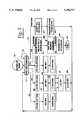
- FIG. 1is a block diagram of a computer system which has a hard disk drive and suspend/resume capability, and which embodies the present invention
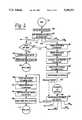
- FIG. 2is a flowchart of pertinent portions of an interrupt service routine executed by a processor which is a component of the system of FIG. 1;
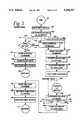
- FIG. 3is a flowchart of pertinent portions of a program executed by a microprocessor in the hard disk drive of FIG. 1;
- FIG. 4is a flowchart of an alternative embodiment of the program represented by the flowchart of FIG. 3;
- FIG. 5 and 6are flow charts respectively similar to FIGS. 2 and 3 but showing another alternative embodiment of the invention.
- a computer system 10includes a central processing unit (CPU) 11, a push-button switch. 12 which is coupled to the CPU 11, a conventional computer keyboard 13, a main memory 16, a hard disk drive 17 and a power supply 18.
- the hard disk drive 17is electrically coupled to the rest of the system 10 through one or more cables, which in the preferred embodiment are conventional and are collectively represented in a diagrammatic form at 19.
- the power supply 18includes a power source 20 which is a rechargeable battery in the preferred embodiment, and which supplies DC power to the CPU 11 at 21, to the main memory 16 at 22, and to the hard disk drive 17 through a selectively actuable electronic power switch 23.
- a power source 20which is a rechargeable battery in the preferred embodiment, and which supplies DC power to the CPU 11 at 21, to the main memory 16 at 22, and to the hard disk drive 17 through a selectively actuable electronic power switch 23.
- the CPU 11includes two separate microprocessors, namely a main processing unit (MPU) 26 and a system control processor (SCP) 27.
- the SCP 27is provided to take some of the processing burden off the MPU 26, and persons of ordinary skill in the art will recognize that the SCP could in fact be omitted and that the MPU 26 could perform all processing functions of the CPU 11.
- the systemoperates faster and more efficiently when both the MPU 26 and SCP 27 are present.
- the MPU 26is, in the preferred embodiment, an Intel 80386 SL microprocessor manufactured by Intel Corporation of Santa Clara, Calif., along with typical associated support circuitry. This particular microprocessor has some special features which will be discussed in more detail later.
- the SCP 27could be implemented with almost any conventional and commercially available microprocessor and its associated support circuits.
- the keyboard 13is entirely conventional, and is coupled through a conventional cable 31 to the SCP 27.
- the SCP 27also receives from the hard disk drive on a line 32 a signal !LED, which will be described in more detail later.
- the exclamation point (!) in front of the signal nameindicates that the signal is active low.
- the SCP 27produces an output signal ENABLE on a line 33, which is coupled to one input of a two-input AND gate 36, the other input of which is coupled to the line 32 from the hard disk drive which carries the signal !LED.
- the SCP 27also outputs a signal INT on a line 37, which is coupled to one input of a two-input OR gate 38, the other input of which is coupled to the output 39 of the AND gate 36.
- the output 41 of the OR gate 38is coupled to the input of a three-state buffer 42, which is always actuated.
- the output 43 from the three-state buffer 42is connected to an interrupt input EXTSMI of the MPU 26.
- the line 32is already present in conventional cables of the type shown diagrammatically at 19, and thus use of this line to create an interrupt according to the present invention avoids the expense and inconvenience of non-standard cabling while ensuring that the cabling and disk drive both remain fully compatible with pre-existing systems.
- An interrupt signal HDINT supplied by the hard disk 17 on a line 46is coupled to a further interrupt input IRQ of the MPU 26.
- the MPU 26produces on an output line 47 a power control signal PWRCTL, which is connected to a control input of the electronic power switch 23.
- PWRCTLWhen the signal PWRCTL is in respective logical states, the electronic power switch 23 respectively permits and prevents the application of DC power to the hard disk drive 17.
- the MPU 26outputs address and control data on respective buses 51 and 52, and sends and receives data on a bidirectional data bus 53.
- the address bus 51, control bus 52 and data bus 53are coupled to the main memory 16 and to the hard disk drive 17.
- the MPU 26also provides refresh control signals 56 for the main memory 16, which in the preferred embodiment is implemented with dynamic random access memory components (DRAM).
- DRAMdynamic random access memory components
- the hard disk drive 17includes a microprocessor 71, which could be almost any conventional and commercially available microprocessor.
- the microprocessor 71generates the previously mentioned !LED signal on line 32 and the HDINT signal on line 46.
- the hard disk drive 17includes an LED 72, which is connected between the line 32 and a source of power. Thus, when the line 32 carries a logic low voltage, the LED 72 will be illuminated, whereas when the line 32 carries a logic high voltage, the LED 72 will not be illuminated.
- the LED 72is used to provide a visual indication of when the hard disk drive 17 is carrying out a command.
- the microprocessor 71generates address and control signals on respective address and control buses 76 and 77, and sends and receives data on a bidirectional data bus 78.
- the data bus 78is connected to inputs of an eight-bit register 81 and an eight-bit register 82, and outputs of these registers are connected through respective three-state buffers 83 and 84 to the system data bus 53.
- the system data bus 53is connected to inputs of an eight-bit register 86 and an eight-bit register 7, and the outputs of these registers are coupled through respective three-state buffers 88 and 89 to the disk data bus 78.
- the register 82includes a DRQ bit 91 and a BSY bit 92, which will be discussed in more detail later.
- the system address and control buses 51 and 52are connected to a decoding circuit 94 of a conventional type.
- the decoding circuit 94has four outputs 96-99, and can selectively actuate one of these outputs in response to respective predetermined combinations of signals on the address bus 51 and control bus 52.
- the output 97enables the three-state buffer 84 so that the contents of register 82 are placed on the system data bus 53.
- the three-state buffer 83is enabled so that the contents of register 81 are placed on the system data bus 53.
- output 99is actuated, the data present on system data bus 53 is loaded into the register 87, and when output 98 is enabled, the data on the system data bus 53 is loaded into the register 86.
- the decode circuit 104has several outputs, including four outputs 106-109.
- the output 106When the output 106 is actuated, it enables the three-state buffer 88 so that the contents of register 86 are placed onto the disk data bus 78.
- the output 107When the output 107 is actuated, it enables the three-state buffer 89 so that the contents of register 87 are placed onto the disk data bus 78.
- the output 108is actuated, the data on disk data bus 78 is loaded into the register 81, and when the output 109 is actuated, the data on disk data bus 78 is loaded into register 82.
- the hard disk drive 17also includes a read only memory (ROM) 112, which is coupled to the address, control and data buses 76-78, and which can be selected by an output 113 from the decode circuit 104.
- the ROM 112contains a program which is executed by the microprocessor 71, along with some data constants which are used by the program.
- the hard disk drive 17further includes a random access memory (RAM) 116, which is coupled to the address, control and data buses 76-78 and to select lines 117 from the decode circuit 104.
- the microprocessor 71can dynamically store data in and retrieve data from the RAM 116 while it is executing the program provided in the ROM 112.
- the data bus 78 and some select lines 122 from the decode circuit 104are connected to a physical drive section 121.
- the physical drive section 121includes conventional and not-illustrated components such as one or more rotating magnetic platters, one or more movable read/write heads each engageable with a platter surface, a mechanism for moving each head relative to its platter, and the electrical support circuitry for each head.
- the CPU 11uses the register 86 to send commands to the disk drive 17, and uses the register 87 to pass data to the disk drive 17.
- the disk drive 17uses the register 81 to pass data to the CPU 11, and maintains in the register 82 certain status information, such as the DRQ bit 91 which is set when the disk drive 17 is carrying out a command and the BSY bit 92 which can be repeatedly set and reset as a command is carried out to provide handshaking information which facilitates a transfer of data between the CPU 11 and disk drive 17.
- the !LED line 32is set to a logic low voltage at the start of a command to turn on the LED 72, and is switched back to a logic high voltage when the command concludes, as described in more detail later.
- the HDINT signalis used during execution of commands to interrupt the application program in the CPU 11, for example to effect the transfer of each of several blocks of data between the CPU 11 and the hard disk drive 17.
- the present inventioninvolves changes to the program stored in the ROM 112 but, aside from this, the hard disk drive 17 is structurally conventional in all respects.
- the main processing unit (MPU) 26has some special features. These features are inherent and integral to the commercially available microprocessor used for the MPU 26, and are not in and of themselves the focus of the present invention. Nevertheless, these special features are briefly described here in order to facilitate a thorough and accurate understanding of the present invention.
- the MPU 26is a protected mode microprocessor.
- the MPU 26When operating in the protected mode, the MPU 26 typically does not have unrestricted control of the system.
- the main memory 16might at some specific point in time include a multi-tasking operating system such as OS/2 or UNIX, a first application program such as a word processor, and a second application program such as a spreadsheet.
- OS/2 or UNIXa multi-tasking operating system
- first application programsuch as a word processor
- a second application programsuch as a spreadsheet.
- the operating systemAs the operating system is turning the MPU 26 over to the second applications program, it places the MPU 26 in a protected mode which prevents the second application program from doing certain things such as changing the internal registers of the MPU which control protected mode or changing the portions of main memory 16 storing the operating system and the first application program.
- the MPU 26has, in addition to a standard interrupt handling structure which can be triggered by an event such as actuation of the IRQ input by a signal on line 46, a special service management interrupt which can be triggered by manual actuation of the push-button switch 12 or by actuation of the EXTSMI input by the signal on line 43.
- a service management interruptUpon the occurrence of a service management interrupt, the internal hardware of the MPU 26 automatically stores in a special reserved management portion 126 of the main memory 16 every facet of the current operational state of the MPU, including all internal registers and flags. The MPU 26 is then automatically placed in a non-protected operational mode, and begins execution of a special service management interrupt handling routine provided in the management portion 126 of the main memory 16.
- the MPU 26is operating in protected mode for a particular application at the point in time when it is interrupted, the entire status of the MPU at the time of the interrupt is saved, including the existence of the protected mode, the special handling routine for the interrupt is then executed in non-protected or "real" mode, and then as control is returned to the interrupted application program the entire stored status of the MPU, including the existence of protected mode, is restored.
- the handling of the interruptis invisible to the application program and does not affect the status of its protected mode, but during the special handling routine the MPU operates in real mode without the limitations of the application program's protected mode, and thus has virtually unrestricted access to the system in order to carry out its pertinent task.
- a further special feature of the MPU 26is that it has a status bit shown diagrammatically at 128 and a special software instruction which, when executed, causes the MPU 26 to enter a suspend state in which it halts and internally shuts off power to almost all of its circuitry, except for a few portions such as the portion which generates the refresh control signals 56.
- the MPU 26automatically turns all of its internal power back on, sets the status bit 128 to indicate that it has been in the suspend state, and then initiates a self-reset which does not affect the status bit 128 but is otherwise similar to the manner in which the MPU 26 responds to a system reset generated externally to itself.
- the software routinecan check the status bit 128 to see whether or not the reset was caused by an exit from the suspend state. It is emphasized again that the special features of the MPU 26 discussed above are inherent and integral to the commercially available microprocessor used for the MPU 26, namely the Intel 80386 SL microprocessor. Therefore, these features have been only briefly described for purposes of convenience.
- FIG. 2is a flowchart showing portions of this interrupt handling routine which embody features of the present invention.
- block 131indicates the occurrence of a service management interrupt, for example due to actuation of the switch 12, due to actuation of the line 43, or due to the occurrence of some other condition.
- the occurrence of this interruptcauses the hardware of the MPU 26 to automatically save the entire current status of the MPU in the management portion 126 of the main memory 16, including all internal registers and status flags.
- thisis performed by the hardware and is technically not a part of the software interrupt handling routine, it is shown in block 132 of FIG. 2 for clarity and in order to facilitate an understanding of the present invention. Control is then transferred to the software interrupt handling routine in the portion 126 of the main memory, beginning with block 133 of FIG. 2.
- the handling routinechecks certain status flags in order to determine the source of the interrupt, or in other words whether it was caused by actuation of the switch 12, actuation of the line 43, or some other event. If it was caused by actuation of the switch 12 or by actuation of the line 43, then control proceeds as respectively shown at 134 or 136, whereas if the cause was some other event control proceeds as shown at 136-139 to respective routines which are not pertinent to the present invention and are thus not illustrated or described.
- controlproceeds at 134 to block 141, where the MPU 26 reads the contents of the status register 82 in the hard disk drive 17 and checks the DRQ bit 91. If the DRQ bit is set, then the hard disk drive 17 is in the middle or carrying out an operation which the interrupted application program initiated before it was interrupted, and thus the MPU 26 must wait until the operation is completed before the MPU can shut down the hard disk drive 17 in order to implement the suspend mode. In this case, the MPU 26 proceeds to block 142, where it directs the SCP 27 to actuate its enable output line 33, which enables the AND gate 36.
- the hard disk drive 17When the hard disk drive 17 completes the operation in progress, it switches the line 32 to a logic high level to turn off the LED 72, as a result of which both inputs of the AND gate 36 will be at a logic high level, and thus the output 39 of the AND gate 36 will be actuated and in turn will actuate one input of the OR gate 38, causing the OR gate 38 to actuate its output 41 and thus the line 43 so that another service management interrupt is generated at the EXTSMI input of the MPU 26. Consequently, the application program will again be interrupted and, at 131 and 132 in FIG. 2, the entire status of the MPU 26 will again be stored in the portion 126 of the main memory 16.
- the MPUwill determine that the interrupt was caused by a change on line 32 which actuated line 43, and will thus proceed at 136 to block 146. It should be noted that, if it had been determined in block 141 that the DRQ bit was not set, or in other words that the hard disk drive 17 was not in the middle of an operation, control would have been transferred at 147 directly from block 141 to block 146. In either case, at block 146 the MPU 26 uses the address, control and data buses 51-53 to load a SUSPEND command into the register 86 of the hard disk drive 17.
- this commandnotifies it that the system 10 will be entering suspend mode, and causes it to formulate in the RAM 116 a 512 byte block of data which contains every facet of its current status, including all registers and flags.
- the MPU 26has proceeded to block 147 in FIG. 2, where it uses the address, control and data buses 51-53 to load a REQUEST command into the register 86. In a manner described in more detail later, this causes the microprocessor 71 to successively send all 512 bytes of the data block it has formulated in the RAM 116 through the register 81 to the MPU 26. Meanwhile, at block 148 in FIG.
- the MPU 26accepts this 512 byte data block, and stores it in a reserved section of the main memory 16. Then, at 149, the MPU 26 deactuates the PWRCTL line 47, so that the electronic power switch 23 is disabled and shuts off all power to the hard disk drive 17. At this point, the MPU could also power down other peripherals present in the system. Then, at 151 in FIG. 2, the MPU 26 executes the software instruction which causes it to enter the suspend mode, in which it halts and internally shuts off power to substantially all portions of its circuitry.
- Manual deactuation of the push-button switch 12is treated differently by the MPU 26 than actuation thereof.
- deactuation of the switch 12produces a service management interrupt
- deactuationdoes not produce another interrupt.
- deactuation of the switch 12causes the MPU 26 to automatically restore internal power to itself, to then set the special internal status bit shown diagrammatically at 128 in FIG. 1, and to then initiate a self-reset which does not affect the status bit 128 but which forces the MPU 26 into real mode and causes the MPU 26 to transfer control at 153 to a block 154.
- Block 154is the start of a software routine which can also be entered at 155 in response to a power-up reset.
- the softwarechecks the status bit 128 and other similar indicators in order to determine the cause of the reset. In the event the status bit 128 is set, block 154 would be exited at 157. If the status bit were not set, control would be transferred as shown diagrammatically at 161-164 to one or more other routines which are not pertinent to the present invention and are thus not illustrated and described.
- the transfer at 157 to block 166represents a branch from the software reset handling routine to the special interrupt handling routine in the portion 126 of main memory 16.
- the MPU 26deactuates the signal PWRCTL on line 47 so that the electronic power switch 23 again supplies power to the hard disk drive 17.
- the MPU 26would also turn on power to other not-illustrated peripherals which may be present, such as a display and/or a floppy disk drive.
- the MPU 26uses the address, control and data buses 51-53 to load a RESTORE command into the register 86 of the hard disk drive 17, to indicate to the hard disk drive 17 that it will be receiving a block of 512 bytes to use in restoring its status.
- the MPU 26retrieves from the main memory 16 the 512 byte data block stored there at block 148 of FIG. 2, and successively transmits these 512 bytes across the data bus 53 and through the register 87 to the microprocessor 71.
- the microprocessor 71restores the status of the hard disk drive 17 from the information in the data block, so that the hard disk drive 17 is now in precisely the state it was in before it lost power.
- the hardware of the MPU 26automatically restores at 169 the complete status of the MPU 26 which has been stored in the management portion 126 of the main memory 16, and of course the interrupted application program is still resident in the main memory 16, along with all other programs which are active.
- the application programresumes executing without any knowledge that the system has been substantially shut down and restarted. The application program continues as if it has never been interrupted in the first place.
- FIG. 3is a flowchart showing portions of the program which is stored in the ROM 112 of FIG. 1 and which is executed by the microprocessor 71 of hard disk drive 17 during the foregoing procedure.
- a power-up reset situationcauses execution to start at 176, and to proceed to 177 where, as shown diagrammatically at 178, the microprocessor 71 waits for the CPU 11 to load a command into the register 86.
- controlproceeds to one of several different routines in dependence on the specific command. In particular, if the command is a SUSPEND command or a RESTORE command, control proceeds as shown respectively at 179 and 181, whereas other commands which are conventional cause control to proceed along respective paths designated at 182, 183 and 184.
- the command corresponding to a transfer at 183 to block 186This might, for example, be a command instructing the hard disk drive 17 to accept a block of data from the CPU 11 and to store this data on the hard disk of the physical drive section 121.
- the microprocessor 71sets the line 32 to a logic low level in order to turn the LED 72 on, the LED providing visual indication that the hard disk drive is carrying out an operation.
- the microprocessor 71loads the status register 82 with a word which has the effect of setting the DRQ bit, so that if the MPU 26 reads the register 82 the DRQ bit will indicate that the hard disk drive 17 is carrying out an operation.
- the microprocessor 71carries out the specific steps necessary to carry out the command.
- the microprocessor 71can toggle the busy bit BSY 92 in the register 82 to provide an indication of when it is ready to accept each byte, and the MPU 26 can monitor the BSY bit and load an additional byte into the register 87 each time the BSY bit is cleared.
- the microprocessor 71initially stores these received bytes in the RAM 116.
- the MPU 26may return to other processing while the microprocessor 71 retrieves these bytes from the RAM 11.6 and stores them on the hard disk in the physical drive section 121. Then, the microprocessor 71 can send an HDINT signal on the line 46 in order to interrupt the MPU 26, causing the MPU 26 to send another portion of the data block which is to be stored. This is all represented diagrammatically in FIG. 3 by the broken line 187.
- microprocessor 71reaches a point at block 188 where it sets the BSY bit 92 in the register 82 for the last time, for example where it has accepted from the MPU 26 the very last byte to be stored. It then proceeds to store this information on the hard disk in the physical drive section 121 and to do any associated final housekeeping, and at some point during this process it clears the DRQ bit 91 in the status register 82, and at block 191 changes the line 32 to a logic high level to the turn the LED 72 off. Thereafter, at 192, the microprocessor 71 clears the BSY bit 92 in the register 82. It is a requirement of the present invention that, at the completion of a command, the LED 72 be turned off before the BSY bit in the register 82 is cleared, for the following reason.
- the MPU 26checks the DRQ bit at block 141 in FIG. 2. If the microprocessor 71 is in the middle of a command, for example at 187 in FIG. 3, the DRQ bit will be set, and thus as described above in association with block 142-144 of FIG. 2, the MPU 26 will enable the line 33 in FIG. 1 and then return control to the application program to wait for the hard disk drive 17 to complete what it is doing. It is important that the application program not be able to instruct the hard disk drive 17 to start a new command.
- the interrupt handling routinewould proceed to block 146 in FIG. 2 where, as described above, the MPU 26 sends the hard disk drive 17 a SUSPEND command.
- thiscauses the microprocessor 71 to proceed at 179 from block 177 to block 193, where it collects every facet of its current status and formulates in the RAM 116 a 512 byte block of data which includes all of this status. The status may take up only a portion of the 512 available bytes, and the remaining bytes can in fact be "garbage".
- the microprocessorwaits for a request command from the MPU 26, as shown diagrammatically at 196. Meanwhile, MPU 26 proceeds from block 146 to block 147 in FIG.
- the microprocessor 71proceeds from block 194 in FIG. 3 to block 197, where it transmits through the register 81 to the MPU 26 the 512 byte block of data it has formulated in the RAM 116. Then, at block 198, the microprocessor 71 halts, and waits for the MPU 26 to use the electronic power switch 23 to shut off power to the hard disk drive 17 in the manner already described above.
- the MPU 26When the MPU 26 eventually exits from the suspend mode, it will use the electronic power switch 23 to turn the power to the hard disk drive 17 back on, as discussed above in association with block 166 in FIG. 2. In FIG. 3, this produces a power-up reset event which forces the microprocessor 71 to block 176 in FIG. 3, following which the microprocessor 71, typically after doing some initialization, proceeds to block 177, where it waits at 178 for a command from the MPU 26. Meanwhile, the MPU 26 proceeds to block 167 in FIG. 2, where it loads the RESTORE command into the register 86 of the hard disk drive 17.
- FIG. 4is a flowchart-showing an alternative embodiment of the program of FIG. 3. Equivalent elements in FIGS. 3 and 4 are designated with identical reference numerals. Only the differences are described in detail below.
- the microprocessor 71proceeds at 179 from block 177 to block 211 of FIG. 4.
- the microprocessorcollects every facet of its status.
- the microprocessor 71waits for the REQUEST command from the MPU 26, as shown diagrammatically at 213.
- the microprocessor 71proceeds to block 214, where it stores the collected status on a reserved portion of the hard disk in its own physical drive section 121. Then, at block 216, it transmits 512 bytes to the MPU 26.
- 512 bytesmay be undefined "garbage" data, and are transmitted only for purposes of compatibility because the MPU 26 expects to receive and store 512 bytes. Then, the microprocessor 71 halts at 217 and waits for its power to be turned off.
- the microprocessor 71receives the RESTORE command from the MPU 26, and proceeds at 181 from block 177 to block 218, where it retrieves the status information which it stored on the hard disk in block 214, and then restores from this stored data at block 219 every facet of the status which the hard disk drive 17 had before its power was turned off. Then, at block 221, it accepts the 512 bytes which the MPU 26 sends, but it simply discards this data because it has no need for it.
- FIGS. 5 and 6are flow charts which are respectively similar to FIGS. 2 and 3 but show another alternative embodiment of the invention. Elements in FIGS. 5 and 6 which are equivalent to elements in FIGS. 2 and 3 are designated with the same reference numerals used in FIGS. 2 and 3. Only the differences are described in detail below.
- receipt of the SUSPEND commandcauses control to proceed at 243 to block 244, where the disk drive enters a mode where it stops accepting further commands other than the REQUEST command. While waiting for the REQUEST command, the drive completes the activity which is already in progress. Then it deactuates its LED line in order to indicate that at some point the activity has been completed, after which the processor sends the REQUEST command. In response to the REQUEST command, the disk drive formulates the 512 byte block at 193, then resumes accepting all commands at block 245, and then at block 197 transmits the 512 byte block to the processor.
Landscapes
- Engineering & Computer Science (AREA)
- Theoretical Computer Science (AREA)
- Physics & Mathematics (AREA)
- General Engineering & Computer Science (AREA)
- General Physics & Mathematics (AREA)
- Software Systems (AREA)
- Computer Security & Cryptography (AREA)
- Quality & Reliability (AREA)
- Power Sources (AREA)
Abstract
Description
Claims (7)
Priority Applications (1)
| Application Number | Priority Date | Filing Date | Title |
|---|---|---|---|
| US08/143,457US5394527A (en) | 1991-05-17 | 1993-10-26 | Method and apparatus facilitating use of a hard disk drive in a computer system having suspend/resume capability |
Applications Claiming Priority (2)
| Application Number | Priority Date | Filing Date | Title |
|---|---|---|---|
| US70302691A | 1991-05-17 | 1991-05-17 | |
| US08/143,457US5394527A (en) | 1991-05-17 | 1993-10-26 | Method and apparatus facilitating use of a hard disk drive in a computer system having suspend/resume capability |
Related Parent Applications (1)
| Application Number | Title | Priority Date | Filing Date |
|---|---|---|---|
| US70302691ADivision | 1991-05-17 | 1991-05-17 |
Publications (1)
| Publication Number | Publication Date |
|---|---|
| US5394527Atrue US5394527A (en) | 1995-02-28 |
Family
ID=24823653
Family Applications (2)
| Application Number | Title | Priority Date | Filing Date |
|---|---|---|---|
| US08/143,457Expired - LifetimeUS5394527A (en) | 1991-05-17 | 1993-10-26 | Method and apparatus facilitating use of a hard disk drive in a computer system having suspend/resume capability |
| US08/437,065Expired - LifetimeUS5974261A (en) | 1991-05-17 | 1995-05-09 | Method and apparatus facilitating use of a hard disk drive in a computer system having suspend/resume capability |
Family Applications After (1)
| Application Number | Title | Priority Date | Filing Date |
|---|---|---|---|
| US08/437,065Expired - LifetimeUS5974261A (en) | 1991-05-17 | 1995-05-09 | Method and apparatus facilitating use of a hard disk drive in a computer system having suspend/resume capability |
Country Status (1)
| Country | Link |
|---|---|
| US (2) | US5394527A (en) |
Cited By (18)
| Publication number | Priority date | Publication date | Assignee | Title |
|---|---|---|---|---|
| US5511204A (en)* | 1994-09-07 | 1996-04-23 | International Business Machines Corporation | Performing system tasks at power-off using system management interrupt |
| US5535415A (en)* | 1990-03-09 | 1996-07-09 | Seiko Epson Corporation | Method for automatically setting the internal and external port configuration of a computer system |
| US5542076A (en)* | 1991-06-14 | 1996-07-30 | Digital Equipment Corporation | Method and apparatus for adaptive interrupt servicing in data processing system |
| US5551033A (en)* | 1991-05-17 | 1996-08-27 | Zenith Data Systems Corporation | Apparatus for maintaining one interrupt mask register in conformity with another in a manner invisible to an executing program |
| US5613163A (en)* | 1994-11-18 | 1997-03-18 | International Business Machines Corporation | Method and system for predefined suspension and resumption control over I/O programs |
| US5649231A (en)* | 1994-01-25 | 1997-07-15 | Fujitsu Limited | Storage control method and apparatus having a buffer storage for transferring variable amounts of data to a main storage based on current system load |
| US5652890A (en)* | 1991-05-17 | 1997-07-29 | Vantus Technologies, Inc. | Interrupt for a protected mode microprocessor which facilitates transparent entry to and exit from suspend mode |
| US5727221A (en)* | 1994-12-22 | 1998-03-10 | Texas Instruments Incorporated | Computer system power management interconnection circuitry and systems |
| US5768617A (en)* | 1991-08-07 | 1998-06-16 | Adaptec, Inc. | Intelligent hardware for automatically reading and writing multiple sectors of data between a computer bus and a disk drive |
| US5845134A (en)* | 1992-10-29 | 1998-12-01 | Kabushiki Kaisha Toshiba | Suspend/resume control method and system |
| US5915119A (en)* | 1996-10-01 | 1999-06-22 | Ncr Corporation | Proxy terminal for network controlling of power managed user terminals in suspend mode |
| US5974008A (en)* | 1997-09-12 | 1999-10-26 | Samsung Electronics Co., Ltd. | Apparatus for controlling disk player of a computer system |
| US6161162A (en)* | 1993-12-08 | 2000-12-12 | Nec Corporation | Multiprocessor system for enabling shared access to a memory |
| US20050170893A1 (en)* | 2002-07-03 | 2005-08-04 | Muir Robert L. | Gaming machine power fail enhancement |
| US20060069930A1 (en)* | 2004-09-30 | 2006-03-30 | Seagate Technology Llc | Bus architecture with reduced power mode during an access time |
| US20070124551A1 (en)* | 2005-11-30 | 2007-05-31 | Dai Taninaka | Storage system and management method thereof |
| US7664902B1 (en)* | 2004-03-16 | 2010-02-16 | Super Talent Electronics, Inc. | Extended SD and microSD hosts and devices with USB-like high performance packetized interface and protocol |
| US10591334B2 (en)* | 2016-02-26 | 2020-03-17 | Micro Motion, Inc. | Limiting a drive signal |
Families Citing this family (1)
| Publication number | Priority date | Publication date | Assignee | Title |
|---|---|---|---|---|
| US8959255B2 (en)* | 2005-10-27 | 2015-02-17 | Hewlett-Packard Development Company, L.P. | Computer protection system and method |
Citations (52)
| Publication number | Priority date | Publication date | Assignee | Title |
|---|---|---|---|---|
| JPS5322345A (en)* | 1976-08-13 | 1978-03-01 | Citizen Watch Co Ltd | Control unit of computer |
| US4294496A (en)* | 1979-08-03 | 1981-10-13 | Gm Research | Portable computer enclosure |
| US4317180A (en)* | 1979-12-26 | 1982-02-23 | Texas Instruments Incorporated | Clocked logic low power standby mode |
| US4381552A (en)* | 1978-12-08 | 1983-04-26 | Motorola Inc. | Stanby mode controller utilizing microprocessor |
| US4458307A (en)* | 1977-09-22 | 1984-07-03 | Burroughs Corporation | Data processor system including data-save controller for protection against loss of volatile memory information during power failure |
| US4461003A (en)* | 1980-06-04 | 1984-07-17 | Nippondenso Co., Ltd. | Circuit arrangement for preventing a microcomputer from malfunctioning |
| US4506323A (en)* | 1982-03-03 | 1985-03-19 | Sperry Corporation | Cache/disk file status indicator with data protection feature |
| US4523295A (en)* | 1982-09-07 | 1985-06-11 | Zenith Electronics Corporation | Power loss compensation for programmable memory control system |
| US4564751A (en)* | 1985-03-26 | 1986-01-14 | The Legacy Group Research And Development Limited Partnership | Wrap-around auxiliary keyboard |
| US4626986A (en)* | 1980-12-29 | 1986-12-02 | Fujitsu Limited | Processor having plural initial loading programs for loading different operating systems |
| US4646307A (en)* | 1983-06-22 | 1987-02-24 | Sharp Kabushiki Kaisha | Memory contents confirmation |
| US4658352A (en)* | 1983-06-02 | 1987-04-14 | Pioneer Electronic Corporation | Computer system with a back-up power supply |
| US4674089A (en)* | 1985-04-16 | 1987-06-16 | Intel Corporation | In-circuit emulator |
| US4689761A (en)* | 1984-08-14 | 1987-08-25 | Metaphor Computer Systems | Multiple independent input peripherals |
| US4694393A (en)* | 1983-06-14 | 1987-09-15 | Sharp Kabushiki Kaisha | Peripheral unit for a microprocessor system |
| US4698748A (en)* | 1983-10-07 | 1987-10-06 | Essex Group, Inc. | Power-conserving control system for turning-off the power and the clocking for data transactions upon certain system inactivity |
| US4734851A (en)* | 1985-04-17 | 1988-03-29 | Dennis Director | Write protect control circuit for computer hard disc systems |
| US4757505A (en)* | 1986-04-30 | 1988-07-12 | Elgar Electronics Corp. | Computer power system |
| US4763333A (en)* | 1986-08-08 | 1988-08-09 | Universal Vectors Corporation | Work-saving system for preventing loss in a computer due to power interruption |
| US4782468A (en)* | 1986-08-05 | 1988-11-01 | Bally Manufacturing Corporation | Line power failure scheme for a gaming device |
| US4823292A (en)* | 1986-08-18 | 1989-04-18 | U.S. Philips Corporation | Data processing apparatus with energy saving clocking device |
| US4839837A (en)* | 1986-06-04 | 1989-06-13 | Chang Bo E | Three layered laptop computer |
| US4868832A (en)* | 1986-04-30 | 1989-09-19 | Marrington S Paul | Computer power system |
| US4870570A (en)* | 1983-01-24 | 1989-09-26 | Sharp Kabushiki Kaisha | Control system for multi-processor |
| US4907150A (en)* | 1986-01-17 | 1990-03-06 | International Business Machines Corporation | Apparatus and method for suspending and resuming software applications on a computer |
| US4933785A (en)* | 1988-03-01 | 1990-06-12 | Prairietek Corporation | Disk drive apparatus using dynamic loading/unloading |
| US4945335A (en)* | 1988-10-06 | 1990-07-31 | Pioneer Electronic Corporation | Electronic unit operable in conjunction with body unit |
| US4980836A (en)* | 1988-10-14 | 1990-12-25 | Compaq Computer Corporation | Apparatus for reducing computer system power consumption |
| US4991129A (en)* | 1989-07-25 | 1991-02-05 | Areal Technology, Inc. | Dual mode actuator for disk drive useful with a portable computer |
| US5014193A (en)* | 1988-10-14 | 1991-05-07 | Compaq Computer Corporation | Dynamically configurable portable computer system |
| US5021983A (en)* | 1989-11-13 | 1991-06-04 | Chips And Technologies, Inc. | Suspend/resume apparatus and method for reducing power consumption in battery powered computers |
| US5027273A (en)* | 1985-04-10 | 1991-06-25 | Microsoft Corporation | Method and operating system for executing programs in a multi-mode microprocessor |
| US5027294A (en)* | 1989-01-27 | 1991-06-25 | Zenith Data Systems Corporation | Method and apparatus for battery-power management using load-compensation monitoring of battery discharge |
| US5068652A (en)* | 1989-06-23 | 1991-11-26 | Kabushiki Kaisha Toshiba | Personal computer having condition indicator |
| US5077551A (en)* | 1988-11-30 | 1991-12-31 | Kabushiki Kaisha Toshiba | Display panel open/closed detection mechanism, and portable electronic apparatus using the same |
| US5083266A (en)* | 1986-12-26 | 1992-01-21 | Kabushiki Kaisha Toshiba | Microcomputer which enters sleep mode for a predetermined period of time on response to an activity of an input/output device |
| US5086387A (en)* | 1986-01-17 | 1992-02-04 | International Business Machines Corporation | Multi-frequency clock generation with low state coincidence upon latching |
| US5129091A (en)* | 1988-05-06 | 1992-07-07 | Toppan Printing Co., Ltd. | Integrated-circuit card with active mode and low power mode |
| US5142684A (en)* | 1989-06-23 | 1992-08-25 | Hand Held Products, Inc. | Power conservation in microprocessor controlled devices |
| US5155840A (en)* | 1990-03-16 | 1992-10-13 | Nec Corporation | Single-chip mircocomputer with clock-signal switching function which can disable a high-speed oscillator to reduce power consumption |
| US5163153A (en)* | 1989-06-12 | 1992-11-10 | Grid Systems Corporation | Low-power, standby mode computer |
| US5167024A (en)* | 1989-09-08 | 1992-11-24 | Apple Computer, Inc. | Power management for a laptop computer with slow and sleep modes |
| US5175853A (en)* | 1990-10-09 | 1992-12-29 | Intel Corporation | Transparent system interrupt |
| US5175845A (en)* | 1988-12-09 | 1992-12-29 | Dallas Semiconductor Corp. | Integrated circuit with watchdog timer and sleep control logic which places IC and watchdog timer into sleep mode |
| US5182810A (en)* | 1989-05-31 | 1993-01-26 | Dallas Semiconductor Corp. | Isolation gates to permit selective power-downs within a closely-coupled multi-chip system |
| US5189647A (en)* | 1991-02-25 | 1993-02-23 | International Business Machines Corp. | Information processing system having power saving control of the processor clock |
| US5214762A (en)* | 1988-11-07 | 1993-05-25 | Compaq Computer Corporation | Disk drive activity indicator |
| US5218704A (en)* | 1989-10-30 | 1993-06-08 | Texas Instruments | Real-time power conservation for portable computers |
| US5230074A (en)* | 1991-01-25 | 1993-07-20 | International Business Machines Corporation | Battery operated computer power management system |
| US5237692A (en)* | 1990-11-09 | 1993-08-17 | Ast Research Inc. | Internal interrupt controller for a peripheral controller |
| US5241680A (en)* | 1989-06-12 | 1993-08-31 | Grid Systems Corporation | Low-power, standby mode computer |
| US5254888A (en)* | 1992-03-27 | 1993-10-19 | Picopower Technology Inc. | Switchable clock circuit for microprocessors to thereby save power |
Family Cites Families (1)
| Publication number | Priority date | Publication date | Assignee | Title |
|---|---|---|---|---|
| US5136694A (en)* | 1989-04-07 | 1992-08-04 | Zenith Data Systems Corporation | Method and apparatus facilitating communication between two keyboards and a single processor |
- 1993
- 1993-10-26USUS08/143,457patent/US5394527A/ennot_activeExpired - Lifetime
- 1995
- 1995-05-09USUS08/437,065patent/US5974261A/ennot_activeExpired - Lifetime
Patent Citations (54)
| Publication number | Priority date | Publication date | Assignee | Title |
|---|---|---|---|---|
| JPS5322345A (en)* | 1976-08-13 | 1978-03-01 | Citizen Watch Co Ltd | Control unit of computer |
| US4458307A (en)* | 1977-09-22 | 1984-07-03 | Burroughs Corporation | Data processor system including data-save controller for protection against loss of volatile memory information during power failure |
| US4381552A (en)* | 1978-12-08 | 1983-04-26 | Motorola Inc. | Stanby mode controller utilizing microprocessor |
| US4294496A (en)* | 1979-08-03 | 1981-10-13 | Gm Research | Portable computer enclosure |
| US4317180A (en)* | 1979-12-26 | 1982-02-23 | Texas Instruments Incorporated | Clocked logic low power standby mode |
| US4461003A (en)* | 1980-06-04 | 1984-07-17 | Nippondenso Co., Ltd. | Circuit arrangement for preventing a microcomputer from malfunctioning |
| US4626986A (en)* | 1980-12-29 | 1986-12-02 | Fujitsu Limited | Processor having plural initial loading programs for loading different operating systems |
| US4506323A (en)* | 1982-03-03 | 1985-03-19 | Sperry Corporation | Cache/disk file status indicator with data protection feature |
| US4523295A (en)* | 1982-09-07 | 1985-06-11 | Zenith Electronics Corporation | Power loss compensation for programmable memory control system |
| US4870570A (en)* | 1983-01-24 | 1989-09-26 | Sharp Kabushiki Kaisha | Control system for multi-processor |
| US4658352A (en)* | 1983-06-02 | 1987-04-14 | Pioneer Electronic Corporation | Computer system with a back-up power supply |
| US4694393A (en)* | 1983-06-14 | 1987-09-15 | Sharp Kabushiki Kaisha | Peripheral unit for a microprocessor system |
| US4646307A (en)* | 1983-06-22 | 1987-02-24 | Sharp Kabushiki Kaisha | Memory contents confirmation |
| US4698748A (en)* | 1983-10-07 | 1987-10-06 | Essex Group, Inc. | Power-conserving control system for turning-off the power and the clocking for data transactions upon certain system inactivity |
| US4689761A (en)* | 1984-08-14 | 1987-08-25 | Metaphor Computer Systems | Multiple independent input peripherals |
| US4564751A (en)* | 1985-03-26 | 1986-01-14 | The Legacy Group Research And Development Limited Partnership | Wrap-around auxiliary keyboard |
| US5027273A (en)* | 1985-04-10 | 1991-06-25 | Microsoft Corporation | Method and operating system for executing programs in a multi-mode microprocessor |
| US4674089A (en)* | 1985-04-16 | 1987-06-16 | Intel Corporation | In-circuit emulator |
| US4734851A (en)* | 1985-04-17 | 1988-03-29 | Dennis Director | Write protect control circuit for computer hard disc systems |
| US4907150A (en)* | 1986-01-17 | 1990-03-06 | International Business Machines Corporation | Apparatus and method for suspending and resuming software applications on a computer |
| US5086387A (en)* | 1986-01-17 | 1992-02-04 | International Business Machines Corporation | Multi-frequency clock generation with low state coincidence upon latching |
| US4868832A (en)* | 1986-04-30 | 1989-09-19 | Marrington S Paul | Computer power system |
| US4757505A (en)* | 1986-04-30 | 1988-07-12 | Elgar Electronics Corp. | Computer power system |
| US4839837A (en)* | 1986-06-04 | 1989-06-13 | Chang Bo E | Three layered laptop computer |
| US4782468A (en)* | 1986-08-05 | 1988-11-01 | Bally Manufacturing Corporation | Line power failure scheme for a gaming device |
| US4763333A (en)* | 1986-08-08 | 1988-08-09 | Universal Vectors Corporation | Work-saving system for preventing loss in a computer due to power interruption |
| US4763333B1 (en)* | 1986-08-08 | 1990-09-04 | Univ Vectors Corp | |
| US4823292A (en)* | 1986-08-18 | 1989-04-18 | U.S. Philips Corporation | Data processing apparatus with energy saving clocking device |
| US5083266A (en)* | 1986-12-26 | 1992-01-21 | Kabushiki Kaisha Toshiba | Microcomputer which enters sleep mode for a predetermined period of time on response to an activity of an input/output device |
| US4933785A (en)* | 1988-03-01 | 1990-06-12 | Prairietek Corporation | Disk drive apparatus using dynamic loading/unloading |
| US5129091A (en)* | 1988-05-06 | 1992-07-07 | Toppan Printing Co., Ltd. | Integrated-circuit card with active mode and low power mode |
| US4945335A (en)* | 1988-10-06 | 1990-07-31 | Pioneer Electronic Corporation | Electronic unit operable in conjunction with body unit |
| US5014193A (en)* | 1988-10-14 | 1991-05-07 | Compaq Computer Corporation | Dynamically configurable portable computer system |
| US4980836A (en)* | 1988-10-14 | 1990-12-25 | Compaq Computer Corporation | Apparatus for reducing computer system power consumption |
| US5214762A (en)* | 1988-11-07 | 1993-05-25 | Compaq Computer Corporation | Disk drive activity indicator |
| US5077551A (en)* | 1988-11-30 | 1991-12-31 | Kabushiki Kaisha Toshiba | Display panel open/closed detection mechanism, and portable electronic apparatus using the same |
| US5175845A (en)* | 1988-12-09 | 1992-12-29 | Dallas Semiconductor Corp. | Integrated circuit with watchdog timer and sleep control logic which places IC and watchdog timer into sleep mode |
| US5027294A (en)* | 1989-01-27 | 1991-06-25 | Zenith Data Systems Corporation | Method and apparatus for battery-power management using load-compensation monitoring of battery discharge |
| US5182810A (en)* | 1989-05-31 | 1993-01-26 | Dallas Semiconductor Corp. | Isolation gates to permit selective power-downs within a closely-coupled multi-chip system |
| US5163153A (en)* | 1989-06-12 | 1992-11-10 | Grid Systems Corporation | Low-power, standby mode computer |
| US5241680A (en)* | 1989-06-12 | 1993-08-31 | Grid Systems Corporation | Low-power, standby mode computer |
| US5068652A (en)* | 1989-06-23 | 1991-11-26 | Kabushiki Kaisha Toshiba | Personal computer having condition indicator |
| US5142684A (en)* | 1989-06-23 | 1992-08-25 | Hand Held Products, Inc. | Power conservation in microprocessor controlled devices |
| US4991129A (en)* | 1989-07-25 | 1991-02-05 | Areal Technology, Inc. | Dual mode actuator for disk drive useful with a portable computer |
| US5167024A (en)* | 1989-09-08 | 1992-11-24 | Apple Computer, Inc. | Power management for a laptop computer with slow and sleep modes |
| US5218704A (en)* | 1989-10-30 | 1993-06-08 | Texas Instruments | Real-time power conservation for portable computers |
| US5021983A (en)* | 1989-11-13 | 1991-06-04 | Chips And Technologies, Inc. | Suspend/resume apparatus and method for reducing power consumption in battery powered computers |
| US5021983B1 (en)* | 1989-11-13 | 1996-05-28 | Chips & Technologies Inc | Suspend/resume apparatus and method for reducing power consumption in battery powered computers |
| US5155840A (en)* | 1990-03-16 | 1992-10-13 | Nec Corporation | Single-chip mircocomputer with clock-signal switching function which can disable a high-speed oscillator to reduce power consumption |
| US5175853A (en)* | 1990-10-09 | 1992-12-29 | Intel Corporation | Transparent system interrupt |
| US5237692A (en)* | 1990-11-09 | 1993-08-17 | Ast Research Inc. | Internal interrupt controller for a peripheral controller |
| US5230074A (en)* | 1991-01-25 | 1993-07-20 | International Business Machines Corporation | Battery operated computer power management system |
| US5189647A (en)* | 1991-02-25 | 1993-02-23 | International Business Machines Corp. | Information processing system having power saving control of the processor clock |
| US5254888A (en)* | 1992-03-27 | 1993-10-19 | Picopower Technology Inc. | Switchable clock circuit for microprocessors to thereby save power |
Non-Patent Citations (8)
| Title |
|---|
| Clements, Alan; "Microprocessor Systems Design", 1987, Title pages and pp. 117, 246, 353, 354, PWS-Kent Publishing Company, Boston. |
| Clements, Alan; Microprocessor Systems Design , 1987, Title pages and pp. 117, 246, 353, 354, PWS Kent Publishing Company, Boston.* |
| IBM System/360 Principles of Operation, Eighth Edition (Sep., 1968) Title Pages and pp. 68 83.* |
| IBM System/360 Principles of Operation, Eighth Edition (Sep., 1968) Title Pages and pp. 68-83. |
| Microsoft, MS DOS, User s Guide, 1986, Title Pages and p. 245.* |
| Microsoft, MS-DOS, User's Guide, 1986, Title Pages and p. 245. |
| Toshiba T1600 "User's Manual" 2d ed.; Title page, pp. 2-1 to 2-3, and pp. 2-8 to 2-11; 1987. |
| Toshiba T1600 User s Manual 2d ed.; Title page, pp. 2 1 to 2 3, and pp. 2 8 to 2 11; 1987.* |
Cited By (27)
| Publication number | Priority date | Publication date | Assignee | Title |
|---|---|---|---|---|
| US5535415A (en)* | 1990-03-09 | 1996-07-09 | Seiko Epson Corporation | Method for automatically setting the internal and external port configuration of a computer system |
| US5903766A (en)* | 1991-05-17 | 1999-05-11 | Packard Bell Nec, Inc. | Suspend/resume capability for a protected mode microprocessor |
| US5551033A (en)* | 1991-05-17 | 1996-08-27 | Zenith Data Systems Corporation | Apparatus for maintaining one interrupt mask register in conformity with another in a manner invisible to an executing program |
| US5652890A (en)* | 1991-05-17 | 1997-07-29 | Vantus Technologies, Inc. | Interrupt for a protected mode microprocessor which facilitates transparent entry to and exit from suspend mode |
| US6378068B1 (en) | 1991-05-17 | 2002-04-23 | Nec Corporation | Suspend/resume capability for a protected mode microprocesser |
| US5765004A (en)* | 1991-05-17 | 1998-06-09 | Vantus Technologies, Inc. | Suspend/resume capability for a protected mode microprocessor |
| US6301673B1 (en)* | 1991-05-17 | 2001-10-09 | Nec Corporation | Suspend/resume capability for a protected mode microprocessor |
| US5542076A (en)* | 1991-06-14 | 1996-07-30 | Digital Equipment Corporation | Method and apparatus for adaptive interrupt servicing in data processing system |
| US5768617A (en)* | 1991-08-07 | 1998-06-16 | Adaptec, Inc. | Intelligent hardware for automatically reading and writing multiple sectors of data between a computer bus and a disk drive |
| US5845134A (en)* | 1992-10-29 | 1998-12-01 | Kabushiki Kaisha Toshiba | Suspend/resume control method and system |
| US6161162A (en)* | 1993-12-08 | 2000-12-12 | Nec Corporation | Multiprocessor system for enabling shared access to a memory |
| US5649231A (en)* | 1994-01-25 | 1997-07-15 | Fujitsu Limited | Storage control method and apparatus having a buffer storage for transferring variable amounts of data to a main storage based on current system load |
| US5511204A (en)* | 1994-09-07 | 1996-04-23 | International Business Machines Corporation | Performing system tasks at power-off using system management interrupt |
| US5613163A (en)* | 1994-11-18 | 1997-03-18 | International Business Machines Corporation | Method and system for predefined suspension and resumption control over I/O programs |
| US5864702A (en)* | 1994-12-22 | 1999-01-26 | Texas Instruments Incorporated | Computer system power management interconnection circuitry, systems and methods |
| US5727221A (en)* | 1994-12-22 | 1998-03-10 | Texas Instruments Incorporated | Computer system power management interconnection circuitry and systems |
| US5915119A (en)* | 1996-10-01 | 1999-06-22 | Ncr Corporation | Proxy terminal for network controlling of power managed user terminals in suspend mode |
| US5974008A (en)* | 1997-09-12 | 1999-10-26 | Samsung Electronics Co., Ltd. | Apparatus for controlling disk player of a computer system |
| US8241109B2 (en)* | 2002-07-03 | 2012-08-14 | Aristocrat Technologies Australia Pty Limited | Gaming machine power fail enhancement |
| US20050170893A1 (en)* | 2002-07-03 | 2005-08-04 | Muir Robert L. | Gaming machine power fail enhancement |
| US8657669B2 (en) | 2002-07-03 | 2014-02-25 | Aristocrat Technologies Australia Pty Limited | Gaming machine power fail enhancement |
| US20100093427A1 (en)* | 2002-07-03 | 2010-04-15 | Aristocrat Technologies Australia Pty Limited | Gaming machine power fail enhancement |
| US7664902B1 (en)* | 2004-03-16 | 2010-02-16 | Super Talent Electronics, Inc. | Extended SD and microSD hosts and devices with USB-like high performance packetized interface and protocol |
| US20060069930A1 (en)* | 2004-09-30 | 2006-03-30 | Seagate Technology Llc | Bus architecture with reduced power mode during an access time |
| US7716440B2 (en)* | 2005-11-30 | 2010-05-11 | Hitachi, Ltd. | Storage system and management method thereof |
| US20070124551A1 (en)* | 2005-11-30 | 2007-05-31 | Dai Taninaka | Storage system and management method thereof |
| US10591334B2 (en)* | 2016-02-26 | 2020-03-17 | Micro Motion, Inc. | Limiting a drive signal |
Also Published As
| Publication number | Publication date |
|---|---|
| US5974261A (en) | 1999-10-26 |
Similar Documents
| Publication | Publication Date | Title |
|---|---|---|
| US5394527A (en) | Method and apparatus facilitating use of a hard disk drive in a computer system having suspend/resume capability | |
| KR960002543B1 (en) | Peripheral Equipment Control | |
| US6854064B2 (en) | ACPI complaint computer system and overtemperature protection method therefor | |
| US6125449A (en) | Controlling power states of a computer | |
| US6158000A (en) | Shared memory initialization method for system having multiple processor capability | |
| US5802269A (en) | Method and apparatus for power management of distributed direct memory access (DDMA) devices | |
| US5751950A (en) | Secure power supply for protecting the shutdown of a computer system | |
| US5675364A (en) | Display wakeup control | |
| US20020095609A1 (en) | Multiprocessor apparatus | |
| US6035355A (en) | PCI system and adapter requirements following reset | |
| US6832311B2 (en) | Information processing system and resume processing method used in the system | |
| US8756448B2 (en) | Computer system and control method thereof | |
| KR100480415B1 (en) | How to check CD-ROM drive's operation status | |
| EP0584257B1 (en) | Power management capability for a microprocessor having backward compatibility | |
| US6493782B1 (en) | Method for performing hot docking of a portable computer into a docking station | |
| US7200694B2 (en) | Servicing multiple hot-plug events utilizing a common event signal in providing hot-plug attention button support | |
| US5937200A (en) | Using firmware to enhance the functionality of a controller | |
| JPH07152584A (en) | Computer system and interruption controller | |
| JPH08339246A (en) | System and method for computer with sorm session | |
| KR950033777A (en) | Method and apparatus for reducing power consumption in a computer system | |
| JPH096459A (en) | System and method for computer with multilevel postponement timer | |
| US6895517B2 (en) | Method of synchronizing operation frequencies of CPU and system RAM in power management process | |
| EP0283581B1 (en) | Computer system with mode conversion of computer commands | |
| US6625739B1 (en) | Hard power shutdown of a computer by actuating both a keyboard controller independent key and a soft power switch together to bypass the power switch together to bypass the power controller | |
| US6105140A (en) | Secure power supply |
Legal Events
| Date | Code | Title | Description |
|---|---|---|---|
| STCF | Information on status: patent grant | Free format text:PATENTED CASE | |
| AS | Assignment | Owner name:VANTUS TECHNOLOGIES, INC., ILLINOIS Free format text:ASSIGNMENT OF ASSIGNORS INTEREST;ASSIGNOR:ZENITH DATA SYSTEMS CORPORATIO;REEL/FRAME:007453/0477 Effective date:19950424 | |
| AS | Assignment | Owner name:SUMITOMO BANK OF NEW YORK TRUST COMPANY, NEW YORK Free format text:ASSIGNMENT OF ASSIGNORS INTEREST;ASSIGNOR:VANTUS TECHNOLOGIES, INC.;REEL/FRAME:008442/0095 Effective date:19970325 | |
| FEPP | Fee payment procedure | Free format text:PAYOR NUMBER ASSIGNED (ORIGINAL EVENT CODE: ASPN); ENTITY STATUS OF PATENT OWNER: LARGE ENTITY | |
| FPAY | Fee payment | Year of fee payment:4 | |
| AS | Assignment | Owner name:SUMITOMO BANK, LIMITED, NEW YORK BRANCH, THE, AS C Free format text:TRANSFER OF SECURITY INTEREST;ASSIGNOR:SUMITOMO BANK OF NEW YORK TRUST COMPANY;REEL/FRAME:009756/0202 Effective date:19990108 | |
| AS | Assignment | Owner name:VANTUS TECHNOLOGIES, INC., ILLINOIS Free format text:TERMINATION OF SECURITY INTEREST;ASSIGNOR:SUMITOMO BANK LIMITED, THE;REEL/FRAME:010263/0070 Effective date:19990301 | |
| AS | Assignment | Owner name:NEC CORPORATION, JAPAN Free format text:ASSIGNMENT OF ASSIGNORS INTEREST;ASSIGNOR:VANTUS TECHNOLOGIES, INC.;REEL/FRAME:011007/0792 Effective date:20000223 | |
| FEPP | Fee payment procedure | Free format text:PAYOR NUMBER ASSIGNED (ORIGINAL EVENT CODE: ASPN); ENTITY STATUS OF PATENT OWNER: LARGE ENTITY Free format text:PAYER NUMBER DE-ASSIGNED (ORIGINAL EVENT CODE: RMPN); ENTITY STATUS OF PATENT OWNER: LARGE ENTITY | |
| REMI | Maintenance fee reminder mailed | ||
| FPAY | Fee payment | Year of fee payment:8 | |
| SULP | Surcharge for late payment | Year of fee payment:7 | |
| FPAY | Fee payment | Year of fee payment:12 | |
| AS | Assignment | Owner name:VANTUS TECHNOLOGIES, INC., ILLINOIS Free format text:ASSIGNMENT OF ASSIGNORS INTEREST;ASSIGNOR:ZENITH DATA SYSTEMS CORPORATION;REEL/FRAME:027691/0083 Effective date:19950424 |