US5394089A - Battery monitor which indicates remaining capacity by continuously monitoring instantaneous power consumption relative to expected hyperbolic discharge rates - Google Patents
Battery monitor which indicates remaining capacity by continuously monitoring instantaneous power consumption relative to expected hyperbolic discharge ratesDownload PDFInfo
- Publication number
- US5394089A US5394089AUS08/150,278US15027893AUS5394089AUS 5394089 AUS5394089 AUS 5394089AUS 15027893 AUS15027893 AUS 15027893AUS 5394089 AUS5394089 AUS 5394089A
- Authority
- US
- United States
- Prior art keywords
- battery
- instantaneous
- current
- arithmetic unit
- level
- Prior art date
- Legal status (The legal status is an assumption and is not a legal conclusion. Google has not performed a legal analysis and makes no representation as to the accuracy of the status listed.)
- Expired - Lifetime
Links
Images

Classifications
- G—PHYSICS
- G01—MEASURING; TESTING
- G01R—MEASURING ELECTRIC VARIABLES; MEASURING MAGNETIC VARIABLES
- G01R31/00—Arrangements for testing electric properties; Arrangements for locating electric faults; Arrangements for electrical testing characterised by what is being tested not provided for elsewhere
- G01R31/36—Arrangements for testing, measuring or monitoring the electrical condition of accumulators or electric batteries, e.g. capacity or state of charge [SoC]
- G01R31/3644—Constructional arrangements
- G01R31/3648—Constructional arrangements comprising digital calculation means, e.g. for performing an algorithm
- G—PHYSICS
- G01—MEASURING; TESTING
- G01R—MEASURING ELECTRIC VARIABLES; MEASURING MAGNETIC VARIABLES
- G01R31/00—Arrangements for testing electric properties; Arrangements for locating electric faults; Arrangements for electrical testing characterised by what is being tested not provided for elsewhere
- G01R31/36—Arrangements for testing, measuring or monitoring the electrical condition of accumulators or electric batteries, e.g. capacity or state of charge [SoC]
- G01R31/382—Arrangements for monitoring battery or accumulator variables, e.g. SoC
- G01R31/3842—Arrangements for monitoring battery or accumulator variables, e.g. SoC combining voltage and current measurements
- G—PHYSICS
- G01—MEASURING; TESTING
- G01R—MEASURING ELECTRIC VARIABLES; MEASURING MAGNETIC VARIABLES
- G01R31/00—Arrangements for testing electric properties; Arrangements for locating electric faults; Arrangements for electrical testing characterised by what is being tested not provided for elsewhere
- G01R31/36—Arrangements for testing, measuring or monitoring the electrical condition of accumulators or electric batteries, e.g. capacity or state of charge [SoC]
- G01R31/374—Arrangements for testing, measuring or monitoring the electrical condition of accumulators or electric batteries, e.g. capacity or state of charge [SoC] with means for correcting the measurement for temperature or ageing
- Y—GENERAL TAGGING OF NEW TECHNOLOGICAL DEVELOPMENTS; GENERAL TAGGING OF CROSS-SECTIONAL TECHNOLOGIES SPANNING OVER SEVERAL SECTIONS OF THE IPC; TECHNICAL SUBJECTS COVERED BY FORMER USPC CROSS-REFERENCE ART COLLECTIONS [XRACs] AND DIGESTS
- Y10—TECHNICAL SUBJECTS COVERED BY FORMER USPC
- Y10S—TECHNICAL SUBJECTS COVERED BY FORMER USPC CROSS-REFERENCE ART COLLECTIONS [XRACs] AND DIGESTS
- Y10S320/00—Electricity: battery or capacitor charging or discharging
- Y10S320/18—Indicator or display
- Y10S320/21—State of charge of battery
Definitions
- This inventionrelates to a battery monitoring system.
- a battery monitoring systemcomprises,
- fourth meansfor determining a final battery voltage level at which the capacity of the battery is exhausted
- sixth meansfor calculating according to a first predetermined algorithm the total discharge duration of the battery according to the outputs of the fourth and fifth means;
- seventh meansfor calculating according to a second predetermined algorithm the accumulated discharge duration according to the output of the first and second means;
- eighth meansfor assessing the remaining discharge duration available from the battery from the outputs of the sixth and seventh means
- said first predetermined algorithmcomprises a hyperbolic equation having first co-efficients selected from a stored table of such first co-efficients by the output of the fourth means
- said second predetermined algorithmcomprises a cubic equation having second co-efficients selected from a stored table of such second co-efficients by the output of said first means
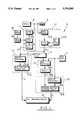
- FIG. 1schematically illustrates a battery monitoring system according to the present invention
- FIG. 2illustrates two typical discharge curves, the upper set of curves illustrating a discharge rate of 15.5% of a 10 hour battery capacity, and the lower set of curves illustrating an 18% discharge rate, the solid lines reflecting data issued by the battery manufacturer and the broken lines reflecting evaluations using the cubic equation of box 17 of FIG. 1.
- a battery monitoring system 10 in accordance with the present inventionis illustrated in FIG. 1 and monitors the condition of battery 9 which is connected to supply a load 8.
- System 10comprises a first evaluating arrangement 11 for evaluating the level of instantaneous current drawn from the battery 9, and a second evaluating arrangement 12 for evaluating the level of instantaneous battery voltage.
- the outputs of arrangements 11 and 12are fed to a third arrangement 13 which computes the level of instantaneous power delivered by the battery.
- a fourth arrangement 14, in this embodiment containing a preset valuedetermines a final voltage level for the battery 9 when the capacity of the battery is exhausted and the outputs of arrangements 13 and 14 are delivered to a fifth arrangement 15 which evaluates the estimated final battery current.
- the output of arrangement 15, together with the output of arrangement 14,is delivered to a sixth arrangement 16 for calculating according to a first predetermined algorithm (as will be explained) the total discharge duration of the battery 9.
- the outputs of the first and second arrangements 11, 12, in addition to being fed to the third arrangement 13are fed to a seventh arrangement 17 which is arranged to evaluate according to a second predetermined algorithm (as will be explained) the accumulated discharge duration and the outputs of the sixth and seventh arrangements 16, 17, are fed to an eighth arrangement 18 which evaluates the remaining discharge duration available from the battery 9.
- the algorithms which are used in the system 10are formulated on the basis of the output from first arrangement 11 being in a normalised form, in part this simply being a percentage of the ten hour discharge rate but in part being modified by variations in temperature of the battery 9 with respect to a predetermined temperature (usually 15° C.). Accordingly, a temperature sensor 21 is provided for sensing battery temperature and the output of sensor 21 operates an arrangement 22 to establish a temperature correction factor which is fed to the first arrangement 11.
- the arrangement 11therefore comprises a current sensor 11A, a temperature normalising unit 11B and a scaling unit 11C.
- the second arrangement 12comprises a voltage sensor 12A, a stored value, 12B reflecting the number of individual cells within the specific battery 9 and an arithmetic unit 12C which provides the output for arrangement 12 so that the output is measured volts per cell.
- the third arrangement 13evaluates the level of instantaneous power delivered by the battery by multiplication of the values delivered to it by the first and second arrangements 11, 12.
- the fourth arrangement 14is provided in this example in a present manner, with the final voltage level of each cell and the fifth arrangement 15 contains a calculating unit 15A which by division of the power value delivered to it by arrangement 13 and the voltage measure delivered by arrangement 14 evaluates the final current and this is scaled by unit 15B to the ten hour discharge rate.
- the sixth arrangement 16comprises an arrangement 16A which stores a first set of co-efficients and which is arranged to output a single set of such co-efficients to unit 16B according to the voltage value provided to unit 16A by arrangement 14.
- Unit 16Bis a calculation unit which evaluates a hyperbolic equation having specified co-efficients as delivered by unit 16A and a specified variable as delivered by unit 15B. The evaluation of this hyperbolic equation establishes a total duration of battery discharge.
- the seventh arrangement 17comprises a unit 17A which stores a table of second co-efficients and according to the value of scaled current delivered to it by unit 11C provides a specific set of such second co-efficients to a calculating unit 17B which is arranged to evaluate the accumulated discharge time from a predetermined cubic equation relating instantaneous voltage with accumulated discharge time.
- the eighth unit 18is arranged to subtract the values delivered to it by units 16 and 17 to thereby provide a measure of the remaining time to final discharge of the battery 9.
- Arrangement 18may also express the remaining discharge time available as a percentage of the total discharge time or may express the accumulated discharge time as a percentage of the total discharge time.
- the cubic equation evaluated by unit 17Bis derived from graphical data provided by battery manufacturers expressing the relationship between measured battery voltage and accumulated discharge time for a particular level of instantaneous current. It has been found that the divergence between the graphical data and the cubic equation is minimal as illustrated by FIG. 2 and by storing sets of co-efficients in unit 18A for particular values of current a substantial reduction of storage space is achieved together with an increased ability to interpolate for unstored sets of co-efficients.
- the hyperbolic equation evaluated by unit 16Bis derived from graphical data provided by battery manufacturers expressing the total discharge period to a particular value of final battery voltage for a series of specific values of instantaneous battery voltage and the divergence between the hyperbolic equation and the graphical data is negligible. Interpolation of unstored co-efficients for the hyperbolic equation is readily effected by unit 16A.
- Sensor 11Ameasures the present current (i in ) flowing through the battery leads as +146 amps, the positive sign indicating that the battery is being discharged.
- Unit 11Bnormalises i in to rated temperature (15° C.) and because the measured temperature in the battery room is 20° C. the temperature correction factor provided by unit 22 is:
- Unit 11Ccalculates current i p in terms of the 10 hour capacity of the battery, to give a percentage, so that the output of arrangement 11 is:
- Unit 12Bdivides the battery voltage by the number of cells (164) to give cell voltage:
- Unit 15Acalculates final current
- (v fis the preset final voltage, i.e. 1.79 established in arrangement 14).
- unit 15Bis scaled by unit 15B to be 18.64% of the 10 hour capacity.
- hyperbolic co-efficients (a,b,c)are stored in unit 16A for specified final voltage values; e.g.
- Unit 17calculates the accumulated discharge time t from a cubic equation of the form
- cubic co-efficients (a,b,c,d)are stored in unit 17A for specified levels of current i p , e.g.
- Arrangement 18evaluates the remaining time as the difference between final time and present time ##EQU1## so that if the discharge continues at the present rate the battery will last for a further 146 minutes.
- arrangement 18may evaluate the percent discharge remaining as ##EQU2## so that the battery has 47.5% of its charge remaining.
- unit 17Ais adapted to interpolate between the nearest stored identifiers and their stored co-efficients to obtain the required identifier and required co-efficients.
- Interpolationmay be carried out on a similar basis by unit 16A in the case where the final voltage V f is not a preset value as dictated by the battery manufacturers which is normally a value specifically contained as an identifier in store unit 16A.
- the systemoutputs on a continuous (very rapid sampling) basis the prediction of the battery capacity remaining at any point in time and this prediction can, if so desired, be used to set or operate alarm devices guarding the battery and load arrangement.
- the system 10may be modified to incorporate a self-learning regime by comparing the projected discharge of the battery 9 with the actual discharge by means of which the system 10 self-adjusts for inefficiencies of the battery and load arrangement and for battery ageing. This is achieved using "electrically erasable programmable read only memory” (EEPROM). Each time a discharge takes place, the system 10 records all the vital parameters and then integrates them with previously stored derived measurements.
- EEPROMelectrically erasable programmable read only memory
- the charging efficiencycan be expressed as: ##EQU4## The result from each charge/discharge cycle is integrated into a continuous store, the "historical charge efficiency”. The system therefore “learns" the charging efficiency of the battery, load and charging unit.
- the recharge timethen can be expressed as: ##EQU5## where BC is the Battery Capacity expressed in Ampere/minutes. All the above variables are stored in electrically erasable programmable read only memory (EEPROM).
- EEPROMelectrically erasable programmable read only memory
Landscapes
- General Physics & Mathematics (AREA)
- Physics & Mathematics (AREA)
- Secondary Cells (AREA)
- Charge And Discharge Circuits For Batteries Or The Like (AREA)
- Remote Monitoring And Control Of Power-Distribution Networks (AREA)
- Tests Of Electric Status Of Batteries (AREA)
- Selective Calling Equipment (AREA)
- Fixing For Electrophotography (AREA)
- Emergency Alarm Devices (AREA)
- Burglar Alarm Systems (AREA)
- Input Circuits Of Receivers And Coupling Of Receivers And Audio Equipment (AREA)
- General Preparation And Processing Of Foods (AREA)
- Meat, Egg Or Seafood Products (AREA)
- Cosmetics (AREA)
Abstract
Description
______________________________________ Ampere hour rate 800 = 10 hour capacity No. of cells 164Temperature correction factor 1% per °C. Ratedtemperature 15° C. Final voltage 294 Final volt/cell 1.79 ______________________________________
______________________________________ Current 146 Amperes Voltage 314.8 Volts Temperature 20° C. ______________________________________
tempco=1+(20-15)×(1/100)=1.05
i.sub.p =(139.05×100)÷800=17.38%
v.sub.in =314.8/164=1.9195
Power=v.sub.in ×i.sub.p =1.9195×139.05=266.90 watts
i.sub.f =power/v.sub.f
i.sub.f =266.90/1.79=149.11 amps
T=a+bi.sup.-1 +ci.sub.f.sup.-2
______________________________________ Final volts a b c ______________________________________ 1.85 -111.738 6662.29 3942.7 1.83 -95.1394 6645.34 5171.71 1.81 -87.7079 6939.18 3580.98 1.79 -74.9541 6913.18 3857.27 1.77 -65.1906 6880.4 4634.92 1.75 -56.4163 6826.9 5202.11 ______________________________________
______________________________________ 1.79 -74.9541 6913.18 3857.27 ______________________________________
______________________________________ T = -74.9541 + (6913 / 18.64) + (3857.27 / (18.64).sup.2 = 307.06 ______________________________________
V=a+bt+ct.sup.2 +dt.sup.3
TABLE I ______________________________________ .sup.i p a b c d ______________________________________ 172 1.655 -4.392 E-3 5.426 E-4 -2.127 E-4 142 1.710 -5.985 E-3 -4.174 E-4 2.164 E-5 106 1.776 -4.722 E-3 2.348 E-5 -2.609 E-6 88 1.804 -2.839 E-3 -1.082 E-5 -7.787 E-7 71 1.837 -1.240 E-3 -2.965 E-5 -1.203 E-7 60 1.852 -7.024 E-2 -3.478 E-2 6.180 E-3 36.9 1.913 -4.214 E-2 -4.087 E-3 3.903 E-3 27 1.940 -3.234 E-2 5.836 E-3 -3.533 E-3 21.6 1.951 -1.648 E-2 6.957 E-4 -1.331 E-3 18 1.964 -1.382 E-2 5.565 E-5 -5.936 E-4 17.38 1.96496 -1.432 E-2 5.77 E-4 -5.8 E-4 15.5 1.968 -1.592 E-2 2.232 E-3 -5.632 E-4 13.6 1.972 -1.361 E-2 2.811 E-3 -5.399 E-4 12.1 1.977 -1.277 E-2 2.092 E-3 -3.312 E-4 11 1.982 -1.310 E-2 2.065 E-3 -2.759 E-4 10 1.986 -9.299 E-3 1.381 E-3 -1.860 E-4 ______________________________________
V=a+b·t+c·t.sup.2 +d·t.sup.3
V=cell voltage=1.9195
a=calculated coefficient=1.96496
b=calculated coefficient=-0.01432
c=calculated coefficient=0.000577
d=calculated coefficient=-0.00058
Charge Rate (CR) Expressed in Ampere/minutes
Depth of Discharge (DD) as % Fully Charged energy level
Claims (3)
T=a+b(i.sub.f).sup.-1 +c(i.sub.f).sup.-2
V=A+Bt+Ct.sup.2 +Dt.sup.3
Priority Applications (1)
| Application Number | Priority Date | Filing Date | Title |
|---|---|---|---|
| US08/150,278US5394089A (en) | 1988-07-21 | 1989-11-29 | Battery monitor which indicates remaining capacity by continuously monitoring instantaneous power consumption relative to expected hyperbolic discharge rates |
Applications Claiming Priority (4)
| Application Number | Priority Date | Filing Date | Title |
|---|---|---|---|
| GB888817364AGB8817364D0 (en) | 1988-07-21 | 1988-07-21 | Battery monitoring system |
| US08/150,278US5394089A (en) | 1988-07-21 | 1989-11-29 | Battery monitor which indicates remaining capacity by continuously monitoring instantaneous power consumption relative to expected hyperbolic discharge rates |
| PCT/GB1989/001428WO1991008494A1 (en) | 1988-07-21 | 1989-11-29 | Battery monitoring system |
| US85219392A | 1992-05-29 | 1992-05-29 |
Related Parent Applications (1)
| Application Number | Title | Priority Date | Filing Date |
|---|---|---|---|
| US85219392AContinuation | 1988-07-21 | 1992-05-29 |
Publications (1)
| Publication Number | Publication Date |
|---|---|
| US5394089Atrue US5394089A (en) | 1995-02-28 |
Family
ID=10640852
Family Applications (1)
| Application Number | Title | Priority Date | Filing Date |
|---|---|---|---|
| US08/150,278Expired - LifetimeUS5394089A (en) | 1988-07-21 | 1989-11-29 | Battery monitor which indicates remaining capacity by continuously monitoring instantaneous power consumption relative to expected hyperbolic discharge rates |
Country Status (10)
| Country | Link |
|---|---|
| US (1) | US5394089A (en) |
| EP (1) | EP0501952B1 (en) |
| JP (1) | JP3125100B2 (en) |
| AT (1) | ATE144330T1 (en) |
| DE (1) | DE68927351D1 (en) |
| DK (1) | DK69292D0 (en) |
| FI (1) | FI922429A0 (en) |
| GB (2) | GB8817364D0 (en) |
| NO (1) | NO922122D0 (en) |
| WO (1) | WO1991008494A1 (en) |
Cited By (55)
| Publication number | Priority date | Publication date | Assignee | Title |
|---|---|---|---|---|
| US5479085A (en)* | 1992-11-27 | 1995-12-26 | Honda Giken Kogyo Kabushiki Kaisha | Method and apparatus for measuring residual capacity of an electric-vehicle battery |
| US5530362A (en)* | 1995-01-31 | 1996-06-25 | General Electric Company | Method and system for determining exams remaining in battery powered mobile x-ray devices |
| US5568052A (en)* | 1994-12-09 | 1996-10-22 | Chrysler Corporation | Performance monitor for electric vehicle |
| US5569999A (en)* | 1994-02-04 | 1996-10-29 | Mercedes-Benz Ag | System for monitoring the current drawn from traction batteries in electric vehicles and hybrid vehicles |
| US5606243A (en)* | 1993-11-19 | 1997-02-25 | Nippon Soken, Inc. | Battery state judging apparatus |
| US5631533A (en)* | 1994-03-15 | 1997-05-20 | Nissan Motor Co., Ltd. | Charging and discharging control device for secondary battery |
| US5631541A (en)* | 1994-04-05 | 1997-05-20 | Sony Corporation | Electronic appliance, recharging method and recharging apparatus |
| US5640150A (en)* | 1995-08-17 | 1997-06-17 | The United States Of America As Represented By The Secretary Of The Army | Resettable state-of-charge indicator for rechargeable batteries |
| US5659240A (en)* | 1995-02-16 | 1997-08-19 | General Electric Company | Intelligent battery charger for electric drive system batteries |
| US5680050A (en)* | 1994-03-07 | 1997-10-21 | Nippondenso Co., Ltd. | Battery condition detection method |
| US5699050A (en)* | 1995-07-19 | 1997-12-16 | Nissan Motor Co., Ltd. | Battery capacity meter |
| US5705929A (en)* | 1995-05-23 | 1998-01-06 | Fibercorp. Inc. | Battery capacity monitoring system |
| US5761072A (en)* | 1995-11-08 | 1998-06-02 | Ford Global Technologies, Inc. | Battery state of charge sensing system |
| US5764034A (en)* | 1996-04-10 | 1998-06-09 | Baxter International Inc. | Battery gauge for a battery operated infusion pump |
| US5861732A (en)* | 1989-12-11 | 1999-01-19 | Canon Kabushiki Kaisha | Battery charging apparatus |
| US5963016A (en)* | 1996-05-30 | 1999-10-05 | Yazaki Corporation | Battery residual capacity measuring system and battery residual capacity measuring for electric vehicles |
| US6034509A (en)* | 1997-05-27 | 2000-03-07 | U.S. Philips Corporation | Battery-powered electrical device with improved calculation of discharge termination |
| US6061639A (en)* | 1996-04-29 | 2000-05-09 | Telefonaktiebolaget Lm Ericsson | Battery capacity measuring device |
| US6157169A (en)* | 1997-04-30 | 2000-12-05 | Samsung Electronics Co., Ltd. | Monitoring technique for accurately determining residual capacity of a battery |
| US6456948B1 (en)* | 1999-04-21 | 2002-09-24 | Samsung Sdi Co., Ltd. | Method of generating data for use in monitoring and controlling charge and discharge status of secondary battery |
| US6549014B1 (en) | 2002-02-15 | 2003-04-15 | Power Designers, Llc | Battery monitoring method and apparatus |
| US6609072B1 (en)* | 1997-02-12 | 2003-08-19 | Nec Corporation | Information terminal device, input/output control method and storing medium |
| US20030206021A1 (en)* | 1997-07-25 | 2003-11-06 | Laletin William H. | Method and apparatus for measuring and analyzing electrical or electrochemical systems |
| EP1326084A3 (en)* | 2002-01-08 | 2003-12-03 | Siemens Aktiengesellschaft | Method for detecting the condition of batteries |
| US20040128088A1 (en)* | 1996-03-27 | 2004-07-01 | Laletin William H. | Method of analyzing the time-varying electrical response of a stimulated target substance |
| US20040155661A1 (en)* | 2003-02-07 | 2004-08-12 | Field Robert B | Method and system for modeling energy transfer |
| US20040189257A1 (en)* | 2001-12-06 | 2004-09-30 | Johnson Controls Technology Company | Battery monitoring system and method |
| US20050007074A1 (en)* | 2002-01-08 | 2005-01-13 | Siemens Aktiengesellschaft | Method for assessment of the state of batteries in battery-supported power supply systems |
| US20050040789A1 (en)* | 2003-08-18 | 2005-02-24 | General Electric Company | Vehicle energy storage system control methods and method for determining battery cycle life projection for heavy duty hybrid vehicle applications |
| US20050052810A1 (en)* | 2001-12-03 | 2005-03-10 | Teuvo Suntio | Method and apparatus for soft-sensor characterization of batteries |
| US20050116773A1 (en)* | 2003-05-21 | 2005-06-02 | Laletin William H. | Amplifier system with current-mode servo feedback |
| US20050127918A1 (en)* | 2003-12-12 | 2005-06-16 | Kutkut Nasser H. | Activity-based battery monitor with a universal current measuring apparatus |
| US20060012378A1 (en)* | 2004-07-14 | 2006-01-19 | Yurgil James R | Ultracapacitor useful life prediction |
| US20060132089A1 (en)* | 2004-12-22 | 2006-06-22 | Ambrosio Joseph M | Battery management and equalization system for batteries using power line carrier communications |
| US20060190204A1 (en)* | 1996-03-27 | 2006-08-24 | Mchardy John | Analyzing the response of an electrochemical system to a time-varying electrical stimulation |
| US20080170666A1 (en)* | 2007-01-12 | 2008-07-17 | Kevin Andrew Coombs | Methods and Apparatus for Battery Powered Devices |
| US20090018716A1 (en)* | 2007-07-12 | 2009-01-15 | Joseph Mario Ambrosio | Parallel hybrid drive system utilizing power take off connection as transfer for a secondary energy source |
| US20090068547A1 (en)* | 2004-12-20 | 2009-03-12 | Joseph Mario Ambrosio | Thermally managed battery enclosure for electric and hybrid electric vehicles |
| US20090095549A1 (en)* | 2007-10-12 | 2009-04-16 | Joseph Thomas Dalum | Hybrid vehicle drive system and method and idle reduction system and method |
| US20090144001A1 (en)* | 2007-11-30 | 2009-06-04 | Leonard Thomas J | Networked Battery Monitors |
| US20100207454A1 (en)* | 2009-02-17 | 2010-08-19 | Lineage Power Corporation | Dc plant controller and method for selecting among multiple power sources and dc plant employing the same |
| US20100219007A1 (en)* | 2007-07-12 | 2010-09-02 | Odyne Systems, Llc | Hybrid vehicle drive system and method and idle reduction system and method |
| US7830117B2 (en) | 2005-01-10 | 2010-11-09 | Odyne Systems, Llc | Vehicle charging, monitoring and control systems for electric and hybrid electric vehicles |
| US20140167656A1 (en)* | 2011-08-30 | 2014-06-19 | Sanyo Electric Co., Ltd. | Battery system, electric vehicle, movable body, power storage device, and power supply device |
| US20140167680A1 (en)* | 2012-12-18 | 2014-06-19 | Hyundai Motor Company | System and method for periodically charging sub-battery for electric vehicle |
| US9061680B2 (en) | 2007-07-12 | 2015-06-23 | Odyne Systems, Llc | Hybrid vehicle drive system and method for fuel reduction during idle |
| US20150276884A1 (en)* | 2014-03-31 | 2015-10-01 | Hitachi, Ltd. | Lithium-ion secondary battery system and status diagnostic method of lithium-ion secondary battery |
| US9283954B2 (en) | 2007-07-12 | 2016-03-15 | Odyne Systems, Llc | System for and method of fuel optimization in a hybrid vehicle |
| EP2301440A4 (en)* | 2008-07-10 | 2017-03-08 | Hitachi, Ltd. | Mobile x-ray apparatus |
| US9878616B2 (en) | 2007-07-12 | 2018-01-30 | Power Technology Holdings Llc | Hybrid vehicle drive system and method using split shaft power take off |
| US20180275075A1 (en)* | 2017-03-22 | 2018-09-27 | Canon Kabushiki Kaisha | Radiation imaging system, radiation imaging method, and non-transitory computer-readable storage medium |
| US10427520B2 (en) | 2013-11-18 | 2019-10-01 | Power Technology Holdings Llc | Hybrid vehicle drive system and method using split shaft power take off |
| US11225240B2 (en) | 2011-12-02 | 2022-01-18 | Power Technology Holdings, Llc | Hybrid vehicle drive system and method for fuel reduction during idle |
| US11584242B2 (en) | 2007-07-12 | 2023-02-21 | Power Technology Holdings Llc | Hybrid vehicle drive system and method and idle reduction system and method |
| US12330657B2 (en) | 2011-12-02 | 2025-06-17 | Power Technology Holdings Llc | Hybrid vehicle drive system and method for fuel reduction during idle |
Families Citing this family (20)
| Publication number | Priority date | Publication date | Assignee | Title |
|---|---|---|---|---|
| EP0458232A3 (en)* | 1990-05-25 | 1992-05-20 | Abb Ceag Licht- Und Stromversorgungstechnik Gmbh | Control- and measurement device for mobile battery powered equipment |
| AU652029B2 (en)* | 1991-02-13 | 1994-08-11 | Commonwealth Scientific And Industrial Research Organisation | Testing heavy current batteries |
| WO1992015022A1 (en)* | 1991-02-13 | 1992-09-03 | Commonwealth Scientific And Industrial Research Organisation | Testing heavy current batteries |
| DE69218836T2 (en)* | 1991-06-20 | 1997-07-24 | Honda Motor Co Ltd | Device for determining the remaining capacity of a battery and as a warning when reducing this remaining capacity |
| US5315228A (en)* | 1992-01-24 | 1994-05-24 | Compaq Computer Corp. | Battery charge monitor and fuel gauge |
| US5321627A (en)* | 1992-03-11 | 1994-06-14 | Globe-Union, Inc. | Battery monitor and method for providing operating parameters |
| US6369576B1 (en) | 1992-07-08 | 2002-04-09 | Texas Instruments Incorporated | Battery pack with monitoring function for use in a battery charging system |
| US6107802A (en)* | 1992-07-08 | 2000-08-22 | Matthews; Wallace Edward | Battery pack with monitoring function utilizing association with a battery charging system |
| JPH06132887A (en)* | 1992-10-14 | 1994-05-13 | Matsushita Electric Ind Co Ltd | Battery level display method |
| US5514946A (en)* | 1993-03-19 | 1996-05-07 | Compaq Computer Corp. | Battery pack including static memory and a timer for charge management |
| FR2708746B1 (en)* | 1993-08-06 | 1995-09-01 | Thomson Csf | Method for evaluating the charge remaining in a storage battery. |
| CN1174609A (en)* | 1995-12-14 | 1998-02-25 | 菲利浦电子有限公司 | Apparatus with rechargeable batteries and device for calculating and indicating the number of remaining use sessions of the apparatus |
| US5764028A (en)* | 1995-12-15 | 1998-06-09 | Compaq Computer Corporation | Battery pack with single charge-inhibit/regulator transistor |
| US5903137A (en)* | 1995-12-15 | 1999-05-11 | Compaq Computer Corporation | Battery pack with single charge inhibit/regulator transistor |
| US5641587A (en)* | 1995-12-15 | 1997-06-24 | Compaq Computer Corporation | Battery pack with a monitoring circuit for a known system |
| US5831350A (en)* | 1995-12-15 | 1998-11-03 | Compaq Computer Corporation | System using interchangeable nickel-based and lithium ion battery packs |
| US5677077A (en)* | 1996-02-22 | 1997-10-14 | Compaq Computer Corporation | Sensor circuit for providing maximum and minimum cell voltages of a battery |
| US6087808A (en)* | 1999-04-23 | 2000-07-11 | Pritchard; Jeffrey A. | System and method for accurately determining remaining battery life |
| GB2373585A (en)* | 2001-03-21 | 2002-09-25 | Nokia Mobile Phones Ltd | Battery life estimation |
| US9172118B2 (en)* | 2009-06-17 | 2015-10-27 | Gm Global Technology Operations, Llc. | Method and system for estimating battery life |
Citations (10)
| Publication number | Priority date | Publication date | Assignee | Title |
|---|---|---|---|---|
| US3778702A (en)* | 1971-07-13 | 1973-12-11 | Curtis Instr | Operating time remaining computer |
| US3971980A (en)* | 1974-01-11 | 1976-07-27 | Firma Akkumulatorenfabrik Dr. Leopold Jungfer | Battery testing apparatus |
| GB2121971A (en)* | 1982-06-12 | 1984-01-04 | Lucas Ind Plc | Battery state of charge evaluator |
| GB2144863A (en)* | 1983-08-08 | 1985-03-13 | Ford Motor Co | Battery state of charge gauge |
| US4558281A (en)* | 1982-06-12 | 1985-12-10 | Lucas Industries | Battery state of charge evaluator |
| JPS61109261A (en)* | 1984-11-01 | 1986-05-27 | Fuji Electric Co Ltd | Electrolyte plate of molten carbonate fuel cell |
| EP0225106A1 (en)* | 1985-11-19 | 1987-06-10 | British Aerospace Public Limited Company | Battery state of charge indicator |
| WO1989001169A1 (en)* | 1987-08-01 | 1989-02-09 | Ford Motor Company Limited | Battery state of charge indicator |
| US4947123A (en)* | 1987-11-30 | 1990-08-07 | Aisin Aw Co., Ltd. | Battery state monitoring apparatus |
| US4952862A (en)* | 1989-09-29 | 1990-08-28 | At&T Bell Laboratories | Apparatus and method for adaptively predicting battery discharge reserve time |
- 1988
- 1988-07-21GBGB888817364Apatent/GB8817364D0/enactivePending
- 1989
- 1989-07-21GBGB8916753Apatent/GB2221046B/ennot_activeExpired - Fee Related
- 1989-11-29EPEP90900312Apatent/EP0501952B1/ennot_activeExpired - Lifetime
- 1989-11-29DEDE68927351Tpatent/DE68927351D1/ennot_activeExpired - Lifetime
- 1989-11-29ATAT90900312Tpatent/ATE144330T1/ennot_activeIP Right Cessation
- 1989-11-29USUS08/150,278patent/US5394089A/ennot_activeExpired - Lifetime
- 1989-11-29WOPCT/GB1989/001428patent/WO1991008494A1/enactiveIP Right Grant
- 1989-11-29JPJP02501102Apatent/JP3125100B2/ennot_activeExpired - Fee Related
- 1989-11-29FIFI922429Apatent/FI922429A0/ennot_activeApplication Discontinuation
- 1992
- 1992-05-26DKDK92692Apatent/DK69292D0/enunknown
- 1992-05-27NONO1992922122Apatent/NO922122D0/enunknown
Patent Citations (12)
| Publication number | Priority date | Publication date | Assignee | Title |
|---|---|---|---|---|
| US3778702A (en)* | 1971-07-13 | 1973-12-11 | Curtis Instr | Operating time remaining computer |
| US3971980A (en)* | 1974-01-11 | 1976-07-27 | Firma Akkumulatorenfabrik Dr. Leopold Jungfer | Battery testing apparatus |
| GB2121971A (en)* | 1982-06-12 | 1984-01-04 | Lucas Ind Plc | Battery state of charge evaluator |
| US4558281A (en)* | 1982-06-12 | 1985-12-10 | Lucas Industries | Battery state of charge evaluator |
| GB2144863A (en)* | 1983-08-08 | 1985-03-13 | Ford Motor Co | Battery state of charge gauge |
| US4595880A (en)* | 1983-08-08 | 1986-06-17 | Ford Motor Company | Battery state of charge gauge |
| JPS61109261A (en)* | 1984-11-01 | 1986-05-27 | Fuji Electric Co Ltd | Electrolyte plate of molten carbonate fuel cell |
| EP0225106A1 (en)* | 1985-11-19 | 1987-06-10 | British Aerospace Public Limited Company | Battery state of charge indicator |
| US4949046A (en)* | 1985-11-19 | 1990-08-14 | British Aerospace Public Limited Company | Battery state of charge indicator |
| WO1989001169A1 (en)* | 1987-08-01 | 1989-02-09 | Ford Motor Company Limited | Battery state of charge indicator |
| US4947123A (en)* | 1987-11-30 | 1990-08-07 | Aisin Aw Co., Ltd. | Battery state monitoring apparatus |
| US4952862A (en)* | 1989-09-29 | 1990-08-28 | At&T Bell Laboratories | Apparatus and method for adaptively predicting battery discharge reserve time |
Non-Patent Citations (4)
| Title |
|---|
| IBM Technical Disclosure Bulletin, vol. 29, No. 1, Jun. 1986, pp. 352 356.* |
| IBM Technical Disclosure Bulletin, vol. 29, No. 1, Jun. 1986, pp. 352-356. |
| Translation of Swedish Article entitled "Effective monitoring-Direct identification of battery defects" by Mikael Markow May 1987. |
| Translation of Swedish Article entitled Effective monitoring Direct identification of battery defects by Mikael Markow May 1987.* |
Cited By (86)
| Publication number | Priority date | Publication date | Assignee | Title |
|---|---|---|---|---|
| US5864222A (en)* | 1989-12-11 | 1999-01-26 | Canon Kabushiki Kaisha | Charging apparatus |
| US5861732A (en)* | 1989-12-11 | 1999-01-19 | Canon Kabushiki Kaisha | Battery charging apparatus |
| US5479085A (en)* | 1992-11-27 | 1995-12-26 | Honda Giken Kogyo Kabushiki Kaisha | Method and apparatus for measuring residual capacity of an electric-vehicle battery |
| US5606243A (en)* | 1993-11-19 | 1997-02-25 | Nippon Soken, Inc. | Battery state judging apparatus |
| US5569999A (en)* | 1994-02-04 | 1996-10-29 | Mercedes-Benz Ag | System for monitoring the current drawn from traction batteries in electric vehicles and hybrid vehicles |
| US5680050A (en)* | 1994-03-07 | 1997-10-21 | Nippondenso Co., Ltd. | Battery condition detection method |
| US5864237A (en)* | 1994-03-07 | 1999-01-26 | Nippondenso Co., Ltd. | Battery condition detection method |
| US5631533A (en)* | 1994-03-15 | 1997-05-20 | Nissan Motor Co., Ltd. | Charging and discharging control device for secondary battery |
| US5631541A (en)* | 1994-04-05 | 1997-05-20 | Sony Corporation | Electronic appliance, recharging method and recharging apparatus |
| US5568052A (en)* | 1994-12-09 | 1996-10-22 | Chrysler Corporation | Performance monitor for electric vehicle |
| US5530362A (en)* | 1995-01-31 | 1996-06-25 | General Electric Company | Method and system for determining exams remaining in battery powered mobile x-ray devices |
| US5659240A (en)* | 1995-02-16 | 1997-08-19 | General Electric Company | Intelligent battery charger for electric drive system batteries |
| US5705929A (en)* | 1995-05-23 | 1998-01-06 | Fibercorp. Inc. | Battery capacity monitoring system |
| US5699050A (en)* | 1995-07-19 | 1997-12-16 | Nissan Motor Co., Ltd. | Battery capacity meter |
| US5640150A (en)* | 1995-08-17 | 1997-06-17 | The United States Of America As Represented By The Secretary Of The Army | Resettable state-of-charge indicator for rechargeable batteries |
| US5761072A (en)* | 1995-11-08 | 1998-06-02 | Ford Global Technologies, Inc. | Battery state of charge sensing system |
| US20060190204A1 (en)* | 1996-03-27 | 2006-08-24 | Mchardy John | Analyzing the response of an electrochemical system to a time-varying electrical stimulation |
| US20040128088A1 (en)* | 1996-03-27 | 2004-07-01 | Laletin William H. | Method of analyzing the time-varying electrical response of a stimulated target substance |
| US6990422B2 (en) | 1996-03-27 | 2006-01-24 | World Energy Labs (2), Inc. | Method of analyzing the time-varying electrical response of a stimulated target substance |
| US5764034A (en)* | 1996-04-10 | 1998-06-09 | Baxter International Inc. | Battery gauge for a battery operated infusion pump |
| US6061639A (en)* | 1996-04-29 | 2000-05-09 | Telefonaktiebolaget Lm Ericsson | Battery capacity measuring device |
| US5963016A (en)* | 1996-05-30 | 1999-10-05 | Yazaki Corporation | Battery residual capacity measuring system and battery residual capacity measuring for electric vehicles |
| US6609072B1 (en)* | 1997-02-12 | 2003-08-19 | Nec Corporation | Information terminal device, input/output control method and storing medium |
| US6157169A (en)* | 1997-04-30 | 2000-12-05 | Samsung Electronics Co., Ltd. | Monitoring technique for accurately determining residual capacity of a battery |
| US6034509A (en)* | 1997-05-27 | 2000-03-07 | U.S. Philips Corporation | Battery-powered electrical device with improved calculation of discharge termination |
| US20030206021A1 (en)* | 1997-07-25 | 2003-11-06 | Laletin William H. | Method and apparatus for measuring and analyzing electrical or electrochemical systems |
| US6456948B1 (en)* | 1999-04-21 | 2002-09-24 | Samsung Sdi Co., Ltd. | Method of generating data for use in monitoring and controlling charge and discharge status of secondary battery |
| US7711538B2 (en)* | 2001-12-03 | 2010-05-04 | Teuvo Suntio | Method and apparatus for soft-sensor characterization of batteries |
| US20050052810A1 (en)* | 2001-12-03 | 2005-03-10 | Teuvo Suntio | Method and apparatus for soft-sensor characterization of batteries |
| US20040189257A1 (en)* | 2001-12-06 | 2004-09-30 | Johnson Controls Technology Company | Battery monitoring system and method |
| US7061246B2 (en)* | 2001-12-06 | 2006-06-13 | Johnson Controls Technology Company | Battery monitoring system and method |
| US20050007074A1 (en)* | 2002-01-08 | 2005-01-13 | Siemens Aktiengesellschaft | Method for assessment of the state of batteries in battery-supported power supply systems |
| EP1326084A3 (en)* | 2002-01-08 | 2003-12-03 | Siemens Aktiengesellschaft | Method for detecting the condition of batteries |
| US7400149B2 (en) | 2002-01-08 | 2008-07-15 | Siemens Aktiengesellschaft | Method for assessment of the state of batteries in battery-supported power supply systems |
| US6549014B1 (en) | 2002-02-15 | 2003-04-15 | Power Designers, Llc | Battery monitoring method and apparatus |
| US7358701B2 (en) | 2003-02-07 | 2008-04-15 | Field Robert B | Method and system for modeling energy transfer |
| US20040155661A1 (en)* | 2003-02-07 | 2004-08-12 | Field Robert B | Method and system for modeling energy transfer |
| US20050116773A1 (en)* | 2003-05-21 | 2005-06-02 | Laletin William H. | Amplifier system with current-mode servo feedback |
| US7253680B2 (en) | 2003-05-21 | 2007-08-07 | World Energy Labs (2), Inc. | Amplifier system with current-mode servo feedback |
| US20060232240A1 (en)* | 2003-08-18 | 2006-10-19 | Lembit Salasoo | Vehicle energy storage system control methods and method for determining battery cycle life projection for heavy duty hybrid vehicle applications |
| US7078877B2 (en)* | 2003-08-18 | 2006-07-18 | General Electric Company | Vehicle energy storage system control methods and method for determining battery cycle life projection for heavy duty hybrid vehicle applications |
| US20050040789A1 (en)* | 2003-08-18 | 2005-02-24 | General Electric Company | Vehicle energy storage system control methods and method for determining battery cycle life projection for heavy duty hybrid vehicle applications |
| US7173429B2 (en) | 2003-12-12 | 2007-02-06 | Power Designers, Llc | Activity-based battery monitor with a universal current measuring apparatus |
| US20050127918A1 (en)* | 2003-12-12 | 2005-06-16 | Kutkut Nasser H. | Activity-based battery monitor with a universal current measuring apparatus |
| US7081761B2 (en)* | 2004-07-14 | 2006-07-25 | General Motors Corporation | Ultracapacitor useful life prediction |
| US20060012378A1 (en)* | 2004-07-14 | 2006-01-19 | Yurgil James R | Ultracapacitor useful life prediction |
| US8115450B2 (en) | 2004-12-20 | 2012-02-14 | Odyne Systems, Llc | Thermally managed battery enclosure for electric and hybrid electric vehicles |
| US20090068547A1 (en)* | 2004-12-20 | 2009-03-12 | Joseph Mario Ambrosio | Thermally managed battery enclosure for electric and hybrid electric vehicles |
| US20060132089A1 (en)* | 2004-12-22 | 2006-06-22 | Ambrosio Joseph M | Battery management and equalization system for batteries using power line carrier communications |
| US7471066B2 (en) | 2004-12-22 | 2008-12-30 | Odyne Corporation | Battery management and equalization system for batteries using power line carrier communications |
| US20090096424A1 (en)* | 2004-12-22 | 2009-04-16 | Joseph Mario Ambrosio | Battery management and equalization system for batteries using power line carrier communications |
| US7830117B2 (en) | 2005-01-10 | 2010-11-09 | Odyne Systems, Llc | Vehicle charging, monitoring and control systems for electric and hybrid electric vehicles |
| US20080170666A1 (en)* | 2007-01-12 | 2008-07-17 | Kevin Andrew Coombs | Methods and Apparatus for Battery Powered Devices |
| US7822180B2 (en) | 2007-01-12 | 2010-10-26 | General Electric Company | Methods and apparatus for battery powered devices |
| US9751518B2 (en) | 2007-07-12 | 2017-09-05 | Power Technology Holdings, Llc | Hybrid vehicle drive system and method and idle reduction system and method |
| US20090018716A1 (en)* | 2007-07-12 | 2009-01-15 | Joseph Mario Ambrosio | Parallel hybrid drive system utilizing power take off connection as transfer for a secondary energy source |
| US11077842B2 (en) | 2007-07-12 | 2021-08-03 | Power Technology Holdings Llc | Hybrid vehicle drive system and method and idle reduction system and method |
| US10214199B2 (en) | 2007-07-12 | 2019-02-26 | Power Technology Holdings Llc | Hybrid vehicle drive system and method and idle reduction system and method |
| US11584242B2 (en) | 2007-07-12 | 2023-02-21 | Power Technology Holdings Llc | Hybrid vehicle drive system and method and idle reduction system and method |
| US10071647B2 (en) | 2007-07-12 | 2018-09-11 | Power Technology Holdings Llc | System for and method of fuel optimization in a hybrid vehicle |
| US8408341B2 (en) | 2007-07-12 | 2013-04-02 | Odyne Systems, Llc | Hybrid vehicle drive system and method and idle reduction system and method |
| US9878616B2 (en) | 2007-07-12 | 2018-01-30 | Power Technology Holdings Llc | Hybrid vehicle drive system and method using split shaft power take off |
| US10792993B2 (en) | 2007-07-12 | 2020-10-06 | Power Technology Holdings Llc | Vehicle drive system and method and idle reduction system and method |
| US8818588B2 (en) | 2007-07-12 | 2014-08-26 | Odyne Systems, Llc | Parallel hybrid drive system utilizing power take off connection as transfer for a secondary energy source |
| US8905166B2 (en) | 2007-07-12 | 2014-12-09 | Odyne Systems, Llc | Hybrid vehicle drive system and method and idle reduction system and method |
| US9643593B2 (en) | 2007-07-12 | 2017-05-09 | Power Technology Holdings Llc | Hybrid vehicle drive system and method for fuel reduction during idle |
| US9061680B2 (en) | 2007-07-12 | 2015-06-23 | Odyne Systems, Llc | Hybrid vehicle drive system and method for fuel reduction during idle |
| US11801824B2 (en) | 2007-07-12 | 2023-10-31 | Power Technology Holdings, Llc | Hybrid vehicle drive system and method and idle reduction system and method |
| US9283954B2 (en) | 2007-07-12 | 2016-03-15 | Odyne Systems, Llc | System for and method of fuel optimization in a hybrid vehicle |
| US20100219007A1 (en)* | 2007-07-12 | 2010-09-02 | Odyne Systems, Llc | Hybrid vehicle drive system and method and idle reduction system and method |
| US8978798B2 (en) | 2007-10-12 | 2015-03-17 | Odyne Systems, Llc | Hybrid vehicle drive system and method and idle reduction system and method |
| US20090095549A1 (en)* | 2007-10-12 | 2009-04-16 | Joseph Thomas Dalum | Hybrid vehicle drive system and method and idle reduction system and method |
| US8131486B2 (en) | 2007-11-30 | 2012-03-06 | Btech, Inc. | Networked battery monitors |
| US20090144001A1 (en)* | 2007-11-30 | 2009-06-04 | Leonard Thomas J | Networked Battery Monitors |
| EP2301440A4 (en)* | 2008-07-10 | 2017-03-08 | Hitachi, Ltd. | Mobile x-ray apparatus |
| US20100207454A1 (en)* | 2009-02-17 | 2010-08-19 | Lineage Power Corporation | Dc plant controller and method for selecting among multiple power sources and dc plant employing the same |
| US9529051B2 (en)* | 2011-08-30 | 2016-12-27 | Sanyo Electric Co., Ltd. | Battery system, electric vehicle, movable body, power storage device, and power supply device |
| US20140167656A1 (en)* | 2011-08-30 | 2014-06-19 | Sanyo Electric Co., Ltd. | Battery system, electric vehicle, movable body, power storage device, and power supply device |
| US12330657B2 (en) | 2011-12-02 | 2025-06-17 | Power Technology Holdings Llc | Hybrid vehicle drive system and method for fuel reduction during idle |
| US11225240B2 (en) | 2011-12-02 | 2022-01-18 | Power Technology Holdings, Llc | Hybrid vehicle drive system and method for fuel reduction during idle |
| US9413182B2 (en)* | 2012-12-18 | 2016-08-09 | Hyundai Motor Company | System and method for periodically charging sub-battery for an electric vehicle based on the SOC discharge rate |
| US20140167680A1 (en)* | 2012-12-18 | 2014-06-19 | Hyundai Motor Company | System and method for periodically charging sub-battery for electric vehicle |
| US10427520B2 (en) | 2013-11-18 | 2019-10-01 | Power Technology Holdings Llc | Hybrid vehicle drive system and method using split shaft power take off |
| US20150276884A1 (en)* | 2014-03-31 | 2015-10-01 | Hitachi, Ltd. | Lithium-ion secondary battery system and status diagnostic method of lithium-ion secondary battery |
| US10768122B2 (en)* | 2017-03-22 | 2020-09-08 | Canon Kabushiki Kaisha | Radiation imaging system, radiation imaging method, and non-transitory computer-readable storage medium |
| US20180275075A1 (en)* | 2017-03-22 | 2018-09-27 | Canon Kabushiki Kaisha | Radiation imaging system, radiation imaging method, and non-transitory computer-readable storage medium |
Also Published As
| Publication number | Publication date |
|---|---|
| JPH05504831A (en) | 1993-07-22 |
| GB8916753D0 (en) | 1989-09-06 |
| EP0501952A1 (en) | 1992-09-09 |
| GB2221046B (en) | 1992-08-26 |
| WO1991008494A1 (en) | 1991-06-13 |
| DK69292A (en) | 1992-05-26 |
| JP3125100B2 (en) | 2001-01-15 |
| EP0501952B1 (en) | 1996-10-16 |
| FI922429A7 (en) | 1992-05-27 |
| FI922429L (en) | 1992-05-27 |
| NO922122L (en) | 1992-05-27 |
| GB2221046A (en) | 1990-01-24 |
| DE68927351D1 (en) | 1996-11-21 |
| ATE144330T1 (en) | 1996-11-15 |
| GB8817364D0 (en) | 1988-08-24 |
| DK69292D0 (en) | 1992-05-26 |
| NO922122D0 (en) | 1992-05-27 |
| FI922429A0 (en) | 1992-05-27 |
Similar Documents
| Publication | Publication Date | Title |
|---|---|---|
| US5394089A (en) | Battery monitor which indicates remaining capacity by continuously monitoring instantaneous power consumption relative to expected hyperbolic discharge rates | |
| US5325041A (en) | Automatic rechargeable battery monitoring system | |
| CN112350395B (en) | Device and method for controlling an interface of an electric power system | |
| EP0248461B1 (en) | Device for indicating the charge status of a battery | |
| US5422822A (en) | Apparatus for detecting remanent stored energy in storage battery and apparatus for warning of reduction in remanent stored energy in storage battery | |
| US5061898A (en) | Battery evaluation test system | |
| US5525890A (en) | Battery unit and battery energy billing method | |
| US6317697B1 (en) | Battery life determination apparatus and battery life determination method | |
| US6885951B2 (en) | Method and device for determining the state of function of an energy storage battery | |
| US6392415B2 (en) | Method for determining the state of charge of lead-acid rechargeable batteries | |
| US5218288A (en) | Method and apparatus for monitoring the operational state and stand-by of a battery | |
| EP0660489A2 (en) | Secondary battery power storage system | |
| US20080150491A1 (en) | Method Of Estimating The State-Of-Charge And Of The Use Time Left Of A Rechageable Battery, And Apparatus For Executing Such A Method | |
| JPH03122581A (en) | Method and apparatus for predicting bat- tery discharge holding time | |
| WO1997015839A1 (en) | Battery monitor and method | |
| EP1188063A1 (en) | Battery capacity measurement | |
| EP1247113A1 (en) | System and method for determining battery state-of-health | |
| WO2002093712A2 (en) | Battery charge management | |
| WO2007100189A1 (en) | System and method for determining both an estimated battery state vector and an estimated battery parameter vector | |
| US5646507A (en) | Battery charger system | |
| JPH07501199A (en) | battery management system | |
| AU639679B2 (en) | Battery monitoring system | |
| US5608325A (en) | Method of recalibrating a battery energy management processor | |
| CA2008431C (en) | Battery monitoring system | |
| JP3237229B2 (en) | Secondary battery system |
Legal Events
| Date | Code | Title | Description |
|---|---|---|---|
| AS | Assignment | Owner name:PM-MENEDES (INTERNATIONAL) LIMITED, GREAT BRITAIN Free format text:ASSIGNMENT OF ASSIGNORS INTEREST;ASSIGNOR:OPALPORT ELECTRONICS LIMITED;REEL/FRAME:008423/0571 Effective date:19970109 | |
| REMI | Maintenance fee reminder mailed | ||
| FEPP | Fee payment procedure | Free format text:PETITION RELATED TO MAINTENANCE FEES FILED (ORIGINAL EVENT CODE: PMFP); ENTITY STATUS OF PATENT OWNER: SMALL ENTITY | |
| FEPP | Fee payment procedure | Free format text:PETITION RELATED TO MAINTENANCE FEES GRANTED (ORIGINAL EVENT CODE: PMFG); ENTITY STATUS OF PATENT OWNER: SMALL ENTITY | |
| AS | Assignment | Owner name:ELLIOTT INDUSTRIES LIMITED, ENGLAND Free format text:ASSIGNMENT OF ASSIGNORS INTEREST;ASSIGNOR:OPALPORT ELECTRONICS LIMITED;REEL/FRAME:009901/0743 Effective date:19980914 Owner name:OPALPORT ELECTRONICS LIMITED, UNITED KINGDOM Free format text:ASSIGNMENT OF ASSIGNORS INTEREST;ASSIGNORS:CLEGG, ANDREW SIMON;CRAWLEY, JOHN DAVID;CRAWLEY, VALERIE;AND OTHERS;REEL/FRAME:009901/0724 Effective date:19980910 | |
| FP | Lapsed due to failure to pay maintenance fee | Effective date:19990228 | |
| FPAY | Fee payment | Year of fee payment:4 | |
| SULP | Surcharge for late payment | ||
| STCF | Information on status: patent grant | Free format text:PATENTED CASE | |
| PRDP | Patent reinstated due to the acceptance of a late maintenance fee | Effective date:19990709 | |
| FPAY | Fee payment | Year of fee payment:8 | |
| REMI | Maintenance fee reminder mailed | ||
| FEPP | Fee payment procedure | Free format text:PAT HOLDER CLAIMS SMALL ENTITY STATUS, ENTITY STATUS SET TO SMALL (ORIGINAL EVENT CODE: LTOS); ENTITY STATUS OF PATENT OWNER: SMALL ENTITY | |
| AS | Assignment | Owner name:VANNER, INC., OHIO Free format text:ASSIGNMENT OF ASSIGNORS INTEREST;ASSIGNOR:ELLIOTT INDUSTRIES LIMITED;REEL/FRAME:018797/0051 Effective date:20050831 | |
| FEPP | Fee payment procedure | Free format text:ENTITY STATUS SET TO SMALL (ORIGINAL EVENT CODE: SMAL); ENTITY STATUS OF PATENT OWNER: SMALL ENTITY | |
| FPAY | Fee payment | Year of fee payment:12 | |
| SULP | Surcharge for late payment | Year of fee payment:11 | |
| AS | Assignment | Owner name:JPMORGAN CHASE BANK, N.A., OHIO Free format text:SECURITY AGREEMENT;ASSIGNORS:VANNER, INC.;VANNER HOLDINGS, INC.;REEL/FRAME:032366/0220 Effective date:20140227 | |
| AS | Assignment | Owner name:THE HUNTINGTON CAPITAL INVESTMENT COMPANY II, OHIO Free format text:SECURITY INTEREST;ASSIGNORS:VANNER, INC.;VANNER PARTNERS HOLDINGS, LLC;VANNER HOLDINGS, INC.;REEL/FRAME:032643/0196 Effective date:20140228 | |
| AS | Assignment | Owner name:VANNER, INC., OHIO Free format text:RELEASE BY SECURED PARTY;ASSIGNOR:HUNTINGTON CAPITAL INVESTMENT COMPANY II;REEL/FRAME:036720/0177 Effective date:20150930 Owner name:VANNER HOLDINGS, INC., OHIO Free format text:RELEASE BY SECURED PARTY;ASSIGNOR:HUNTINGTON CAPITAL INVESTMENT COMPANY II;REEL/FRAME:036720/0177 Effective date:20150930 Owner name:VANNER PARTNERS HOLDING, LLC, OHIO Free format text:RELEASE BY SECURED PARTY;ASSIGNOR:HUNTINGTON CAPITAL INVESTMENT COMPANY II;REEL/FRAME:036720/0177 Effective date:20150930 Owner name:VHI HOLDING, INC., OHIO Free format text:RELEASE BY SECURED PARTY;ASSIGNOR:HUNTINGTON CAPITAL INVESTMENT COMPANY II;REEL/FRAME:036720/0177 Effective date:20150930 | |
| AS | Assignment | Owner name:VANNER HOLDINGS, INC., OHIO Free format text:RELEASE BY SECURED PARTY;ASSIGNOR:JPMORGAN CHASE BANK, N.A.;REEL/FRAME:036748/0982 Effective date:20151001 Owner name:VANNER, INC., OHIO Free format text:RELEASE BY SECURED PARTY;ASSIGNOR:JPMORGAN CHASE BANK, N.A.;REEL/FRAME:036748/0982 Effective date:20151001 |