US5394039A - Electric motor mount having vibration damping - Google Patents
Electric motor mount having vibration dampingDownload PDFInfo
- Publication number
- US5394039A US5394039AUS08/005,641US564193AUS5394039AUS 5394039 AUS5394039 AUS 5394039AUS 564193 AUS564193 AUS 564193AUS 5394039 AUS5394039 AUS 5394039A
- Authority
- US
- United States
- Prior art keywords
- motor
- housing
- electric motor
- damper
- disposed
- Prior art date
- Legal status (The legal status is an assumption and is not a legal conclusion. Google has not performed a legal analysis and makes no representation as to the accuracy of the status listed.)
- Expired - Lifetime
Links
- 238000013016dampingMethods0.000title1
- 230000000295complement effectEffects0.000claims6
- 238000006073displacement reactionMethods0.000description3
- 230000013011matingEffects0.000description2
- 230000006835compressionEffects0.000description1
- 238000007906compressionMethods0.000description1
- 239000002991molded plasticSubstances0.000description1
- 231100000862numbnessToxicity0.000description1
- 239000004033plasticSubstances0.000description1
- 230000035807sensationEffects0.000description1
- 238000004904shorteningMethods0.000description1
Images

Classifications
- B—PERFORMING OPERATIONS; TRANSPORTING
- B25—HAND TOOLS; PORTABLE POWER-DRIVEN TOOLS; MANIPULATORS
- B25D—PERCUSSIVE TOOLS
- B25D17/00—Details of, or accessories for, portable power-driven percussive tools
- B25D17/24—Damping the reaction force
- H—ELECTRICITY
- H02—GENERATION; CONVERSION OR DISTRIBUTION OF ELECTRIC POWER
- H02K—DYNAMO-ELECTRIC MACHINES
- H02K5/00—Casings; Enclosures; Supports
- H02K5/24—Casings; Enclosures; Supports specially adapted for suppression or reduction of noise or vibrations
Definitions
- the inventionis related to the field of mounts for electric motors and in particular to a motor housing for a string trimmer having a motor vibration damper.
- the electric motorIn devices using electric motors, such as string trimmers, the electric motor is supported inside a motor housing by a support structure.
- These support structuresmay take various forms as taught by the prior art.
- One type of support structure commonly usedis a series of transverse support ribs which engage the sides of the electric motor and inhibit any transverse displacement of the electric motor relative to the housing.
- the member driven by the electric motoris rotatively unbalanced and which upon rotation impart a vibration to the motor itself.
- the vibration of the motorproduces a transverse force on the ends of the support ribs engaging the motor which, after a period of time, deforms the support ribs allowing the motor to vibrate independent of the motor housing.
- the increased vibration of the housingis transmitted to the user and produces an unacceptable sensation and, on occasion, produces a numbness of the user's limbs. This increased vibration also leads to catastrophic failure of the support ribs resulting in a significant shortening of the useful life of the device.
- the inventionis a vibration damper disposed between the electric motor and the motor housing which reduces the deformation of the support ribs, absorbs a significant portion of the vibrational energy imparted to the motor by the unbalanced driven device, reduces the amplitude of the vibration imparted to the motor housing and increases the operating life of the device.
- the inventionis a vibration damper for a small electric motor rotating an unbalanced driven member, and in particular, a vibration damper provided in the motor housing of a hand-held string trimmer.
- the object of the inventionis to dampen the vibration produced by the driven head of a spring trimmer.
- the advantage of the vibration damperis that it significantly reduces the vibration of the motor housing which is transmitted to the user. Another advantage is that it reduces the forces acting on the internal ribs of the motor housing, reduces the deformation of these ribs and increases the life of the string trimmer.
- a motor housing incorporating the vibration damperhas at least two motor support ribs which rigidly support the electric motor therein.
- a pair of diametrically disposed damper chambersare provided at the end of the motor housing adjacent to the output end of the electric motor.
- the damper chambersare bounded between an end face member spaced a predetermined distance forward of the last motor support rib and the last motor support rib.
- a plurality of stiffner ribsare disposed between last motor support rid and the end face member which form a radial seat in each damper chamber.
- a resilient linear memberis compressively disposed between the radial seats and the electric motor to absorb the vibrations imparted to the electric motor caused by the rotation of the unbalanced driven member.
- FIG. 1is an exploded view of a string trimmer motor housing embodying a vibration damper
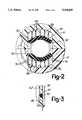
- FIG. 2is a cross-section of the motor housing showing the conical seat formed by the ends of the stiffner ribs;
- FIG. 3is a cross-section showing the relationship of the stiffner ribs to the end face member and the adjacent motor support rib.
- the motor housing 10 of a typical string trimmercomprises two molded plastic housing members 12 and 14 which are substantially mirror images of each.
- Each of the housing membershas a motor mounting portion 16 and a handle mounting portion 18.
- the handle mounting portion 18has an end closure member 20, a plurality of transverse handle support ribs 22 and a stop rib 24.
- the internal edges of the end closure member 20 and the support ribshave contoured recesses 26 in which the handle of the string trimmer is received.
- the size and shape of the contoured recesses 26are selected such that the handle is rigidly secured in the handle mounting portion 18 when the molded housing members 12 and 14 are secured to each other by bolts 30 through 38.
- Bolt 38passes through a first aperture 40 provided through the handle portion 18 of the housing member 16 through a second aperture 42 provided through the handle 28 and is threadably received in an internally threaded mounting post 48, provided in the handle portion 18 of the housing member 12.
- the bolt 38secures the handle portions 18 of the two housing members 12 and 14 to each other and prohibits the axial displacement of the handle 28 relative to the motor housing 10.
- the stop rib 24has a arcuate recess 50 which has a diameter less than the diameter of the handle 28.
- the aperture formed by the actuate recess when the two housing members 12 and 14 are secured to each otherpermits the electrical lead 52 and 54 to pass from inside the handle 28 into the interior of the motor portion 16.
- the stop rib 24axially positions the handle portion so that the aperture 42 in the handle is aligned with the aperture 40 and the internally threaded post 48.
- Each housing portion 16has a transverse internal rib 56, a plurality of transverse motor support ribs 58 through 62, and an end face rib 64.
- Each of the support ribs 58 through 62has an arcuate relief 66 which has a diameter substantially equal to the diameter of the electric motor 68.
- the electric motor 68is received in the arcuate recesses 66 and is rigidly supported in the motor housing 10 by the motor support ribs 58-62.
- the internal end rib 56 of each of the housing members 12 and 14has a radially disposed key 70 which is received in a mating slot 72 provided at the internal end of the electric motor 68.
- the keys 70prevent the motor 68 from rotating relative to the motor housing 10.
- a pair of transverse keys 74engage mating slots 76 provided in the housing of the motor 68.
- the transverse keys 74are slidably received in the space between motor support ribs 58 and 60 and prevent the axial displacement of the motor 68 relative to the motor housing 10.
- the end face member 78is disposed at the end of the motor mounting portion 16 opposite the internal end rib 56.
- Each end face member 78has a semi-circular relief 80 which when mated with a corresponding semi-circular relief 80 of the housing member 14 forms a clearance aperture in the motor housing 10 for the shaft 82 of the electric motor 68.
- the forward end 84 of the motoreffectively closes the aperture formed by the semi-circular reliefs 80.
- the housing member 12may have a plurality of thread posts 94 which threadably receive the bolts 30 through 36 to secure the housing member 14 to the housing member 12 with the electric motor 68 and the vibration damper members 92 therein.
- FIGS. 2 and 3are partial cross-sections showing a series of parallel stiffner ribs 86 extending between the end face member 78 and the motor support rib 62.
- the internal ends 90 of the parallel stiffner ribs 86form an arcuate seat for the resilient vibration damper 92.
- the vibration damper 92is a resilient linear member having the general form of a rectangular parallelopiped in its relaxed or undistorted state as shown in FIG. 1 and is compressively deformed in the motor housing 10 to engage opposite side portions of the motor 86 as shown in FIG. 2.
- the vibration dampermay have a circular cross-section or any other shape known in the art.
- the width of the vibration damper 92is substantially equal to the axial spacing between the motor support rib 62 and the end face member 78 and its height is greater than the distance between the internal ends 90 of the parallel stiffner ribs 86 and the electric motor such that the vibration dampers 92 are under compression when housing members are secured to each other using bolts 30 through 36.
- a string feeder head(not shown) is attached to the rotary output shaft 82 of the motor 68.
- the motor support ribs 65 through 62 in each of the motor housing members 12 and 14compressively engage the motor 68 and prohibit transverse movement of the motor 68 relative to the motor housing 10.
- the string feeder headis rotatively unbalanced, due to the cutting string extending radially therefrom.
- the unbalanced string feeder headimparts a vibratory force to motor 68 through the rotary output shaft 82.
- This vibratory forceis transmitted from the motor 68 to the motor housing through the motor support ribs 58 through 62. After a period of time, this vibrational force deforms the arcuate reliefs 66 on the motor support ribs 58 through 62 such that the motor is no longer rigidly supported in the motor housing 10.
- the motoris free to vibrate relative to the housing and the amplitude of vibration of the motor increases resulting in an increase of the vibratory force imparted by the motor 68 on the motor support ribs 58 through 62. This further enlarges the arcuate reliefs of the motor support ribs and increasing the amplitude of the vibration of the motor housing 10 to the point where it becomes objectionable to the user.
- the vibration dampers 92also significantly reduce the deformation of the arcuate relief of the motor support ribs.
- the vibration dampers 92not only results in a string trimmer in which the vibration transferred to the user is significantly reduced but also results in a string trimmer having an extended useful life.
Landscapes
- Engineering & Computer Science (AREA)
- Mechanical Engineering (AREA)
- Power Engineering (AREA)
- Percussion Or Vibration Massage (AREA)
Abstract
Description
Claims (24)
Priority Applications (1)
| Application Number | Priority Date | Filing Date | Title |
|---|---|---|---|
| US08/005,641US5394039A (en) | 1993-01-19 | 1993-01-19 | Electric motor mount having vibration damping |
Applications Claiming Priority (1)
| Application Number | Priority Date | Filing Date | Title |
|---|---|---|---|
| US08/005,641US5394039A (en) | 1993-01-19 | 1993-01-19 | Electric motor mount having vibration damping |
Publications (1)
| Publication Number | Publication Date |
|---|---|
| US5394039Atrue US5394039A (en) | 1995-02-28 |
Family
ID=21716929
Family Applications (1)
| Application Number | Title | Priority Date | Filing Date |
|---|---|---|---|
| US08/005,641Expired - LifetimeUS5394039A (en) | 1993-01-19 | 1993-01-19 | Electric motor mount having vibration damping |
Country Status (1)
| Country | Link |
|---|---|
| US (1) | US5394039A (en) |
Cited By (34)
| Publication number | Priority date | Publication date | Assignee | Title |
|---|---|---|---|---|
| JPH07163126A (en)* | 1993-11-30 | 1995-06-23 | Canon Inc | Lens drive stepping motor |
| US5530304A (en)* | 1993-01-20 | 1996-06-25 | Hitachi, Ltd. | Miniature motor and fan using the same |
| US5564308A (en)* | 1994-02-26 | 1996-10-15 | Mitsui Kinzoku Kogyo Kabushiki Kaisha | Actuator unit for vehicle door locking device |
| US5705864A (en)* | 1993-07-29 | 1998-01-06 | Canon Kabushiki Kaisha | Stepping motor |
| US5769174A (en)* | 1996-12-18 | 1998-06-23 | Ingersoll-Rand Company | Parallel displacement single axis vibration isolator |
| US5775138A (en)* | 1996-05-22 | 1998-07-07 | Electrolux Zanussi Elettrodomestici, S.P.A. | Arrangement for mounting the motor in a clothes washing machine |
| US6147426A (en)* | 1999-10-29 | 2000-11-14 | Ford Global Technologies, Inc. | Housing and mounting portion for an alternator |
| US6263980B1 (en)* | 1997-08-30 | 2001-07-24 | Black & Decker Inc. | Power tool |
| US6582257B1 (en) | 2001-12-17 | 2003-06-24 | Alstom | Propulsion unit |
| US20030177746A1 (en)* | 2002-03-20 | 2003-09-25 | Goman Gerald E. | Reel mower with tuned mass damper |
| US20030213530A1 (en)* | 2002-05-16 | 2003-11-20 | Ricono Thomas R. | Pencil sharpener |
| US20040216907A1 (en)* | 2002-09-20 | 2004-11-04 | Happ Kenneth C. | Power tool with air seal and vibration dampener |
| US20060013694A1 (en)* | 2004-07-13 | 2006-01-19 | Eubank Gerry E | Motor fan guard |
| EP1674215A1 (en)* | 2004-12-23 | 2006-06-28 | BLACK & DECKER INC. | Power tool housing |
| US20060201690A1 (en)* | 2005-03-09 | 2006-09-14 | Siegfried Fehrle | Electric hand-held power tool |
| US20080006424A1 (en)* | 2006-07-06 | 2008-01-10 | Honsa Thomas W | Powered hand tool |
| US20080016983A1 (en)* | 2004-07-28 | 2008-01-24 | Dietmar Saur | Intermediate Flange for a Machine Tool |
| US20080053676A1 (en)* | 2006-09-04 | 2008-03-06 | Metabowerke Gmbh | Electric Hand Held Tool Device |
| US20080223594A1 (en)* | 2005-10-29 | 2008-09-18 | Aeg Electric Tools Gmbh | Portable Power Tool |
| US20080257578A1 (en)* | 2004-12-07 | 2008-10-23 | Black & Decker Inc. | Vibration Attenuated Power Tool |
| US20090114412A1 (en)* | 2007-11-05 | 2009-05-07 | Black And Decker Inc. | Power tool having housing with enhanced impact resistance |
| US20100001604A1 (en)* | 2007-01-19 | 2010-01-07 | Calsonic Kansei Corporation | Motor-mounting structure and actuator for vehicle |
| US20100064524A1 (en)* | 2008-09-17 | 2010-03-18 | Mah Pat Y | Vibrating peeler |
| US20100083716A1 (en)* | 2008-10-03 | 2010-04-08 | Kabushiki Kaisha Tokai Rika Denki Seisakusho | Electric steering wheel lock device and motor damping structure |
| US20100101814A1 (en)* | 2007-03-28 | 2010-04-29 | Thomas Bernhardt | Hand machine tool |
| US20100193209A1 (en)* | 2008-01-25 | 2010-08-05 | Joachim Schadow | Hand-held power tool, in particular electrically driven hand-held power tool |
| US20140217748A1 (en)* | 2011-06-30 | 2014-08-07 | Kiekert Aktiengesellschaft | Actuator unit for motor vehicle applications |
| US20150108860A1 (en)* | 2013-10-17 | 2015-04-23 | Asmo Co., Ltd | Motor actuator |
| US20150144367A1 (en)* | 2012-04-24 | 2015-05-28 | C. & E. Fein Gmbh | Machine tool that can be guided manually and having a housing |
| DE102014103856A1 (en)* | 2014-03-20 | 2015-09-24 | C. & E. Fein Gmbh | Hand tool with an outer housing and an inner housing |
| US20160229038A1 (en)* | 2015-02-09 | 2016-08-11 | Panasonic Intellectual Property Management Co., Ltd. | Impact rotation tool |
| US20180029215A1 (en)* | 2015-02-15 | 2018-02-01 | Positec Power Tools (Suzhou) Co., Ltd | Power tool |
| WO2019200531A1 (en)* | 2018-04-17 | 2019-10-24 | 深圳市兆威机电股份有限公司 | Mechanism for preventing resonance and noise change of motor |
| EP2841236B1 (en)* | 2012-04-24 | 2021-01-06 | C. & E. Fein GmbH | Hand-held machine tool with outer housing |
Citations (8)
| Publication number | Priority date | Publication date | Assignee | Title |
|---|---|---|---|---|
| US3831278A (en)* | 1972-08-03 | 1974-08-27 | Dynamics Corp America | Grass trimmer |
| US3886716A (en)* | 1973-02-26 | 1975-06-03 | Rockwell International Corp | Electrically powered grass trimmer |
| US4136446A (en)* | 1977-01-24 | 1979-01-30 | Weed Eater, Inc. | Rotary cutting assembly with mechanical line feed |
| US4140446A (en)* | 1976-09-23 | 1979-02-20 | Atlas Copco Aktiebolag | Rotary pneumatic tool with vibration absorbing means |
| US4211004A (en)* | 1975-10-22 | 1980-07-08 | Emerson Electric Co. | String-type weed cutter with mechanical line feed |
| US4268233A (en)* | 1978-05-16 | 1981-05-19 | Atlas Copco Aktiebolag | Hand held rotary machine tool with vibration insulating means |
| US4635732A (en)* | 1983-09-28 | 1987-01-13 | Robert Bosch Gmbh | Power-driven hand-held tool with a pneumatic motor |
| US4905772A (en)* | 1988-09-01 | 1990-03-06 | Honsa Thomas W | Rotary power tool with vibration damping |
- 1993
- 1993-01-19USUS08/005,641patent/US5394039A/ennot_activeExpired - Lifetime
Patent Citations (8)
| Publication number | Priority date | Publication date | Assignee | Title |
|---|---|---|---|---|
| US3831278A (en)* | 1972-08-03 | 1974-08-27 | Dynamics Corp America | Grass trimmer |
| US3886716A (en)* | 1973-02-26 | 1975-06-03 | Rockwell International Corp | Electrically powered grass trimmer |
| US4211004A (en)* | 1975-10-22 | 1980-07-08 | Emerson Electric Co. | String-type weed cutter with mechanical line feed |
| US4140446A (en)* | 1976-09-23 | 1979-02-20 | Atlas Copco Aktiebolag | Rotary pneumatic tool with vibration absorbing means |
| US4136446A (en)* | 1977-01-24 | 1979-01-30 | Weed Eater, Inc. | Rotary cutting assembly with mechanical line feed |
| US4268233A (en)* | 1978-05-16 | 1981-05-19 | Atlas Copco Aktiebolag | Hand held rotary machine tool with vibration insulating means |
| US4635732A (en)* | 1983-09-28 | 1987-01-13 | Robert Bosch Gmbh | Power-driven hand-held tool with a pneumatic motor |
| US4905772A (en)* | 1988-09-01 | 1990-03-06 | Honsa Thomas W | Rotary power tool with vibration damping |
Cited By (62)
| Publication number | Priority date | Publication date | Assignee | Title |
|---|---|---|---|---|
| JP3435182B2 (en) | 1993-01-20 | 2003-08-11 | 株式会社日立製作所 | Small electric motor and blower using the same |
| US5530304A (en)* | 1993-01-20 | 1996-06-25 | Hitachi, Ltd. | Miniature motor and fan using the same |
| US5705864A (en)* | 1993-07-29 | 1998-01-06 | Canon Kabushiki Kaisha | Stepping motor |
| JPH07163126A (en)* | 1993-11-30 | 1995-06-23 | Canon Inc | Lens drive stepping motor |
| US5564308A (en)* | 1994-02-26 | 1996-10-15 | Mitsui Kinzoku Kogyo Kabushiki Kaisha | Actuator unit for vehicle door locking device |
| US5775138A (en)* | 1996-05-22 | 1998-07-07 | Electrolux Zanussi Elettrodomestici, S.P.A. | Arrangement for mounting the motor in a clothes washing machine |
| US5769174A (en)* | 1996-12-18 | 1998-06-23 | Ingersoll-Rand Company | Parallel displacement single axis vibration isolator |
| US6263980B1 (en)* | 1997-08-30 | 2001-07-24 | Black & Decker Inc. | Power tool |
| US6147426A (en)* | 1999-10-29 | 2000-11-14 | Ford Global Technologies, Inc. | Housing and mounting portion for an alternator |
| US6582257B1 (en) | 2001-12-17 | 2003-06-24 | Alstom | Propulsion unit |
| US20030139100A1 (en)* | 2001-12-17 | 2003-07-24 | Lewis Clive David | Propulsion unit |
| US6846209B2 (en)* | 2001-12-17 | 2005-01-25 | Alstom | Propulsion unit |
| US20030177746A1 (en)* | 2002-03-20 | 2003-09-25 | Goman Gerald E. | Reel mower with tuned mass damper |
| US7007448B2 (en)* | 2002-03-20 | 2006-03-07 | The Toro Company | Reel mower with tuned mass damper |
| US20030213530A1 (en)* | 2002-05-16 | 2003-11-20 | Ricono Thomas R. | Pencil sharpener |
| US6886614B2 (en) | 2002-05-16 | 2005-05-03 | Hunt Holdings, Inc. | Pencil sharpener |
| US20040216907A1 (en)* | 2002-09-20 | 2004-11-04 | Happ Kenneth C. | Power tool with air seal and vibration dampener |
| US7152695B2 (en)* | 2002-09-20 | 2006-12-26 | Snap-On Incorporated | Power tool with air seal and vibration dampener |
| US20060013694A1 (en)* | 2004-07-13 | 2006-01-19 | Eubank Gerry E | Motor fan guard |
| US7104753B2 (en) | 2004-07-13 | 2006-09-12 | Dreison International, Inc. | Motor fan guard |
| US20080016983A1 (en)* | 2004-07-28 | 2008-01-24 | Dietmar Saur | Intermediate Flange for a Machine Tool |
| US7866412B2 (en)* | 2004-12-07 | 2011-01-11 | Black & Decker Inc. | Vibration attenuated power tool |
| US20080257578A1 (en)* | 2004-12-07 | 2008-10-23 | Black & Decker Inc. | Vibration Attenuated Power Tool |
| EP1674215A1 (en)* | 2004-12-23 | 2006-06-28 | BLACK & DECKER INC. | Power tool housing |
| US20060156859A1 (en)* | 2004-12-23 | 2006-07-20 | Uwe Nemetz | Power tool housing |
| US20060201690A1 (en)* | 2005-03-09 | 2006-09-14 | Siegfried Fehrle | Electric hand-held power tool |
| US7987918B2 (en)* | 2005-03-09 | 2011-08-02 | Robert Bosch Gmbh | Electric hand-held power tool |
| US20080223594A1 (en)* | 2005-10-29 | 2008-09-18 | Aeg Electric Tools Gmbh | Portable Power Tool |
| US8496073B2 (en)* | 2005-10-29 | 2013-07-30 | Aeg Electric Tools Gmbh | Portable power tool |
| US20080006424A1 (en)* | 2006-07-06 | 2008-01-10 | Honsa Thomas W | Powered hand tool |
| US7401662B2 (en)* | 2006-07-06 | 2008-07-22 | Honsa Ergonomic Technologies, Inc. | Powered hand tool |
| US7610968B1 (en)* | 2006-07-06 | 2009-11-03 | Honsa Ergonomic Technologies, Inc. | Powered hand tool |
| US20080053676A1 (en)* | 2006-09-04 | 2008-03-06 | Metabowerke Gmbh | Electric Hand Held Tool Device |
| US20100001604A1 (en)* | 2007-01-19 | 2010-01-07 | Calsonic Kansei Corporation | Motor-mounting structure and actuator for vehicle |
| EP2060419A4 (en)* | 2007-01-19 | 2010-08-04 | Calsonic Kansei Corp | Mounting structure of motor and actuator for vehicle |
| US8662197B2 (en) | 2007-03-28 | 2014-03-04 | Robert Bosch Gmbh | Method of assembling a hand machine tool |
| US20100101814A1 (en)* | 2007-03-28 | 2010-04-29 | Thomas Bernhardt | Hand machine tool |
| US8230945B2 (en)* | 2007-03-28 | 2012-07-31 | Robert Bosch Gmbh | Hand machine tool |
| US20090114412A1 (en)* | 2007-11-05 | 2009-05-07 | Black And Decker Inc. | Power tool having housing with enhanced impact resistance |
| US20100193209A1 (en)* | 2008-01-25 | 2010-08-05 | Joachim Schadow | Hand-held power tool, in particular electrically driven hand-held power tool |
| US8205683B2 (en)* | 2008-01-25 | 2012-06-26 | Robert Bosch Gmbh | Hand-held power tool, in particular electrically driven hand-held power tool |
| US20100064524A1 (en)* | 2008-09-17 | 2010-03-18 | Mah Pat Y | Vibrating peeler |
| US20100083716A1 (en)* | 2008-10-03 | 2010-04-08 | Kabushiki Kaisha Tokai Rika Denki Seisakusho | Electric steering wheel lock device and motor damping structure |
| US8881563B2 (en)* | 2008-10-03 | 2014-11-11 | Kabushiki Kaisha Tokai Rika Denki Seisakusho | Electric steering wheel lock device and motor damping structure |
| US20140217748A1 (en)* | 2011-06-30 | 2014-08-07 | Kiekert Aktiengesellschaft | Actuator unit for motor vehicle applications |
| US9541156B2 (en)* | 2011-06-30 | 2017-01-10 | Kiekert Aktiengesellschaft | Actuator unit for motor vehicle applications |
| EP2841236B1 (en)* | 2012-04-24 | 2021-01-06 | C. & E. Fein GmbH | Hand-held machine tool with outer housing |
| US10160111B2 (en)* | 2012-04-24 | 2018-12-25 | C. & E. Fein Gmbh | Machine tool that can be guided manually and having a housing |
| US20150144367A1 (en)* | 2012-04-24 | 2015-05-28 | C. & E. Fein Gmbh | Machine tool that can be guided manually and having a housing |
| CN104578554B (en)* | 2013-10-17 | 2018-09-25 | 株式会社电装 | Motor actuator |
| US9509193B2 (en)* | 2013-10-17 | 2016-11-29 | Asmo Co., Ltd. | Motor actuator |
| CN104578554A (en)* | 2013-10-17 | 2015-04-29 | 阿斯莫株式会社 | Motor actuator |
| US20150108860A1 (en)* | 2013-10-17 | 2015-04-23 | Asmo Co., Ltd | Motor actuator |
| US20170008160A1 (en)* | 2014-03-20 | 2017-01-12 | C. & E. Fein Gmbh | Hand Tool Comprising Vibration Damping Elements |
| DE102014103856A1 (en)* | 2014-03-20 | 2015-09-24 | C. & E. Fein Gmbh | Hand tool with an outer housing and an inner housing |
| US10792802B2 (en)* | 2014-03-20 | 2020-10-06 | C. & E. Fein Gmbh | Hand tool comprising vibration damping elements |
| JP2016144845A (en)* | 2015-02-09 | 2016-08-12 | パナソニックIpマネジメント株式会社 | Impact rotary tool |
| US20160229038A1 (en)* | 2015-02-09 | 2016-08-11 | Panasonic Intellectual Property Management Co., Ltd. | Impact rotation tool |
| US10335931B2 (en)* | 2015-02-09 | 2019-07-02 | Panasonic Intellectual Property Management Co., Ltd. | Impact rotation tool |
| US20180029215A1 (en)* | 2015-02-15 | 2018-02-01 | Positec Power Tools (Suzhou) Co., Ltd | Power tool |
| US10888988B2 (en)* | 2015-02-15 | 2021-01-12 | Positec Power Tools (Suzhou) Co., Ltd | Power tool |
| WO2019200531A1 (en)* | 2018-04-17 | 2019-10-24 | 深圳市兆威机电股份有限公司 | Mechanism for preventing resonance and noise change of motor |
Similar Documents
| Publication | Publication Date | Title |
|---|---|---|
| US5394039A (en) | Electric motor mount having vibration damping | |
| US11152843B2 (en) | Electromechanical generator for converting mechanical vibrational energy into electrical energy | |
| US3845557A (en) | Chain saw anti-vibration system | |
| CN111903043A (en) | Electromechanical generator for converting mechanical vibrational energy into electrical energy | |
| EP2920869B1 (en) | Generator and method for converting vibrational energy into electrical energy | |
| US6374698B1 (en) | Vibration damping device | |
| DE19706852A1 (en) | Holding device for an electric motor | |
| JPH05116101A (en) | Chain saw in vibration damping form | |
| US11804791B2 (en) | Vibrational energy harvester with piston damping | |
| JP2017511195A (en) | Multi-function bobbin design | |
| US20110210643A1 (en) | Stator core suspension system using spring bar in plane extending perpendicular to stator core axis | |
| US1988295A (en) | Yieldable supporting structure | |
| EP0698750A1 (en) | Tuned dynamic vibration absorber | |
| WO2019185463A1 (en) | An electromechanical generator for converting mechanical vibrational energy into electrical energy | |
| US10794400B2 (en) | Fan with shock-absorbing effect | |
| US3459977A (en) | Vibration-insulating mounting | |
| US2638303A (en) | Shock mount | |
| US11619217B2 (en) | Hermetic compressor | |
| KR102191431B1 (en) | Device for decoupled holding an electric motor and apparatus for delivering an air volume flow with the device | |
| JP2017180658A (en) | Vibration control device | |
| KR100356871B1 (en) | Vibration damping apparatus | |
| JPH0235070Y2 (en) | ||
| US7571776B2 (en) | Antivibration unit of a portable handheld work apparatus | |
| JP2008511280A (en) | Brush holder for carbon brushes advantageously | |
| RU1796803C (en) | Vibration insulator |
Legal Events
| Date | Code | Title | Description |
|---|---|---|---|
| AS | Assignment | Owner name:RYOBI OUTDOOR PRODUCTS, INC., ARIZONA Free format text:ASSIGNMENT OF ASSIGNORS INTEREST;ASSIGNORS:DUCHDEV, LAKHBIR SINGH;BRINGHURST, RORY B.;BAKER, MICHAEL;REEL/FRAME:006908/0418 Effective date:19930412 | |
| STCF | Information on status: patent grant | Free format text:PATENTED CASE | |
| CC | Certificate of correction | ||
| FEPP | Fee payment procedure | Free format text:PAYOR NUMBER ASSIGNED (ORIGINAL EVENT CODE: ASPN); ENTITY STATUS OF PATENT OWNER: LARGE ENTITY | |
| FPAY | Fee payment | Year of fee payment:4 | |
| AS | Assignment | Owner name:RYOBI NORTH AMERICA, INC., SOUTH CAROLINA Free format text:ASSIGNMENT OF ASSIGNORS INTEREST;ASSIGNOR:RYOBI OUTDOOR PRODUCTS, INC.;REEL/FRAME:009827/0544 Effective date:19980303 | |
| AS | Assignment | Owner name:BANK ONE, N.A., MICHIGAN Free format text:SECURITY INTEREST;ASSIGNOR:MTD SOUTHWEST, INC.;REEL/FRAME:011284/0391 Effective date:20000614 | |
| AS | Assignment | Owner name:MTD SOUTHWEST INC., OHIO Free format text:ASSIGNMENT OF ASSIGNORS INTEREST;ASSIGNOR:RYOBI NORTH AMERICA, INC.;REEL/FRAME:011213/0044 Effective date:20000614 | |
| FPAY | Fee payment | Year of fee payment:8 | |
| FPAY | Fee payment | Year of fee payment:12 | |
| AS | Assignment | Owner name:MTD PRODUCTS INC,OHIO Free format text:ASSIGNMENT OF ASSIGNORS INTEREST;ASSIGNOR:MTD SOUTHWEST INC;REEL/FRAME:024468/0791 Effective date:20100520 |