US5393967A - Method and apparatus for non-contact reading of a relief pattern - Google Patents
Method and apparatus for non-contact reading of a relief patternDownload PDFInfo
- Publication number
- US5393967A US5393967AUS08/095,727US9572793AUS5393967AUS 5393967 AUS5393967 AUS 5393967AUS 9572793 AUS9572793 AUS 9572793AUS 5393967 AUS5393967 AUS 5393967A
- Authority
- US
- United States
- Prior art keywords
- relief pattern
- light
- optical
- pattern
- line
- Prior art date
- Legal status (The legal status is an assumption and is not a legal conclusion. Google has not performed a legal analysis and makes no representation as to the accuracy of the status listed.)
- Expired - Lifetime
Links
Images


Classifications
- G—PHYSICS
- G06—COMPUTING OR CALCULATING; COUNTING
- G06K—GRAPHICAL DATA READING; PRESENTATION OF DATA; RECORD CARRIERS; HANDLING RECORD CARRIERS
- G06K7/00—Methods or arrangements for sensing record carriers, e.g. for reading patterns
- G06K7/10—Methods or arrangements for sensing record carriers, e.g. for reading patterns by electromagnetic radiation, e.g. optical sensing; by corpuscular radiation
- G06K7/10544—Methods or arrangements for sensing record carriers, e.g. for reading patterns by electromagnetic radiation, e.g. optical sensing; by corpuscular radiation by scanning of the records by radiation in the optical part of the electromagnetic spectrum
- G06K7/10821—Methods or arrangements for sensing record carriers, e.g. for reading patterns by electromagnetic radiation, e.g. optical sensing; by corpuscular radiation by scanning of the records by radiation in the optical part of the electromagnetic spectrum further details of bar or optical code scanning devices
- G06K7/10861—Methods or arrangements for sensing record carriers, e.g. for reading patterns by electromagnetic radiation, e.g. optical sensing; by corpuscular radiation by scanning of the records by radiation in the optical part of the electromagnetic spectrum further details of bar or optical code scanning devices sensing of data fields affixed to objects or articles, e.g. coded labels
- G—PHYSICS
- G06—COMPUTING OR CALCULATING; COUNTING
- G06K—GRAPHICAL DATA READING; PRESENTATION OF DATA; RECORD CARRIERS; HANDLING RECORD CARRIERS
- G06K19/00—Record carriers for use with machines and with at least a part designed to carry digital markings
- G06K19/06—Record carriers for use with machines and with at least a part designed to carry digital markings characterised by the kind of the digital marking, e.g. shape, nature, code
- G06K19/06009—Record carriers for use with machines and with at least a part designed to carry digital markings characterised by the kind of the digital marking, e.g. shape, nature, code with optically detectable marking
- G06K19/06018—Record carriers for use with machines and with at least a part designed to carry digital markings characterised by the kind of the digital marking, e.g. shape, nature, code with optically detectable marking one-dimensional coding
- G06K19/06028—Record carriers for use with machines and with at least a part designed to carry digital markings characterised by the kind of the digital marking, e.g. shape, nature, code with optically detectable marking one-dimensional coding using bar codes
- G—PHYSICS
- G06—COMPUTING OR CALCULATING; COUNTING
- G06K—GRAPHICAL DATA READING; PRESENTATION OF DATA; RECORD CARRIERS; HANDLING RECORD CARRIERS
- G06K7/00—Methods or arrangements for sensing record carriers, e.g. for reading patterns
- G06K7/10—Methods or arrangements for sensing record carriers, e.g. for reading patterns by electromagnetic radiation, e.g. optical sensing; by corpuscular radiation
- G06K7/10544—Methods or arrangements for sensing record carriers, e.g. for reading patterns by electromagnetic radiation, e.g. optical sensing; by corpuscular radiation by scanning of the records by radiation in the optical part of the electromagnetic spectrum
- G06K7/10554—Moving beam scanning
- G06K7/10594—Beam path
- G—PHYSICS
- G06—COMPUTING OR CALCULATING; COUNTING
- G06K—GRAPHICAL DATA READING; PRESENTATION OF DATA; RECORD CARRIERS; HANDLING RECORD CARRIERS
- G06K19/00—Record carriers for use with machines and with at least a part designed to carry digital markings
- G06K19/06—Record carriers for use with machines and with at least a part designed to carry digital markings characterised by the kind of the digital marking, e.g. shape, nature, code
- G06K2019/06215—Aspects not covered by other subgroups
- G06K2019/06271—Relief-type marking
Definitions
- This inventionrelates in general to pattern recognition and in particular to a method and a system for noncontact reading of product or part identification patterns, and more specifically to reading of patterns which are present in relief form.
- bar codesfor identification of parts and products are widespread.
- the most common means of including a bar code for an objectis to either affix a printed label, or to print-the code directly on the part or product.
- Most conventional bar code scannersrequire very high contrast between the bars and the background in order to properly read the code.
- affixing a label or painting a codeis either impractical or too expensive. For example, some surfaces will not allow labels to adhere properly or the presence of a label may interfere with the proper operation of the part.
- a non-contact apparatusfor reading a surface that has information encoded in a relief pattern thereon, the relief pattern having relatively raised and recessed portions.
- the apparatuscomprises an optical transmitter for projecting a line of light onto the relief pattern at a first angle to a normal of the surface; an optical receiver that views the projected line of light at a second angle to the normal of the surface and produces a signal that is representative of an image of the reflection thereon.
- the imageincorporates apparent displacements of the line of illumination that occur at transitions between raised and recessed portions of the relief pattern therealong.
- the displacementsare detected by a pattern detector which is coupled to the optical receiver.
- the output of the pattern detectoris submitted to a decoder for converting a pattern of detected apparent or parallactic displacements into electrical signals which represent the decoded information contained in the relief pattern.
- the optical receiver and the optical transmitterare spaced apart in a plane that is substantially parallel to the surface.
- the decoder and pattern detectorare realized by a digitizer and a microprocessor having a suitable program stored therein.
- the optical receivercan be realized as a plurality of light sensors arranged in a two dimensional array, each having an output responsive to light energy incident thereon, and including optical means for projecting a focused image of the reflection on the sensors.
- the light sensorscan be arranged in a linear array and the optical transmitter configured to sweep a spot of light across the relief pattern to define a substantially rectangular area thereon, a cross sectional dimension of the spot being less than the width of the smallest feature in the relief pattern in order to achieve a desired resolution.
- Apparent displacements of the line of illumination on the surfaceare represented by displacements of the focused image along the linear array.
- FIG. 1illustrates a block diagram of a relief pattern reading apparatus in accordance with the invention
- FIG. 2illustrates a swept column beam of light impinging on a flat surface
- FIG. 3illustrates a fan beam of light impinging on a flat surface
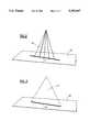
- FIG. 4illustrates a swept column or fan of illumination impinging on a relief patterned surface
- FIG. 5is an enlarged perspective view of a surface bearing a relief pattern which has been exaggerated for clarity to illustrate parallactic displacements of a line of illumination;
- FIG. 5ais an enlarged fragmentary perspective view of FIG. 5 taken on line 5a-5a;
- FIG. 6is a diagram that illustrates a mapping of an image of the line of illumination on the surface shown in FIG. 5 onto a two-dimensional photodetector array in an optical receiver;
- FIG. 7diagrammatically illustrates a mapping of an image of a line of illumination generated by sweeping a beam of light across the surface shown in FIG. 5 onto a linear photodetector array
- FIG. 8schematically illustrates an alternate optical arrangement for mapping the image onto the photodetector array of FIGS. 6 and 7;
- FIG. 1there is depicted a representation of a relief pattern reading apparatus 1, in accordance with a preferred embodiment of the invention, positioned near an object surface containing a relief pattern 8.
- the relief pattern reading apparatus 1includes an optical transmitter 2, an optical receiver 3, a pattern detector 4, and a decoder 5.
- a preferred embodiment of the present inventionmay be implemented with the components 2, 3, 4, 5 in a single unit, or with any or all of the components 2, 3, 4, 5 in separate enclosures.
- the optical transmitter 2emits a beam of light 6 which impinges on the object surface containing the relief pattern 8.
- the beam of light 6 emitted from the optical transmitter 2can be either a spot beam which is swept or scanned, or the beam of light 6 may be a stationary beam. In either case, the beam, if projected onto a flat surface, would appear as a line of light. Alternate methods of illuminating the surface are shown respectively in FIGS. 2 and 3, wherein the light beams are diagrammatically shown as originating from a source in the optical transmitter 2, the structural details of which have been omitted for clarity.
- FIG. 2there is depicted a spot beam of light 10, which is swept or scanned to form a line 11 when projected onto a flat surface 12. Representative positions of the beam 10 as the spot moves across the surface are indicated by the series of dotted lines in FIG. 2.
- FIG. 3there is depicted a fan beam of light 13, which forms a line 14 when projected onto the flat surface 15.
- the optical receiver 3is positioned such that its field of view 7 contains the projected image of the line of illumination produced by the beam of light 6 on the surface 8.
- the optical receiver 3converts the image in its field of view 7 into electrical signals which can be processed by the pattern detector 4.
- the pattern detector 4extracts the coded pattern from the electrical representation of the image and sends the coded pattern to the decoder 5 for decoding.
- This representationmay be a digitized signal as is known to the decoding art, or could be in other well known formats.
- the decoder 5decodes the coded pattern to extract the character string or other information which was encoded into the relief pattern.
- the decoder 5uses techniques well known in the art to decode the coded pattern, and as such is not a subject of the present invention.
- the decoder 5outputs the decoded character string or information to a display or similar conventional device using a communications port 9. This communications port 9 may take many forms and is also not a subject of the present invention.
- the optical transmitter 2In order for the components in FIG. 1 to be utilized in reading relief patterns, the optical transmitter 2 must be separated from the optical receiver 3 by some distance. Referring to FIG. 4, the swept spot or fan illumination 16 generated by the optical transmitter 2 impinges upon the relief pattern 8 forming what appears from the viewpoint of the optical transmitter 2 to be a straight line.
- the optical receiver 3is positioned such that its direction of view 17 is as shown in FIG. 4.
- FIG. 5depicts the image of the relief pattern surface 8 as seen from the point of view of the optical receiver 3. Because of the separation of the optical transmitter 2 and the optical receiver 3, those portions of the illuminated surface 18 which are on the raised portions of the pattern exhibit a parallactic displacement 20 from those portions of the illuminated surface 19 on the lower portions of the pattern. It is this parallactic displacement 20 which is detected by the pattern detector 4.
- FIG. 5aa line of illumination, indicated generally by reference numeral 40, has a segment 18 that crosses a relatively raised zone 28 of the relief pattern, and a substantially vertical segment 41, representing a transition between raised portion 28 and relatively recessed zone 29.
- Line 40continues horizontally along zone 29 as segment 19.
- An angularly displaced observersuch as optical receiver 3 in FIG. 1, views the relief pattern along line 42.
- Such an observerwould perceive segment 18, and segment 19' (shown as a dotted line in FIG. 5a) as collinear, as the angular displacement ⁇ of these segments from the observer's optical axis 45 is identical.
- optical receiver 3can be constructed using either a linear array of photodetectors or a square or rectangular two-dimensional array of photodetectors. Any conventional photodetector array such as a CCD array is suitable.
- optical receiver 3schematically enclosed by the dashed line in FIG. 6, comprises imaging lens 21 and two-dimensional array of photodetectors 22. Imaging lens 21 collects light from the illuminated portions of surface 8, and focuses the light to form an image on two-dimensional array of photodetectors 22.
- the parallactic displacement 20is translated by imaging lens 21 into a displacement in the direction arrow 23 on the two-dimensional array of photodetectors 22.
- This image containing the displacementis translated by two-dimensional array of photodetectors 22 into an electrical representation of the image which is sent to the pattern detector for further processing.
- This optical receiver configurationcan use either a swept spot beam or a fixed fan beam implementation of the optical transmitter 2.
- FIG. 7depicts an alternative embodiment of the optical receiver in accordance with the invention.
- optical receiver 73comprises a lens system 24, which can be a cylindrical lens, and a linear array of photodetectors 25.
- This embodimentrequires the use of the swept spot beam implementation of the optical transmitter 2.
- the lens system 24focuses light from the relief surface onto the linear array 25 such that each element or cell of the linear array 25 collects light from an area of the surface that is approximately parallel to the direction of the illuminating beam's image.
- the parallactic displacement 20is therefore translated by the lens system 24 into a displacement on the linear array of photodetectors 25 in the direction of arrow 26.
- the photodetector cell with the highest intensitycorresponds to the position of the surface that the spot beam is incident upon.
- the optical receiver 73generates an electrical representation of the current position of the spot which, when sampled over the entire sweep of the spot, directly indicates the relative height of the relief at each sample point. This information is sent to the pattern detector 4 for further processing.
- Decoder 5 and pattern detector 4are known in the art, and as they form no part of the present invention, they will not be further discussed herein.
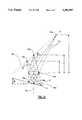
- FIG. 8there is shown an alternate embodiment of the arrangement of FIGS. 6 and 7.
- a lens systemshown as lens 74 has an optical axis 72.
- the lens systemcan be a single element, or can be a combination as is appropriate for a given application.
- An image plane 71'is defined which is substantially normal to the optical axis 72.
- Individual surfaces being scanned by the systemhave a bar coded symbol thereon, possible locations of which are indicated by lines 75a-75c. The remainder of the surfaces on which the bar code symbols are located have been omitted for clarity. It is understood that while three bar code symbol locations from three different surfaces are illustrated, only one surface is scanned at any one time.
- the bar code symbolmay be the same symbol as shown in FIGS. 6 and 7.
- a fan beam of lightis projected, preferably by a laser, striking the surface and the bar code symbols.
- the bar code symbols being scannedwill not lie on the optical axis 72, so that light rays striking points 75a-75c do not travel equal distances from the light source.
- Reflected light from the scanned surfacesis collected by lens 74, the principal rays being indicated by the dotted lines 79, 79, 81, 81 and solid lines 83, 83, and then projected generally towards a photodetector array 71 which can be linear or two-dimensional.
- the photodetector array 71is tilted from the normal of optical axis 72 at a tilt angle ⁇ , so that points 76a-76c all fall approximately on the array 71.
- the angle ⁇is readily calculated to minimize the distances of points such as 76a-76c from the actual position of array 71 using the equations of lens 74, or it may be determined empirically.
- the laser lightis actually a fan beam, and the three dimensional surfaces that include points 75a-75c have been omitted for clarity. Tilting the array 71 with respect to the image plane 71' substantially increases the functional depth of field of the system. It will be apparent that points on other three dimensional surfaces (not shown) that lie intermediate points 75a and 75c will be focused on a pixel element somewhere on array 71.
Landscapes
- Physics & Mathematics (AREA)
- Engineering & Computer Science (AREA)
- Electromagnetism (AREA)
- General Physics & Mathematics (AREA)
- Theoretical Computer Science (AREA)
- Health & Medical Sciences (AREA)
- General Health & Medical Sciences (AREA)
- Toxicology (AREA)
- Artificial Intelligence (AREA)
- Computer Vision & Pattern Recognition (AREA)
- Facsimile Scanning Arrangements (AREA)
- Image Input (AREA)
Abstract
Description
Claims (15)
Priority Applications (8)
| Application Number | Priority Date | Filing Date | Title |
|---|---|---|---|
| US08/095,727US5393967A (en) | 1993-07-21 | 1993-07-21 | Method and apparatus for non-contact reading of a relief pattern |
| EP94923962AEP0710382B1 (en) | 1993-07-21 | 1994-07-14 | Apparatus for non-contact reading of a relief pattern |
| CA002167484ACA2167484C (en) | 1993-07-21 | 1994-07-14 | Method and apparatus for non-contact reading of a relief pattern |
| BR9407086ABR9407086A (en) | 1993-07-21 | 1994-07-14 | Apparatus and process for non-contact reading of a surface that has information encoded in an embossed configuration |
| PCT/US1994/008088WO1995003590A1 (en) | 1993-07-21 | 1994-07-14 | Method and apparatus for non-contact reading of a relief pattern |
| JP50525295AJP3616096B2 (en) | 1993-07-21 | 1994-07-14 | Relief pattern non-contact reader |
| DE69422043TDE69422043T2 (en) | 1993-07-21 | 1994-07-14 | DEVICE FOR CONTACTLY READING A RELIEF PATTERN |
| US08/395,420US5677522A (en) | 1993-07-21 | 1995-02-27 | Method and apparatus for non-contact reading of a relief pattern |
Applications Claiming Priority (1)
| Application Number | Priority Date | Filing Date | Title |
|---|---|---|---|
| US08/095,727US5393967A (en) | 1993-07-21 | 1993-07-21 | Method and apparatus for non-contact reading of a relief pattern |
Related Child Applications (1)
| Application Number | Title | Priority Date | Filing Date |
|---|---|---|---|
| US08/395,420Continuation-In-PartUS5677522A (en) | 1993-07-21 | 1995-02-27 | Method and apparatus for non-contact reading of a relief pattern |
Publications (1)
| Publication Number | Publication Date |
|---|---|
| US5393967Atrue US5393967A (en) | 1995-02-28 |
Family
ID=22253317
Family Applications (2)
| Application Number | Title | Priority Date | Filing Date |
|---|---|---|---|
| US08/095,727Expired - LifetimeUS5393967A (en) | 1993-07-21 | 1993-07-21 | Method and apparatus for non-contact reading of a relief pattern |
| US08/395,420Expired - Fee RelatedUS5677522A (en) | 1993-07-21 | 1995-02-27 | Method and apparatus for non-contact reading of a relief pattern |
Family Applications After (1)
| Application Number | Title | Priority Date | Filing Date |
|---|---|---|---|
| US08/395,420Expired - Fee RelatedUS5677522A (en) | 1993-07-21 | 1995-02-27 | Method and apparatus for non-contact reading of a relief pattern |
Country Status (6)
| Country | Link |
|---|---|
| US (2) | US5393967A (en) |
| EP (1) | EP0710382B1 (en) |
| JP (1) | JP3616096B2 (en) |
| BR (1) | BR9407086A (en) |
| DE (1) | DE69422043T2 (en) |
| WO (1) | WO1995003590A1 (en) |
Cited By (33)
| Publication number | Priority date | Publication date | Assignee | Title |
|---|---|---|---|---|
| WO1998025226A1 (en)* | 1996-12-03 | 1998-06-11 | Intermec Technologies Corporation | Method and apparatus for decoding unresolved profiles produced from relief formed symbols |
| US5811777A (en)* | 1996-07-11 | 1998-09-22 | Intermec Corporation | Method and apparatus for utilizing specular light to image low contrast symbols |
| US5844222A (en)* | 1996-07-02 | 1998-12-01 | Intermec Corporation | Rastering laser scanner with beam location feedback |
| US6330974B1 (en) | 1996-03-29 | 2001-12-18 | Intermec Ip Corp. | High resolution laser imager for low contrast symbology |
| US6367699B2 (en) | 1996-07-11 | 2002-04-09 | Intermec Ip Corp. | Method and apparatus for utilizing specular light to image low contrast symbols |
| US6406227B1 (en) | 1997-07-31 | 2002-06-18 | Machine Magic Llc | Key measurement apparatus and method |
| US6582197B2 (en) | 2001-02-22 | 2003-06-24 | Simon E. Coulson | Method of investment casting with casting identification |
| EP1061466A3 (en)* | 1999-06-10 | 2003-07-16 | Konica Corporation | Optical pickup device and optical type surface displacement detecting apparatus |
| WO2003058544A1 (en)* | 2002-01-03 | 2003-07-17 | Robotic Vision System, Inc. | Apparatus and methods to apply human and/or encoded machine readable identification to parts |
| US6719468B2 (en) | 2001-02-21 | 2004-04-13 | Raymond P. Gatta | Positive piece engagement indicator for marking tool |
| US20040197443A1 (en)* | 2001-11-02 | 2004-10-07 | Paolo Scarabelli | Sheet material for producing packages of food products, and packages made of such material |
| US20060224128A1 (en)* | 2005-02-01 | 2006-10-05 | Kent Lurvey | Infusion delivery system |
| US7159780B2 (en) | 2002-07-08 | 2007-01-09 | Veritec, Inc. | Method for reading a symbol having encoded information |
| US20070108288A1 (en)* | 2005-11-16 | 2007-05-17 | Caskey Gregory T | Method and apparatus for novel reading of surface structure bar codes |
| US20110024506A1 (en)* | 2004-12-21 | 2011-02-03 | Laurens Nunnink | Low profile illumination for direct part mark readers |
| US20110132778A1 (en)* | 2006-02-25 | 2011-06-09 | Austera John T | Test element coding apparatuses, systems and methods |
| US7975913B2 (en) | 2006-08-22 | 2011-07-12 | Rynne Group, Llc | Discernment card and a discernment card business system using the discernment card |
| US8038538B2 (en) | 2004-06-04 | 2011-10-18 | Mattel, Inc. | Electronic device for enhancing an interactive experience with a tangible medium of expression |
| US20120022680A1 (en)* | 2008-06-26 | 2012-01-26 | Sumitomo Metal Industries, Ltd. | Two-dimensional code reading device, two-dimensional code reading method, method of controlling manufacturing history information of member having substantially circular section orthogonal to the central axis thereof, and method of manufacturing the member using the control method |
| US8342405B2 (en) | 2003-10-24 | 2013-01-01 | Cognex Technology And Investment Corporation | Light pipe illumination system and method |
| US8448866B2 (en) | 2006-02-25 | 2013-05-28 | Roche Diagnostics Operations, Inc. | Analyte disposable means and device for reading information |
| US8740078B2 (en) | 2003-10-24 | 2014-06-03 | Cognex Technology And Investment Corporation | Method and apparatus for providing omnidirectional lighting in a scanning device |
| US9070031B2 (en) | 2003-10-24 | 2015-06-30 | Cognex Technology And Investment Llc | Integrated illumination assembly for symbology reader |
| US9292724B1 (en) | 2004-12-16 | 2016-03-22 | Cognex Corporation | Hand held symbology reader illumination diffuser with aimer optics |
| US9405951B2 (en) | 2005-10-24 | 2016-08-02 | Cognex Technology And Investment Llc | Integrated illumination assembly for symbology reader |
| US9514385B2 (en) | 2009-05-01 | 2016-12-06 | Hy-Ko Products Company | Key blank identification system with groove scanning |
| US9536124B1 (en) | 2003-10-24 | 2017-01-03 | Cognex Corporation | Integrated illumination assembly for symbology reader |
| US9582734B2 (en) | 2009-05-01 | 2017-02-28 | Hy-Ko Products Company | Key blank identification system with bitting analysis |
| US9656332B2 (en) | 2006-01-23 | 2017-05-23 | Hy-Ko Products Company | Key duplication machine |
| US9682432B2 (en) | 2006-01-23 | 2017-06-20 | Hy-Ko Products Company | Key duplication machine |
| US9818041B2 (en) | 2015-08-03 | 2017-11-14 | Hy-Ko Products Company | High security key scanning system |
| US9948395B2 (en)* | 2016-09-12 | 2018-04-17 | The United States Of America As Represented By Secretary Of The Navy | System and method for line-of-sight optical broadcasting using beam divergence and an orbiting or airborne corner cube reflector |
| US12260289B2 (en)* | 2019-06-12 | 2025-03-25 | Philip Morris Products S.A. | Aerosol-generating article comprising three dimensional code |
Families Citing this family (41)
| Publication number | Priority date | Publication date | Assignee | Title |
|---|---|---|---|---|
| US5831254A (en)* | 1995-12-18 | 1998-11-03 | Welch Allyn, Inc. | Exposure control apparatus for use with optical readers |
| US6346988B1 (en)* | 1997-08-01 | 2002-02-12 | Hama Sensors, Inc. | Laser position array optical measuring system and method |
| US6173213B1 (en) | 1998-05-11 | 2001-01-09 | Ellison Machinery Company | Motorized inbound laser orientation and wheel recognition station |
| US7100832B2 (en)* | 2000-04-18 | 2006-09-05 | Metrologic Instruments, Inc. | Bioptical laser scanning system providing 360° of omnidirectional bar code symbol scanning coverage at point of sale station |
| US20030132291A1 (en)* | 2002-01-11 | 2003-07-17 | Metrologic Instruments, Inc. | Point of sale (POS) station having bar code reading system with integrated internet-enabled customer-kiosk terminal |
| JP2002077614A (en)* | 2000-08-25 | 2002-03-15 | Seiko Epson Corp | Black reference data calculation method and image reading device |
| US6369879B1 (en) | 2000-10-24 | 2002-04-09 | The Regents Of The University Of California | Method and apparatus for determining the coordinates of an object |
| US7128266B2 (en) | 2003-11-13 | 2006-10-31 | Metrologic Instruments. Inc. | Hand-supportable digital imaging-based bar code symbol reader supporting narrow-area and wide-area modes of illumination and image capture |
| US7464877B2 (en) | 2003-11-13 | 2008-12-16 | Metrologic Instruments, Inc. | Digital imaging-based bar code symbol reading system employing image cropping pattern generator and automatic cropped image processor |
| US8042740B2 (en) | 2000-11-24 | 2011-10-25 | Metrologic Instruments, Inc. | Method of reading bar code symbols on objects at a point-of-sale station by passing said objects through a complex of stationary coplanar illumination and imaging planes projected into a 3D imaging volume |
| US7490774B2 (en) | 2003-11-13 | 2009-02-17 | Metrologic Instruments, Inc. | Hand-supportable imaging based bar code symbol reader employing automatic light exposure measurement and illumination control subsystem integrated therein |
| US7594609B2 (en) | 2003-11-13 | 2009-09-29 | Metrologic Instruments, Inc. | Automatic digital video image capture and processing system supporting image-processing based code symbol reading during a pass-through mode of system operation at a retail point of sale (POS) station |
| US7540424B2 (en) | 2000-11-24 | 2009-06-02 | Metrologic Instruments, Inc. | Compact bar code symbol reading system employing a complex of coplanar illumination and imaging stations for omni-directional imaging of objects within a 3D imaging volume |
| US7607581B2 (en) | 2003-11-13 | 2009-10-27 | Metrologic Instruments, Inc. | Digital imaging-based code symbol reading system permitting modification of system features and functionalities |
| US7708205B2 (en) | 2003-11-13 | 2010-05-04 | Metrologic Instruments, Inc. | Digital image capture and processing system employing multi-layer software-based system architecture permitting modification and/or extension of system features and functions by way of third party code plug-ins |
| ES2184644B1 (en)* | 2001-09-20 | 2004-10-16 | Eines Informatica, S.C.V. | SHADOW CODE READER. |
| US6573523B1 (en)* | 2001-12-12 | 2003-06-03 | Lsi Logic Corporation | Substrate surface scanning |
| AU2002367381A1 (en)* | 2001-12-31 | 2003-07-24 | Bae Systems Information And Electronic Systems Integration Inc. | System for peak detection among multiple signals |
| US7296748B2 (en) | 2002-01-11 | 2007-11-20 | Metrologic Instruments, Inc. | Bioptical laser scanning system providing 360° of omnidirectional bar code symbol scanning coverage at point of sale station |
| US7549066B2 (en)* | 2002-11-15 | 2009-06-16 | Intel Corporation | Automatic power savings stand-by control for non-volatile memory |
| US7841533B2 (en) | 2003-11-13 | 2010-11-30 | Metrologic Instruments, Inc. | Method of capturing and processing digital images of an object within the field of view (FOV) of a hand-supportable digitial image capture and processing system |
| US7353999B2 (en)* | 2004-01-16 | 2008-04-08 | The Code Corporation | Graphical code reader configured for data collection and decoding |
| US7370802B2 (en)* | 2004-02-07 | 2008-05-13 | Siemens Energy & Automation, Inc. | Hand held scanner with rotating head |
| US7555741B1 (en)* | 2006-09-13 | 2009-06-30 | Altera Corporation | Computer-aided-design tools for reducing power consumption in programmable logic devices |
| US7604181B2 (en) | 2006-12-28 | 2009-10-20 | Align Technology, Inc. | System for processing mass-fabricated items with three-dimensional codes |
| US8608076B2 (en)* | 2008-02-12 | 2013-12-17 | Datalogic ADC, Inc. | Monolithic mirror structure for use in a multi-perspective optical code reader |
| US8353457B2 (en)* | 2008-02-12 | 2013-01-15 | Datalogic ADC, Inc. | Systems and methods for forming a composite image of multiple portions of an object from multiple perspectives |
| US8678287B2 (en)* | 2008-02-12 | 2014-03-25 | Datalogic ADC, Inc. | Two-plane optical code reader for acquisition of multiple views of an object |
| EP2248069B1 (en) | 2008-02-12 | 2013-08-28 | Datalogic ADC, Inc. | Systems and methods for forming a composite image of multiple portions of an object from multiple perspectives |
| US8261990B2 (en)* | 2008-12-26 | 2012-09-11 | Datalogic ADC, Inc. | Data reader having compact arrangement for acquisition of multiple views of an object |
| US8322621B2 (en)* | 2008-12-26 | 2012-12-04 | Datalogic ADC, Inc. | Image-based code reader for acquisition of multiple views of an object and methods for employing same |
| SMT201900157T1 (en)* | 2010-07-22 | 2019-05-10 | K Fee System Gmbh | Portion capsule having an identifier |
| US8523076B2 (en) | 2012-01-10 | 2013-09-03 | Metrologic Instruments, Inc. | Omnidirectional laser scanning bar code symbol reader generating a laser scanning pattern with a highly non-uniform scan density with respect to line orientation |
| DE102012105282A1 (en) | 2012-06-18 | 2013-12-19 | K-Fee System Gmbh | Portion capsule and method of making a beverage with a portion capsule |
| DE102012223291A1 (en) | 2012-12-14 | 2014-06-18 | K-Fee System Gmbh | Portion capsule and method of making a beverage with a portion capsule |
| WO2016135105A1 (en) | 2015-02-27 | 2016-09-01 | K-Fee System Gmbh | Single serve capsule comprising a filter element connected thereto by sealing |
| PT3307647T (en) | 2015-06-10 | 2019-10-28 | K Fee System Gmbh | Capsule with a three layer fleece |
| WO2017009369A1 (en) | 2015-07-13 | 2017-01-19 | K-Fee System Gmbh | Filter element having a cut-out |
| WO2017046352A1 (en) | 2015-09-18 | 2017-03-23 | K-Fee System Gmbh | Adapter for a single serve capsule |
| CN107784246A (en)* | 2017-09-28 | 2018-03-09 | 珠海市领创智能物联网研究院有限公司 | A kind of Internet of Things information collecting device |
| US12227323B2 (en) | 2018-07-27 | 2025-02-18 | Gcs German Capsule Solution Gmbh | Method for producing a portion capsule |
Citations (8)
| Publication number | Priority date | Publication date | Assignee | Title |
|---|---|---|---|---|
| NL167252B (en)* | 1951-03-22 | North American Rockwell | DEVICE FOR ELECTRO-OPTICAL SCANNING OF A RELIEF PATTERN. | |
| US4282425A (en)* | 1979-07-25 | 1981-08-04 | Norand Corporation | Instant portable bar code reader |
| JPS59165180A (en)* | 1983-03-10 | 1984-09-18 | Yokohama Rubber Co Ltd:The | Reading method of bar code for tire selection |
| JPH01255083A (en)* | 1988-04-04 | 1989-10-11 | Kawasaki Heavy Ind Ltd | Recording structure for optical reading and manufacturing method thereof |
| US5059776A (en)* | 1988-09-30 | 1991-10-22 | Lgz Landis & Gyr Zug Ag | Bar code field and bar code reader |
| JPH0434682A (en)* | 1990-05-31 | 1992-02-05 | Oputeikon:Kk | Bar code for discriminating article |
| JPH0458380A (en)* | 1990-06-27 | 1992-02-25 | Sumitomo Electric Ind Ltd | Bar code reader |
| US5258605A (en)* | 1990-03-13 | 1993-11-02 | Symbol Technologies, Inc. | Scan generators for bar code reader using linear array of lasers |
Family Cites Families (21)
| Publication number | Priority date | Publication date | Assignee | Title |
|---|---|---|---|---|
| US3751636A (en)* | 1972-06-01 | 1973-08-07 | Rca Corp | Signal transition detection circuit |
| FR2262834B1 (en)* | 1973-04-09 | 1977-10-21 | Calspan Corp | |
| JPS55115164A (en)* | 1979-02-28 | 1980-09-04 | Hitachi Ltd | Optical information reader |
| US4589034A (en)* | 1980-12-05 | 1986-05-13 | Canon Kabushiki Kaisha | Image processing apparatus |
| US4404593A (en)* | 1981-08-27 | 1983-09-13 | Rca Corporation | Brightness control circuit |
| FR2538142B1 (en)* | 1982-12-20 | 1989-06-02 | Siderurgie Fse Inst Rech | METHOD FOR IDENTIFYING METALLURGICAL PRODUCTS AND DEVICE FOR IMPLEMENTING IT |
| US4731861A (en)* | 1983-08-26 | 1988-03-15 | Texas Instruments Incorporated | Method of optical character recognition |
| US4521678A (en)* | 1984-01-13 | 1985-06-04 | Databar Corporation | Battery-powered optical bar code reader and voltage regulator therefor |
| US4625101A (en)* | 1984-02-27 | 1986-11-25 | The Goodyear Tire & Rubber Company | Bar code configuration and method of molding |
| JPS62184908A (en)* | 1986-02-07 | 1987-08-13 | Bridgestone Corp | Automatic discriminating method of tire |
| US4694182A (en)* | 1986-02-27 | 1987-09-15 | Spectra-Physics, Inc. | Hand held bar code reader with modulated laser diode and detector |
| US4724322A (en)* | 1986-03-03 | 1988-02-09 | Applied Materials, Inc. | Method for non-contact xyz position sensing |
| JPH0740284B2 (en)* | 1986-09-09 | 1995-05-01 | 日本電装株式会社 | Optical information reader |
| US4750210A (en)* | 1986-12-16 | 1988-06-07 | Tektronix, Inc. | Method and apparatus for finding objects within a visual display |
| ATE98795T1 (en)* | 1988-09-30 | 1994-01-15 | Landis & Gyr Business Support | DIFFRACTION ELEMENT. |
| JPH05224579A (en)* | 1991-11-08 | 1993-09-03 | Shoei Insatsu Kk | Correctness recognizing method, and seal and recognition device used for the same |
| US5331176A (en)* | 1992-04-10 | 1994-07-19 | Veritec Inc. | Hand held two dimensional symbol reader with a symbol illumination window |
| US5327171A (en)* | 1992-05-26 | 1994-07-05 | United Parcel Service Of America, Inc. | Camera system optics |
| US5357093A (en)* | 1993-02-01 | 1994-10-18 | Storage Technology Corporation | System and method for converting bar code scan line data into machine-readable code |
| US5408080A (en)* | 1993-02-09 | 1995-04-18 | Opticon Inc. | Electronically triggered bar code scanner |
| JP3240750B2 (en)* | 1993-06-03 | 2001-12-25 | ソニー株式会社 | Binarization circuit and solid-state imaging device |
- 1993
- 1993-07-21USUS08/095,727patent/US5393967A/ennot_activeExpired - Lifetime
- 1994
- 1994-07-14BRBR9407086Apatent/BR9407086A/enactiveSearch and Examination
- 1994-07-14EPEP94923962Apatent/EP0710382B1/ennot_activeExpired - Lifetime
- 1994-07-14DEDE69422043Tpatent/DE69422043T2/ennot_activeExpired - Fee Related
- 1994-07-14WOPCT/US1994/008088patent/WO1995003590A1/enactiveIP Right Grant
- 1994-07-14JPJP50525295Apatent/JP3616096B2/ennot_activeExpired - Fee Related
- 1995
- 1995-02-27USUS08/395,420patent/US5677522A/ennot_activeExpired - Fee Related
Patent Citations (8)
| Publication number | Priority date | Publication date | Assignee | Title |
|---|---|---|---|---|
| NL167252B (en)* | 1951-03-22 | North American Rockwell | DEVICE FOR ELECTRO-OPTICAL SCANNING OF A RELIEF PATTERN. | |
| US4282425A (en)* | 1979-07-25 | 1981-08-04 | Norand Corporation | Instant portable bar code reader |
| JPS59165180A (en)* | 1983-03-10 | 1984-09-18 | Yokohama Rubber Co Ltd:The | Reading method of bar code for tire selection |
| JPH01255083A (en)* | 1988-04-04 | 1989-10-11 | Kawasaki Heavy Ind Ltd | Recording structure for optical reading and manufacturing method thereof |
| US5059776A (en)* | 1988-09-30 | 1991-10-22 | Lgz Landis & Gyr Zug Ag | Bar code field and bar code reader |
| US5258605A (en)* | 1990-03-13 | 1993-11-02 | Symbol Technologies, Inc. | Scan generators for bar code reader using linear array of lasers |
| JPH0434682A (en)* | 1990-05-31 | 1992-02-05 | Oputeikon:Kk | Bar code for discriminating article |
| JPH0458380A (en)* | 1990-06-27 | 1992-02-25 | Sumitomo Electric Ind Ltd | Bar code reader |
Cited By (55)
| Publication number | Priority date | Publication date | Assignee | Title |
|---|---|---|---|---|
| US6330974B1 (en) | 1996-03-29 | 2001-12-18 | Intermec Ip Corp. | High resolution laser imager for low contrast symbology |
| US5844222A (en)* | 1996-07-02 | 1998-12-01 | Intermec Corporation | Rastering laser scanner with beam location feedback |
| US5811777A (en)* | 1996-07-11 | 1998-09-22 | Intermec Corporation | Method and apparatus for utilizing specular light to image low contrast symbols |
| US6367699B2 (en) | 1996-07-11 | 2002-04-09 | Intermec Ip Corp. | Method and apparatus for utilizing specular light to image low contrast symbols |
| US5798513A (en)* | 1996-12-03 | 1998-08-25 | Intermec Corporation | Method and apparatus for decoding unresolved profiles produced from relief formed symbols |
| US6152370A (en)* | 1996-12-03 | 2000-11-28 | Intermec Ip Corporation | Method and apparatus for decoding unresolved profiles produced from relief formed symbols |
| WO1998025226A1 (en)* | 1996-12-03 | 1998-06-11 | Intermec Technologies Corporation | Method and apparatus for decoding unresolved profiles produced from relief formed symbols |
| US6406227B1 (en) | 1997-07-31 | 2002-06-18 | Machine Magic Llc | Key measurement apparatus and method |
| EP1061466A3 (en)* | 1999-06-10 | 2003-07-16 | Konica Corporation | Optical pickup device and optical type surface displacement detecting apparatus |
| US6719468B2 (en) | 2001-02-21 | 2004-04-13 | Raymond P. Gatta | Positive piece engagement indicator for marking tool |
| US6582197B2 (en) | 2001-02-22 | 2003-06-24 | Simon E. Coulson | Method of investment casting with casting identification |
| US20040197443A1 (en)* | 2001-11-02 | 2004-10-07 | Paolo Scarabelli | Sheet material for producing packages of food products, and packages made of such material |
| US7521075B2 (en)* | 2001-11-02 | 2009-04-21 | Tetra Laval Holdings & Finance Sa | Sheet material for producing packages of food products, and packages made of such material |
| GB2400956A (en)* | 2002-01-03 | 2004-10-27 | Robotic Vision Systems | Apparatus and methods to apply human and/or encoded machine readable identification to parts |
| GB2400956B (en)* | 2002-01-03 | 2005-08-31 | Robotic Vision Systems | Apparatuses and methods to apply human and/or encoded machine readable identification to parts |
| WO2003058544A1 (en)* | 2002-01-03 | 2003-07-17 | Robotic Vision System, Inc. | Apparatus and methods to apply human and/or encoded machine readable identification to parts |
| CN100433038C (en)* | 2002-07-08 | 2008-11-12 | 威泰克公司 | Method for reading a symbol having encoded information |
| US7159780B2 (en) | 2002-07-08 | 2007-01-09 | Veritec, Inc. | Method for reading a symbol having encoded information |
| US9536124B1 (en) | 2003-10-24 | 2017-01-03 | Cognex Corporation | Integrated illumination assembly for symbology reader |
| US8740078B2 (en) | 2003-10-24 | 2014-06-03 | Cognex Technology And Investment Corporation | Method and apparatus for providing omnidirectional lighting in a scanning device |
| US9329332B2 (en) | 2003-10-24 | 2016-05-03 | Cognex Corporation | Light pipe illumination system and method |
| US9298960B2 (en) | 2003-10-24 | 2016-03-29 | Cognex Corporation | Method and apparatus for providing omnidirectional lighting in a scanning device |
| US9070031B2 (en) | 2003-10-24 | 2015-06-30 | Cognex Technology And Investment Llc | Integrated illumination assembly for symbology reader |
| US8342405B2 (en) | 2003-10-24 | 2013-01-01 | Cognex Technology And Investment Corporation | Light pipe illumination system and method |
| US8770483B2 (en) | 2003-10-24 | 2014-07-08 | Cognex Technology And Investment Corporation | Light pipe illumination system and method |
| US8038538B2 (en) | 2004-06-04 | 2011-10-18 | Mattel, Inc. | Electronic device for enhancing an interactive experience with a tangible medium of expression |
| US9292724B1 (en) | 2004-12-16 | 2016-03-22 | Cognex Corporation | Hand held symbology reader illumination diffuser with aimer optics |
| US9495573B2 (en) | 2004-12-21 | 2016-11-15 | Cognex Technology And Investment Corporation | Low profile illumination for direct part mark readers |
| US20110024506A1 (en)* | 2004-12-21 | 2011-02-03 | Laurens Nunnink | Low profile illumination for direct part mark readers |
| US8672227B2 (en) | 2004-12-21 | 2014-03-18 | Cognex Technology And Investment Corporation | Low profile illumination for direct part mark readers |
| US8679075B2 (en)* | 2005-02-01 | 2014-03-25 | Baxter International Inc. | Infusion delivery system |
| US20060224128A1 (en)* | 2005-02-01 | 2006-10-05 | Kent Lurvey | Infusion delivery system |
| US9405951B2 (en) | 2005-10-24 | 2016-08-02 | Cognex Technology And Investment Llc | Integrated illumination assembly for symbology reader |
| US20070108288A1 (en)* | 2005-11-16 | 2007-05-17 | Caskey Gregory T | Method and apparatus for novel reading of surface structure bar codes |
| US9815126B2 (en) | 2006-01-23 | 2017-11-14 | Hy-Ko Products Company | Key duplication machine |
| US9656332B2 (en) | 2006-01-23 | 2017-05-23 | Hy-Ko Products Company | Key duplication machine |
| US10421133B2 (en) | 2006-01-23 | 2019-09-24 | Hy-Ko Products Company | Key duplication machine |
| US9925601B2 (en) | 2006-01-23 | 2018-03-27 | Hy-Ko Products Company | Key duplication machine |
| US9687920B2 (en) | 2006-01-23 | 2017-06-27 | Hy-Ko Products Company | Key duplication machine |
| US9682432B2 (en) | 2006-01-23 | 2017-06-20 | Hy-Ko Products Company | Key duplication machine |
| US8448866B2 (en) | 2006-02-25 | 2013-05-28 | Roche Diagnostics Operations, Inc. | Analyte disposable means and device for reading information |
| US8789756B2 (en) | 2006-02-25 | 2014-07-29 | Roche Diagnostics Operations, Inc. | Test element coding apparatuses, systems and methods |
| US20110132778A1 (en)* | 2006-02-25 | 2011-06-09 | Austera John T | Test element coding apparatuses, systems and methods |
| US7975913B2 (en) | 2006-08-22 | 2011-07-12 | Rynne Group, Llc | Discernment card and a discernment card business system using the discernment card |
| US8651382B2 (en)* | 2008-06-26 | 2014-02-18 | Nippon Steel & Sumitomo Metal Corporation | Two-dimensional code reading device, two-dimensional code reading method, method of controlling manufacturing history information of member having substantially circular section orthogonal to the central axis thereof, and method of manufacturing the member using the control method |
| US20120022680A1 (en)* | 2008-06-26 | 2012-01-26 | Sumitomo Metal Industries, Ltd. | Two-dimensional code reading device, two-dimensional code reading method, method of controlling manufacturing history information of member having substantially circular section orthogonal to the central axis thereof, and method of manufacturing the member using the control method |
| US9514385B2 (en) | 2009-05-01 | 2016-12-06 | Hy-Ko Products Company | Key blank identification system with groove scanning |
| US9934448B2 (en) | 2009-05-01 | 2018-04-03 | Hy-Ko Products Company | Key blank identification system with groove scanning |
| US9582734B2 (en) | 2009-05-01 | 2017-02-28 | Hy-Ko Products Company | Key blank identification system with bitting analysis |
| US11227181B2 (en) | 2009-05-01 | 2022-01-18 | Hy-Ko Products Company Llc | Key blank identification system with groove scanning |
| US9818041B2 (en) | 2015-08-03 | 2017-11-14 | Hy-Ko Products Company | High security key scanning system |
| US10956772B2 (en) | 2015-08-03 | 2021-03-23 | Hy-Ko Products Company | High security key scanning system |
| US11842554B2 (en) | 2015-08-03 | 2023-12-12 | Hy-Ko Products Company Llc | High security key scanning system |
| US9948395B2 (en)* | 2016-09-12 | 2018-04-17 | The United States Of America As Represented By Secretary Of The Navy | System and method for line-of-sight optical broadcasting using beam divergence and an orbiting or airborne corner cube reflector |
| US12260289B2 (en)* | 2019-06-12 | 2025-03-25 | Philip Morris Products S.A. | Aerosol-generating article comprising three dimensional code |
Also Published As
| Publication number | Publication date |
|---|---|
| BR9407086A (en) | 1996-08-13 |
| EP0710382A1 (en) | 1996-05-08 |
| US5677522A (en) | 1997-10-14 |
| DE69422043D1 (en) | 2000-01-13 |
| EP0710382B1 (en) | 1999-12-08 |
| WO1995003590A1 (en) | 1995-02-02 |
| DE69422043T2 (en) | 2000-09-14 |
| JP3616096B2 (en) | 2005-02-02 |
| JP2001506019A (en) | 2001-05-08 |
Similar Documents
| Publication | Publication Date | Title |
|---|---|---|
| US5393967A (en) | Method and apparatus for non-contact reading of a relief pattern | |
| US5712470A (en) | Bar code scanner utilizing multiple light beams output by a light beam splitter | |
| EP0527267B1 (en) | Improved wand readers | |
| US4006343A (en) | Code read-out means | |
| US6783068B2 (en) | Large depth of field line scan camera | |
| US5693930A (en) | Optical scanner having a plurality of scanning systems | |
| EP0348232B1 (en) | Optical beam scanner for reading bar-codes | |
| EP0980537B1 (en) | Optical scanner and image reader for reading images and decoding optical information including one and two dimensional symbologies at variable depth of field | |
| US4473746A (en) | Multiple head optical scanner | |
| US6213399B1 (en) | Multi-channel signal processing in an optical reader | |
| US20060032919A1 (en) | System and method of optical reading with enhanced depth of field collection | |
| CA2580492A1 (en) | Optical scanners having dual surface optical elements for dual working ranges | |
| CN100517366C (en) | Apparatus for monitoring light beam position in electro-optical readers and image projectors | |
| US5844222A (en) | Rastering laser scanner with beam location feedback | |
| EP0404412B1 (en) | Bar code scanning system | |
| US6293468B1 (en) | Pulsed barcode scanner | |
| US5747823A (en) | Two-dimensional code mark detecting method and apparatus therefor | |
| US5959286A (en) | Method and apparatus for raster scanning of images | |
| CA2167484C (en) | Method and apparatus for non-contact reading of a relief pattern | |
| AU3227399A (en) | Optical symbol reading device | |
| CN116796775A (en) | Bar code acquisition device and bar code acquisition method | |
| US6247648B1 (en) | Bar code scanner utilizing multiple light beams output by a light beam splitter | |
| EP1916557B1 (en) | Optical scanner and image reader for reading images and decoding optical information including one and two dimensional symbologies at variable depth of field | |
| JPH06103392A (en) | Bar-code reader | |
| JPS5916313B2 (en) | optical reader |
Legal Events
| Date | Code | Title | Description |
|---|---|---|---|
| AS | Assignment | Owner name:SENSIS CORPORATION, NEW YORK Free format text:ASSIGNMENT OF ASSIGNORS INTEREST;ASSIGNORS:RICE, DAVID A.;OSCHMANN, JACOBUS M.;VALOVAGE, EDWARD M.;AND OTHERS;REEL/FRAME:006649/0052 Effective date:19930715 | |
| STPP | Information on status: patent application and granting procedure in general | Free format text:APPLICATION UNDERGOING PREEXAM PROCESSING | |
| REFU | Refund | Free format text:REFUND - 3.5 YR SURCHARGE - LATE PMT W/IN 6 MO, SMALL ENTITY (ORIGINAL EVENT CODE: R286); ENTITY STATUS OF PATENT OWNER: SMALL ENTITY Free format text:REFUND - PAYMENT OF MAINTENANCE FEE, 4TH YR, SMALL ENTITY (ORIGINAL EVENT CODE: R283); ENTITY STATUS OF PATENT OWNER: SMALL ENTITY | |
| FEPP | Fee payment procedure | Free format text:PAYOR NUMBER ASSIGNED (ORIGINAL EVENT CODE: ASPN); ENTITY STATUS OF PATENT OWNER: SMALL ENTITY | |
| FPAY | Fee payment | Year of fee payment:4 | |
| AS | Assignment | Owner name:SENSIS CORPORATION, A DELAWARE CORPORATION, NEW YO Free format text:SECURITY AGREEMENT;ASSIGNOR:BUMPY BAR CODE TECHNOLOGIES, INC., A CORPORATION OF PENNSYLVANIA;REEL/FRAME:010984/0472 Effective date:20000508 | |
| AS | Assignment | Owner name:TRACEABILITY SYSTEMS, INC., PENNSYLVANIA Free format text:ASSIGNMENT OF ASSIGNORS INTEREST;ASSIGNOR:SENSIS CORPORATION;REEL/FRAME:012520/0540 Effective date:20000705 | |
| FEPP | Fee payment procedure | Free format text:PAT HOLDER CLAIMS SMALL ENTITY STATUS, ENTITY STATUS SET TO SMALL (ORIGINAL EVENT CODE: LTOS); ENTITY STATUS OF PATENT OWNER: SMALL ENTITY | |
| FPAY | Fee payment | Year of fee payment:8 | |
| AS | Assignment | Owner name:INGOMAR ACQUISITION, LLC, PENNSYLVANIA Free format text:ASSIGNMENT OF ASSIGNORS INTEREST;ASSIGNOR:TRACEABILITY SYSTEMS, INC.;REEL/FRAME:013221/0627 Effective date:20020813 | |
| AS | Assignment | Owner name:TRACEABILITY SYSTEMS, INC., (PREVIOUSLY BYMBY BAR Free format text:ASSIGNMENT OF ASSIGNORS INTEREST;ASSIGNOR:SENSIS CORPORATION;REEL/FRAME:013403/0473 Effective date:20021015 | |
| AS | Assignment | Owner name:TRACEABILITY SYSTEMS, INC., PENNSYLVANIA Free format text:ASSIGNMENT OF ASSIGNORS INTEREST;ASSIGNOR:SENSIS CORPORATION;REEL/FRAME:013429/0148 Effective date:20021016 Owner name:MECCO PARTNERS, LLC, PENNSYLVANIA Free format text:CHANGE OF NAME;ASSIGNOR:INGOMAR ACQUISITION, LLC;REEL/FRAME:013417/0190 Effective date:20020813 | |
| FPAY | Fee payment | Year of fee payment:12 | |
| AS | Assignment | Owner name:CITIZENS BANK, N.A., PENNSYLVANIA Free format text:SECURITY AGREEMENT;ASSIGNOR:SENSIS CORPORATION;REEL/FRAME:019605/0357 Effective date:20070727 Owner name:CITIZENS BANK, N.A.,PENNSYLVANIA Free format text:SECURITY AGREEMENT;ASSIGNOR:SENSIS CORPORATION;REEL/FRAME:019605/0357 Effective date:20070727 | |
| AS | Assignment | Owner name:RBS CITIZENS, NATIONAL ASSOCIATION AS ADMINISTRATI Free format text:SECURITY AGREEMENT;ASSIGNOR:SENSIS CORPORATION;REEL/FRAME:023003/0321 Effective date:20090723 |