US5393418A - Water intake, in particular for industrial installations - Google Patents
Water intake, in particular for industrial installationsDownload PDFInfo
- Publication number
- US5393418A US5393418AUS07/912,713US91271392AUS5393418AUS 5393418 AUS5393418 AUS 5393418AUS 91271392 AUS91271392 AUS 91271392AUS 5393418 AUS5393418 AUS 5393418A
- Authority
- US
- United States
- Prior art keywords
- water intake
- assembly according
- intake assembly
- platform
- water
- Prior art date
- Legal status (The legal status is an assumption and is not a legal conclusion. Google has not performed a legal analysis and makes no representation as to the accuracy of the status listed.)
- Expired - Fee Related
Links
Images
Classifications
- E—FIXED CONSTRUCTIONS
- E02—HYDRAULIC ENGINEERING; FOUNDATIONS; SOIL SHIFTING
- E02B—HYDRAULIC ENGINEERING
- E02B9/00—Water-power plants; Layout, construction or equipment, methods of, or apparatus for, making same
- E02B9/02—Water-ways
- E02B9/04—Free-flow canals or flumes; Intakes
- E—FIXED CONSTRUCTIONS
- E02—HYDRAULIC ENGINEERING; FOUNDATIONS; SOIL SHIFTING
- E02B—HYDRAULIC ENGINEERING
- E02B8/00—Details of barrages or weirs ; Energy dissipating devices carried by lock or dry-dock gates
- E02B8/02—Sediment base gates; Sand sluices; Structures for retaining arresting waterborne material
- E02B8/023—Arresting devices for waterborne materials
- E02B8/026—Cleaning devices
- F—MECHANICAL ENGINEERING; LIGHTING; HEATING; WEAPONS; BLASTING
- F04—POSITIVE - DISPLACEMENT MACHINES FOR LIQUIDS; PUMPS FOR LIQUIDS OR ELASTIC FLUIDS
- F04D—NON-POSITIVE-DISPLACEMENT PUMPS
- F04D29/00—Details, component parts, or accessories
- F04D29/60—Mounting; Assembling; Disassembling
- F04D29/605—Mounting; Assembling; Disassembling specially adapted for liquid pumps
- Y—GENERAL TAGGING OF NEW TECHNOLOGICAL DEVELOPMENTS; GENERAL TAGGING OF CROSS-SECTIONAL TECHNOLOGIES SPANNING OVER SEVERAL SECTIONS OF THE IPC; TECHNICAL SUBJECTS COVERED BY FORMER USPC CROSS-REFERENCE ART COLLECTIONS [XRACs] AND DIGESTS
- Y02—TECHNOLOGIES OR APPLICATIONS FOR MITIGATION OR ADAPTATION AGAINST CLIMATE CHANGE
- Y02E—REDUCTION OF GREENHOUSE GAS [GHG] EMISSIONS, RELATED TO ENERGY GENERATION, TRANSMISSION OR DISTRIBUTION
- Y02E10/00—Energy generation through renewable energy sources
- Y02E10/20—Hydro energy
Definitions
- the present inventionconcerns water intakes and more particularly, but not exclusively, water intakes for industrial installations.
- Water intakes of this kindare relatively complex screening and pumping stations which in their most complete form comprise a grid, usually made up of bars and with which is usually associated a trash rake, a filter, usually a chain or drum rotary filter, the ancillary units usually associated with a rotary filter of this kind and a pump which is usually an immersed vertical axis pump whose drive motor is usually above the water.
- a general object of the present inventionis to provide a water intake Which gives satisfaction at reduced cost in such cases.
- the present inventionconsists in a water intake comprising a common frame and assembled thereto and forming therewith an integral self-contained unit a pump adapted to be immersed and a trash rake and an associated grid on the suction side of said pump and/or a filter on the discharge side of said pump.
- the pumpmay advantageously be disposed at the lower end of a hollow shaft which, if a filter is used, carries the filter at its upper end and provides a conduit between the pump and the filter.
- a water intake in accordance with the inventionconstitutes a screening and pumping station as previously, although in a particularly compact form, and because it is self-contained it can advantageously be installed with no or with significantly reduced civil engineering works.
- itmay easily be attached to a quay, at its edge, to a barge, to a wharf, to a mooring post or even to posts erected in the water.
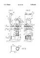
- FIG. 1is a locally cut away view in elevation of a water intake in accordance with the invention as seen in the direction of the arrow I in FIG. 3.
- FIG. 2is a side view of it as seen in the direction of the arrow II in FIG. 1.
- FIG. 3is a partial plan view of it on the line III--III in FIG. 1.
- the water intake 10is designed to be installed in any body of water 11. It comprises, assembled onto a common frame 12 and constituting therewith an integral and self-contained unit, a pump 13 adapted to be immersed in the water and a trash rake 14 for a grid 16 fitted to the suction side 18 of the pump 13 and/or a filter 19 on the discharge side 20 of the pump 13.
- the pump 13is disposed at the lower end of a hollow shaft 22 which is part of the frame 12.
- a filter 19is used, as in the embodiment shown, the upper end of the shaft 22 carries the filter 19 and the shaft provides a conduit between the pump 13 and the filter 19.
- the shaft 22is extended downwardly by an intake elbow bend 25 connected to it by a flange 26 and at the end of which is located the grid 16.
- the shaft 22is vertical and attached to a platform 28 which, like it, is part of the frame 12 and is intended to remain underwater.
- the shaft 22passes through the platform 28 and projects slightly above it.
- the filter 19is mounted directly to the end of the shaft 22.
- the filter 19includes a fixed screen 38 mounted off-center in a body 36 with a spiral-shape side wall.
- the filter 19has lifting rings 39 on the top.
- An evacuation pipe 40is connected to its outlet 35.
- the grid 16is a .grid made up of bars and is associated with a trash rake 14 diagrammatically represented in chain-dotted outline in FIG. 1.
- the uprights 43are attached to the intake elbow bend 25 and the grid 16 at their lower end. They are attached in the middle to the bottom of the platform 28 by triangular stiffener ribs 45 and to the top of the platform 28 by struts 46, if required.
- the platform 28carries a collection trough or basket 47 for collecting debris from the trash rake 14 and from the filter 19.
- Water drawn in by the pump 13enters through the grid as shown by the arrow F1 in FIG. 1.
- the screened waterexits the filter 19 as shown by the arrow F2 in FIG. 1.
- the hollow shaft 22supports the pump 13, provides a conduit between the latter and the filter 19 and supports the filter 19.
- the water intake in accordance with the inventionmay be totally immersed.
Landscapes
- Engineering & Computer Science (AREA)
- General Engineering & Computer Science (AREA)
- Mechanical Engineering (AREA)
- Civil Engineering (AREA)
- Structural Engineering (AREA)
- Structures Of Non-Positive Displacement Pumps (AREA)
- Details Of Reciprocating Pumps (AREA)
Abstract
Description
1. Field of the invention The present invention concerns water intakes and more particularly, but not exclusively, water intakes for industrial installations.
2.Description of the prior art
Water intakes of this kind are relatively complex screening and pumping stations which in their most complete form comprise a grid, usually made up of bars and with which is usually associated a trash rake, a filter, usually a chain or drum rotary filter, the ancillary units usually associated with a rotary filter of this kind and a pump which is usually an immersed vertical axis pump whose drive motor is usually above the water.
At present they are usually installed in a relatively large and deep masonry structure requiring relatively difficult civil engineering works because at least some of the works are executed below water level and in the underlying water table.
Although such civil engineering works are virtually unavoidable for water intakes capable of high unit flowrates, in the order of at least several cubic meters per second, for example, they would appear to be redundant and costly for smaller capacity water intakes.
A general object of the present invention is to provide a water intake Which gives satisfaction at reduced cost in such cases.
The present invention consists in a water intake comprising a common frame and assembled thereto and forming therewith an integral self-contained unit a pump adapted to be immersed and a trash rake and an associated grid on the suction side of said pump and/or a filter on the discharge side of said pump.
In a preferred embodiment of the invention, the pump may advantageously be disposed at the lower end of a hollow shaft which, if a filter is used, carries the filter at its upper end and provides a conduit between the pump and the filter.
A water intake in accordance with the invention constitutes a screening and pumping station as previously, although in a particularly compact form, and because it is self-contained it can advantageously be installed with no or with significantly reduced civil engineering works.
For example, it may easily be attached to a quay, at its edge, to a barge, to a wharf, to a mooring post or even to posts erected in the water.
The features and advantages of the present invention will emerge from the following description given by way of example only and with reference to the appended diagrammatic drawings.
FIG. 1 is a locally cut away view in elevation of a water intake in accordance with the invention as seen in the direction of the arrow I in FIG. 3.
FIG. 2 is a side view of it as seen in the direction of the arrow II in FIG. 1.
FIG. 3 is a partial plan view of it on the line III--III in FIG. 1.
Thewater intake 10 is designed to be installed in any body ofwater 11. It comprises, assembled onto acommon frame 12 and constituting therewith an integral and self-contained unit, apump 13 adapted to be immersed in the water and a trash rake 14 for agrid 16 fitted to thesuction side 18 of thepump 13 and/or afilter 19 on thedischarge side 20 of thepump 13.
Thepump 13 is disposed at the lower end of ahollow shaft 22 which is part of theframe 12. When afilter 19 is used, as in the embodiment shown, the upper end of theshaft 22 carries thefilter 19 and the shaft provides a conduit between thepump 13 and thefilter 19.
As thepump 13 is not in itself relevant to the present invention it will not be described here.
Suffice to say that it is an axial flow submersible pump, for example, slung from alifting ring 23 and lowered into theshaft 22 until it rests on an inside shoulder formed at its base by aflange 24 provided for this purpose. A lug projecting from the shoulder locates the pump in the angular direction relative to theshaft 22 and prevents it from rotating relative to the shaft.
Theshaft 22 is extended downwardly by anintake elbow bend 25 connected to it by aflange 26 and at the end of which is located thegrid 16.
Theshaft 22 is vertical and attached to aplatform 28 which, like it, is part of theframe 12 and is intended to remain underwater.
Theshaft 22 passes through theplatform 28 and projects slightly above it.
It is joined to theplatform 28 by a plurality oftriangular stiffener ribs 30 equi-angularly spaced below theplatform 28.
Thefilter 19 is mounted directly to the end of theshaft 22.
To this end it has at its inlet 32 aflange 33 by means of which it is attached to aflange 34 provided for this purpose at the upper end of theshaft 22.
As thefilter 19 is not in itself relevant to the present invention it will not be described in detail here.
Suffice to say that it is a filter with aside inlet 32 and anaxial outlet 35 of the type described in French patent 2 355 544, for example.
Thefilter 19 includes a fixedscreen 38 mounted off-center in abody 36 with a spiral-shape side wall.
Thefilter 19 haslifting rings 39 on the top.
Anevacuation pipe 40 is connected to itsoutlet 35.
Thegrid 16 is a .grid made up of bars and is associated with a trash rake 14 diagrammatically represented in chain-dotted outline in FIG. 1.
As the trash rake 14 is well known in itself and is not in itself relevant to the present invention it will not be described here.
Suffice to say that it is movable on twoparallel uprights 43 by awinch 41 driven by amotor 42. Theuprights 43 are attached to theintake elbow bend 25 and thegrid 16 at their lower end. They are attached in the middle to the bottom of theplatform 28 bytriangular stiffener ribs 45 and to the top of theplatform 28 bystruts 46, if required.
Theplatform 28 carries a collection trough orbasket 47 for collecting debris from the trash rake 14 and from thefilter 19.
Water drawn in by thepump 13 enters through the grid as shown by the arrow F1 in FIG. 1. The screened water exits thefilter 19 as shown by the arrow F2 in FIG. 1.
Thehollow shaft 22 supports thepump 13, provides a conduit between the latter and thefilter 19 and supports thefilter 19.
Of course, the present invention is not limited to the embodiment described and shown but encompasses any variant execution thereof.
In particular, apart from the motor driving the trash rake, if used, the water intake in accordance with the invention may be totally immersed.
Also, instead of being entirely vertical as specifically described and shown, it may be more or less inclined and/or articulated to enable it to be raised.
Furthermore, instead of being rigidly fastened to a fixed or floating support, it may be articulated to a support.
Claims (12)
1. A self-contained water intake assembly of unitary construction installable as a unit in a body of flowing water, said water intake assembly comprising a common frame including a substantially vertically hollow shaft, said hollow shaft having an upper and a lower end and defining a water flow conduit, an axial flow immersible pump unit mounted at the lower end of said shaft and housed substantially entirely therein for pumping water from the lower end to the upper end of said shaft, a self-cleaning filter mounted at and fluidly connected to the upper end of said shaft, an intake opening disposed at the lower end of said shaft upstream of said pump unit, a grid fitted within said intake opening, and a trash rake mounted on the common frame and extending parallel to said shaft, said trash rake engaging said grid, and said trash rake providing means for cleaning said grid.
2. Water intake assembly according to claim 1, wherein the immersible pump unit is entirely disposed within the conduit.
3. Water intake assembly according to claim 1, wherein said common frame comprises a platform, said hollow shaft being fixed to the platform.
4. Water intake assembly according to claim 3, wherein the conduit, platform and filter are entirely immersible.
5. Water intake assembly according to claim 3, wherein said hollow shaft passes through the platform.
6. Water intake assembly according to claim 5, wherein said platform is disposed at a level slightly above the surface of the body of water.
7. Water intake assembly according to claim 3, wherein said filter has a side inlet which is axially
8. Water intake assembly according to claim 7, wherein said conduit extends through the platform and the connection between the conduit and the filter is above the level of the platform.
9. Water intake assembly according to claim 7, wherein said conduit has an extension from the lower end, said extension defining the intake opening fitted with the grid.
10. Water intake assembly according to claim 9, wherein the extension comprises an intake elbow bend.
11. Water intake assembly according to claim 10, wherein the trash rake is carried by the platform.
12. Water intake assembly according to claim 11, further comprising a pair of uprights fixed to the platform and supporting said trash rake.
Applications Claiming Priority (2)
| Application Number | Priority Date | Filing Date | Title |
|---|---|---|---|
| FR9109372 | 1991-07-24 | ||
| FR9109372AFR2679575B1 (en) | 1991-07-24 | 1991-07-24 | WATER INTAKE, PARTICULARLY FOR INDUSTRIAL INSTALLATION. |
Publications (1)
| Publication Number | Publication Date |
|---|---|
| US5393418Atrue US5393418A (en) | 1995-02-28 |
Family
ID=9415491
Family Applications (1)
| Application Number | Title | Priority Date | Filing Date |
|---|---|---|---|
| US07/912,713Expired - Fee RelatedUS5393418A (en) | 1991-07-24 | 1992-07-13 | Water intake, in particular for industrial installations |
Country Status (6)
| Country | Link |
|---|---|
| US (1) | US5393418A (en) |
| EP (1) | EP0527075B1 (en) |
| JP (1) | JPH05187043A (en) |
| DE (1) | DE69200621T2 (en) |
| ES (1) | ES2065145T3 (en) |
| FR (1) | FR2679575B1 (en) |
Cited By (11)
| Publication number | Priority date | Publication date | Assignee | Title |
|---|---|---|---|---|
| AT410811B (en)* | 2000-07-14 | 2003-08-25 | Weiss Peter J Dipl Ing Dr | DEVICE FOR TAKING WASTE WATER FROM SURFACE WATERS |
| US20050115248A1 (en)* | 2003-10-29 | 2005-06-02 | Koehler Gregory J. | Liquefied natural gas structure |
| WO2005045143A3 (en)* | 2003-10-29 | 2005-09-15 | Shell Oil Co | Water intake systems for structures |
| US20060032798A1 (en)* | 2004-08-16 | 2006-02-16 | Laitram, L.L.C. | Water screen |
| US20060037897A1 (en)* | 2004-08-20 | 2006-02-23 | Philip Jackson | Water intake rotary screen |
| FR2892134A1 (en)* | 2005-10-14 | 2007-04-20 | Beaudrey Et Cie Sa E | Screening device for straining debris from a water course comprises a rotating screen in a tank with a grille in communication with the water course, and extractors positioned to return water to the water course |
| US20110030821A1 (en)* | 2009-08-07 | 2011-02-10 | Laxmikant Merchant | Apparatus and systems to control a fluid |
| US10781565B2 (en)* | 2018-06-02 | 2020-09-22 | Shenzhen Shenshui Water Resources Consulting Co., Ltd. | Water intake floating row cleaning system and construction method thereof |
| CN113350882A (en)* | 2021-05-31 | 2021-09-07 | 江苏运能能源科技有限公司 | Filter device for maintaining water taking |
| US11428219B2 (en)* | 2019-04-12 | 2022-08-30 | Cameron Farms Hutterite Colony | Liquid intake filters |
| US11795067B2 (en)* | 2016-06-07 | 2023-10-24 | Ide Water Technologies Ltd. | Environmentally friendly water intake and pretreatment system |
Families Citing this family (4)
| Publication number | Priority date | Publication date | Assignee | Title |
|---|---|---|---|---|
| DE19800005A1 (en)* | 1998-01-02 | 1999-07-08 | Linde Ag | Method and device for providing sea or sea water from great depths |
| RU2162920C2 (en)* | 1999-04-05 | 2001-02-10 | Курский государственный технический университет | Device for water intake from surface water reservoirs |
| RU2215095C2 (en)* | 2001-11-05 | 2003-10-27 | Курский государственный технический университет | Water intake device |
| CN104612112B (en)* | 2014-12-24 | 2016-07-20 | 中国水利水电第五工程局有限公司 | A kind of Water intake for water tower mouth fiaring cone formwork erecting structure |
Citations (33)
| Publication number | Priority date | Publication date | Assignee | Title |
|---|---|---|---|---|
| US857519A (en)* | 1906-10-17 | 1907-06-18 | William Stuart Foster | Strainer-support for water-pipes. |
| US1070788A (en)* | 1910-06-27 | 1913-08-19 | William S Elliott | Strainer system. |
| US1909578A (en)* | 1930-02-05 | 1933-05-16 | Octrooi Mij Hermes Nv | Pump |
| US1954824A (en)* | 1927-11-07 | 1934-04-17 | Menhorn Inc | Vacuum surrounded motor |
| US2045442A (en)* | 1935-03-19 | 1936-06-23 | Royden O Couch | Aerating device |
| US2106851A (en)* | 1936-07-02 | 1938-02-01 | Chicago Pump Co | Combined straining and comminuting apparatus |
| US2358841A (en)* | 1940-03-04 | 1944-09-26 | American Well Works | Sewage screening system |
| US2361231A (en)* | 1943-01-13 | 1944-10-24 | Nebolsine Ross | Apparatus for abstracting stream water |
| US2827268A (en)* | 1953-12-07 | 1958-03-18 | Staaf Gustaf Adolf | Liquid transporting apparatus |
| US2860835A (en)* | 1955-07-05 | 1958-11-18 | Passavant Werke | Tiltable underwater machine structure |
| DE973094C (en)* | 1950-10-31 | 1959-12-03 | Emu Unterwasserpumpen G M B H | Centrifugal pump |
| US3348686A (en)* | 1964-12-21 | 1967-10-24 | Carroll F Spitzer | Filter unit and vacuum attachment therefor |
| US3476038A (en)* | 1967-12-20 | 1969-11-04 | Layne & Bowler Pump Co | Suction pump vortex control |
| US3581903A (en)* | 1964-09-16 | 1971-06-01 | Finckh Metalltuch Maschf | Separator for paper pulp suspensions |
| US3735873A (en)* | 1969-06-10 | 1973-05-29 | Sunds Ab Sundsvall | Apparatus for screening aqueous suspensions, preferably fiber stock and/or fiber-pulp suspensions |
| FR2355544A1 (en)* | 1976-06-22 | 1978-01-20 | Beaudrey & Cie | FIXED STRAINER FILTER FOR INDUSTRIAL WATER |
| US4137177A (en)* | 1975-07-04 | 1979-01-30 | Nishihara Environmental Sanitation Research Corporation Limited | Filtering apparatus for sludgy liquids |
| US4392952A (en)* | 1981-04-20 | 1983-07-12 | Passavant-Werke Michelbacher Huette | Bar screen with screen cleaner for waste water treatment installations |
| FR2542042A1 (en)* | 1983-03-01 | 1984-09-07 | Terrier Andre | PROPELLER IMMERSION PUMP |
| US4618419A (en)* | 1984-07-19 | 1986-10-21 | Clive Hollinshead | Liquid storage tank moisture filter |
| US4622148A (en)* | 1985-06-25 | 1986-11-11 | Willinger Bros., Inc. | Aquarium filter system |
| US4713179A (en)* | 1986-03-14 | 1987-12-15 | Goedderz Sr Stanley J | Removable culvert grate |
| JPS63107714A (en)* | 1986-05-10 | 1988-05-12 | Kazuyoshi Ueichi | Purifying device in liquid tank |
| US4761226A (en)* | 1986-09-30 | 1988-08-02 | Henry Filters, Inc. | Continuously operable power actuated vacuum filter |
| US4779682A (en)* | 1985-06-12 | 1988-10-25 | Kabelwerk Eupen Ag | Method for the grit-free withdrawal of water from a well and also a device suitable therefor |
| FR2617912A1 (en)* | 1987-07-10 | 1989-01-13 | Terrier Andre | Water-pumping station |
| US4822486A (en)* | 1987-10-23 | 1989-04-18 | Perfection Sprinkler Co. | Rotary self-cleaning strainer |
| US4898513A (en)* | 1989-06-05 | 1990-02-06 | Mobil Oil Corp. | Circulating water system and sump pump strainer apparatus |
| US4966534A (en)* | 1989-05-02 | 1990-10-30 | Hasslen Iii John S | Sump draining apparatus |
| US4966532A (en)* | 1988-02-06 | 1990-10-30 | Lu Fengsheng | All dry submersible motor pump with a concordant seal system |
| US4981420A (en)* | 1988-06-11 | 1991-01-01 | Grundfos International A/S | Immersion pump |
| US5069796A (en)* | 1990-05-07 | 1991-12-03 | Fox James R | System for removing volatile components from water derived from wells |
| US5154588A (en)* | 1990-10-18 | 1992-10-13 | Oryz Energy Company | System for pumping fluids from horizontal wells |
- 1991
- 1991-07-24FRFR9109372Apatent/FR2679575B1/ennot_activeExpired - Fee Related
- 1992
- 1992-07-13USUS07/912,713patent/US5393418A/ennot_activeExpired - Fee Related
- 1992-07-23DEDE69200621Tpatent/DE69200621T2/ennot_activeRevoked
- 1992-07-23EPEP92402128Apatent/EP0527075B1/ennot_activeRevoked
- 1992-07-23ESES92402128Tpatent/ES2065145T3/ennot_activeExpired - Lifetime
- 1992-07-24JPJP4198358Apatent/JPH05187043A/enactivePending
Patent Citations (34)
| Publication number | Priority date | Publication date | Assignee | Title |
|---|---|---|---|---|
| US857519A (en)* | 1906-10-17 | 1907-06-18 | William Stuart Foster | Strainer-support for water-pipes. |
| US1070788A (en)* | 1910-06-27 | 1913-08-19 | William S Elliott | Strainer system. |
| US1954824A (en)* | 1927-11-07 | 1934-04-17 | Menhorn Inc | Vacuum surrounded motor |
| US1909578A (en)* | 1930-02-05 | 1933-05-16 | Octrooi Mij Hermes Nv | Pump |
| US2045442A (en)* | 1935-03-19 | 1936-06-23 | Royden O Couch | Aerating device |
| US2106851A (en)* | 1936-07-02 | 1938-02-01 | Chicago Pump Co | Combined straining and comminuting apparatus |
| US2358841A (en)* | 1940-03-04 | 1944-09-26 | American Well Works | Sewage screening system |
| US2361231A (en)* | 1943-01-13 | 1944-10-24 | Nebolsine Ross | Apparatus for abstracting stream water |
| DE973094C (en)* | 1950-10-31 | 1959-12-03 | Emu Unterwasserpumpen G M B H | Centrifugal pump |
| US2827268A (en)* | 1953-12-07 | 1958-03-18 | Staaf Gustaf Adolf | Liquid transporting apparatus |
| US2860835A (en)* | 1955-07-05 | 1958-11-18 | Passavant Werke | Tiltable underwater machine structure |
| US3581903A (en)* | 1964-09-16 | 1971-06-01 | Finckh Metalltuch Maschf | Separator for paper pulp suspensions |
| US3348686A (en)* | 1964-12-21 | 1967-10-24 | Carroll F Spitzer | Filter unit and vacuum attachment therefor |
| US3476038A (en)* | 1967-12-20 | 1969-11-04 | Layne & Bowler Pump Co | Suction pump vortex control |
| US3735873A (en)* | 1969-06-10 | 1973-05-29 | Sunds Ab Sundsvall | Apparatus for screening aqueous suspensions, preferably fiber stock and/or fiber-pulp suspensions |
| US4137177A (en)* | 1975-07-04 | 1979-01-30 | Nishihara Environmental Sanitation Research Corporation Limited | Filtering apparatus for sludgy liquids |
| US4276171A (en)* | 1976-06-22 | 1981-06-30 | E. Beaudrey & Cie | Water filter having spiral casing |
| FR2355544A1 (en)* | 1976-06-22 | 1978-01-20 | Beaudrey & Cie | FIXED STRAINER FILTER FOR INDUSTRIAL WATER |
| US4392952A (en)* | 1981-04-20 | 1983-07-12 | Passavant-Werke Michelbacher Huette | Bar screen with screen cleaner for waste water treatment installations |
| FR2542042A1 (en)* | 1983-03-01 | 1984-09-07 | Terrier Andre | PROPELLER IMMERSION PUMP |
| US4618419A (en)* | 1984-07-19 | 1986-10-21 | Clive Hollinshead | Liquid storage tank moisture filter |
| US4779682A (en)* | 1985-06-12 | 1988-10-25 | Kabelwerk Eupen Ag | Method for the grit-free withdrawal of water from a well and also a device suitable therefor |
| US4622148A (en)* | 1985-06-25 | 1986-11-11 | Willinger Bros., Inc. | Aquarium filter system |
| US4713179A (en)* | 1986-03-14 | 1987-12-15 | Goedderz Sr Stanley J | Removable culvert grate |
| JPS63107714A (en)* | 1986-05-10 | 1988-05-12 | Kazuyoshi Ueichi | Purifying device in liquid tank |
| US4761226A (en)* | 1986-09-30 | 1988-08-02 | Henry Filters, Inc. | Continuously operable power actuated vacuum filter |
| FR2617912A1 (en)* | 1987-07-10 | 1989-01-13 | Terrier Andre | Water-pumping station |
| US4822486A (en)* | 1987-10-23 | 1989-04-18 | Perfection Sprinkler Co. | Rotary self-cleaning strainer |
| US4966532A (en)* | 1988-02-06 | 1990-10-30 | Lu Fengsheng | All dry submersible motor pump with a concordant seal system |
| US4981420A (en)* | 1988-06-11 | 1991-01-01 | Grundfos International A/S | Immersion pump |
| US4966534A (en)* | 1989-05-02 | 1990-10-30 | Hasslen Iii John S | Sump draining apparatus |
| US4898513A (en)* | 1989-06-05 | 1990-02-06 | Mobil Oil Corp. | Circulating water system and sump pump strainer apparatus |
| US5069796A (en)* | 1990-05-07 | 1991-12-03 | Fox James R | System for removing volatile components from water derived from wells |
| US5154588A (en)* | 1990-10-18 | 1992-10-13 | Oryz Energy Company | System for pumping fluids from horizontal wells |
Cited By (14)
| Publication number | Priority date | Publication date | Assignee | Title |
|---|---|---|---|---|
| AT410811B (en)* | 2000-07-14 | 2003-08-25 | Weiss Peter J Dipl Ing Dr | DEVICE FOR TAKING WASTE WATER FROM SURFACE WATERS |
| US20050115248A1 (en)* | 2003-10-29 | 2005-06-02 | Koehler Gregory J. | Liquefied natural gas structure |
| WO2005045143A3 (en)* | 2003-10-29 | 2005-09-15 | Shell Oil Co | Water intake systems for structures |
| US20060032798A1 (en)* | 2004-08-16 | 2006-02-16 | Laitram, L.L.C. | Water screen |
| US7048850B2 (en) | 2004-08-16 | 2006-05-23 | Laitram, L.L.C. | Water screen |
| US7326336B2 (en)* | 2004-08-20 | 2008-02-05 | E. Beaudrey Et Cie | Water intake rotary screen |
| US20060037897A1 (en)* | 2004-08-20 | 2006-02-23 | Philip Jackson | Water intake rotary screen |
| FR2892134A1 (en)* | 2005-10-14 | 2007-04-20 | Beaudrey Et Cie Sa E | Screening device for straining debris from a water course comprises a rotating screen in a tank with a grille in communication with the water course, and extractors positioned to return water to the water course |
| US20110030821A1 (en)* | 2009-08-07 | 2011-02-10 | Laxmikant Merchant | Apparatus and systems to control a fluid |
| US8424566B2 (en) | 2009-08-07 | 2013-04-23 | General Electric Company | Apparatus and systems to control a fluid |
| US11795067B2 (en)* | 2016-06-07 | 2023-10-24 | Ide Water Technologies Ltd. | Environmentally friendly water intake and pretreatment system |
| US10781565B2 (en)* | 2018-06-02 | 2020-09-22 | Shenzhen Shenshui Water Resources Consulting Co., Ltd. | Water intake floating row cleaning system and construction method thereof |
| US11428219B2 (en)* | 2019-04-12 | 2022-08-30 | Cameron Farms Hutterite Colony | Liquid intake filters |
| CN113350882A (en)* | 2021-05-31 | 2021-09-07 | 江苏运能能源科技有限公司 | Filter device for maintaining water taking |
Also Published As
| Publication number | Publication date |
|---|---|
| FR2679575B1 (en) | 1993-11-05 |
| EP0527075A1 (en) | 1993-02-10 |
| DE69200621T2 (en) | 1995-03-09 |
| FR2679575A1 (en) | 1993-01-29 |
| ES2065145T3 (en) | 1995-02-01 |
| DE69200621D1 (en) | 1994-12-08 |
| JPH05187043A (en) | 1993-07-27 |
| EP0527075B1 (en) | 1994-11-02 |
Similar Documents
| Publication | Publication Date | Title |
|---|---|---|
| US5393418A (en) | Water intake, in particular for industrial installations | |
| JP2949517B2 (en) | Apparatus for recovering oil and fuel | |
| US3722689A (en) | Apparatus for extracting oil or the like from the surface of the sea | |
| CN207512873U (en) | A kind of rain dirt separator | |
| CN108252285A (en) | A kind of device for cleaning water surface rubbish and its application method | |
| JP2003205285A (en) | Facility for sedimentation resin | |
| CN220266711U (en) | Floating dock pump boat with filter cavity | |
| US5271832A (en) | Activation plant with funnel-shaped secondary sedimentation | |
| CN116201155A (en) | Water guide device for foundation pit construction | |
| CN214809133U (en) | Pump station for urban water supply and drainage | |
| CN210423060U (en) | Dredge pump convenient to dismantle | |
| CN210827793U (en) | Integrated pump station | |
| CN210371140U (en) | Prevent dredge pump of jam | |
| CN109806648B (en) | Sewage treatment device | |
| CN208716900U (en) | A kind of energy-saving oil separator | |
| CN216892325U (en) | Floating garbage collecting device for intercepting well | |
| CN108222107B (en) | Integral type desilting dewatering equipment | |
| CN214344684U (en) | Domestic water recycling device | |
| CN219517949U (en) | Drawing device for surface water of pool | |
| CN215367719U (en) | Prevent integration pump station sewage discharge groove of jam | |
| CN213836839U (en) | Rainwater is collected and is recycled device for landscape design | |
| JP3757291B2 (en) | Treatment pond | |
| CN219413054U (en) | Rainwater drainage pump | |
| JPH04190802A (en) | Oil-water separator | |
| CN219862905U (en) | Sump pit device of deep basal pit |
Legal Events
| Date | Code | Title | Description |
|---|---|---|---|
| AS | Assignment | Owner name:E. BEAUDREY & CIE A CORP. OF FRANCE, FRANCE Free format text:ASSIGNMENT OF ASSIGNORS INTEREST.;ASSIGNOR:JACKSON, PHILIP;REEL/FRAME:006193/0028 Effective date:19920615 | |
| FEPP | Fee payment procedure | Free format text:PAYOR NUMBER ASSIGNED (ORIGINAL EVENT CODE: ASPN); ENTITY STATUS OF PATENT OWNER: SMALL ENTITY | |
| FEPP | Fee payment procedure | Free format text:PAYOR NUMBER ASSIGNED (ORIGINAL EVENT CODE: ASPN); ENTITY STATUS OF PATENT OWNER: SMALL ENTITY Free format text:PAYER NUMBER DE-ASSIGNED (ORIGINAL EVENT CODE: RMPN); ENTITY STATUS OF PATENT OWNER: SMALL ENTITY | |
| FPAY | Fee payment | Year of fee payment:4 | |
| REMI | Maintenance fee reminder mailed | ||
| LAPS | Lapse for failure to pay maintenance fees | ||
| STCH | Information on status: patent discontinuation | Free format text:PATENT EXPIRED DUE TO NONPAYMENT OF MAINTENANCE FEES UNDER 37 CFR 1.362 | |
| FP | Lapsed due to failure to pay maintenance fee | Effective date:20030228 |