US5393129A - Electro-pneumatic freight brake control system - Google Patents
Electro-pneumatic freight brake control systemDownload PDFInfo
- Publication number
- US5393129A US5393129AUS08/209,893US20989394AUS5393129AUS 5393129 AUS5393129 AUS 5393129AUS 20989394 AUS20989394 AUS 20989394AUS 5393129 AUS5393129 AUS 5393129A
- Authority
- US
- United States
- Prior art keywords
- brake
- port
- pneumatic
- control
- electro
- Prior art date
- Legal status (The legal status is an assumption and is not a legal conclusion. Google has not performed a legal analysis and makes no representation as to the accuracy of the status listed.)
- Expired - Lifetime
Links
Images
Classifications
- B—PERFORMING OPERATIONS; TRANSPORTING
- B60—VEHICLES IN GENERAL
- B60T—VEHICLE BRAKE CONTROL SYSTEMS OR PARTS THEREOF; BRAKE CONTROL SYSTEMS OR PARTS THEREOF, IN GENERAL; ARRANGEMENT OF BRAKING ELEMENTS ON VEHICLES IN GENERAL; PORTABLE DEVICES FOR PREVENTING UNWANTED MOVEMENT OF VEHICLES; VEHICLE MODIFICATIONS TO FACILITATE COOLING OF BRAKES
- B60T17/00—Component parts, details, or accessories of power brake systems not covered by groups B60T8/00, B60T13/00 or B60T15/00, or presenting other characteristic features
- B60T17/18—Safety devices; Monitoring
- B60T17/22—Devices for monitoring or checking brake systems; Signal devices
- B60T17/228—Devices for monitoring or checking brake systems; Signal devices for railway vehicles
- B—PERFORMING OPERATIONS; TRANSPORTING
- B60—VEHICLES IN GENERAL
- B60T—VEHICLE BRAKE CONTROL SYSTEMS OR PARTS THEREOF; BRAKE CONTROL SYSTEMS OR PARTS THEREOF, IN GENERAL; ARRANGEMENT OF BRAKING ELEMENTS ON VEHICLES IN GENERAL; PORTABLE DEVICES FOR PREVENTING UNWANTED MOVEMENT OF VEHICLES; VEHICLE MODIFICATIONS TO FACILITATE COOLING OF BRAKES
- B60T13/00—Transmitting braking action from initiating means to ultimate brake actuator with power assistance or drive; Brake systems incorporating such transmitting means, e.g. air-pressure brake systems
- B60T13/10—Transmitting braking action from initiating means to ultimate brake actuator with power assistance or drive; Brake systems incorporating such transmitting means, e.g. air-pressure brake systems with fluid assistance, drive, or release
- B60T13/66—Electrical control in fluid-pressure brake systems
- B60T13/665—Electrical control in fluid-pressure brake systems the systems being specially adapted for transferring two or more command signals, e.g. railway systems
Definitions
- the present inventionrelates to a brake control system for railroad freight cars and in particular to such a brake control system that integrates electro-pneumatic control of the brake with the conventional automatic pneumatic brake control.
- Electro-pneumatic brake control systemsare known to extend the capability of the air brake beyond that which is achieved with the conventional automatic pneumatic brake control system presently employed. These improved capabilities are possible due primarily to the fact that the brake control signal can be transmitted instantaneously to each car in the train, whereas propagation of a pneumatic control signal is limited to a value approaching the speed of sound.
- instantaneously transmitting a brake control signal to each car of a trainnot only is the time required to initiate braking action on all of the cars reduced, but in-train forces, due to disproportionate brake buildup timing between the cars, are better controlled. This permits greater brake force to be employed to achieve shorter stop distance without incurring damage to car lading and couplers, and without creating the potential for a train derailment.
- the present automatic pneumatic brake control systemis fail-safe in the sense that a train break-in-two will result in an emergency brake application on both halves of the separated train without any initiative on the part of the locomotive engineer.
- Electro-pneumatic brakesalso offer the possibility of fail-safe operation. By appropriately configuring the electro-pneumatic valves in the brake cylinder and exhaust piping, brake pressure is obtained in a de-energized state.
- a fail-safe application of the electro-pneumatic brakesmay not be desirable, however, where loss of power to the electro-pneumatic valves results not from a train break-in-two, but from an electrical malfunction on an individual car, since the brakes on such an individual car would be applied while the train continued to run.
- the object of the present inventionis to provide an electro-pneumatic brake system that operates in conjunction with a back-up pneumatic brake system in such a manner that the back-up pneumatic brake will become effective to automatically override the electro-pneumatic brake when a loss of power occurs due to a train break-in-two without becoming effective when an individual car or cars experience a power loss.
- Still another object of the inventionis to provide an integrated pneumatic/electro-pneumatic brake control system that maintains the existing pneumatic brake functionality and compatibility when employed with a train having cars that may not be equipped with electro-pneumatic controlled brakes.
- a railroad freight caran integrated pneumatic/electro-pneumatic brake control system in which electro-pneumatic control means is arranged between a supply reservoir and the exhaust port of a conventional railroad car control valve device, which is normally stabilized in a release and charging position under control of brake pipe pressure that is normally maintained at the train running pressure to maintain the supply reservoir charged.
- electro-pneumatic control meansis arranged between a supply reservoir and the exhaust port of a conventional railroad car control valve device, which is normally stabilized in a release and charging position under control of brake pipe pressure that is normally maintained at the train running pressure to maintain the supply reservoir charged.
- a first fluid flow pathis established between the car brake cylinder device and the control valve exhaust port via which the electro-pneumatic control means is effective to regulate the brake cylinder pressure.
- the car control valve deviceIn the event of a train break-in-two, such that brake pipe pressure is depleted, the car control valve device is operated to an emergency position in which the aforementioned first flow path is interrupted and a second fluid flow path is established between the brake cylinder and the supply reservoir in bypass of the electro-pneumatic means to provide a back-up automatic pneumatic brake application.
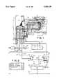
- FIG. 1is a partial diagrammatic view of a conventional pneumatic freight brake control valve device with which an electro-pneumatic brake control system shown in block diagram form is operatively combined;
- FIG. 2is a chart showing the status of the application and release magnet valves in different operating conditions of the electro-pneumatic brake system.
- FIG. 1there is shown a partial view of a conventional ABD, ABDW or ABDX type brake control valve device 14, such as may be employed on a railroad freight car.
- railroad freight carsinclude in addition to a brake pipe 1, a brake cylinder 3, an emergency reservoir 2, an auxiliary reservoir 5, and a retainer valve 10.
- the ends of brake pipe 1are provided with flexible hose and couplings (not shown) for connecting with the counterpart hose and couplings on adjacent ends of an adjoining freight car in a railroad train.
- brake pipe 1is charged with compressed air stored in the main reservoirs on the locomotive of the aforementioned railroad train, the pressure in brake pipe 1 being maintained at a predetermined running pressure when the locomotive brake valve (not shown) is set in release position.
- control valve device 14is set in its release and charging position, as shown, in response to the pressure in brake pipe 1 being increased, such as when charging the system and when releasing a previous brake application.
- compressed airis connected from brake pipe 1 to auxiliary reservoir 5 via branch pipe and port 1a, passage b, passage b2, a passage k in slide valve 13 of the service piston 11, a chamber Y under the service piston diaphragm, passage a1, passage a, and supply port and pipe 5a.
- compressed airis also connected from chamber Y to the emergency reservoir 2 via passage n in the service piston graduating valve 12, a passage m in slide valve 13, passages e4, e2, and supply port and pipe 2a.
- brake cylinder device 3Concurrently with the aforementioned charging, brake cylinder device 3 is vented to atmosphere via pipe and delivery port 3a, passages c, c1, slot t in slide valve 13, passage ex, port and pipe 10a, and a pressure retainer valve 10.
- the foregoing pneumatic brake control systemis capable of providing service and emergency brake applications in accordance with a reduction in brake pipe pressure at appropriate rates in a well-known manner.
- an electro-pneumatic brake control systemincluding a microprocessor unit 20, an application magnet valve 22 and a release magnet valve 24.
- These magnet valves 22, 24are solenoid operated, spring returned, 3-way, pneumatic valves, the respective solenoid operators being connected by wires 26, 28 to microprocessor unit 20.
- Each magnet valvehas an inlet 30 and a pair of outlets 32, 34, inlet 30 of magnet valve 22 being connected to exhaust pipe 10a, and outlet port 32 of magnet valve 24 being connected to emergency reservoir 2 via a pipe 38 and pipe 2a.
- a pipe 10bis connected between outlet 34 of magnet valve 22 and inlet 30 of magnet valve 24.
- Outlet 32 of magnet valve 22is blanked, while outlet 34 of magnet valve 24 is connected to retainer valve 10 via pipe 10c.
- Electrical power for the microprocessor unit 20 and the solenoid operators of the respective magnet valvesmay be provided by an on-car battery 42, while a control wire 44, that is interconnected by suitable connectors (not shown) to a corresponding control wire of an adjoining car (not shown) forms a train line to conduct brake control signals from the locomotive to microprocessor unit 20.
- a control wire 44that is interconnected by suitable connectors (not shown) to a corresponding control wire of an adjoining car (not shown) forms a train line to conduct brake control signals from the locomotive to microprocessor unit 20.
- a pressure transducer 46Connected via a pipe 3b to brake cylinder pipe 3a is a pressure transducer 46 that provides feedback information corresponding to the instantaneous brake cylinder pressure to the microprocessor unit via wire 48.
- a pressure relief valve 50Also connected to brake cylinder pipe 3a via a pipe 3c is a pressure relief valve 50.
- the brake cylinder pressureis under control of the magnet valves 22, 24, which are shown in a de-energized condition consistent with the absence of a signal at control wire 44 during the above explained charging of the pneumatic brake system, as can be seen from the chart of FIG. 2.
- Thisaccommodates venting of brake cylinder 3 during charging of the pneumatic brake system, via the car retainer valve 10. Since control valve device 14 is in release and charging position, as shown and described in response to charging of brake pipe 1, slide valve 13 is positioned by service piston 11 such that slot t connects passages ex and c1 to establish an exhaust path through control valve device 14. Accordingly, brake cylinder 3 is vented to atmosphere via pipe and port 3a, the aforementioned exhaust path including passages c, c1, slot t, passage ex, port and pipe 10a, and interconnected ports 30, 34 of magnet valve 24.
- a control signalis conducted over wire 44, which is evaluated by microprocessor unit 20 in terms of the brake cylinder pressure feedback signal received via wire 48. Since brake cylinder pressure is exhausted due to the venting thereof during charging, as above-mentioned, a difference exists between the control and feedback signals indicative of the desired level of brake application. Microprocessor unit 20 responds to this signal difference to energize magnet valve 24 and maintain magnet valve 22 de-energized, as shown in the chart of FIG. 2 for an application condition. Inlet port 30 of magnet valve 24 is thus cut off from the vent connection at port 34 and is instead connected to outlet port 32.
- Emergency reservoir pressureis thus connected to brake cylinder 3 via pipes 2a and 38, release magnet valve 24, pipe 10b, application magnet valve 22, exhaust pipe and port 10a, the control valve exhaust path including passage ex, slot t in service piston slide valve 13, and passages c1 and c, and port and pipe 3a.
- the brake cylinder pressuremay be released in graduated increments by reducing the control wire signal accordingly.
- microprocessor unit 20operates to de-energize both magnet valves 22 and 24.
- the brake cylinder pressureis released to atmosphere via retainer valve 10. If only a partial release is desired, the control wire signal is only partially reduced to allow the brake cylinder pressure feedback signal to drop below the control wire signal and thereby cause microprocessor 20 to terminate the venting of brake cylinder pressure by establishing a lap condition of the magnet valves 22 and 24.
- brake pipe 1will continue to be maintained at its predetermined running pressure, and control valve device 14 will accordingly remain in release and charging position to maintain the pressure in auxiliary reservoir 5 and emergency reservoir 2 charged to the predetermined running pressure established in brake pipe 1. In this manner, continued graduated releases and re-application of the brakes can be made without exhausting the supply of compressed air stored in emergency reservoir 2.
- both magnet valveswill automatically revert to a de-energized condition, thereby effecting a release of any brake application that might exist at the time.
- a condition of power failurewould of course only occur on an individual car basis, as opposed to the entire train of cars, the percentage of brake reduction would be relatively inconsequential in terms of a train of cars.
- control valve device 1responds to the resultant reduction of brake pipe pressure to effect an emergency brake application, which will be propagated through all of the cars in both halves of the separated train to bring the train to a safe stop.
- brake cylinder pressure under control of control valve device 14occurs irrespective of the fact that the magnet valves 22 and 24 are arranged to fail to a release condition, as explained. This is possible since in application position, control valve device 14 interrupts the aforementioned vent path to which application and release magnet valves 22 and 24 are connected in the shown release and charging position of control valve device 14.
- the pressure in emergency reservoir 2is also connected to brake cylinder 3 through the high pressure valve in the control valve emergency portion (not shown), and passage c to provide an additional source of compressed air, which, combined with the compressed air provided by auxiliary reservoir 5, establishes a higher emergency brake pressure than is obtained during a full service application, in accordance with the conventional, well-known operation of ABD, ABDW and ABDX type control valves.
- Pressure relief valve 50is provided to prevent an over-charge condition of brake cylinder 3 from developing when making an emergency on top of an electro-pneumatic application, since any air taken out of emergency reservoir to supply the brake cylinder during an electro-pneumatic application is continually replenished so that full emergency reservoir pressure, as well as auxiliary reservoir pressure is always available regardless of the existing brake cylinder pressure.
- control signal transmitted via control were 44is regulated to cause microprocessor 20 to maintain magnet valves 22, 24 deenergized. This establishes the normal venting of exhaust pipe 10a via magnet valves 22, 24 and retainer valve 10. Consequently, brake cylinder pressure may be applied and released under brake pipe control in the usual, well-known manner, with retainer valve 10 being available to provide grade bake control.
Landscapes
- Engineering & Computer Science (AREA)
- Transportation (AREA)
- Mechanical Engineering (AREA)
- Braking Systems And Boosters (AREA)
Abstract
Description
Claims (10)
Priority Applications (6)
| Application Number | Priority Date | Filing Date | Title |
|---|---|---|---|
| US08/209,893US5393129A (en) | 1994-03-14 | 1994-03-14 | Electro-pneumatic freight brake control system |
| CA002123040ACA2123040C (en) | 1994-03-14 | 1994-05-06 | Electro-pneumatic freight brake control system |
| AU61998/94AAU663443B1 (en) | 1994-03-14 | 1994-05-09 | Electro-pneumatic freight brake control system |
| ZA944300AZA944300B (en) | 1994-03-14 | 1994-06-16 | Electro-pneumatic freight brake control system |
| BR9403705ABR9403705A (en) | 1994-03-14 | 1994-10-13 | Braking control device |
| JP7054180AJP2753457B2 (en) | 1994-03-14 | 1995-03-14 | Pneumatic / electro-pneumatic brake control device for railway vehicles |
Applications Claiming Priority (1)
| Application Number | Priority Date | Filing Date | Title |
|---|---|---|---|
| US08/209,893US5393129A (en) | 1994-03-14 | 1994-03-14 | Electro-pneumatic freight brake control system |
Publications (1)
| Publication Number | Publication Date |
|---|---|
| US5393129Atrue US5393129A (en) | 1995-02-28 |
Family
ID=22780747
Family Applications (1)
| Application Number | Title | Priority Date | Filing Date |
|---|---|---|---|
| US08/209,893Expired - LifetimeUS5393129A (en) | 1994-03-14 | 1994-03-14 | Electro-pneumatic freight brake control system |
Country Status (6)
| Country | Link |
|---|---|
| US (1) | US5393129A (en) |
| JP (1) | JP2753457B2 (en) |
| AU (1) | AU663443B1 (en) |
| BR (1) | BR9403705A (en) |
| CA (1) | CA2123040C (en) |
| ZA (1) | ZA944300B (en) |
Cited By (31)
| Publication number | Priority date | Publication date | Assignee | Title |
|---|---|---|---|---|
| US5501512A (en)* | 1995-06-27 | 1996-03-26 | Westinghouse Air Brake Company | System and method for automatically calibrating transducers in electro-pneumatic freight brake control systems |
| US5503467A (en)* | 1995-05-23 | 1996-04-02 | Westinghouse Air Brake Company | Pneumatic emergency backup for electro-pneumatic freight brake |
| US5603556A (en)* | 1995-11-20 | 1997-02-18 | Technical Services And Marketing, Inc. | Rail car load sensor |
| US5616965A (en)* | 1994-05-24 | 1997-04-01 | Woco Franz-Josef Wolf & Co. | Electro-pneumatic bus |
| US5622338A (en)* | 1996-07-02 | 1997-04-22 | Technical Services And Marketing Inc. | Truck hunting detection and abatement apparatus using selective brake application |
| US5676431A (en)* | 1995-09-06 | 1997-10-14 | New York Air Brake Corporation | Electropneumatic pilot adapter |
| US5722736A (en)* | 1995-11-30 | 1998-03-03 | Zeftron, Inc. | Electronic pneumatic brake system |
| WO1998009857A1 (en)* | 1996-09-06 | 1998-03-12 | New York Air Brake Corporation | Electropneumatic brake control valve |
| US5730504A (en)* | 1997-01-14 | 1998-03-24 | Westinghouse Air Brake Company | Release assuring arrangement for combined electro-pneumatic/automatic pneumatic brake |
| US5746484A (en)* | 1996-08-09 | 1998-05-05 | Westinghouse Air Brake Company | E/P interface with pneumatic control valve for back-up brake arrangement |
| US5813730A (en)* | 1996-11-26 | 1998-09-29 | Technical Services And Marketing, Inc. | Retrofit air distribution apparatus for a locomotive braking system |
| US5862048A (en)* | 1994-10-05 | 1999-01-19 | New York Air Brake Corporation | Microprocessor based electro-pneumatic locomotive brake control and train monitoring system |
| US5924774A (en)* | 1995-11-30 | 1999-07-20 | Zeftron, Inc. | Electronic pneumatic brake system |
| US5944391A (en)* | 1997-03-25 | 1999-08-31 | Pulse Electronics, Inc. | Electronic fail safe circuit for electro-pneumatic brake control |
| US6017098A (en)* | 1998-03-10 | 2000-01-25 | Westinghouse Air Brake Company | Brake pipe control portion to enhance operation under low main reservoir pressure conditions |
| US6050650A (en)* | 1998-07-09 | 2000-04-18 | Westinghouse Air Brake Company | Application solenoid valve for electronically controlled freight train brake system |
| US6095618A (en)* | 1998-03-19 | 2000-08-01 | Ge-Harris Railway Electronics, L.L.C. | Segmented brake pipe train control system and related methods |
| US6179391B1 (en) | 1999-02-01 | 2001-01-30 | Allliedsignal Truck Brake Systems Company | Relay valve with integral biased double check valve |
| EP0894688A3 (en)* | 1997-07-31 | 2001-02-28 | Westinghouse Air Brake Company | Apparatus and method for a railway freight car brake control |
| EP0856448A3 (en)* | 1997-01-29 | 2001-03-28 | Westinghouse Air Brake Company | Brake pipe sensing unit cross-reference to related applications |
| US6353780B1 (en) | 1999-06-29 | 2002-03-05 | Westinghouse Air Brake Technologies Corporation | Grade speed control and method for railway freight vehicle |
| US6587764B2 (en) | 1997-09-12 | 2003-07-01 | New York Air Brake Corporation | Method of optimizing train operation and training |
| US6609769B2 (en) | 2000-06-28 | 2003-08-26 | Westinghouse Air Brake Technologies Corporation | Apparatus and method for pneumatically controlled graduated brake pressure release for freight train brake system |
| US6648422B2 (en)* | 1996-09-13 | 2003-11-18 | New York Air Brake Corporation | Integrated train electrical and pneumatic brakes |
| US6932437B1 (en)* | 1996-09-13 | 2005-08-23 | New York Air Brake Corporation | Integrated train electrical and pneumatic brakes |
| US20060138856A1 (en)* | 2004-12-27 | 2006-06-29 | New York Air Brake Corporation | Relay configuration for an electro-pneumatic train |
| US20070236077A1 (en)* | 2006-03-28 | 2007-10-11 | Wabtec Holding Corporation | Pneumatic emergency brake release timer |
| US20140097667A1 (en)* | 2012-10-10 | 2014-04-10 | General Electric Company | Systems and methods for vehicle braking control |
| US10994756B2 (en) | 2017-11-16 | 2021-05-04 | Westinghouse Air Brake Technologies Corporation | Electronically controlled brake overlay system for distributor valve |
| US11014585B2 (en) | 2017-11-16 | 2021-05-25 | Westinghouse Air Brake Technologies Corporation | ECP overlay system for W-type triple valve |
| US11027756B2 (en) | 2017-11-16 | 2021-06-08 | Westinghouse Air Brake Technologies Corporation | ECP overlay system for UIC-type distributor valve |
Citations (8)
| Publication number | Priority date | Publication date | Assignee | Title |
|---|---|---|---|---|
| US4344138A (en)* | 1980-11-05 | 1982-08-10 | Frasier Cline W | Digital air brake control system |
| US4904027A (en)* | 1988-10-03 | 1990-02-27 | American Standard Inc. | Digital air brake control system |
| US4978179A (en)* | 1989-05-22 | 1990-12-18 | American Standard Inc. | Brake assurance circuit operative in response to a low brake pipe pressure |
| US5020862A (en)* | 1989-09-27 | 1991-06-04 | American Standard Inc. | Penalty brake control system |
| US5064251A (en)* | 1990-04-02 | 1991-11-12 | Westinghouse Air Brake Company | Electropneumatic air brake control system for railway vehicles |
| US5090780A (en)* | 1991-05-03 | 1992-02-25 | Westinghouse Air Brake Company | Binary weighted digital flow regulating system |
| US5222788A (en)* | 1991-09-16 | 1993-06-29 | Westinghouse Air Brake Company | Microprocessor based electro-pneumatic locomotive brake control system having brake assurance circuit |
| US5286096A (en)* | 1992-08-13 | 1994-02-15 | Westinghouse Air Brake Company | Arrangement for enhancing the bail-off function of brake cylinder pressures on a railroad locomotive |
Family Cites Families (2)
| Publication number | Priority date | Publication date | Assignee | Title |
|---|---|---|---|---|
| US5090760A (en)* | 1990-01-29 | 1992-02-25 | Wheeler Basil W | Break-away gas fill guard |
| US5222786A (en)* | 1992-01-10 | 1993-06-29 | Royal Appliance Mfg. Co. | Wheel construction for vacuum cleaner |
- 1994
- 1994-03-14USUS08/209,893patent/US5393129A/ennot_activeExpired - Lifetime
- 1994-05-06CACA002123040Apatent/CA2123040C/ennot_activeExpired - Fee Related
- 1994-05-09AUAU61998/94Apatent/AU663443B1/ennot_activeCeased
- 1994-06-16ZAZA944300Apatent/ZA944300B/enunknown
- 1994-10-13BRBR9403705Apatent/BR9403705A/ennot_activeIP Right Cessation
- 1995
- 1995-03-14JPJP7054180Apatent/JP2753457B2/ennot_activeExpired - Fee Related
Patent Citations (8)
| Publication number | Priority date | Publication date | Assignee | Title |
|---|---|---|---|---|
| US4344138A (en)* | 1980-11-05 | 1982-08-10 | Frasier Cline W | Digital air brake control system |
| US4904027A (en)* | 1988-10-03 | 1990-02-27 | American Standard Inc. | Digital air brake control system |
| US4978179A (en)* | 1989-05-22 | 1990-12-18 | American Standard Inc. | Brake assurance circuit operative in response to a low brake pipe pressure |
| US5020862A (en)* | 1989-09-27 | 1991-06-04 | American Standard Inc. | Penalty brake control system |
| US5064251A (en)* | 1990-04-02 | 1991-11-12 | Westinghouse Air Brake Company | Electropneumatic air brake control system for railway vehicles |
| US5090780A (en)* | 1991-05-03 | 1992-02-25 | Westinghouse Air Brake Company | Binary weighted digital flow regulating system |
| US5222788A (en)* | 1991-09-16 | 1993-06-29 | Westinghouse Air Brake Company | Microprocessor based electro-pneumatic locomotive brake control system having brake assurance circuit |
| US5286096A (en)* | 1992-08-13 | 1994-02-15 | Westinghouse Air Brake Company | Arrangement for enhancing the bail-off function of brake cylinder pressures on a railroad locomotive |
Non-Patent Citations (2)
| Title |
|---|
| DeLeon et al., Electro Pneumatic Brakes and Other Concepts Being Developed at the University of New Hampshire, Aug. 1992.* |
| DeLeon et al., Electro-Pneumatic Brakes and Other Concepts Being Developed at the University of New Hampshire, Aug. 1992. |
Cited By (50)
| Publication number | Priority date | Publication date | Assignee | Title |
|---|---|---|---|---|
| US5616965A (en)* | 1994-05-24 | 1997-04-01 | Woco Franz-Josef Wolf & Co. | Electro-pneumatic bus |
| US5862048A (en)* | 1994-10-05 | 1999-01-19 | New York Air Brake Corporation | Microprocessor based electro-pneumatic locomotive brake control and train monitoring system |
| US5503467A (en)* | 1995-05-23 | 1996-04-02 | Westinghouse Air Brake Company | Pneumatic emergency backup for electro-pneumatic freight brake |
| AU699508B2 (en)* | 1995-05-23 | 1998-12-03 | Westinghouse Air Brake Company | Pneumatic emergency backup for electro-pneumatic freight brake |
| US5501512A (en)* | 1995-06-27 | 1996-03-26 | Westinghouse Air Brake Company | System and method for automatically calibrating transducers in electro-pneumatic freight brake control systems |
| US5676431A (en)* | 1995-09-06 | 1997-10-14 | New York Air Brake Corporation | Electropneumatic pilot adapter |
| WO1997018979A1 (en)* | 1995-11-20 | 1997-05-29 | Technical Services And Marketing, Inc. | Rail car load sensor |
| AU699524B2 (en)* | 1995-11-20 | 1998-12-03 | Westinghouse Air Brake Technologies Corporation | Rail car load sensor |
| US5603556A (en)* | 1995-11-20 | 1997-02-18 | Technical Services And Marketing, Inc. | Rail car load sensor |
| US5735580A (en)* | 1995-11-20 | 1998-04-07 | Technical Services And Marketing Inc. | Rail car load sensor |
| US5722736A (en)* | 1995-11-30 | 1998-03-03 | Zeftron, Inc. | Electronic pneumatic brake system |
| US5924774A (en)* | 1995-11-30 | 1999-07-20 | Zeftron, Inc. | Electronic pneumatic brake system |
| US5622338A (en)* | 1996-07-02 | 1997-04-22 | Technical Services And Marketing Inc. | Truck hunting detection and abatement apparatus using selective brake application |
| US5746484A (en)* | 1996-08-09 | 1998-05-05 | Westinghouse Air Brake Company | E/P interface with pneumatic control valve for back-up brake arrangement |
| AU717313B2 (en)* | 1996-09-06 | 2000-03-23 | New York Air Brake Llc | Electropneumatic brake control valve |
| US6457782B1 (en) | 1996-09-06 | 2002-10-01 | New York Air Brake Corporation | Electropneumatic brake control valve |
| WO1998009857A1 (en)* | 1996-09-06 | 1998-03-12 | New York Air Brake Corporation | Electropneumatic brake control valve |
| AU717313C (en)* | 1996-09-06 | 2001-12-06 | New York Air Brake Llc | Electropneumatic brake control valve |
| US5967620A (en)* | 1996-09-06 | 1999-10-19 | New York Air Brake Corporation | Electropneumatic brake control valve |
| US6325464B2 (en) | 1996-09-06 | 2001-12-04 | New York Air Brake Corporation | Electropneumatic brake control valve |
| US20040090111A1 (en)* | 1996-09-13 | 2004-05-13 | New York Air Brake Corporation | Integrated train electrical and pneumatic brakes |
| US6648422B2 (en)* | 1996-09-13 | 2003-11-18 | New York Air Brake Corporation | Integrated train electrical and pneumatic brakes |
| US7029076B2 (en) | 1996-09-13 | 2006-04-18 | New York Air Brake Corporation | Integrated train electrical and pneumatic brakes |
| US7004550B2 (en) | 1996-09-13 | 2006-02-28 | New York Air Brake Corporation | Integrated train electrical and pneumatic brakes |
| US6932437B1 (en)* | 1996-09-13 | 2005-08-23 | New York Air Brake Corporation | Integrated train electrical and pneumatic brakes |
| AU715160B2 (en)* | 1996-11-26 | 2000-01-20 | Westinghouse Air Brake Technologies Corporation | Retrofit air distribution apparatus for a locomotive braking system |
| US5813730A (en)* | 1996-11-26 | 1998-09-29 | Technical Services And Marketing, Inc. | Retrofit air distribution apparatus for a locomotive braking system |
| AU730164B2 (en)* | 1997-01-14 | 2001-03-01 | Westinghouse Air Brake Company | Release assuring arrangement for combined electro-pneumatic/automatic pneumatic brake |
| US5730504A (en)* | 1997-01-14 | 1998-03-24 | Westinghouse Air Brake Company | Release assuring arrangement for combined electro-pneumatic/automatic pneumatic brake |
| EP0856448A3 (en)* | 1997-01-29 | 2001-03-28 | Westinghouse Air Brake Company | Brake pipe sensing unit cross-reference to related applications |
| US5944391A (en)* | 1997-03-25 | 1999-08-31 | Pulse Electronics, Inc. | Electronic fail safe circuit for electro-pneumatic brake control |
| EP0894688A3 (en)* | 1997-07-31 | 2001-02-28 | Westinghouse Air Brake Company | Apparatus and method for a railway freight car brake control |
| US6587764B2 (en) | 1997-09-12 | 2003-07-01 | New York Air Brake Corporation | Method of optimizing train operation and training |
| US6017098A (en)* | 1998-03-10 | 2000-01-25 | Westinghouse Air Brake Company | Brake pipe control portion to enhance operation under low main reservoir pressure conditions |
| AU741751B2 (en)* | 1998-03-10 | 2001-12-06 | Westinghouse Air Brake Company | Improvement to brake pipe control portion to enhance operation under low main reservoir pressure conditions |
| US6095618A (en)* | 1998-03-19 | 2000-08-01 | Ge-Harris Railway Electronics, L.L.C. | Segmented brake pipe train control system and related methods |
| US6050650A (en)* | 1998-07-09 | 2000-04-18 | Westinghouse Air Brake Company | Application solenoid valve for electronically controlled freight train brake system |
| US6179391B1 (en) | 1999-02-01 | 2001-01-30 | Allliedsignal Truck Brake Systems Company | Relay valve with integral biased double check valve |
| US6353780B1 (en) | 1999-06-29 | 2002-03-05 | Westinghouse Air Brake Technologies Corporation | Grade speed control and method for railway freight vehicle |
| US7306294B2 (en) | 2000-06-28 | 2007-12-11 | Westinghouse Air Brake Technologies Corporation | Apparatus and method for pneumatically controlled graduated brake pressure release for freight train brake system |
| US6609769B2 (en) | 2000-06-28 | 2003-08-26 | Westinghouse Air Brake Technologies Corporation | Apparatus and method for pneumatically controlled graduated brake pressure release for freight train brake system |
| US20060138856A1 (en)* | 2004-12-27 | 2006-06-29 | New York Air Brake Corporation | Relay configuration for an electro-pneumatic train |
| US7350878B2 (en) | 2004-12-27 | 2008-04-01 | New York Air Brake Corporation | Relay configuration for an electro-pneumatic train |
| US20070236077A1 (en)* | 2006-03-28 | 2007-10-11 | Wabtec Holding Corporation | Pneumatic emergency brake release timer |
| US7520574B2 (en) | 2006-03-28 | 2009-04-21 | Wabtec Holding Corporation | Pneumatic emergency brake release timer |
| US20140097667A1 (en)* | 2012-10-10 | 2014-04-10 | General Electric Company | Systems and methods for vehicle braking control |
| US9889829B2 (en)* | 2012-10-10 | 2018-02-13 | Alstom Transport Technologies | Systems and methods for vehicle braking control |
| US10994756B2 (en) | 2017-11-16 | 2021-05-04 | Westinghouse Air Brake Technologies Corporation | Electronically controlled brake overlay system for distributor valve |
| US11014585B2 (en) | 2017-11-16 | 2021-05-25 | Westinghouse Air Brake Technologies Corporation | ECP overlay system for W-type triple valve |
| US11027756B2 (en) | 2017-11-16 | 2021-06-08 | Westinghouse Air Brake Technologies Corporation | ECP overlay system for UIC-type distributor valve |
Also Published As
| Publication number | Publication date |
|---|---|
| CA2123040C (en) | 1998-06-16 |
| JP2753457B2 (en) | 1998-05-20 |
| BR9403705A (en) | 1995-10-24 |
| AU663443B1 (en) | 1995-10-05 |
| CA2123040A1 (en) | 1995-09-15 |
| ZA944300B (en) | 1995-05-08 |
| JPH07257360A (en) | 1995-10-09 |
Similar Documents
| Publication | Publication Date | Title |
|---|---|---|
| US5393129A (en) | Electro-pneumatic freight brake control system | |
| US5746484A (en) | E/P interface with pneumatic control valve for back-up brake arrangement | |
| CA2351915C (en) | Apparatus and method for pneumatically controlled graduated brake pressure release for freight train brake system | |
| US5222788A (en) | Microprocessor based electro-pneumatic locomotive brake control system having brake assurance circuit | |
| US4598953A (en) | Electropneumatic brake control system for railway transit vehicle | |
| US5192118A (en) | Electro-pneumatic locomotive brake control system | |
| US5494342A (en) | Electropneumatic brake control system | |
| US5503467A (en) | Pneumatic emergency backup for electro-pneumatic freight brake | |
| US5332297A (en) | Charging cut-off valve arrangement for microprocessor-based electropneumatic locomotive brake control system | |
| CA2145381C (en) | Apparatus to prevent inadvertent discharge and trapping of pipe pressure in an electro-pneumatic locomotive brake control system | |
| US5730504A (en) | Release assuring arrangement for combined electro-pneumatic/automatic pneumatic brake | |
| CA2174910C (en) | Pneumatic empty/load proportioning for electro-pneumatic brake | |
| US6375277B1 (en) | Manual release valve apparatus for ECP brake equipment | |
| JP3430164B2 (en) | Vent valve inserts and shut-off vent valve inserts and filled vent valve inserts | |
| CN106660536A (en) | Compressed air unit for vehicles with integrated emergency air supply pressure vessel | |
| CA2343605C (en) | Ecp manifold vent valve insert | |
| US6347840B1 (en) | ECP commanded emergencies via a conventional EAB brake controller | |
| US4971399A (en) | System for assuring recharge of brake pipe pressure in holding position of locomotive brake valve | |
| US6746087B1 (en) | Electronic equalizing reservoir controller with pneumatic penalty override | |
| US5429424A (en) | Pneumatic brake for railway locomotives and motor cars | |
| EP1273498B1 (en) | Apparatus and method for pneumatically controlled graduated brake pressure release for freight train brake system | |
| US3525556A (en) | Fluid pressure brake apparatus for remote multiple unit locomotive trains | |
| CA2558723C (en) | Apparatus and method for pneumatically controlled graduated brake pressure release for freight train brake system | |
| US2860928A (en) | Fluid pressure brake apparatus with means for preventing improper suppression of automatic train control | |
| US2723884A (en) | Fluid pressure and dynamic brake interlock apparatus |
Legal Events
| Date | Code | Title | Description |
|---|---|---|---|
| AS | Assignment | Owner name:WESTINGHOUSE AIR BRAKE COMPANY, PENNSYLVANIA Free format text:ASSIGNMENT OF ASSIGNORS INTEREST;ASSIGNORS:TROIANI, VINCENT F.;GAUGHAN, EDWARD W.;REEL/FRAME:006913/0164 Effective date:19940309 | |
| STCF | Information on status: patent grant | Free format text:PATENTED CASE | |
| AS | Assignment | Owner name:CHASE MANHATTAN BANK, THE, NEW YORK Free format text:SECURITY INTEREST;ASSIGNOR:WESTINGHOUSE AIR BRAKE COMPANY;REEL/FRAME:009423/0239 Effective date:19980630 | |
| FPAY | Fee payment | Year of fee payment:4 | |
| FEPP | Fee payment procedure | Free format text:PAYOR NUMBER ASSIGNED (ORIGINAL EVENT CODE: ASPN); ENTITY STATUS OF PATENT OWNER: LARGE ENTITY | |
| AS | Assignment | Owner name:WESTINGHOUSE AIR BRAKE COMPANY, PENNSYLVANIA Free format text:TERMINATION OF SECURITY INTEREST RECORDAL STARTING AT REEL/FRAME 9423/0239.;ASSIGNOR:CHASE MANHATTAN BANK, AS COLLATERAL AGENT, THE;REEL/FRAME:012280/0283 Effective date:20010501 | |
| FPAY | Fee payment | Year of fee payment:8 | |
| REMI | Maintenance fee reminder mailed | ||
| FPAY | Fee payment | Year of fee payment:12 |