US5392790A - Instrument for obtaining bore type tissue sampling - Google Patents
Instrument for obtaining bore type tissue samplingDownload PDFInfo
- Publication number
- US5392790A US5392790AUS08/056,256US5625693AUS5392790AUS 5392790 AUS5392790 AUS 5392790AUS 5625693 AUS5625693 AUS 5625693AUS 5392790 AUS5392790 AUS 5392790A
- Authority
- US
- United States
- Prior art keywords
- cylinder
- instrument according
- instrument
- chamber
- piston
- Prior art date
- Legal status (The legal status is an assumption and is not a legal conclusion. Google has not performed a legal analysis and makes no representation as to the accuracy of the status listed.)
- Expired - Fee Related
Links
- 238000005070samplingMethods0.000titleclaimsabstractdescription28
- 230000033001locomotionEffects0.000claimsabstractdescription18
- 238000004891communicationMethods0.000claimsabstractdescription8
- 238000006073displacement reactionMethods0.000claimsdescription11
- 230000008878couplingEffects0.000claimsdescription7
- 238000010168coupling processMethods0.000claimsdescription7
- 238000005859coupling reactionMethods0.000claimsdescription7
- 230000006835compressionEffects0.000claimsdescription2
- 238000007906compressionMethods0.000claimsdescription2
- 230000009471actionEffects0.000abstractdescription9
- 230000001960triggered effectEffects0.000abstractdescription3
- 210000000056organAnatomy0.000description5
- 238000001574biopsyMethods0.000description3
- 230000000881depressing effectEffects0.000description2
- 238000012986modificationMethods0.000description2
- 230000004048modificationEffects0.000description2
- 238000013459approachMethods0.000description1
- 230000000712assemblyEffects0.000description1
- 238000000429assemblyMethods0.000description1
- 230000001419dependent effectEffects0.000description1
- 238000011161developmentMethods0.000description1
- 238000000605extractionMethods0.000description1
- 230000014759maintenance of locationEffects0.000description1
- 230000007246mechanismEffects0.000description1
- 238000000034methodMethods0.000description1
- 230000003287optical effectEffects0.000description1
- 230000035515penetrationEffects0.000description1
- 230000009467reductionEffects0.000description1
- 239000007787solidSubstances0.000description1
- 238000013022ventingMethods0.000description1
Images


Classifications
- A—HUMAN NECESSITIES
- A61—MEDICAL OR VETERINARY SCIENCE; HYGIENE
- A61B—DIAGNOSIS; SURGERY; IDENTIFICATION
- A61B10/00—Instruments for taking body samples for diagnostic purposes; Other methods or instruments for diagnosis, e.g. for vaccination diagnosis, sex determination or ovulation-period determination; Throat striking implements
- A61B10/02—Instruments for taking cell samples or for biopsy
- A61B10/0233—Pointed or sharp biopsy instruments
- A61B10/0283—Pointed or sharp biopsy instruments with vacuum aspiration, e.g. caused by retractable plunger or by connected syringe
Definitions
- the present inventionrelates to instruments for obtaining tissue samples, particularly for mammary biopsy procedures. More particularly, the invention relates to improved instruments for mechanically powered needle assemblies to sample the diagnostic tissue.
- Syringe-type sampling instruments referred to as so-called Menghini needlesincorporate an outer cylindrical body which is connected at one end to a hollow cannula needle through which a needle stylet is slidably supported on a piston inside the cylindrical body, as more fully described in U.S. Pat. No. 4,619,272.
- This patentdescribes operation of the piston and cylinder to create a suction chamber which draws tissue sample into the connected cylindrical cannula.
- the instrument described in this patentrequires manual operation of the piston.
- the needle structurehas a lumen arranged in flow communication with the suction chamber to enable communication of the reduced pressure to the lumen in order to promote aspiration of sample tissue into a separate tissue entry aperture formed into the lumen.
- the two moveable chamber wallsare defined by a displaceable cylinder structure and piston structure moveable within the cylinder structure.
- the moveable cylinder and pistonare formed within a separate housing. Separate springs are provided for separate biasing and displacements of the cylinder and piston.
- the suction action within the chamberis generated by a triggered advancement of the cylinder and cannula secured thereon relative to the piston and stylet so that the suction action is communicated to aspirate sample tissue into the cannula severed by the cutting advancement of the cannula carried on the cylinder.
- a variable stroke length of the cannula advancementis provided by a multiply-dimensioned stop structure.
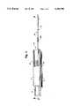
- FIG. 1is a perspective view of one embodiment of a tissue sampling instrument in accordance with the present invention
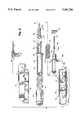
- FIG. 2is an exploded view of the instrument shown in FIG. 1;
- FIG. 3is sectional view along a plane indicated by a line 3--3 in FIG. 1, looking downwardly;
- FIGS. 4-7are sectional views similar to FIG. 3, illustrating sequential motions in arming the needle drive structures of the instrument;
- FIG. 8is a sectional view similar to FIGS. 3-7, illustrating release of the needle drive structures
- FIG. 9is sectional view along the plane indicated by line 9--9 in FIG. 4, illustrating a trigger mechanism for the needle drive structure
- FIG. 10is a distal view of the stylet and the cannula
- FIGS. 11 and 12are fragmentary views diagrammatically showing a representative tissue sampling operation of the needle portions of the instrument, partially in section;
- FIG. 13is a view similar to FIGS. 11 and 12, illustrating withdrawal of the needle portions extracting sample tissue;
- FIG. 14is a view similar to FIG. 13, illustrating discharge of the extracted tissue sample from the needle portion.
- FIGS. 15, 16 and 17are perspective, fragmentary views illustrating modification of the instrument in FIGS. 1 and 2 incorporating a variable stop structure to enable changing the length of needle displacement in tissue sampling operation of the instrument.
- Instrument 10has a longitudinally-split upper housing 12 and lower housing 14 from which a cocking or arming plunger button 16 projects rearwardly.
- An operating trigger button 18is molded on the upper housing 12 for manual depression through a housing slot 18a as best shown in FIG. 9 and more fully described hereinafter.
- the two-part needle structure of the instrument 10has a cylindrical cannula 20 through which an inner stylet 22 is slidably displaceable.
- the cannula 20projects from a movable cylinder structure 24 and as shown in FIG. 3, the rear opening 21 of the cylindrical cannula 20 opens through the cylinder head 25 into the cylinder bore 26.
- the styletis preferably (but need not be) a solid rod which projects from a piston structure 28 reciprocable through the cylinder bore 26.
- the forward end of the piston structure 28carries an externally mounted O-ring 29 to provide internal, pneumatic seal of the bore-chamber 26 to enable generation of reduced pressure therein which can be communicated through the annular clearance space 30 surrounding the stylet 22 within the cannula 20.
- the suction action of the communicated reduced pressureassists the extraction of the full-core tissue sample in operation as more fully described hereinafter with reference to FIGS. 11-14.
- the arming plunger button 16has an internal hub 17 which is fixed to the rear cylindrical portion 32 of a sear or arming coupler generally designated by reference character 34.
- a return coil spring 31surrounds the coupler cylinder 32 and bears at one end against the plunger button 16; the opposite spring end 33 is stationary and seats on an annular internal flange 35 of the housing 12, 14, through which the coupler cylinder 32 is axially displaceable.
- the expanded spring 31biases the plunger, arming button 16 in position extended from the housing 12, 14.
- the forward portion of the arming coupler 34has a pair of spaced, axially projecting coupler arms 36 with end barbs 37 which releasably latch and couple to the annular cylinder flange 40 radially extending from the moveable cylinder structure 24 during arming of the instrument 10 as later described with reference to FIG. 7.
- the piston structure 28is inserted within the coupler cylinder 32 and has an annular end flange 27 which seats on an internal wall 37 transversely extending across the cylinder 32 so that the piston structure 28 moves with the arming coupler 34.
- the piston flange 27also seats one end of drive spring 42 which bears at its other end 43 on the annular rear end of the cylinder 24.
- the drive spring 42thus urges the cylinder structure 24 forwardly so that in the unarmed condition of the expanded spring 42, the forward end of the cylinder head 25 is engaged against a cushion 44 seated on the internal end walls 12a, 14a of the housing 12, 14.
- the cylinder flange 40has a guide slot 40a which axially slides on a guide rib 40b formed on the bottom housing 14.
- the cylinder 24is slidably supported on a support flange 41 of the bottom housing 14.
- FIGS. 3-7illustrate the sequential positions in arming instrument 10 to prepare for tissue sampling operation.
- Arming of the instrumentbegins with manually depressing the plunger button 16 from the position shown in FIG. 3 through the positions in FIGS. 4 and 5 in which the return spring 31 is progressively compressed and the arming coupler 34 is forwardly advanced in the direction of arrow A in FIG. 4; the piston structure 28 is carried within the arming coupler 34 so that the stylet 22 is also advanced within the cannula 20 as indicated by arrow B in FIG. 4.
- the cylinder structure 24remains stationary since the cylinder head 25 abuts the cushion 44 and the advancing piston structure 28 reduces the volume of the cylinder bore chamber 26, as well as compressing the drive spring 42 against the stationary end of the cylinder 24.
- the cylinder bore chamber 26has been reduced to minimum volume as shown in FIG. 5 with completion of the advancing phase of the arming.
- the reverse phasecontinues the arming operation with manually yielding withdrawal of the plunger button 16 driven by expansion of the return spring 31 so that the reverse phase progresses from the position shown in FIG. 5 to the position shown in FIG. 7.
- the arming reverse phaseretracts the coupled cylinder structure 24 and piston structure 28 latched by the coupler arms 36 so that the drive spring 42 remains compressed as the cylinder 24, piston 28, and coupler 34 are retracted with the button 16 as indicated by arrow C in FIG. 6.
- the rearward retraction of the cylinder 24 and piston 28carries the stylet 22 and cannula 20 in the same rearward retraction into the housing 12, 14 without relative movement between the two needles so that the sharp stylet end 23 is slightly projecting from the sharp cannula end 13 and the cylinder bore chamber 26 remains at minimum volume.
- the reverse phase of the arming operationbrings an annular flange at the base of the coupling arms 36 into abutment against the housing flange 35 which thus serves as a stop for the reverse phase retraction of the coupler 34 and the coupled cylinder structure 24 which in turn defines the fully expanded position of the return spring 31 and arming plunger button 16.
- a window 11 formed in the housing 14 (or 12)is positioned to enable visibility of the retracted, armed position of the cylinder flange 40 and cylinder 24, which provides an optical monitor of the armed or unarmed condition of the instrument 10, and readiness for tissue sampling operation.
- a circumferential indicator band 20a on the cannula 20can be longitudinally located to visibly underlap or abut the housing nose 12b, 14b, through which the cannula is slidably supported, when the instrument is armed as shown in FIG. 7, but the indicator band is spaced from the housing nose 12b, 14b when the cannula 20 has been advanced as shown in FIG. 3 after completion of tissue sampling operation when the instrument is unarmed.
- FIG. 11the tissue sampling operation can begin as shown initially as in FIG. 11 in which the operator can direct the leading, stylet end 23 and cannula end 13 to the organ tissue T.
- the sharpened stylet end 23will assist pilot penetration [not shown] of the organ tissue T if the sample target lies at extended depth within the organ tissue T.
- FIGS. 11 and 12illustrate initial approach Of the stylet and cannula ends 23, 13 to the surface of the organ tissue T, for example, in obtaining mammary biopsy sample at shallow depth typically, approximately 2.5 centimeters from the stylet end 23.
- the tissue sampling operationcan be triggered as illustrated with reference to FIGS. 8 and 9 by depressing the trigger button 18.
- the trigger button 18has a pair of spaced, downwardly projecting trigger arms 19 which are respectively wedged between the exterior cylindrical surface of the cylinder structure 24 and the radially inner surface of the respective coupler arms 36. Depression of the trigger button 18 lowers the trigger arms 19 and cam portions 19a further wedge the coupler arms 36 radially outwardly, shown in FIG.
- the induced suction action Epromotes aspiration of a target tissue sample S core rearwardly as indicated by directional arrow F through the bore of the cannula 20 at the same time that the core sample S is severed from the surrounding tissue T by the forward advance of the sharp cannula end 13 as indicated by arrows D.
- the cushion stop 44absorbs the impact of the cylinder head 25 and in this position the cylinder bore chamber 26 has expanded to its maximum volume; as the cannula 20 reaches maximum displacement relative to the stylet 22 as shown in FIG. 10 corresponding to FIG. 3, the maximum length of the severed and aspirated core sample S is drawn into the cannula 20 ahead of the relatively stationary stylet 22.
- the operatorretracts the entire instrument 10 to withdraw the cannula 20 from the organ tissue T and the reduced pressure within the annular clearance 30 promotes the retention of the severed core sample S with the retracted cannula 20.
- the core tissue sample Scan be discharged from the cannula 20 by the relative advance of the stylet 22 as shown in FIG. 14 as the instrument is rearmed in the advance phase between the positions shown in FIGS. 3-5.
- the cushion 44can be replaced by a manually variable stop member generally designated by reference character 46.
- the variable stop member 46is a molded elastomeric in which two rearwardly projecting axial lobes 48 have a generally quarter-round configuration and are arranged in radially opposing alignment separated with central clearance for the cannula and stylet.
- Recess flutes 50are radially arranged in alternation with the lobes 48.
- the flutes 50can accept the axially projecting lobes 27 of the cylinder head 25 allowing a full advance stroke, for example of 2.5 centimeters displacement of the cannula 20 in the tissue sampling operating displacement thereof.
- variable stop 46can be manually rotated by the integral grip portion 51 which is accessible on the forward exterior of the housing 12, 14 as shown in FIG. 15, so that the stop lobes 48 are rotated by 90 degrees into the approaching path for abutting alignment with the cylinder head lobes 27.
- the abutmentresults in an abbreviated tissue sampling stroke, for example of approximately 1.3 centimeters displacement of the cannula 20, as governed by the depth of the target tissue sample and the desired length of the sample core to be extracted.
- the grip portion 51 of the variable stop member 46has a generally square configuration provided with differential indicia 52 formed on one or both of adjacent quarter sides of the grip 51 to indicate the selective, quarter-turn orientations of the stop lobes 48 and resulting stroke length of the tissue sampling instrument operation. Additionally, indexing grooves 53 can be molded into the inner surface of the grip portion 51 for receiving a raised rib (not shown) on the outer surface of the housing 12, 14 in order to releasably retain the selective rotational position of the stop lobes 48.
Landscapes
- Health & Medical Sciences (AREA)
- Life Sciences & Earth Sciences (AREA)
- Medical Informatics (AREA)
- Engineering & Computer Science (AREA)
- Biomedical Technology (AREA)
- Heart & Thoracic Surgery (AREA)
- Pathology (AREA)
- Molecular Biology (AREA)
- Surgery (AREA)
- Animal Behavior & Ethology (AREA)
- General Health & Medical Sciences (AREA)
- Public Health (AREA)
- Veterinary Medicine (AREA)
- Sampling And Sample Adjustment (AREA)
Abstract
Description
Claims (24)
Priority Applications (1)
| Application Number | Priority Date | Filing Date | Title |
|---|---|---|---|
| US08/056,256US5392790A (en) | 1993-04-30 | 1993-04-30 | Instrument for obtaining bore type tissue sampling |
Applications Claiming Priority (1)
| Application Number | Priority Date | Filing Date | Title |
|---|---|---|---|
| US08/056,256US5392790A (en) | 1993-04-30 | 1993-04-30 | Instrument for obtaining bore type tissue sampling |
Publications (1)
| Publication Number | Publication Date |
|---|---|
| US5392790Atrue US5392790A (en) | 1995-02-28 |
Family
ID=22003219
Family Applications (1)
| Application Number | Title | Priority Date | Filing Date |
|---|---|---|---|
| US08/056,256Expired - Fee RelatedUS5392790A (en) | 1993-04-30 | 1993-04-30 | Instrument for obtaining bore type tissue sampling |
Country Status (1)
| Country | Link |
|---|---|
| US (1) | US5392790A (en) |
Cited By (34)
| Publication number | Priority date | Publication date | Assignee | Title |
|---|---|---|---|---|
| US5476099A (en)* | 1994-08-31 | 1995-12-19 | Boston Scientific Corporation | High velocity tissue sample cutter |
| US5601588A (en)* | 1994-09-29 | 1997-02-11 | Olympus Optical Co., Ltd. | Endoscopic puncture needle |
| EP0780089A1 (en)* | 1995-12-18 | 1997-06-25 | Libero Luppi | Device for taking biobsy samples, particularly of soft tissues |
| US5779647A (en) | 1995-06-07 | 1998-07-14 | Chau; Sonny | Automated biopsy instruments |
| US5876354A (en)* | 1996-05-01 | 1999-03-02 | Emx | Biopsy needle hub assembly |
| US6142955A (en) | 1997-09-19 | 2000-11-07 | United States Surgical Corporation | Biopsy apparatus and method |
| US6402701B1 (en) | 1999-03-23 | 2002-06-11 | Fna Concepts, Llc | Biopsy needle instrument |
| WO2001089389A3 (en)* | 2000-05-25 | 2002-10-10 | Beniamino Palmieri | Biopsy device |
| US20030216667A1 (en)* | 2000-09-11 | 2003-11-20 | Frank Viola | Biopsy system |
| US20030225343A1 (en)* | 2002-05-31 | 2003-12-04 | Promex, Llc | Biopsy needle with integrated guide pin |
| US6716619B1 (en)* | 2001-02-08 | 2004-04-06 | Clinomics Biosciences, Inc. | Stylet for use with tissue microarrayer and molds |
| US20040167432A1 (en)* | 1998-03-03 | 2004-08-26 | Senorx, Inc. | Breast biopsy system and methods |
| US20040225229A1 (en)* | 2000-11-27 | 2004-11-11 | Viola Frank J. | Tissue sampling and removal apparatus and method |
| US20080183175A1 (en)* | 2007-01-26 | 2008-07-31 | Laurimed Llc | Styli used to position device for carrying out selective discectomy |
| US20080188826A1 (en)* | 2007-02-01 | 2008-08-07 | Laurimed, Llc | Methods and devices for treating tissue |
| US20090259126A1 (en)* | 2008-04-02 | 2009-10-15 | Laurimed, Llc | Methods and devices for delivering injections |
| US20090299220A1 (en)* | 2008-05-30 | 2009-12-03 | Inrad, Inc. | Biopsy Device Having Specimen Length Adjustment |
| US20090299221A1 (en)* | 2008-05-30 | 2009-12-03 | Inrad, Inc. | Apparatus for Cocking a Biopsy Device |
| US8292909B1 (en) | 2010-06-30 | 2012-10-23 | Laurimed, Llc | Devices and methods for cutting tissue |
| US8657842B2 (en) | 2010-06-30 | 2014-02-25 | Laurimed, Llc | Devices and methods for cutting tissue |
| US20140213932A1 (en)* | 2010-02-25 | 2014-07-31 | Promex Technologies, Llc | Full Core Biopsy Device |
| US8815099B1 (en) | 2014-01-21 | 2014-08-26 | Laurimed, Llc | Devices and methods for filtering and/or collecting tissue |
| WO2015081309A1 (en)* | 2013-11-26 | 2015-06-04 | Hologic, Inc. | Biopsy device arming mechanism |
| EP3009075A1 (en) | 2014-10-13 | 2016-04-20 | NeoDynamics AB | Distal tip tissue sampling arrangement |
| EP3009076A1 (en) | 2014-10-13 | 2016-04-20 | NeoDynamics AB | Trocar arrangement for tissue sampling device |
| WO2016196536A1 (en)* | 2015-06-02 | 2016-12-08 | Robert Peliks | Tissue removal device and method of use |
| US9763731B2 (en) | 2012-02-10 | 2017-09-19 | Myromed, Llc | Vacuum powered rotary devices and methods |
| US9968338B2 (en) | 2012-11-21 | 2018-05-15 | C. R. Bard, Inc. | Core needle biopsy device |
| WO2018174882A1 (en)* | 2017-03-23 | 2018-09-27 | Spiration, Inc., d.b.a. Olympus Respiratory America | Needle handle with vacuum chamber |
| EP3616625A1 (en) | 2018-09-03 | 2020-03-04 | NeoDynamics AB | A biopsy arrangement |
| EP3791794A1 (en) | 2019-09-12 | 2021-03-17 | NeoDynamics AB (publ) | A biopsy arrangement |
| WO2023064471A1 (en)* | 2021-10-15 | 2023-04-20 | Atrion Medical Products, Inc. | Advanced actuating mechanism and method of operation for fluid displacement and pressurizing device |
| US12208194B2 (en) | 2018-06-13 | 2025-01-28 | Stryker European Operations Limited | Bone fragment collector and processor |
| US12274629B2 (en) | 2019-12-18 | 2025-04-15 | Stryker European Operations Limited | Bone fragment collector and processor |
Citations (10)
| Publication number | Priority date | Publication date | Assignee | Title |
|---|---|---|---|---|
| US2708437A (en)* | 1952-03-31 | 1955-05-17 | Elizabeth Painter Hutchins | Surgical instrument |
| US3844272A (en)* | 1969-02-14 | 1974-10-29 | A Banko | Surgical instruments |
| SU728852A1 (en)* | 1978-05-11 | 1980-04-25 | Хабаровский государственный медицинский институт | Needle for punction biopsy |
| US4396021A (en)* | 1980-12-15 | 1983-08-02 | Baumgartner George C | Surgical instrument and process |
| US4598710A (en)* | 1984-01-20 | 1986-07-08 | Urban Engineering Company, Inc. | Surgical instrument and method of making same |
| US4766907A (en)* | 1986-10-15 | 1988-08-30 | Groot William J De | Apparatus and method for performing a biopsy and a device for manipulating same |
| US4953558A (en)* | 1987-11-19 | 1990-09-04 | C. R. Bard, Inc. | Tissue sampling device |
| US5156160A (en)* | 1990-06-22 | 1992-10-20 | Bennett Lavon L | Adjustable biopsy device capable of controlling tissue sample size collected thereby |
| US5172701A (en)* | 1990-02-28 | 1992-12-22 | Medical Device Technologies, Inc. | Single use automated soft tissue aspiration biopsy device |
| US5224470A (en)* | 1990-02-28 | 1993-07-06 | Angiomed Ag | Apparatus for biopsy sampling with needle and stylet moveable in opposite directions |
- 1993
- 1993-04-30USUS08/056,256patent/US5392790A/ennot_activeExpired - Fee Related
Patent Citations (10)
| Publication number | Priority date | Publication date | Assignee | Title |
|---|---|---|---|---|
| US2708437A (en)* | 1952-03-31 | 1955-05-17 | Elizabeth Painter Hutchins | Surgical instrument |
| US3844272A (en)* | 1969-02-14 | 1974-10-29 | A Banko | Surgical instruments |
| SU728852A1 (en)* | 1978-05-11 | 1980-04-25 | Хабаровский государственный медицинский институт | Needle for punction biopsy |
| US4396021A (en)* | 1980-12-15 | 1983-08-02 | Baumgartner George C | Surgical instrument and process |
| US4598710A (en)* | 1984-01-20 | 1986-07-08 | Urban Engineering Company, Inc. | Surgical instrument and method of making same |
| US4766907A (en)* | 1986-10-15 | 1988-08-30 | Groot William J De | Apparatus and method for performing a biopsy and a device for manipulating same |
| US4953558A (en)* | 1987-11-19 | 1990-09-04 | C. R. Bard, Inc. | Tissue sampling device |
| US5172701A (en)* | 1990-02-28 | 1992-12-22 | Medical Device Technologies, Inc. | Single use automated soft tissue aspiration biopsy device |
| US5224470A (en)* | 1990-02-28 | 1993-07-06 | Angiomed Ag | Apparatus for biopsy sampling with needle and stylet moveable in opposite directions |
| US5156160A (en)* | 1990-06-22 | 1992-10-20 | Bennett Lavon L | Adjustable biopsy device capable of controlling tissue sample size collected thereby |
Cited By (76)
| Publication number | Priority date | Publication date | Assignee | Title |
|---|---|---|---|---|
| US5476099A (en)* | 1994-08-31 | 1995-12-19 | Boston Scientific Corporation | High velocity tissue sample cutter |
| US5601588A (en)* | 1994-09-29 | 1997-02-11 | Olympus Optical Co., Ltd. | Endoscopic puncture needle |
| US6626850B1 (en) | 1995-06-07 | 2003-09-30 | Allegiance Corporation | Automated biopsy instruments |
| US5779647A (en) | 1995-06-07 | 1998-07-14 | Chau; Sonny | Automated biopsy instruments |
| EP0780089A1 (en)* | 1995-12-18 | 1997-06-25 | Libero Luppi | Device for taking biobsy samples, particularly of soft tissues |
| US5876354A (en)* | 1996-05-01 | 1999-03-02 | Emx | Biopsy needle hub assembly |
| US6142955A (en) | 1997-09-19 | 2000-11-07 | United States Surgical Corporation | Biopsy apparatus and method |
| US20040167432A1 (en)* | 1998-03-03 | 2004-08-26 | Senorx, Inc. | Breast biopsy system and methods |
| US6402701B1 (en) | 1999-03-23 | 2002-06-11 | Fna Concepts, Llc | Biopsy needle instrument |
| US6689072B2 (en) | 1999-03-23 | 2004-02-10 | Leopold S. Kaplan | Biopsy needle instrument |
| WO2001089389A3 (en)* | 2000-05-25 | 2002-10-10 | Beniamino Palmieri | Biopsy device |
| US20030216667A1 (en)* | 2000-09-11 | 2003-11-20 | Frank Viola | Biopsy system |
| US7189207B2 (en) | 2000-09-11 | 2007-03-13 | Tyco Healthcare Group Lp | Biopsy system having a single use loading unit operable with a trocar driver, a knife driver and firing module |
| US6712773B1 (en) | 2000-09-11 | 2004-03-30 | Tyco Healthcare Group Lp | Biopsy system |
| US8128577B2 (en) | 2000-09-11 | 2012-03-06 | Tyco Healthcare Group Lp | Biopsy system |
| US20070118049A1 (en)* | 2000-09-11 | 2007-05-24 | Tyco Healthcare Group Lp | Biopsy system |
| US6860860B2 (en) | 2000-11-27 | 2005-03-01 | Tyco Healthcare Group, Lp | Tissue sampling and removal apparatus and method |
| US20040225229A1 (en)* | 2000-11-27 | 2004-11-11 | Viola Frank J. | Tissue sampling and removal apparatus and method |
| US7513877B2 (en) | 2000-11-27 | 2009-04-07 | Tyco Healthcare Group Lp | Tissue sampling and removal apparatus and method |
| US6716619B1 (en)* | 2001-02-08 | 2004-04-06 | Clinomics Biosciences, Inc. | Stylet for use with tissue microarrayer and molds |
| US6918881B2 (en) | 2002-05-31 | 2005-07-19 | Promex Technologies, Llc | Biopsy needle with integrated guide pin |
| US20030225343A1 (en)* | 2002-05-31 | 2003-12-04 | Promex, Llc | Biopsy needle with integrated guide pin |
| US8414587B2 (en) | 2007-01-26 | 2013-04-09 | Laurimed, Llc | Styli used to position device for carrying out selective discetomy |
| US20080183175A1 (en)* | 2007-01-26 | 2008-07-31 | Laurimed Llc | Styli used to position device for carrying out selective discectomy |
| US20080183192A1 (en)* | 2007-01-26 | 2008-07-31 | Laurimed Llc | Contralateral insertion method to treat herniation with device using visualization components |
| US20080188826A1 (en)* | 2007-02-01 | 2008-08-07 | Laurimed, Llc | Methods and devices for treating tissue |
| US8277437B2 (en) | 2008-04-02 | 2012-10-02 | Laurimed, Llc | Method of accessing two lateral recesses |
| US20090259126A1 (en)* | 2008-04-02 | 2009-10-15 | Laurimed, Llc | Methods and devices for delivering injections |
| US20090299220A1 (en)* | 2008-05-30 | 2009-12-03 | Inrad, Inc. | Biopsy Device Having Specimen Length Adjustment |
| US8197419B2 (en) | 2008-05-30 | 2012-06-12 | Inrad, Inc. | Biopsy device having specimen length adjustment |
| US8192369B2 (en) | 2008-05-30 | 2012-06-05 | Inrad, Inc. | Apparatus for cocking a biopsy device |
| US20090299221A1 (en)* | 2008-05-30 | 2009-12-03 | Inrad, Inc. | Apparatus for Cocking a Biopsy Device |
| US8506504B2 (en) | 2008-05-30 | 2013-08-13 | Inrad, Inc. | Biopsy device having specimen length adjustment assembly including throw stop adjustable by rotation of distal nose on housing |
| US9463002B2 (en)* | 2010-02-25 | 2016-10-11 | JJ Dogs LLC | Full core biopsy device |
| US20140213932A1 (en)* | 2010-02-25 | 2014-07-31 | Promex Technologies, Llc | Full Core Biopsy Device |
| US8840632B2 (en) | 2010-06-30 | 2014-09-23 | Laurimed, Llc | Devices and methods for cutting tissue |
| US8292909B1 (en) | 2010-06-30 | 2012-10-23 | Laurimed, Llc | Devices and methods for cutting tissue |
| US8657842B2 (en) | 2010-06-30 | 2014-02-25 | Laurimed, Llc | Devices and methods for cutting tissue |
| US8298254B2 (en) | 2010-06-30 | 2012-10-30 | Laurimed, Llc | Devices and methods for cutting and evacuating tissue |
| US8882793B2 (en) | 2010-06-30 | 2014-11-11 | Laurimed, Llc | Devices and methods for cutting tissue |
| US9532796B2 (en) | 2010-06-30 | 2017-01-03 | Myromed, Llc | Devices and methods for cutting tissue |
| US8685052B2 (en) | 2010-06-30 | 2014-04-01 | Laurimed, Llc | Devices and methods for cutting tissue |
| US9770289B2 (en) | 2012-02-10 | 2017-09-26 | Myromed, Llc | Vacuum powered rotary devices and methods |
| US9763731B2 (en) | 2012-02-10 | 2017-09-19 | Myromed, Llc | Vacuum powered rotary devices and methods |
| US11793497B2 (en) | 2012-11-21 | 2023-10-24 | C.R. Bard, Inc. | Core needle biopsy device |
| US11013499B2 (en) | 2012-11-21 | 2021-05-25 | C. R. Bard, Inc. | Core needle biopsy device |
| US9968338B2 (en) | 2012-11-21 | 2018-05-15 | C. R. Bard, Inc. | Core needle biopsy device |
| US10537311B2 (en) | 2013-11-26 | 2020-01-21 | Hologic, Inc. | Biopsy device arming mechanism |
| US20200155128A1 (en)* | 2013-11-26 | 2020-05-21 | Hologic, Inc. | Biopsy device arming mechanism |
| US9585639B2 (en) | 2013-11-26 | 2017-03-07 | Hologic, Inc. | Biopsy device arming mechanism |
| WO2015081309A1 (en)* | 2013-11-26 | 2015-06-04 | Hologic, Inc. | Biopsy device arming mechanism |
| US12342997B2 (en) | 2013-11-26 | 2025-07-01 | Hologic, Inc. | Biopsy device arming mechanism |
| AU2014354670B2 (en)* | 2013-11-26 | 2018-11-01 | Hologic, Inc. | Biopsy device arming mechanism |
| US11832802B2 (en)* | 2013-11-26 | 2023-12-05 | Hologic, Inc. | Biopsy device arming mechanism |
| US8815099B1 (en) | 2014-01-21 | 2014-08-26 | Laurimed, Llc | Devices and methods for filtering and/or collecting tissue |
| EP3009075A1 (en) | 2014-10-13 | 2016-04-20 | NeoDynamics AB | Distal tip tissue sampling arrangement |
| US10342519B2 (en) | 2014-10-13 | 2019-07-09 | Neodynamics Ab | Trocar arrangement for tissue sampling device |
| WO2016058844A1 (en) | 2014-10-13 | 2016-04-21 | Neodynamics Ab | Distal tip tissue sampling arrangement |
| EP3009076A1 (en) | 2014-10-13 | 2016-04-20 | NeoDynamics AB | Trocar arrangement for tissue sampling device |
| US11083441B2 (en) | 2014-10-13 | 2021-08-10 | Neodynamics Ab | Distal tip tissue sampling arrangement |
| WO2016196536A1 (en)* | 2015-06-02 | 2016-12-08 | Robert Peliks | Tissue removal device and method of use |
| US11311278B2 (en) | 2015-06-02 | 2022-04-26 | Merit Medical Systems, Inc. | Tissue removal device and method of use |
| US11992196B2 (en) | 2017-03-23 | 2024-05-28 | Gyrus Acmi, Inc. | Needle handle with vacuum chamber |
| WO2018174882A1 (en)* | 2017-03-23 | 2018-09-27 | Spiration, Inc., d.b.a. Olympus Respiratory America | Needle handle with vacuum chamber |
| US11406365B2 (en)* | 2017-03-23 | 2022-08-09 | Gyrus Acmi, Inc. | Needle handle with vacuum chamber |
| US12208194B2 (en) | 2018-06-13 | 2025-01-28 | Stryker European Operations Limited | Bone fragment collector and processor |
| EP3616625A1 (en) | 2018-09-03 | 2020-03-04 | NeoDynamics AB | A biopsy arrangement |
| WO2020048888A1 (en) | 2018-09-03 | 2020-03-12 | Neodynamics Ab (Publ) | A biopsy arrangement |
| US12369894B2 (en) | 2018-09-03 | 2025-07-29 | Neonavia Ab | Biopsy arrangement |
| WO2021047984A1 (en) | 2019-09-12 | 2021-03-18 | Neodynamics Ab (Publ) | A biopsy arrangement |
| EP3791794A1 (en) | 2019-09-12 | 2021-03-17 | NeoDynamics AB (publ) | A biopsy arrangement |
| US12274629B2 (en) | 2019-12-18 | 2025-04-15 | Stryker European Operations Limited | Bone fragment collector and processor |
| US12121683B2 (en) | 2021-10-15 | 2024-10-22 | Atrion Medical Products, Inc. | Advanced actuating mechanism and method of operation for fluid displacement and pressurizing device |
| US12138408B2 (en) | 2021-10-15 | 2024-11-12 | Atrion Medical Products, Inc. | Advanced actuating mechanism and method of operation for fluid displacement and pressurizing device |
| WO2023064471A1 (en)* | 2021-10-15 | 2023-04-20 | Atrion Medical Products, Inc. | Advanced actuating mechanism and method of operation for fluid displacement and pressurizing device |
| EP4415791A4 (en)* | 2021-10-15 | 2025-08-20 | Atrion Medical Products Inc | ADVANCED ACTUATION MECHANISM AND OPERATING METHOD FOR FLUID DISPLACEMENT AND PRESSURIZATION DEVICE |
Similar Documents
| Publication | Publication Date | Title |
|---|---|---|
| US5392790A (en) | Instrument for obtaining bore type tissue sampling | |
| US11793497B2 (en) | Core needle biopsy device | |
| US5713368A (en) | Single use automated soft tissue aspiration biopsy device | |
| US5121751A (en) | Instrument for tissue sampling | |
| US5243994A (en) | Instrument for tissue sampling including a carriage assembly | |
| US11179142B2 (en) | Biopsy device | |
| EP1673015B1 (en) | Vacuum assisted biopsy needle set | |
| US5617874A (en) | Automated biopsy instrument | |
| EP0186256B1 (en) | Biopsy needle set | |
| US5752923A (en) | Biopsy instrument with handle and needle set | |
| US5188118A (en) | Automatic biopsy instrument with independently actuated stylet and cannula | |
| CN1149957C (en) | Instrument and apparatus for biopsy and method thereof | |
| CN116158791B (en) | Biopsy needle for easy retraction | |
| CN120420012A (en) | biopsy needle | |
| JP3074445B2 (en) | Biopsy device | |
| JPH04282145A (en) | Biopsy needle device | |
| US7530987B1 (en) | Surgical tool for creating an incision in a tubular vessel | |
| CN219207056U (en) | Double-tube negative pressure biopsy needle | |
| CN112089426A (en) | Negative pressure blood sampling pen | |
| EP1289425A2 (en) | Biopsy device | |
| CN120203643A (en) | Biopsy needle | |
| CN117530729A (en) | Full-automatic biopsy gun capable of shifting |
Legal Events
| Date | Code | Title | Description |
|---|---|---|---|
| AS | Assignment | Owner name:RYDER INTERNATIONAL CORPORATION, ALABAMA Free format text:ASSIGNMENT OF ASSIGNORS INTEREST;ASSIGNORS:KANNER, ROWLAND W.;DAVIS, RICHARD M.;REEL/FRAME:006807/0154 Effective date:19930518 | |
| AS | Assignment | Owner name:RYDER INTERNATIONAL CORPORATION, ALABAMA Free format text:CERTIFIED DOCUMENT - CERTIFICATION BY SECRETARY OF STATE OF ALABAMA ON BACK OF LAST PAGE;ASSIGNORS:RYDER INTERNATIONAL CORPORATION (A CORP. OF DELAWARE) (MERGED INTO);NEW RYDER CORPORATION (A CORP. OF ALABAMA) (CHANGED TO);REEL/FRAME:007147/0233 Effective date:19921210 | |
| AS | Assignment | Owner name:RIC ACQUISITION CORPORATION, ALABAMA Free format text:ASSIGNMENT OF ASSIGNORS INTEREST;ASSIGNOR:RYDER INTERNATIONAL CORPORATION;REEL/FRAME:007167/0597 Effective date:19940419 | |
| AS | Assignment | Owner name:RYDER INTERNATIONAL CORPORATION, ALABAMA Free format text:CHANGE OF NAME;ASSIGNOR:RIC ACQUISITION CORPORATION;REEL/FRAME:007194/0411 Effective date:19940419 | |
| AS | Assignment | Owner name:ATRION MEDICAL PRODUCTS, INC., ALABAMA Free format text:MERGER;ASSIGNOR:RYDER INTERNATIONAL CORPORATION;REEL/FRAME:008519/0569 Effective date:19961211 | |
| FEPP | Fee payment procedure | Free format text:PAT HOLDER CLAIMS SMALL ENTITY STATUS - SMALL BUSINESS (ORIGINAL EVENT CODE: SM02); ENTITY STATUS OF PATENT OWNER: SMALL ENTITY | |
| FPAY | Fee payment | Year of fee payment:4 | |
| FEPP | Fee payment procedure | Free format text:PAYOR NUMBER ASSIGNED (ORIGINAL EVENT CODE: ASPN); ENTITY STATUS OF PATENT OWNER: SMALL ENTITY | |
| FPAY | Fee payment | Year of fee payment:8 | |
| REMI | Maintenance fee reminder mailed | ||
| LAPS | Lapse for failure to pay maintenance fees | ||
| STCH | Information on status: patent discontinuation | Free format text:PATENT EXPIRED DUE TO NONPAYMENT OF MAINTENANCE FEES UNDER 37 CFR 1.362 | |
| FP | Lapsed due to failure to pay maintenance fee | Effective date:20070228 |