US5392765A - Continuous flow cystoscope - Google Patents
Continuous flow cystoscopeDownload PDFInfo
- Publication number
- US5392765A US5392765AUS08/017,475US1747593AUS5392765AUS 5392765 AUS5392765 AUS 5392765AUS 1747593 AUS1747593 AUS 1747593AUS 5392765 AUS5392765 AUS 5392765A
- Authority
- US
- United States
- Prior art keywords
- inner member
- outer sheath
- channel
- inlet
- defining
- Prior art date
- Legal status (The legal status is an assumption and is not a legal conclusion. Google has not performed a legal analysis and makes no representation as to the accuracy of the status listed.)
- Expired - Lifetime
Links
Images

Classifications
- A—HUMAN NECESSITIES
- A61—MEDICAL OR VETERINARY SCIENCE; HYGIENE
- A61B—DIAGNOSIS; SURGERY; IDENTIFICATION
- A61B1/00—Instruments for performing medical examinations of the interior of cavities or tubes of the body by visual or photographical inspection, e.g. endoscopes; Illuminating arrangements therefor
- A61B1/307—Instruments for performing medical examinations of the interior of cavities or tubes of the body by visual or photographical inspection, e.g. endoscopes; Illuminating arrangements therefor for the urinary organs, e.g. urethroscopes, cystoscopes
Definitions
- This inventionrelates to a continuous flow instrument, such as a continuous flow endoscope, which may be used as a hysteroscope or cystoscope and more particularly relates to a continuous flow cystoscope having an outer sheath which has a hollowed-out central area which terminates in a distal end having an elongated fenestra and a means for defining an inner member which is located within the hollowed-out central area wherein the means defining the inner member includes means for defining an inner member channel having a first passageway receiving a telescope and a second passageway for passing a working tool. The inner member channel terminates in a distal end having an irrigation inlet.
- the inner memberfurther includes means defining an elongated lip.
- the inner memberis spaced from the inner surface of the outer sheath to define a fluid passageway for irrigant outflow and the elongated fenestra of the outer sheath and the elongated lip of the inner member cooperate to define a fenestra channel having an irrigation outlet.
- the fenestra channelcommunicates with the liquid passageway.
- the flow path traversed by the fluidis along a path having reduced fluid turbulence at the irrigation inlet and operative site.
- the second passagewaymay be used to pass a working tool such as a laser fiber for the incision, excision, ablation and hemostasis of the lower genitourinary tract including prostatic tissue.
- Continuous flow resectoscopesare well known in the art.
- U.S. Pat. No. 3,835,842discloses a continuous flow resectoscope for use in urology. Continuous flow resectoscopes have been used for other surgical procedures.
- the Auhll Referencediscloses that the use of a continuous flow electrical resectoscope system (CFR) includes a continuous flow irrigation system.
- CFRcontinuous flow electrical resectoscope system
- the continuous flow irrigation systemprovides sufficient flow and pressure to distend and expand the uterus to enable the surgeon to perform the desired procedure.
- a Uterine Resectoscope Systemis used for three operative procedures: (i) Myoma resection; (ii) endometrial ablation; and (iii) cynical septa dissection.
- the presently known continuous flow resectoscope and continuous flow hysteroscope systemsgenerally pass an irrigating fluid through the center of an inner sheath and out of the distal end to irrigate the operative site. Fluid is removed from the operative site by passing the fluid through a passageway formed between the outer surface of an inner sheath and the inner surface of an outer sheath.
- fluid flowis obtained by positioning the source of fluid at a predetermined height in the operating room. For example, positioning a bag of saline fluid at approximately 1 meter above the operating table will produce 75 mm of mercury head pressure. At a height of 1.4 meter produces approximately 103 mm of mercury pressure at the outlet of the source. The pressure drop through the various tubing and through the resectoscope drops the pressure to a range of 60 mm of mercury to 90 mm of mercury at the distal end of the hysteroscope.
- Continuous flow hysteroscopesare known in the art and comprise an outer sheath having an outer surface, an inner surface and a hollowed out central area extending along a central axis.
- the outer sheathhas an outer surface, an inner surface and a hollowed out central area extending along a central axis.
- the outer sheathhas a distal section which terminates in a distal end and means are located at the distal section for defining around the outer surface of the sheath a plurality of openings which extend between the outer surface of the sheath and the inner surface. The plurality of openings pass fluid exterior to the distal section therethrough and into the hollowed out central area.
- the continuous flow hysteroscopefurther includes means defining an inner member positioned within the outer sheath for defining a fluid passageway which is adapted to pass irrigation fluid passed from the operation site through the plurality of openings into the fluid passageway and out of an outlet port located at the proximal end of the outer sheath.
- the inner memberincludes means defining a first channel and second channel which are adapted to receive a telescope and a working tool, respectively. An additional accessory or working channel may also be provided.
- the first and/or second channelpass irrigation fluid from an inlet port, through the inner member and out of the distal end of the inner member to the operative site.
- the irrigation fluidis passed over the distal end of the telescope and traverses a flow path to the plurality of openings which are located in substantially the same section as the distal end of the telescope.
- the present inventiondiscloses a novel, unique and improved continuous flow instrument which is adapted for use as a continuous flow cystoscope.
- the cystoscopecomprises an outer sheath having an outer surface, an inner surface and a hollowed-out central area extending along a central axis which extends therethrough.
- the sheathhas a proximal section and a distal section.
- the distal sectionincludes means defining an opening and an elongated fenestra extending distally from the distal section of the outer sheath.
- the elongated fenestraextends along a path substantially parallel to and spaced from the central axis.
- the cystoscopefurther includes means defining an inner member adopted to be positioned within said hollowed-out area wherein the inner member defining means includes means for defining an outer wall located around the periphery of the inner member which is adapted to be spaced from the inner surface of the outer sheath for defining a fluid passageway.
- the means defining the inner memberincludes means defining an inner member channel having a first passageway which is adapted to receive a telescope and a second passageway which is adapted for passing a working tool.
- the distal end of the inner memberhas an elongated lip which cooperates with the elongated fenestra to form a fenestra channel having an irrigation outlet.
- the inner member channelis operatively connected to an inlet port located at the proximal section of the outer sheath for passing fluid through the inner member channel, through an irrigation inlet located at the distal end of the inner member.
- the fluid flow pathis through the inner member channel, past the distal end of a telescope and the working tool extending distally from the channel over a flow path having reduced turbulence to the irrigation outlet, through the fenestra channel, through the fluid passageway and through the outlet port of the outer sheath.
- the method for performing a surgical procedurecomprises the step of assembling a continuous flow instrument comprising an outer sheath having an outer surface, and inner surface and a hollowed-out central area wherein the outer sheath has a proximal section having an outlet port and an inlet port and a distal section having an opening and an elongated fenestra extending therefrom and means defining an inner member positioned within the hollowed-out central area and wherein the inner member includes means for defining an exterior surface located around the periphery of the inner member which is adapted to be spaced from the inner surface of the outer sheath for defining a fluid passageway, means defining a distal end and an irrigation inlet wherein the distal end and irrigation inlet are positioned in the opening of the outer sheath and an elongated lip wherein the elongated lip cooperates with the elongated fenestra to define a
- the prior art continuous flow hysteroscope systemsutilize an outer sheath, an inner sheath, a visual obturator for introduction and diagnostic purposes, an operating bridge for operating procedures and additional components in order to perform diagnostic and/or operative procedures.
- the prior art continuous flow resectoscope/hysteroscope systems having an inner sheath and outer sheath structuredo provide a clear visualization of the uterine cavity during diagnostic and operative procedures.
- the overall diameter of the outer sheathremained in the 10 mm to 12 mm range.
- the prior art continuous flow hysteroscopeeliminated the inner sheath and replaced the inner sheath with an inner member. As such, the same fluid throughput flow and the size of the accessory or working channel were maintained while reducing the overall outer sheath size or diameter.
- the outside diameter of the outer sheathis in the range of about 7 mm to about 8 mm. A smaller sheath size is important to enable the gynecologist to minimize dilation of the cervix prior to insertion of the hysteroscope into the uterine cavity.
- one of the operating problems associated with the continuous flow hysteroscopeis that the path of fluid flow produces fluid turbulence in the vicinity of the distal end of the telescope which may, from time-to-time, partially or completely momentarily block the field of view or result in short durations of an obstructed outflow channel over the fluid flow path from the irrigation outlet at the distal end of the inner member to the plurality of holes in the distal section of the outer sheath.
- the holes in the distal section of the outer sheathcan be covered by tissue thereby preventing an outflow of irrigant.
- This obstruction of outflowis a particular problem in the urological continuous flow resectoscope because the outflow holes in the outer sheath are often covered by the urethral lining.
- the continuous flow cystoscope of the present inventionovercomes certain of the disadvantages of the prior art continuous flow instruments.
- the advantageous structural relationship between the outer sheath and inner memberis maintained to take advantage of the reduced overall outer sheath size having a diameter, in the preferred embodiment, of about 8 mm.
- the reduced diameter of the overall sheath sizeis desirable to reduce trauma to a patient during insertion of the cystoscope into the urethra of a patient.
- the outer sheathhas an elongated fenestra formed on the distal section which cooperates with an elongated lip formed on the distal end of the inner member to define a fenestra channel.
- the fenestra channelhas an irrigation outlet which is located distally from the irrigation inlet in the inner member and from a working tool which is passed through the inner member channel and positioned to extend beyond the distal end of the telescope viewing means positioned within the inner member.
- the distal tip of a telescopeis located in the vicinity of the distal end of the inner member. As such, the irrigation fluid passes through the inner member channel and flows in a flow pattern past the distal end of the telescope and the distal end of the working tool.
- the structure and placement of the fenestra channel and the irrigation outlet for the fenestra channelresult in the establishment of a flow of the irrigation fluid emanating from the distal end of the inner member over a flow path having reduced fluid turbulence in that the irrigation fluid converges at the irrigation outlet of the fenestra channel at a location distally remote from the irrigation inlet, the working tool and the distal end of the telescope.
- the fluid flowhas less turbulence and results in immediate removal of image impeding material such as blood or tissue in the fluid flow which would otherwise obstruct the field of view.
- the fluid flow pathis in a direction which transports any image impeding material into the irrigation outlet, through the fenestra channel, through the fluid passageway and out of the outlet port located at the proximal end of the outer sheath.
- the continuous flow cystoscopeincludes a shaped fenestra which is designed to provide visual atraumatic instrument introduction.
- the continuous flow cystoscopeconsists of two basic components, an outer sheath and an inner member.
- the continuous flow cystoscopeperforms four basic functions which include: (i) providing an inner member in the form of an operating bridge with a first passageway which is adapted to receive a telescope; (ii) providing an inner member in the form of an operating bridge having a second passageway which can be used as an accessory or working channel; and (iii) providing an inflow which passes through the inner member and irrigation inlet to the operative site; and (iv) establishing a fluid flow path having reduced fluid turbulence in the vicinity of the distal end of the telescope and working tool.
- the inner memberprovides a surgeon with a passageway for performing therapeutic procedures such as, for example, for the incision, excision, ablation and hemostasis of the lower genitourinary tract including prostatic tissue.
- the inner member channelis sized to permit easy insertion and transporting of the laser fiber into and through a second passageway defined by the inner member channel.
- Another advantage of the present inventionis that the inflow of irrigation fluid into the operative site is provided by means of the inner member channel which provides a passageway for the working tool. If the working tool is a laser fiber, the irrigation fluid concurrently provides a cooling medium for the laser tip. Fluid is removed from the operative site by the fenestra channel located at the distal end of the outer sheath directing the fluid away from the field of view at the irrigation outlet. The fluid passes from the fenestra channel through the fluid passageway formed between the outer wall of the inner member and the inner wall of the outer sheath. The fluid is then passed from the fluid passageway through an outlet port located at the proximal end of the outer sheath.
- Another advantage of the present inventionis that the unique sheath configuration maximizes irrigation fluid flow during laser procedures which is highly desirable when performing laser procedures in the urinary tract.
- Another advantage of the present inventionis that the elongated fenestra located at the distal end of the outer sheath is used to protect the non-lasing surface of a side firing or lateral firing laser fiber from coming into direct contact with tissue.
- the continuous flow cystoscopecomprising the outer sheath and means defining the inner member can be used in a cystoscopy procedure.
- the methodincludes the steps of assembling the outer sheath with a means for defining an inner member to form the continuous flow cystoscope.
- the means for defining the inner membercomprises an inner member channel having a first passageway for receiving a telescope, and a second passageway for passing a working tool which, in the preferred embodiment, is a side firing laser fiber.
- the method for performing a cystoscopy procedurecan include the step of applying an irrigation fluid under a selected pressure to an inlet port for forming inward fluid flow which is directed through the inner member channel out of the irrigation inlet of the inner member and applying a negative pressure to the outlet port to urge irrigation fluid external to the distal section through the irrigation outlet, fenestra channel, through the fluid passageway and through the outlet port to form a continuous fluid flow at the operative site which is directed away from the telescope viewing means.
- Another advantage of the present inventionis that the continuous flow instrument of the present invention could be used for other procedures such as a hysteroscopic procedure or the like.
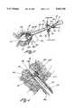
- FIG. 1is a front elevational view showing the continuous flow cystoscope which is fully assembled and which has a telescope located in the inner member first passageway and which has a side firing laser inserted into the inner member second passageway;
- FIG. 2ais a front elevational view of the outer sheath showing the elongated fenestra located at the distal end of the outer sheath, the inlet port, the outlet port and the first connecting means located at the proximal end of the outer sheath;
- FIG. 2bis a front elevational view of the means defining the inner member showing the inner member having a second connecting means, means defining the first passageway, means defining the second passageway and means defining the irrigation inlet and the elongated lip located at the distal end of the inner member;
- FIG. 3is a left end elevational view of the distal end of the continuous flow cystoscope showing the telescope distal end, the laser fiber, irrigation inlet and irrigation outlet;
- FIG. 4is a partial cross sectional view of the distal end of the continuous flow cystoscope showing the fluid flow from the irrigation inlet of the inner member past the distal end of the telescope and the working tool and into the irrigating outlet of the fenestra channel;
- FIG. 5is a pictorial representation of the continuous flow cystoscope performing an incision, excision, ablation and hemostasis of the lower genitourinary tract including prostatic tissue procedure;
- FIG. 6is another pictorial representation showing the relationship between the elongated fenestra and the side firing laser.
- FIG. 1illustrates an instrument generally as 18, which, in the preferred embodiment is a continuous flow cystoscope.
- the continuous flow cystoscope 18is adapted to be utilized for performing therapeutic procedures in the urinary tract, and in particular, in the prostatic urethra and bladder cavity.
- outletany orifice, channel, port or opening through which fluid enters the operative site or cavity.
- the instrument 18includes a means 20 for defining an outer sheath 22 having a distal section 30 and means for defining an opening 28.
- the distal section 30 of the outer sheath 22includes a means for defining an elongated fenestra 32 which extends along a predetermined path relative to the distal section 30.
- the outer sheath 22has an elongated central axis and the elongated fenestra 30 extends along a predetermined path which is substantially parallel relative to the central axis.
- the outer sheath 22further includes a proximal end 24 which includes a first connecting means 40, which has an inlet port 44 and an outlet port 46.
- FIG. 1further depicts that the continuous flow cystoscope 18 includes a means 50 defining an inner member 58 (see FIG. 2b) having an inner member channel 78 (see FIG. 2b), which is positioned within the means defining the outer sheath 20.
- the means 50 defining the inner member 58when positioned within the outer sheath 22, forms a fluid passageway therebetween.
- the inner member defining means 50includes means for defining a telescope guide tube 74, which has an opening 76 at one end thereof which is adapted to receive a telescope shown generally as 70.
- the telescope guide tube 74is operatively connected to a second connecting means 54 and communicates with the inner member channel 78 which is an open, oblong shaped channel.
- the inner member channel 78defines a passageway which is adapted to receive a telescope to pass a working tool.
- the telescopeincludes a light post 78 which is adapted to have a light carrier affixed thereto and includes an eyepiece 80 with an opening 82 to enable the cystoscope to be viewed directly by a surgeon or to have a video camera affixed thereto.
- the means 50 defining the inner member 78includes a working tool guide tube 60 includes an opening 62 which is adapted to pass a working tool such as a laser fiber at 90.
- the laser fiber at 90is passed through the working tool guide tool 60 into the inner member channel 78 and is advanced sufficiently through the inner member channel 78 such that the distal end of the laser 92 having a lasing surface 94 is passed distally through the opening 28 and positioned relative to the distal end of the telescope 80.
- the surgeoncan view the position of the laser tip 94 through the distal end of the telescope 28.
- the elongated fenestra 32is positioned to protect the non-lasing surface of the laser tip 94 to prevent the same from contacting other tissue.
- the long fenestra 32cooperates with an elongated lip, shown as elongated lip 104 in FIG. 2b, of the means 50 defining an inner member 58 to form a fenestra channel.
- the fenestra channel 36which includes an irrigation inlet shown as 34 in FIG. 1.
- FIG. 2ashows the details of the outer sheath 22.
- the distal section 30terminates in an elongated fenestra 32 having a shaped tip in the form of a raised smooth member.
- the shape of the tipis illustrated in greater detail in FIG. 4.
- the shape tip of the fenestrais selected so as to reduce trauma when the distal end of the cystoscope is inserted into the urethra and advanced to position the distal end of the cystoscope at a predetermined location within the urethra.
- the distal end of the continuous flow cystoscopewould be advanced within the urethra of a male until the distal end thereof is positioned relative to the prostate where the for the incision, excision, ablation and hemostasis of the lower genitourinary tract including prostatic tissue procedure is to be performed.
- the outer sheath 22is shown to include the first connecting means 40 which includes an inlet port 44 and the outlet port 46.
- the first connecting means 40includes an insertion member 96 which is adapted to releasably connect to the second connecting means 54 located on the means 50 defining the inner member 58 as illustrated in FIG. 2b.
- FIG. 2aalso illustrates that opening 28 is formed at an acute angle relative to the central axis. This may be referred to as a slanted opening.
- the openinghas an oblong shape as illustrated by opening 28 in FIG. 3.
- FIG. 2billustrates in greater detail the structure of the means defining the inner member 58.
- the means 50 defining the inner member 58includes a distal section 100.
- the distal section 100includes means for defining an irrigation inlet 140 and an elongated lip 104 which has a protrusion section 106 formed therein which is substantially triangular in shape.
- the irrigation inlet 140is slanted in the same manner as that of the opening 28. In the preferred embodiment, the opening 28 and irrigation inlet 140 are substantially coplaner.
- the elongated lip 104having the protrusion 106 which cooperates with the elongated fenestra 32 of the outer sheath 22 to form the irrigation outlet 34 and the fenestra channel 36.
- the fenestra channel 36is illustrated in FIG. 4.
- the fenestra channel 36 and irrigation outlet 34are located at the distal end of the fenestra 32 and elongated lip 104 location.
- FIG. 2balso illustrates that the proximal end of the inner member 58 includes a second connecting means shown generally as 54 which cooperates with a spring loaded latch 56 to removeably connect the second connecting means 54 to the first connecting means 40 of the outer sheath 22.
- the second connecting means 54includes a raised boss having a groove 108 which defines an inlet channel which cooperates with one or more inlet openings 110 which are adapted to cooperate with the inlet port 44 located in FIG. 2a. Irrigation fluid will flow through the inlet port 44 to the inlet opening 110 which passes the fluid into the inner member channel 78.
- the outlet port 46is operatively coupled through an outlet channel internal to the first connecting means 24 to the fluid passageway defined being the outer sheath 20 and inner member 50.
- FIG. 2billustrates that the telescope guide tube 74 terminates in a housing 76 which is adapted to receive and support the telescope 70 as illustrated in FIG. 1.
- the working tool guide tube 60includes an opening 62 which is adapted to pass a working tool, such as, for example, a side firing laser fiber.
- Each of the telescope guide tube 74 and the working tool guide tube 60terminates in the second connecting means 54 and the ends thereof communicate with the inner member channel 78.
- the telescope guide tube 74cooperates with the first passageway of the inner member channel 78 to pass the telescope 80.
- the working tool guide tube 60cooperates with the second passageway of the inner member channel 78 to pass the working tool 90.
- FIG. 3illustrates in detail the structural arrangement of the assembled continuous flow cystoscope.
- the outer sheath 22terminates in the fenestra 32 and defines an opening 28.
- the distal end opening of the inner member 58defines the irrigation inlet 140.
- the means 50 defining the inner member 58includes means for defining the inner-member channel 78 having on the upper section thereof the first passageway which is adapted to receive the telescope 80 having distal end 86 having on the lower section thereof a second passageway which is adapted to receive the laser fiber 92.
- the irrigation inlet 140 and the distal end of the inner member 58are located within the opening 28 of the outer sheath 22.
- the distal end 100 of the inner member 58terminates in the elongated lip 104 having the protrusion 106 formed thereon.
- the elongated lip 104cooperates with the elongated fenestra 32 to define the irrigation outlet 34 and the fenestra channel 36.
- FIG. 4illustrates in greater detail the structural and operative relationship between the outer sheath 22 and the inner member 58.
- the outer sheath 22has its distal end 30 illustrated in the form of an elongated fenestra 32 having a shaped tip at the end thereof to facilitate atraumatic insertion of the distal end of the cystoscope into the urethra.
- the outer sheath 22includes means for defining an opening 28. The opening 28 is sized to receive the distal end 100 of the inner member 58 including the irrigation inlet 140.
- FIG. 4illustrates that the distal end of the telescope 86 has a viewing lens 84 positioned in the vicinity of the irrigation inlet 140 in the distal end 100.
- the working toolwhich in the preferred embodiment is a side firing laser fiber, has a distal laser fiber end 92 which terminates in a lasing surface 94.
- the non-lasing surfaceis spaced from and protected by the elongated fenestra 32.
- FIG. 4illustrates by means of arrows 112 the fluid flow of irrigation fluid.
- the irrigation fluidpasses through the inner member channel 78 including the first passageway and second passageway and passes out the irrigation inlet 140.
- the fluid flowmaintains a relatively linear direction of movement as it passes from the irrigation inlet 140 past the distal end 86 of the telescope 70 including the lens surface 84 thereof, past the laser fiber distal section 92 including the lasing surface 94 to the distal end of the elongated fenestra 32 where the fluid is then drawn into the irrigation outlet 34 and into the fenestra channel 36 and through the fluid passageway 120.
- the fluid flow pathis such that there is reduced turbulence in the vicinity of the telescope lens 84 in that image impeding materials, such as blood or tissue, are immediately removed by the linear flow of irrigation fluid away from the viewing means 84 and towards the fenestra channel 36 for removal.
- FIG. 5illustrates a method for performing a procedure utilizing the continuous flow cystoscope of the present invention.
- the continuous flow cystoscope 18has been inserted through the urethra 206 of the penis 200 of a male into the area of the prostate shown generally as 210 which is located beyond the testicles 208.
- the proximal end 24 of the outer sheath 22has the inlet port 44 operatively connected to a source of irrigation fluid under positive pressure.
- the outlet port 46is illustrated as being operatively connected to a negative pressure.
- a laser fiber 90is shown in position in the working tool guide tube 60 and the distal end 92 of the laser fiber 90 having the lasing surface 94 is likewise illustrated.
- the outer sheath 22is passed through the urethra 206 of the penis 200 and past the testicles 208 into the area of the prostate illustrated as 210.
- the elongated fenestra 32is shown supporting the opposite side of the prostate in a position to enable the urologist to specifically identify an operative site in the prostate 210 for the incision, excision, ablation and hemostasis of the lower genitourinary tract including prostatic tissue.
- the laser fiber 90is actuated to produce the laser radiation shown generally as 214 to necrosis the tissue.
- FIG. 6illustrates in a pictorial representation the distal tip structure wherein the opening 28 of the outer sheath 22 encloses the distal section 100 of the inner member 58 and the irrigation opening 140.
- the elongated lip 104cooperates with the elongated fenestra 32 to define the irrigation outlet 34 and fenestra channel 36 to establish the generally linear fluid flow as illustrated in FIG. 4.
- FIG. 5 and 6illustrate a method for performing a medical procedure comprising the steps of assembling an instrument 20 comprising means defining an outer sheath 22 having an outer surface and a hollowed out central area where the outer sheath 22 has a proximal section 24 and a distal section 30 wherein the distal section 30 includes means for defining an opening 28 which communicates with the hollowed out central area and means for defining an elongated fenestra 32 and means 50 defining an inner member 58 positioned within the hollowed out central area of the outer sheath 22 and the means 50 defining the inner member 58 includes means for defining a distal end 100 and means for defining an irrigation inlet 140 wherein the distal end 100 and the irrigation inlet 140 are positioned within the opening 28 and the elongated lip 104 wherein the inner member forms a fluid passageway 120 which communicates with the fenestra channel 34 formed between the outer sheath 22 and the inner member 58 and wherein the elongated fenestra 30
- FIGS. 5 and 6would then require the step of applying an irrigating fluid, as illustrated in FIG. 4, to an inlet port 44 located at the proximal section of the outer sheath 22 which is operatively coupled to the inner member channel 78 for passing the irrigation fluid therethrough and out the irrigation inlet 140.
- the step of applying an irrigation fluid to the inlet and passing irrigation fluid shown by arrows 110 through the inner member channel 78 and around the side firing laser fiber 94cools the laser fiber and concurrently irrigates the operative site.
- the preferred embodiment of the present inventionis as a continuous flow laser cystoscope.
- the continuous flow laser cystoscopecan be utilized for performing both diagnostic and therapeutic procedures in the urinary tract.
- One application for the present applicationis in the incision, excision, ablation and hemostasis of the lower genitourinary tract including prostatic tissue for male patients.
- the urologistcan utilize the continuous flow cystoscope together with a side firing laser to visually and precisely control necrosis of the prostate tissue and to insure that the laser tip is properly cooled during the procedure.
- the fluid flow pathis such that image impeding material in the form of tissue or blood which would otherwise impede visualization of the surgeon is continually removed in a direction away from the viewing means, thereby reducing fluid turbulence and thereby providing an unobstructed flow of irrigation fluid across the irrigation site.
- the same principlescan be utilized in a continuous flow resectoscope for performing other surgical procedures or can be utilized as a continuous flow hysteroscope for performing gynecological procedures.
- fluid flow in a continuous flow hysteroscopecould be precisely controlled to insure that a predetermined pressure limit is not exceeded.
- the irrigation flow through the continuous flow instrumentcould be controlled by gravity such as from a bag of saline fluid supported from an I.V. stand or positive fluid flow could be effected by an input pump or output pump or both which could be precisely controlled.
Landscapes
- Health & Medical Sciences (AREA)
- Life Sciences & Earth Sciences (AREA)
- Surgery (AREA)
- Engineering & Computer Science (AREA)
- Heart & Thoracic Surgery (AREA)
- Nuclear Medicine, Radiotherapy & Molecular Imaging (AREA)
- Optics & Photonics (AREA)
- Pathology (AREA)
- Radiology & Medical Imaging (AREA)
- Physics & Mathematics (AREA)
- Urology & Nephrology (AREA)
- Biomedical Technology (AREA)
- Biophysics (AREA)
- Medical Informatics (AREA)
- Molecular Biology (AREA)
- Animal Behavior & Ethology (AREA)
- General Health & Medical Sciences (AREA)
- Public Health (AREA)
- Veterinary Medicine (AREA)
- Laser Surgery Devices (AREA)
- Endoscopes (AREA)
Abstract
Description
Claims (16)
Priority Applications (2)
| Application Number | Priority Date | Filing Date | Title |
|---|---|---|---|
| US08/017,475US5392765A (en) | 1993-02-11 | 1993-02-11 | Continuous flow cystoscope |
| US08/344,559US5549541A (en) | 1993-02-11 | 1994-11-23 | Continuous flow cystoscope |
Applications Claiming Priority (1)
| Application Number | Priority Date | Filing Date | Title |
|---|---|---|---|
| US08/017,475US5392765A (en) | 1993-02-11 | 1993-02-11 | Continuous flow cystoscope |
Related Child Applications (1)
| Application Number | Title | Priority Date | Filing Date |
|---|---|---|---|
| US08/344,559ContinuationUS5549541A (en) | 1993-02-11 | 1994-11-23 | Continuous flow cystoscope |
Publications (1)
| Publication Number | Publication Date |
|---|---|
| US5392765Atrue US5392765A (en) | 1995-02-28 |
Family
ID=21782792
Family Applications (2)
| Application Number | Title | Priority Date | Filing Date |
|---|---|---|---|
| US08/017,475Expired - LifetimeUS5392765A (en) | 1993-02-11 | 1993-02-11 | Continuous flow cystoscope |
| US08/344,559Expired - LifetimeUS5549541A (en) | 1993-02-11 | 1994-11-23 | Continuous flow cystoscope |
Family Applications After (1)
| Application Number | Title | Priority Date | Filing Date |
|---|---|---|---|
| US08/344,559Expired - LifetimeUS5549541A (en) | 1993-02-11 | 1994-11-23 | Continuous flow cystoscope |
Country Status (1)
| Country | Link |
|---|---|
| US (2) | US5392765A (en) |
Cited By (66)
| Publication number | Priority date | Publication date | Assignee | Title |
|---|---|---|---|---|
| US5807240A (en)* | 1996-09-24 | 1998-09-15 | Circon Corporation | Continuous flow endoscope with enlarged outflow channel |
| US5827216A (en)* | 1995-06-07 | 1998-10-27 | Cormedics Corp. | Method and apparatus for accessing the pericardial space |
| US6402715B2 (en)* | 1996-04-25 | 2002-06-11 | Karl Storz Gmbh & Co. Kg | Surgical instrument system |
| US6572631B1 (en)* | 1993-10-22 | 2003-06-03 | Gynetech Pty Ltd. | Transvaginal tube as an aid to laparoscopic surgery |
| US6712759B2 (en) | 2002-01-07 | 2004-03-30 | Acmi Corporation | Outflow system for an endoscope |
| US20050085695A1 (en)* | 2003-10-16 | 2005-04-21 | Cemal Shener | Endoscopic device |
| US20050107665A1 (en)* | 2003-11-18 | 2005-05-19 | Nady Nady E. | Device for sealing a body canal and method of use |
| US20060047185A1 (en)* | 2004-08-27 | 2006-03-02 | Cemal Shener | Tissue resecting system |
| US7249602B1 (en) | 1997-09-04 | 2007-07-31 | Smith & Nephew, Inc. | Surgical endoscopic cutting device and method for its use |
| EP1911390A1 (en) | 2006-10-11 | 2008-04-16 | Alka Kumar | Efficient continuous flow irrigation endoscope |
| US20080091061A1 (en)* | 2006-10-11 | 2008-04-17 | Alka Kumar | Efficient continuous flow irrigation system |
| US20080091071A1 (en)* | 2006-10-11 | 2008-04-17 | Alka Kumar | System for evacuating detached tissue in continuous flow irrigation endoscopic procedures |
| US20080097468A1 (en)* | 2006-10-18 | 2008-04-24 | Adams Ronald D | Systems for performing gynecological procedures with closed visualization lumen |
| US20080146872A1 (en)* | 2006-11-07 | 2008-06-19 | Gruber William H | Mechanical distension systems for performing a medical procedure in a remote space |
| US20080249366A1 (en)* | 2007-04-06 | 2008-10-09 | William Harwick Gruber | System for use in performing a medical procedure and introducer device suitable for use in said system |
| US20080249553A1 (en)* | 2007-04-06 | 2008-10-09 | William Harwick Gruber | Method, system and device for tissue removal |
| US20090270896A1 (en)* | 2007-04-06 | 2009-10-29 | Interlace Medical, Inc. | Tissue cutter with differential hardness |
| US20090270898A1 (en)* | 2007-04-06 | 2009-10-29 | Interlace Medical, Inc. | Tissue removal device with high reciprocation rate |
| US7794393B2 (en) | 2006-04-13 | 2010-09-14 | Larsen Dane M | Resectoscopic device and method |
| US20110118544A1 (en)* | 2009-11-13 | 2011-05-19 | Interlace Medical, Inc. | Access system with removable outflow channel |
| US20110230904A1 (en)* | 2001-10-26 | 2011-09-22 | Smith & Nephew, Inc. | Reciprocating rotary arthroscopic surgical instrument |
| US8025656B2 (en) | 2006-11-07 | 2011-09-27 | Hologic, Inc. | Methods, systems and devices for performing gynecological procedures |
| US20110295066A1 (en)* | 2010-05-28 | 2011-12-01 | Gyrus Acmi, Inc. | Continuous flow endoscope systems |
| US20120277721A1 (en)* | 2001-10-12 | 2012-11-01 | Hauschild Sidney F | Surgical instrument for injecting a drug into prostate tissue |
| USD682423S1 (en)* | 2010-12-23 | 2013-05-14 | Karl Storz Gmbh & Co. Kg | Resectoscope sheath |
| US9155454B2 (en) | 2010-09-28 | 2015-10-13 | Smith & Nephew, Inc. | Hysteroscopic system |
| EP3028623A1 (en)* | 2014-12-05 | 2016-06-08 | Karl Storz GmbH & Co. KG | Endoscopic instrument and endoscopic instrument system |
| US10178942B2 (en) | 2015-08-27 | 2019-01-15 | Boston Scientific Scimed, Inc. | Fluid management systems and methods |
| US10299819B2 (en) | 2016-07-28 | 2019-05-28 | Covidien Lp | Reciprocating rotary surgical cutting device and system for tissue resecting, and method for its use |
| US10299803B2 (en) | 2016-08-04 | 2019-05-28 | Covidien Lp | Self-aligning drive coupler |
| US10537227B2 (en) | 2015-08-27 | 2020-01-21 | Boston Scientific Scimed, Inc. | Medical devices and methods |
| US10631889B2 (en) | 2014-12-16 | 2020-04-28 | Covidien Lp | Surgical device with incorporated tissue extraction |
| US10750931B2 (en) | 2015-05-26 | 2020-08-25 | Covidien Lp | Systems and methods for generating a fluid bearing for an operative procedure |
| US10772652B2 (en) | 2015-01-28 | 2020-09-15 | Covidien Lp | Tissue resection system |
| US10772654B2 (en) | 2017-03-02 | 2020-09-15 | Covidien Lp | Fluid-driven tissue resecting instruments, systems, and methods |
| US10804769B2 (en) | 2015-06-17 | 2020-10-13 | Covidien Lp | Surgical instrument with phase change cooling |
| US10799264B2 (en) | 2015-06-18 | 2020-10-13 | Covidien Lp | Surgical instrument with suction control |
| US10842350B2 (en) | 2015-06-17 | 2020-11-24 | Covidien Lp | Endoscopic device with drip flange and methods of use thereof for an operative procedure |
| US10869684B2 (en) | 2018-02-13 | 2020-12-22 | Covidien Lp | Powered tissue resecting device |
| CN112120662A (en)* | 2020-10-17 | 2020-12-25 | 陈锦瑞 | Bladder stone lithotripsy |
| US10898218B2 (en) | 2019-02-25 | 2021-01-26 | Covidien Lp | Tissue resecting device including a motor cooling assembly |
| US10945752B2 (en) | 2019-03-20 | 2021-03-16 | Covidien Lp | Tissue resecting instrument including a rotation lock feature |
| US11065147B2 (en) | 2018-10-18 | 2021-07-20 | Covidien Lp | Devices, systems, and methods for pre-heating fluid to be introduced into a patient during a surgical procedure |
| US11083481B2 (en) | 2019-02-22 | 2021-08-10 | Covidien Lp | Tissue resecting instrument including an outflow control seal |
| US11154318B2 (en) | 2019-02-22 | 2021-10-26 | Covidien Lp | Tissue resecting instrument including an outflow control seal |
| US11179172B2 (en) | 2019-12-05 | 2021-11-23 | Covidien Lp | Tissue resecting instrument |
| US11197710B2 (en) | 2018-10-26 | 2021-12-14 | Covidien Lp | Tissue resecting device including a blade lock and release mechanism |
| US20220125288A1 (en)* | 2020-10-28 | 2022-04-28 | Medtronic Xomed, Inc. | Lavage and Cleansing System and Method |
| US11317947B2 (en) | 2020-02-18 | 2022-05-03 | Covidien Lp | Tissue resecting instrument |
| US11376032B2 (en) | 2019-12-05 | 2022-07-05 | Covidien Lp | Tissue resecting instrument |
| US11452806B2 (en) | 2019-10-04 | 2022-09-27 | Covidien Lp | Outflow collection vessels, systems, and components thereof for hysteroscopic surgical procedures |
| US11547815B2 (en) | 2018-05-30 | 2023-01-10 | Covidien Lp | Systems and methods for measuring and controlling pressure within an internal body cavity |
| US11547782B2 (en) | 2020-01-31 | 2023-01-10 | Covidien Lp | Fluid collecting sheaths for endoscopic devices and systems |
| US11553977B2 (en) | 2019-05-29 | 2023-01-17 | Covidien Lp | Hysteroscopy systems and methods for managing patient fluid |
| US20230026445A1 (en)* | 2015-02-27 | 2023-01-26 | Covidien Lp | Oblique tip endoscope with zero degree field angle |
| US11571233B2 (en) | 2020-11-19 | 2023-02-07 | Covidien Lp | Tissue removal handpiece with integrated suction |
| US11596429B2 (en) | 2020-04-20 | 2023-03-07 | Covidien Lp | Tissue resecting instrument |
| US11737777B2 (en) | 2020-02-05 | 2023-08-29 | Covidien Lp | Tissue resecting instruments |
| US11864735B2 (en) | 2016-05-26 | 2024-01-09 | Covidien Lp | Continuous flow endoscope |
| US11883058B2 (en) | 2019-03-26 | 2024-01-30 | Covidien Lp | Jaw members, end effector assemblies, and ultrasonic surgical instruments including the same |
| US11890237B2 (en) | 2019-10-04 | 2024-02-06 | Covidien Lp | Outflow collection vessels, systems, and components thereof for hysteroscopic surgical procedures |
| US11903602B2 (en) | 2009-04-29 | 2024-02-20 | Hologic, Inc. | Uterine fibroid tissue removal device |
| US11957406B2 (en) | 2015-08-27 | 2024-04-16 | Minerva Surgical, Inc. | Tissue resecting device and methods |
| US12156673B2 (en) | 2020-10-07 | 2024-12-03 | Covidien Lp | Temperature measurement device for a handpiece of a surgical instrument |
| US12303109B2 (en) | 2021-12-22 | 2025-05-20 | Covidien Lp | Surgical systems and methods for component cooling while warming fluid to be introduced during a surgical procedure |
| US12364500B2 (en) | 2021-05-26 | 2025-07-22 | Covidien Lp | Tissue resecting instrument |
Families Citing this family (17)
| Publication number | Priority date | Publication date | Assignee | Title |
|---|---|---|---|---|
| DE19780707C2 (en)* | 1996-03-22 | 2002-09-12 | Sdgi Holdings Inc | Percutaneous surgery device |
| US6712757B2 (en)* | 2001-05-16 | 2004-03-30 | Stephen Becker | Endoscope sleeve and irrigation device |
| US7141035B2 (en)* | 2003-03-28 | 2006-11-28 | Sherwood Services Ag | Catheter with occlusion resistant tip |
| US7776005B2 (en)* | 2003-03-28 | 2010-08-17 | Covidien Ag | Triple lumen catheter with occlusion resistant tip |
| US7090654B2 (en)* | 2003-03-28 | 2006-08-15 | Sherwood Services Ag | Catheter with occlusion resistant tip |
| JP4873748B2 (en) | 2004-11-04 | 2012-02-08 | コヴィディエン・アクチェンゲゼルシャフト | Catheter insertion device |
| DE102009015392A1 (en)* | 2009-03-20 | 2010-09-23 | Karl Storz Gmbh & Co. Kg | Medical instrument, in particular hysteroscope |
| EP3241585B1 (en) | 2009-06-26 | 2019-01-02 | Covidien LP | Catheterization system |
| US20100331621A1 (en)* | 2009-06-30 | 2010-12-30 | Gyrus Acmi, Inc. | Bipolar resection device having simplified rotational control and better visualization |
| CA2715857A1 (en) | 2009-09-30 | 2011-03-30 | Tyco Healthcare Group Lp | Medical catheter having a design providing low recirculation and reversibility |
| CN101940466A (en)* | 2010-09-15 | 2011-01-12 | 黄永斌 | Obturator of cystoscope |
| JP2012065861A (en) | 2010-09-24 | 2012-04-05 | Nihon Covidien Kk | Dialysis catheter |
| USD667547S1 (en)* | 2011-03-31 | 2012-09-18 | Karl Storz Gmbh & Co. Kg | Medical device |
| US8747343B2 (en) | 2011-09-30 | 2014-06-10 | Covidien Lp | Hemodialysis catheter with improved side opening design |
| US9072867B2 (en) | 2011-09-30 | 2015-07-07 | Covidien Lp | Catheter with external flow channel |
| US9155862B2 (en) | 2012-09-28 | 2015-10-13 | Covidien Lp | Symmetrical tip acute catheter |
| DE102021132986A1 (en)* | 2021-12-13 | 2023-06-15 | Olympus Winter & Ibe Gmbh | Surgical handpiece and shaft for a surgical handpiece |
Citations (6)
| Publication number | Priority date | Publication date | Assignee | Title |
|---|---|---|---|---|
| US2076741A (en)* | 1935-04-09 | 1937-04-13 | American Cystoscope Makers Inc | Fenestrated endoscopic tube |
| US3835842A (en)* | 1972-07-03 | 1974-09-17 | J Iglesias | Endoscope with continuous irrigation |
| US3850175A (en)* | 1972-07-03 | 1974-11-26 | J Lglesias | Resectoscope with continuous irrigation |
| US5031603A (en)* | 1989-04-19 | 1991-07-16 | Richard Wolf Gmbh | Uretero-renoscope |
| US5095889A (en)* | 1989-05-31 | 1992-03-17 | Richard Wolf Gmbh | Endoscope for laser lithotripsy |
| US5151101A (en)* | 1988-06-02 | 1992-09-29 | Circon Corporation | System for disconnectably mounting an endoscope sheath with an endoscope tool |
Family Cites Families (4)
| Publication number | Priority date | Publication date | Assignee | Title |
|---|---|---|---|---|
| US3939839A (en)* | 1974-06-26 | 1976-02-24 | American Cystoscope Makers, Inc. | Resectoscope and electrode therefor |
| US4132227A (en)* | 1974-08-08 | 1979-01-02 | Winter & Ibe | Urological endoscope particularly resectoscope |
| US4423727A (en)* | 1981-04-10 | 1984-01-03 | Jerrold Widran | Continuous flow urological endoscopic apparatus and method of using same |
| US5037386A (en)* | 1989-11-17 | 1991-08-06 | Minnesota Mining And Manufacturing Company | Pressure sensing scope cannula |
- 1993
- 1993-02-11USUS08/017,475patent/US5392765A/ennot_activeExpired - Lifetime
- 1994
- 1994-11-23USUS08/344,559patent/US5549541A/ennot_activeExpired - Lifetime
Patent Citations (6)
| Publication number | Priority date | Publication date | Assignee | Title |
|---|---|---|---|---|
| US2076741A (en)* | 1935-04-09 | 1937-04-13 | American Cystoscope Makers Inc | Fenestrated endoscopic tube |
| US3835842A (en)* | 1972-07-03 | 1974-09-17 | J Iglesias | Endoscope with continuous irrigation |
| US3850175A (en)* | 1972-07-03 | 1974-11-26 | J Lglesias | Resectoscope with continuous irrigation |
| US5151101A (en)* | 1988-06-02 | 1992-09-29 | Circon Corporation | System for disconnectably mounting an endoscope sheath with an endoscope tool |
| US5031603A (en)* | 1989-04-19 | 1991-07-16 | Richard Wolf Gmbh | Uretero-renoscope |
| US5095889A (en)* | 1989-05-31 | 1992-03-17 | Richard Wolf Gmbh | Endoscope for laser lithotripsy |
Cited By (153)
| Publication number | Priority date | Publication date | Assignee | Title |
|---|---|---|---|---|
| US20050261714A1 (en)* | 1993-10-22 | 2005-11-24 | Mccartney Anthony J | Transvaginal tube as an aid to laparoscopic surgery |
| US8082925B2 (en) | 1993-10-22 | 2011-12-27 | Gynetech Pty Ltd. | Transvaginal tube as an aid to laparoscopic surgery |
| US20070112356A1 (en)* | 1993-10-22 | 2007-05-17 | Gynetech Pty Ltd | Transvaginal tube as an aid to laparoscopic surgery |
| US6572631B1 (en)* | 1993-10-22 | 2003-06-03 | Gynetech Pty Ltd. | Transvaginal tube as an aid to laparoscopic surgery |
| US6666844B1 (en) | 1995-06-07 | 2003-12-23 | Stephen R. Igo | Method and apparatus for accessing the pericardial space |
| US5827216A (en)* | 1995-06-07 | 1998-10-27 | Cormedics Corp. | Method and apparatus for accessing the pericardial space |
| US6402715B2 (en)* | 1996-04-25 | 2002-06-11 | Karl Storz Gmbh & Co. Kg | Surgical instrument system |
| US5807240A (en)* | 1996-09-24 | 1998-09-15 | Circon Corporation | Continuous flow endoscope with enlarged outflow channel |
| US8061359B2 (en) | 1997-09-04 | 2011-11-22 | Smith & Nephew, Inc. | Surgical endoscopic cutting device and method for its use |
| US9226650B2 (en) | 1997-09-04 | 2016-01-05 | Smith & Nephew, Inc. | Surgical cutting device and method for its use |
| US9226765B2 (en) | 1997-09-04 | 2016-01-05 | Smith & Nephew, Inc. | Surgical cutting device and method for its use |
| US9427247B2 (en) | 1997-09-04 | 2016-08-30 | Smith & Nephew, Inc. | Surgical cutting device and method for its use |
| US7249602B1 (en) | 1997-09-04 | 2007-07-31 | Smith & Nephew, Inc. | Surgical endoscopic cutting device and method for its use |
| US20080015621A1 (en)* | 1997-09-04 | 2008-01-17 | Smith & Nephew, Inc. | Surgical endoscopic cutting device and method for its use |
| US20080058588A1 (en)* | 1997-09-04 | 2008-03-06 | Smith & Nephew, Inc. | Surgical endoscopic cutting device and method for its use |
| US9089358B2 (en) | 1997-09-04 | 2015-07-28 | Smith & Nephew, Inc. | Surgical cutting device and method for its use |
| US8893722B2 (en) | 1997-09-04 | 2014-11-25 | Smith & Nephew, Inc. | Surgical endoscopic cutting device and method for its use |
| US9750520B2 (en) | 1997-09-04 | 2017-09-05 | Covidien Lp | Surgical endoscopic cutting device and method for its use |
| US9782547B2 (en) | 2001-10-12 | 2017-10-10 | Boston Scientific Scimed, Inc. | Methods for injecting a drug into prostate tissue |
| US20120277721A1 (en)* | 2001-10-12 | 2012-11-01 | Hauschild Sidney F | Surgical instrument for injecting a drug into prostate tissue |
| US8992465B2 (en)* | 2001-10-12 | 2015-03-31 | Ams Research Corporation | Surgical instrument for injecting a drug into prostate tissue |
| US9636130B2 (en) | 2001-10-26 | 2017-05-02 | Covidien Lp | Reciprocating rotary arthroscopic surgical instrument |
| US9066745B2 (en) | 2001-10-26 | 2015-06-30 | Smith & Nephew, Inc. | Reciprocating rotary arthroscopic surgical instrument |
| US9060800B1 (en) | 2001-10-26 | 2015-06-23 | Smith & Nephew, Inc. | Reciprocating rotary arthroscopic surgical instrument |
| US9060801B1 (en) | 2001-10-26 | 2015-06-23 | Smith & Nephew, Inc. | Reciprocating rotary arthroscopic surgical instrument |
| US10441306B2 (en) | 2001-10-26 | 2019-10-15 | Covidien Lp | Reciprocating rotary arthroscopic surgical instrument |
| US20110230904A1 (en)* | 2001-10-26 | 2011-09-22 | Smith & Nephew, Inc. | Reciprocating rotary arthroscopic surgical instrument |
| US8663264B2 (en) | 2001-10-26 | 2014-03-04 | Smith & Nephew, Inc. | Reciprocating rotary arthroscopic surgical instrument |
| US6712759B2 (en) | 2002-01-07 | 2004-03-30 | Acmi Corporation | Outflow system for an endoscope |
| US20050085695A1 (en)* | 2003-10-16 | 2005-04-21 | Cemal Shener | Endoscopic device |
| US7150713B2 (en) | 2003-10-16 | 2006-12-19 | Smith & Nephew, Inc. | Endoscopic device |
| US20050107665A1 (en)* | 2003-11-18 | 2005-05-19 | Nady Nady E. | Device for sealing a body canal and method of use |
| US8852085B2 (en) | 2004-08-27 | 2014-10-07 | Smith & Nephew, Inc. | Tissue resecting system |
| US8062214B2 (en) | 2004-08-27 | 2011-11-22 | Smith & Nephew, Inc. | Tissue resecting system |
| US9125550B2 (en) | 2004-08-27 | 2015-09-08 | Smith & Nephew, Inc. | Tissue resecting system |
| US9936861B2 (en) | 2004-08-27 | 2018-04-10 | Covidien Lp | Tissue resecting system |
| US20060047185A1 (en)* | 2004-08-27 | 2006-03-02 | Cemal Shener | Tissue resecting system |
| US10939810B2 (en) | 2004-08-27 | 2021-03-09 | Covidien Lp | Tissue resecting system |
| US10076237B2 (en) | 2004-08-27 | 2018-09-18 | Covidien Lp | Tissue resecting system |
| US8419626B2 (en) | 2004-08-27 | 2013-04-16 | Smith & Nephew, Inc. | Tissue resecting system |
| US20100312053A1 (en)* | 2006-04-13 | 2010-12-09 | Larsen Dane M | Resectoscopic device and method |
| US7794393B2 (en) | 2006-04-13 | 2010-09-14 | Larsen Dane M | Resectoscopic device and method |
| US9028398B2 (en) | 2006-10-11 | 2015-05-12 | Alka Kumar | System for evacuating detached tissue in continuous flow irrigation endoscopic procedures |
| US8226549B2 (en) | 2006-10-11 | 2012-07-24 | Alka Kumar | Efficient continuous flow irrigation system |
| US20080091071A1 (en)* | 2006-10-11 | 2008-04-17 | Alka Kumar | System for evacuating detached tissue in continuous flow irrigation endoscopic procedures |
| US10028763B2 (en) | 2006-10-11 | 2018-07-24 | Alka Kumar | Efficient continuous flow irrigation endoscope |
| EP1911390A1 (en) | 2006-10-11 | 2008-04-16 | Alka Kumar | Efficient continuous flow irrigation endoscope |
| US20080091074A1 (en)* | 2006-10-11 | 2008-04-17 | Alka Kumar | Efficient continuous flow irrigation endoscope |
| US8911363B2 (en) | 2006-10-11 | 2014-12-16 | Alka Kumar | Efficient continuous flow irrigation system |
| US9155453B2 (en) | 2006-10-11 | 2015-10-13 | Alka Kumar | Efficient continuous flow irrigation endoscope |
| US20080091061A1 (en)* | 2006-10-11 | 2008-04-17 | Alka Kumar | Efficient continuous flow irrigation system |
| US8840625B2 (en) | 2006-10-18 | 2014-09-23 | Hologic, Inc. | Systems for performing gynecological procedures with closed visualization lumen |
| US20080097468A1 (en)* | 2006-10-18 | 2008-04-24 | Adams Ronald D | Systems for performing gynecological procedures with closed visualization lumen |
| US20110054488A1 (en)* | 2006-10-18 | 2011-03-03 | Gruber William H | Systems and methods for preventing intravasation during intrauterine procedures |
| US8840626B2 (en) | 2006-10-18 | 2014-09-23 | Hologic, Inc. | Systems for performing gynecological procedures with simultaneous tissue cutting and removal |
| US8834487B2 (en) | 2006-10-18 | 2014-09-16 | Hologic, Inc. | Systems and methods for preventing intravasation during intrauterine procedures |
| US20080097471A1 (en)* | 2006-10-18 | 2008-04-24 | Adams Ronald D | Systems for performing gynecological procedures with simultaneous tissue cutting and removal |
| US8647349B2 (en) | 2006-10-18 | 2014-02-11 | Hologic, Inc. | Systems for performing gynecological procedures with mechanical distension |
| US9392935B2 (en) | 2006-11-07 | 2016-07-19 | Hologic, Inc. | Methods for performing a medical procedure |
| US8025656B2 (en) | 2006-11-07 | 2011-09-27 | Hologic, Inc. | Methods, systems and devices for performing gynecological procedures |
| US20080146873A1 (en)* | 2006-11-07 | 2008-06-19 | Adams Ronald D | Methods for performing a medical procedure |
| US20080146872A1 (en)* | 2006-11-07 | 2008-06-19 | Gruber William H | Mechanical distension systems for performing a medical procedure in a remote space |
| US20090270896A1 (en)* | 2007-04-06 | 2009-10-29 | Interlace Medical, Inc. | Tissue cutter with differential hardness |
| US10130389B2 (en) | 2007-04-06 | 2018-11-20 | Hologic, Inc. | Uterine fibroid tissue removal device |
| US9095366B2 (en) | 2007-04-06 | 2015-08-04 | Hologic, Inc. | Tissue cutter with differential hardness |
| US20080249553A1 (en)* | 2007-04-06 | 2008-10-09 | William Harwick Gruber | Method, system and device for tissue removal |
| US9259233B2 (en) | 2007-04-06 | 2016-02-16 | Hologic, Inc. | Method and device for distending a gynecological cavity |
| US9301770B2 (en) | 2007-04-06 | 2016-04-05 | Hologic, Inc. | Systems, methods and devices for performing gynecological procedures |
| US9339288B2 (en) | 2007-04-06 | 2016-05-17 | Hologic, Inc. | Uterine fibroid tissue removal device |
| US20080249534A1 (en)* | 2007-04-06 | 2008-10-09 | Gruber William H | Method and device for distending a gynecological cavity |
| US20080249366A1 (en)* | 2007-04-06 | 2008-10-09 | William Harwick Gruber | System for use in performing a medical procedure and introducer device suitable for use in said system |
| US8951274B2 (en) | 2007-04-06 | 2015-02-10 | Hologic, Inc. | Methods of high rate, low profile tissue removal |
| US8574253B2 (en) | 2007-04-06 | 2013-11-05 | Hologic, Inc. | Method, system and device for tissue removal |
| US20090270898A1 (en)* | 2007-04-06 | 2009-10-29 | Interlace Medical, Inc. | Tissue removal device with high reciprocation rate |
| US9539019B2 (en) | 2007-04-06 | 2017-01-10 | Hologic, Inc. | Uterine fibroid tissue removal device |
| US8528563B2 (en) | 2007-04-06 | 2013-09-10 | Hologic, Inc. | Systems, methods and devices for performing gynecological procedures |
| US11045217B2 (en) | 2007-04-06 | 2021-06-29 | Hologic, Inc. | Uterine fibroid tissue removal device |
| US11903602B2 (en) | 2009-04-29 | 2024-02-20 | Hologic, Inc. | Uterine fibroid tissue removal device |
| US20110118544A1 (en)* | 2009-11-13 | 2011-05-19 | Interlace Medical, Inc. | Access system with removable outflow channel |
| US9072431B2 (en) | 2009-11-13 | 2015-07-07 | Hologic, Inc. | Access system with removable outflow channel |
| US20110295066A1 (en)* | 2010-05-28 | 2011-12-01 | Gyrus Acmi, Inc. | Continuous flow endoscope systems |
| US9474438B2 (en)* | 2010-05-28 | 2016-10-25 | Gyrus Acmi, Inc. | Continuous flow endoscope systems |
| US12369788B2 (en) | 2010-09-28 | 2025-07-29 | Covidien Lp | Hysteroscopic system |
| US11889993B2 (en) | 2010-09-28 | 2024-02-06 | Covidien Lp | Hysteroscopic system |
| US10251539B2 (en) | 2010-09-28 | 2019-04-09 | Covidien Lp | Hysteroscopic system |
| US9155454B2 (en) | 2010-09-28 | 2015-10-13 | Smith & Nephew, Inc. | Hysteroscopic system |
| US11229354B2 (en) | 2010-09-28 | 2022-01-25 | Covidien Lp | Hysteroscopic system |
| USD682423S1 (en)* | 2010-12-23 | 2013-05-14 | Karl Storz Gmbh & Co. Kg | Resectoscope sheath |
| US10368722B2 (en) | 2014-12-05 | 2019-08-06 | Karl Storz Se & Co. Kg | Endoscopic instrument and endoscopic instrument system |
| EP3028623A1 (en)* | 2014-12-05 | 2016-06-08 | Karl Storz GmbH & Co. KG | Endoscopic instrument and endoscopic instrument system |
| US11154181B2 (en) | 2014-12-05 | 2021-10-26 | Karl Storz Se & Co. Kg | Endoscopic instrument and endoscopic instrument system |
| DE102014118003A1 (en) | 2014-12-05 | 2016-06-23 | Karl Storz Gmbh & Co. Kg | Endoscopic instrument and endoscopic instrument system |
| US10631889B2 (en) | 2014-12-16 | 2020-04-28 | Covidien Lp | Surgical device with incorporated tissue extraction |
| US11871952B2 (en) | 2014-12-16 | 2024-01-16 | Covidien Lp | Surgical device with incorporated tissue extraction |
| US10772652B2 (en) | 2015-01-28 | 2020-09-15 | Covidien Lp | Tissue resection system |
| US11666354B2 (en) | 2015-01-28 | 2023-06-06 | Covidien Lp | Tissue resection system |
| US12096913B2 (en)* | 2015-02-27 | 2024-09-24 | Covidien Lp | Oblique tip endoscope with zero degree field angle |
| US20230026445A1 (en)* | 2015-02-27 | 2023-01-26 | Covidien Lp | Oblique tip endoscope with zero degree field angle |
| US10750931B2 (en) | 2015-05-26 | 2020-08-25 | Covidien Lp | Systems and methods for generating a fluid bearing for an operative procedure |
| US10842350B2 (en) | 2015-06-17 | 2020-11-24 | Covidien Lp | Endoscopic device with drip flange and methods of use thereof for an operative procedure |
| US10804769B2 (en) | 2015-06-17 | 2020-10-13 | Covidien Lp | Surgical instrument with phase change cooling |
| US11659977B2 (en) | 2015-06-17 | 2023-05-30 | Covidien Lp | Endoscopic device with drip flange and methods of use thereof for an operative procedure |
| US12268412B2 (en) | 2015-06-18 | 2025-04-08 | Covidien Lp | Surgical instrument with suction control |
| US11712262B2 (en) | 2015-06-18 | 2023-08-01 | Covidien Lp | Surgical instrument with suction control |
| US10799264B2 (en) | 2015-06-18 | 2020-10-13 | Covidien Lp | Surgical instrument with suction control |
| US10349815B2 (en) | 2015-08-27 | 2019-07-16 | Boston Scientific Scimed, Inc. | Fluid management systems and methods |
| US10178942B2 (en) | 2015-08-27 | 2019-01-15 | Boston Scientific Scimed, Inc. | Fluid management systems and methods |
| US12402939B2 (en) | 2015-08-27 | 2025-09-02 | Minerva Surgical, Inc. | Tissue resecting device and methods |
| US11957406B2 (en) | 2015-08-27 | 2024-04-16 | Minerva Surgical, Inc. | Tissue resecting device and methods |
| US10531785B2 (en) | 2015-08-27 | 2020-01-14 | Boston Scientific Scimed, Inc. | Fluid management systems and methods |
| US10537227B2 (en) | 2015-08-27 | 2020-01-21 | Boston Scientific Scimed, Inc. | Medical devices and methods |
| US11864735B2 (en) | 2016-05-26 | 2024-01-09 | Covidien Lp | Continuous flow endoscope |
| US11172954B2 (en) | 2016-07-28 | 2021-11-16 | Covidien Lp | Reciprocating rotary surgical cutting device and system for tissue resecting, and method for its use |
| US10299819B2 (en) | 2016-07-28 | 2019-05-28 | Covidien Lp | Reciprocating rotary surgical cutting device and system for tissue resecting, and method for its use |
| US12076041B2 (en) | 2016-07-28 | 2024-09-03 | Covidien Lp | Reciprocating rotary surgical cutting device and system for tissue resecting, and method for its use |
| US10299803B2 (en) | 2016-08-04 | 2019-05-28 | Covidien Lp | Self-aligning drive coupler |
| US11622787B2 (en) | 2017-03-02 | 2023-04-11 | Covidien Lp | Fluid-driven tissue resecting instruments, systems, and methods |
| US10772654B2 (en) | 2017-03-02 | 2020-09-15 | Covidien Lp | Fluid-driven tissue resecting instruments, systems, and methods |
| US11806036B2 (en) | 2018-02-13 | 2023-11-07 | Covidien Lp | Powered tissue resecting device |
| US10869684B2 (en) | 2018-02-13 | 2020-12-22 | Covidien Lp | Powered tissue resecting device |
| US12370329B2 (en) | 2018-05-30 | 2025-07-29 | Covidien Lp | Systems and methods for measuring and controlling pressure within an internal body cavity |
| US11547815B2 (en) | 2018-05-30 | 2023-01-10 | Covidien Lp | Systems and methods for measuring and controlling pressure within an internal body cavity |
| US11065147B2 (en) | 2018-10-18 | 2021-07-20 | Covidien Lp | Devices, systems, and methods for pre-heating fluid to be introduced into a patient during a surgical procedure |
| US12324768B2 (en) | 2018-10-18 | 2025-06-10 | Covidien Lp | Devices, systems, and methods for pre-heating fluid to be introduced into a patient during a surgical procedure |
| US12376899B2 (en) | 2018-10-26 | 2025-08-05 | Covidien Lp | Tissue resecting device including a blade lock and release mechanism |
| US11197710B2 (en) | 2018-10-26 | 2021-12-14 | Covidien Lp | Tissue resecting device including a blade lock and release mechanism |
| US11154318B2 (en) | 2019-02-22 | 2021-10-26 | Covidien Lp | Tissue resecting instrument including an outflow control seal |
| US11744606B2 (en) | 2019-02-22 | 2023-09-05 | Covidien Lp | Tissue resecting instrument including an outflow control seal |
| US11083481B2 (en) | 2019-02-22 | 2021-08-10 | Covidien Lp | Tissue resecting instrument including an outflow control seal |
| US11871950B2 (en) | 2019-02-25 | 2024-01-16 | Covidien Lp | Tissue resecting device including a motor cooling assembly |
| US10898218B2 (en) | 2019-02-25 | 2021-01-26 | Covidien Lp | Tissue resecting device including a motor cooling assembly |
| US10945752B2 (en) | 2019-03-20 | 2021-03-16 | Covidien Lp | Tissue resecting instrument including a rotation lock feature |
| US11819234B2 (en) | 2019-03-20 | 2023-11-21 | Covidien Lp | Tissue resecting instrument including a rotation lock feature |
| US12285186B2 (en) | 2019-03-20 | 2025-04-29 | Covidien Lp | Tissue resecting instrument including a rotation lock feature |
| US11883058B2 (en) | 2019-03-26 | 2024-01-30 | Covidien Lp | Jaw members, end effector assemblies, and ultrasonic surgical instruments including the same |
| US11553977B2 (en) | 2019-05-29 | 2023-01-17 | Covidien Lp | Hysteroscopy systems and methods for managing patient fluid |
| US11452806B2 (en) | 2019-10-04 | 2022-09-27 | Covidien Lp | Outflow collection vessels, systems, and components thereof for hysteroscopic surgical procedures |
| US11890237B2 (en) | 2019-10-04 | 2024-02-06 | Covidien Lp | Outflow collection vessels, systems, and components thereof for hysteroscopic surgical procedures |
| US11376032B2 (en) | 2019-12-05 | 2022-07-05 | Covidien Lp | Tissue resecting instrument |
| US11980382B2 (en) | 2019-12-05 | 2024-05-14 | Covidien Lp | Tissue resecting instrument |
| US11179172B2 (en) | 2019-12-05 | 2021-11-23 | Covidien Lp | Tissue resecting instrument |
| US11547782B2 (en) | 2020-01-31 | 2023-01-10 | Covidien Lp | Fluid collecting sheaths for endoscopic devices and systems |
| US11737777B2 (en) | 2020-02-05 | 2023-08-29 | Covidien Lp | Tissue resecting instruments |
| US11317947B2 (en) | 2020-02-18 | 2022-05-03 | Covidien Lp | Tissue resecting instrument |
| US12076049B2 (en) | 2020-02-18 | 2024-09-03 | Covidien Lp | Tissue resecting instrument |
| US12226115B2 (en) | 2020-04-20 | 2025-02-18 | Covidien Lp | Tissue resecting instrument |
| US11596429B2 (en) | 2020-04-20 | 2023-03-07 | Covidien Lp | Tissue resecting instrument |
| US12156673B2 (en) | 2020-10-07 | 2024-12-03 | Covidien Lp | Temperature measurement device for a handpiece of a surgical instrument |
| CN112120662A (en)* | 2020-10-17 | 2020-12-25 | 陈锦瑞 | Bladder stone lithotripsy |
| US20220125288A1 (en)* | 2020-10-28 | 2022-04-28 | Medtronic Xomed, Inc. | Lavage and Cleansing System and Method |
| US11571233B2 (en) | 2020-11-19 | 2023-02-07 | Covidien Lp | Tissue removal handpiece with integrated suction |
| US12364500B2 (en) | 2021-05-26 | 2025-07-22 | Covidien Lp | Tissue resecting instrument |
| US12303109B2 (en) | 2021-12-22 | 2025-05-20 | Covidien Lp | Surgical systems and methods for component cooling while warming fluid to be introduced during a surgical procedure |
Also Published As
| Publication number | Publication date |
|---|---|
| US5549541A (en) | 1996-08-27 |
Similar Documents
| Publication | Publication Date | Title |
|---|---|---|
| US5392765A (en) | Continuous flow cystoscope | |
| US12369788B2 (en) | Hysteroscopic system | |
| US5320091A (en) | Continuous flow hysteroscope | |
| US3835842A (en) | Endoscope with continuous irrigation | |
| US5536234A (en) | Optical surgical device with scraping tool | |
| US5207213A (en) | Laparoscope having means for removing image impeding material from a distal lens | |
| US3850162A (en) | Endoscope with continuous irrigation | |
| US3850175A (en) | Resectoscope with continuous irrigation | |
| US4423727A (en) | Continuous flow urological endoscopic apparatus and method of using same | |
| US4836189A (en) | Video hysteroscope | |
| US5647840A (en) | Endoscope having a distally heated distal lens | |
| US6500113B2 (en) | Debris aspirating resectoscope | |
| WO1997036536A1 (en) | Optical female urethroscope | |
| WO1997036536A9 (en) | Optical female urethroscope | |
| US20100312053A1 (en) | Resectoscopic device and method | |
| US6117133A (en) | Multiple-lumen sheath for a resectoscope | |
| EP0470213A1 (en) | Soft tissue aspiration device and method | |
| Kerin et al. | Development and application of a falloposcope for transvaginal endoscopy of the fallopian tube | |
| US12096975B2 (en) | Resectoscope having an electrode instrument in the outer shaft | |
| Kavoussi | Office flexible cystoscopy | |
| Shapiro | Instrumentation in hysteroscopy | |
| Soloway et al. | Surgical techniques for endoscopic resection of bladder cancer | |
| WO1995006429A1 (en) | Disposable cystoscope | |
| Miller et al. | The integrated cystoscope: an alternative to conventional and fibreoptic cystoscopy | |
| Van Herendael | Instrumentation in hysteroscopy |
Legal Events
| Date | Code | Title | Description |
|---|---|---|---|
| AS | Assignment | Owner name:CIRCON CORPORATION, CALIFORNIA Free format text:ASSIGNMENT OF ASSIGNORS INTEREST.;ASSIGNOR:MULLER, RICHARD P.;REEL/FRAME:006432/0978 Effective date:19930211 | |
| STCF | Information on status: patent grant | Free format text:PATENTED CASE | |
| AS | Assignment | Owner name:FIRST INTERSTATE BANK OF CALIFORNIA, CALIFORNIA Free format text:COLLATERAL ASSIGNMENT;ASSIGNOR:CIRCON CORPORATION;REEL/FRAME:007629/0802 Effective date:19951122 | |
| FPAY | Fee payment | Year of fee payment:4 | |
| AS | Assignment | Owner name:CIRCON CORPORATION, CALIFORNIA Free format text:RELEASE OF COLLATERAL ASSIGNMENT OF PATENTS (ISSUED);ASSIGNOR:FIRST INTERSTATE BANK OF CALIFORNIA;REEL/FRAME:010095/0053 Effective date:19990119 | |
| AS | Assignment | Owner name:CHASE MANHATTAN BANK, THE, AS COLLATERAL AGENT, NE Free format text:SECURITY AGREEMENT;ASSIGNOR:CIRCON CORPORATION;REEL/FRAME:011122/0530 Effective date:19991112 | |
| FPAY | Fee payment | Year of fee payment:8 | |
| AS | Assignment | Owner name:ACMI CORPORATION, MASSACHUSETTS Free format text:CHANGE OF NAME;ASSIGNOR:CIRCON CORPORATION;REEL/FRAME:013295/0416 Effective date:20011227 | |
| AS | Assignment | Owner name:ANTARES CAPITAL CORPORATION, AS AGENT, ILLINOIS Free format text:SECURITY INTEREST;ASSIGNOR:ACMI CORPORATION;REEL/FRAME:014815/0179 Effective date:20031219 Owner name:CIRCON CORPORATION, MASSACHUSETTS Free format text:RELEASE BY SECURED PARTY;ASSIGNOR:JPMORGAN CHASE BANK, AS COLLATERAL AGENT (F/K/A THE CHASE MANHATTAN BANK);REEL/FRAME:015592/0392 Effective date:20031219 | |
| AS | Assignment | Owner name:ACMI CORPORATION, MASSACHUSETTS Free format text:RELASE OF SECURITY AGREEMENT;ASSIGNOR:ANTARES CAPITAL CORPORATION;REEL/FRAME:016309/0574 Effective date:20050721 | |
| AS | Assignment | Owner name:THE GOVERNOR AND COMPANY OF THE BANK OF SCOTLAND, Free format text:SECURITY AGREEMENT;ASSIGNOR:ACMI CORPORATION;REEL/FRAME:016418/0218 Effective date:20050804 | |
| FPAY | Fee payment | Year of fee payment:12 | |
| AS | Assignment | Owner name:GYRUS ACMI, INC., MASSACHUSETTS Free format text:CHANGE OF NAME;ASSIGNOR:ACMI CORPORATION;REEL/FRAME:024755/0110 Effective date:20070110 | |
| AS | Assignment | Owner name:GYRUS ACMI, INC., MASSACHUSETTS Free format text:ASSIGNMENT OF ASSIGNORS INTEREST;ASSIGNOR:BANK OF SCOTLAND;REEL/FRAME:030422/0113 Effective date:20130419 |