US5392504A - Spring clip remover and removal method - Google Patents
Spring clip remover and removal methodDownload PDFInfo
- Publication number
- US5392504A US5392504AUS08/205,998US20599894AUS5392504AUS 5392504 AUS5392504 AUS 5392504AUS 20599894 AUS20599894 AUS 20599894AUS 5392504 AUS5392504 AUS 5392504A
- Authority
- US
- United States
- Prior art keywords
- clip
- tool
- impact
- handle
- outer edges
- Prior art date
- Legal status (The legal status is an assumption and is not a legal conclusion. Google has not performed a legal analysis and makes no representation as to the accuracy of the status listed.)
- Expired - Lifetime
Links
- 238000000034methodMethods0.000titleclaimsdescription6
- 230000000717retained effectEffects0.000claimsabstractdescription21
- 230000004888barrier functionEffects0.000claims3
- 239000013536elastomeric materialSubstances0.000claims2
- 230000000750progressive effectEffects0.000claims1
- 230000001681protective effectEffects0.000abstractdescription2
- 208000027418Wounds and injuryDiseases0.000abstract1
- 230000006378damageEffects0.000abstract1
- 208000014674injuryDiseases0.000abstract1
- 210000003371toeAnatomy0.000description8
- 241001669679EleotrisSpecies0.000description2
- 230000000712assemblyEffects0.000description2
- 238000000429assemblyMethods0.000description2
- 239000007787solidSubstances0.000description2
- 229910000831SteelInorganic materials0.000description1
- 230000002745absorbentEffects0.000description1
- 239000002250absorbentSubstances0.000description1
- 230000006835compressionEffects0.000description1
- 238000007906compressionMethods0.000description1
- 230000000694effectsEffects0.000description1
- 239000000463materialSubstances0.000description1
- 239000002184metalSubstances0.000description1
- 208000037974severe injuryDiseases0.000description1
- 230000009528severe injuryEffects0.000description1
- 230000035939shockEffects0.000description1
- 239000010959steelSubstances0.000description1
Images


Classifications
- B—PERFORMING OPERATIONS; TRANSPORTING
- B25—HAND TOOLS; PORTABLE POWER-DRIVEN TOOLS; MANIPULATORS
- B25B—TOOLS OR BENCH DEVICES NOT OTHERWISE PROVIDED FOR, FOR FASTENING, CONNECTING, DISENGAGING OR HOLDING
- B25B31/00—Hand tools for applying fasteners
- B—PERFORMING OPERATIONS; TRANSPORTING
- B25—HAND TOOLS; PORTABLE POWER-DRIVEN TOOLS; MANIPULATORS
- B25B—TOOLS OR BENCH DEVICES NOT OTHERWISE PROVIDED FOR, FOR FASTENING, CONNECTING, DISENGAGING OR HOLDING
- B25B27/00—Hand tools, specially adapted for fitting together or separating parts or objects whether or not involving some deformation, not otherwise provided for
- B25B27/14—Hand tools, specially adapted for fitting together or separating parts or objects whether or not involving some deformation, not otherwise provided for for assembling objects other than by press fit or detaching same
- B25B27/20—Hand tools, specially adapted for fitting together or separating parts or objects whether or not involving some deformation, not otherwise provided for for assembling objects other than by press fit or detaching same inserting or withdrawing split pins or circlips
- B—PERFORMING OPERATIONS; TRANSPORTING
- B25—HAND TOOLS; PORTABLE POWER-DRIVEN TOOLS; MANIPULATORS
- B25B—TOOLS OR BENCH DEVICES NOT OTHERWISE PROVIDED FOR, FOR FASTENING, CONNECTING, DISENGAGING OR HOLDING
- B25B27/00—Hand tools, specially adapted for fitting together or separating parts or objects whether or not involving some deformation, not otherwise provided for
- B25B27/14—Hand tools, specially adapted for fitting together or separating parts or objects whether or not involving some deformation, not otherwise provided for for assembling objects other than by press fit or detaching same
- B25B27/30—Hand tools, specially adapted for fitting together or separating parts or objects whether or not involving some deformation, not otherwise provided for for assembling objects other than by press fit or detaching same positioning or withdrawing springs, e.g. coil or leaf springs
- E—FIXED CONSTRUCTIONS
- E01—CONSTRUCTION OF ROADS, RAILWAYS, OR BRIDGES
- E01B—PERMANENT WAY; PERMANENT-WAY TOOLS; MACHINES FOR MAKING RAILWAYS OF ALL KINDS
- E01B29/00—Laying, rebuilding, or taking-up tracks; Tools or machines therefor
- E01B29/24—Fixing or removing detachable fastening means or accessories thereof; Pre-assembling track components by detachable fastening means
- Y—GENERAL TAGGING OF NEW TECHNOLOGICAL DEVELOPMENTS; GENERAL TAGGING OF CROSS-SECTIONAL TECHNOLOGIES SPANNING OVER SEVERAL SECTIONS OF THE IPC; TECHNICAL SUBJECTS COVERED BY FORMER USPC CROSS-REFERENCE ART COLLECTIONS [XRACs] AND DIGESTS
- Y10—TECHNICAL SUBJECTS COVERED BY FORMER USPC
- Y10T—TECHNICAL SUBJECTS COVERED BY FORMER US CLASSIFICATION
- Y10T29/00—Metal working
- Y10T29/49—Method of mechanical manufacture
- Y10T29/49815—Disassembling
- Y10T29/49822—Disassembling by applying force
- Y10T29/49824—Disassembling by applying force to elastically deform work part or connector
- Y—GENERAL TAGGING OF NEW TECHNOLOGICAL DEVELOPMENTS; GENERAL TAGGING OF CROSS-SECTIONAL TECHNOLOGIES SPANNING OVER SEVERAL SECTIONS OF THE IPC; TECHNICAL SUBJECTS COVERED BY FORMER USPC CROSS-REFERENCE ART COLLECTIONS [XRACs] AND DIGESTS
- Y10—TECHNICAL SUBJECTS COVERED BY FORMER USPC
- Y10T—TECHNICAL SUBJECTS COVERED BY FORMER US CLASSIFICATION
- Y10T29/00—Metal working
- Y10T29/53—Means to assemble or disassemble
- Y10T29/53613—Spring applier or remover
- Y10T29/5363—Circular spring
- Y—GENERAL TAGGING OF NEW TECHNOLOGICAL DEVELOPMENTS; GENERAL TAGGING OF CROSS-SECTIONAL TECHNOLOGIES SPANNING OVER SEVERAL SECTIONS OF THE IPC; TECHNICAL SUBJECTS COVERED BY FORMER USPC CROSS-REFERENCE ART COLLECTIONS [XRACs] AND DIGESTS
- Y10—TECHNICAL SUBJECTS COVERED BY FORMER USPC
- Y10T—TECHNICAL SUBJECTS COVERED BY FORMER US CLASSIFICATION
- Y10T29/00—Metal working
- Y10T29/53—Means to assemble or disassemble
- Y10T29/53796—Puller or pusher means, contained force multiplying operator
- Y10T29/53839—Puller or pusher means, contained force multiplying operator having percussion or explosive operator
Definitions
- the present inventionrelates to a tool for removing elastic rail fasteners, commonly referred to as spring clips from rail track. These clips secure the rail section to the sleeper and can be used in insulated or non-insulated track on either concrete, steel or timber sleeper assemblies, or on continuously cast deck trade.
- Spring clipsare used to fasten rail to sleepers or rail seat assemblies and are available in various geometries.
- the present inventionapplies to a removal tool suitable for use on clips of the general characteristics as displayed in the accompanying drawings. That is the clip prongs (or toes) need to be drawn together before they can be forced through a ⁇ Gate ⁇ in the securing shoulder to finally remove the clip. The clips holding force (toe load) being released during this removing phase.
- a mechanismconsisting of a wedge which fits in front of the prongs and is driven downwards by hammer.
- the existing manual tool in method 1for example is an expensive articulated unit which hinges about the rear of the shoulder on removal, requiring a large rotational action accompanied by a severe ⁇ Jerk ⁇ to force the clip off.
- method 2the clip is ejected at high speed and can cause severe injury on contact.
- the present inventionseeks to address the above problems by providing a tool useful for removing a retained spring clip in which the task can be completed successfully with only a single operator. Moreover, by using a tool as described below, the operator is able to stand behind the clip out of line of the direction of travel of the clip, that is from a position of relative safety.
- a tool useful for removing a retained spring clipcharacterised by a body and a handle, the body having clip engaging means adapted to engage outer edges of a retained clip and the handle including means capable of delivering an impact to the body, the clip engaging means being adapted to compress the outer edges of the clip so as to permit passage of the clip through a gate retaining the clip to thereby release the clip.
- the clip engaging meanscomprises a recess formed in a front face of the body.
- the toolfurther includes an arcuate shock absorbent shroud attached to the handle and adapted to fit around a retained clip.
- the means for delivering an impact to the bodymay include manually or mechanically activated means such as an impact hammer or hydraulic impact means.
- the means for delivering an impactmay be supplied from an automatic track laying device.
- the toolmay be operated to remove a retained clip by a single operator. Also the tool of the present invention permits the operator to stand in a position well clear of the likely trajectory of a released clip.
- FIG. 1illustrates schematically a tool useful for removing a retained spring clip in accordance with a first aspect of the present invention
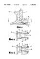
- FIG. 2illustrates a second embodiment of a tool for removing a retained spring clip
- FIG. 3illustrates the embodiment of FIG. 2 in use
- FIG. 4illustrates in cross section the position of the body of a tool of the present invention
- FIG. 5illustrates a section taken through the line 5' to 5' from FIG. 4;
- FIG. 6illustrates a section of FIG. 5 as the tool is used.
- the tool 10useful for removing a retained spring clip 11.
- the tool 10comprises a body 12 and handle 14. Attached to the handle 14 is a means for delivering an impact to the body 12 comprising a sliding impact hammer 26.
- the body 12comprises a wedge having a flattened front face 13.
- the body 12is adapted to be fitted between rail track 18 and the outer edges of the clip 11 as shown in FIG. 4.
- the body 12has a bulbous portion 20 extending rearwardly therefrom the bulbous portion 20 is adapted to engage and bear against the inner surface of the rail track 18, so as to secure the tool 10 in position.
- the front face 13 of the body 12has a recess 22 located at a lower end thereof.
- the recess 22is adapted to fit around the outer longitudinal edges of the clip 11, and edges of the recess 22 are inclined towards each other so as to form a triangular recess.
- a recess(not shown) is also cut into rear face of the body 12. This effect of this latter recess is to reduce the overall weight of the body 12 and therefore the tool 10.
- the handle 14is aligned with a longitudinal axis of the body 12 and extends generally upwardly therefrom.
- the handle 14is formed of a tubular inner section 24.
- a generally tubular outer section 26is slidingly inserted over the inner section 24.
- the outer section 26is able to move freely over the inner section 24.
- the outer section 26functions as an impact hammer 26.
- FIGS. 2 and 3A second embodiment of the present invention is shown in FIGS. 2 and 3.
- FIGS. 2 and 3Shown in FIGS. 2 and 3 is a tool 28 for removing a retained spring clip 11.
- the embodiment shown in FIGS. 2 and 3includes many of the features described for the tool 10 and like numerals will be used to describe like parts.
- the tool 28includes a body 12 and a handle 14. Additionally, the tool 28 incorporates a protective shroud 30.
- the shroud 30is located at the junction of the body 12 and handle 14 and comprises an arcuate cover formed of elastomeric materials with bound metal edges 32.
- the shroud 30extends forwardly of the body 12 so as to entirely cover the spring clip 11.
- FIG. 4Shown in FIG. 4 in cross section is a spring clip and railway track assembly.
- the clip 11is shown in position retaining a rail 34 in position.
- outer toes 36 of the clip 11rest so as to be outside of a gate 37 in the rail shoulder 38.
- the tool 10, 28is fitted into position between the uprights of the rail 34 and the clip 11 such that the recess 22 is fitted around the toes 36. This is shown in cross section in FIG. 5.
- the outer tube 26 of the handle 14is used in a manner of an impact hammer to create a downward force of the body 12 thereby forcing the toes 36 of the clip 11 through the recess 22.
- the toes 36are compressed as shown cross sectionally in FIG. 6.
- the tool 10may then be used to push the clip 11 through the gate 37.
- the bulbous portion 20is useful in that, by bearing against the rail track the clip may be urged forwardly through the gate 37.
- a particular type of clipis shown.
- other types of clipare also available, these other types including substantially more solid clips.
- the toes of a substantially more solid cliprequire a considerably greater force to produce the compression necessary to release the clip.
- the means capable of delivering an impact to the bodywould be modified so as to be able to produce a sufficient impact. Using a hydraulic impact means this would, of course be readily achievable.
- shroud 30is useful for restricting any undesirably excessive movement of the clip 11.
- the tool 10, 30is readily operated with an operator standing behind the clip 11 thereby being protected from any unwanted impact with a clip 11. It can also be seen that the tool 10, 30 is easily operated by a single person.
Landscapes
- Engineering & Computer Science (AREA)
- Mechanical Engineering (AREA)
- Architecture (AREA)
- Civil Engineering (AREA)
- Structural Engineering (AREA)
- Percussive Tools And Related Accessories (AREA)
Abstract
Description
Claims (11)
Priority Applications (1)
| Application Number | Priority Date | Filing Date | Title |
|---|---|---|---|
| US08/205,998US5392504A (en) | 1994-03-04 | 1994-03-04 | Spring clip remover and removal method |
Applications Claiming Priority (1)
| Application Number | Priority Date | Filing Date | Title |
|---|---|---|---|
| US08/205,998US5392504A (en) | 1994-03-04 | 1994-03-04 | Spring clip remover and removal method |
Publications (1)
| Publication Number | Publication Date |
|---|---|
| US5392504Atrue US5392504A (en) | 1995-02-28 |
Family
ID=22764560
Family Applications (1)
| Application Number | Title | Priority Date | Filing Date |
|---|---|---|---|
| US08/205,998Expired - LifetimeUS5392504A (en) | 1994-03-04 | 1994-03-04 | Spring clip remover and removal method |
Country Status (1)
| Country | Link |
|---|---|
| US (1) | US5392504A (en) |
Cited By (12)
| Publication number | Priority date | Publication date | Assignee | Title |
|---|---|---|---|---|
| WO1997004175A1 (en)* | 1995-07-18 | 1997-02-06 | Everts & Van Der Weijden Exploitatie Maatschappij Ewem B.V. | A tool for removing a railway fastening clip from a rail |
| US5628102A (en)* | 1996-02-28 | 1997-05-13 | Johnson; Wade T. | Device for removing railroad rail retainer clips |
| WO1999024669A1 (en)* | 1997-11-06 | 1999-05-20 | A. Rosenquist Förvaltnings Ab | An arrangement for bringing a clamping element from a fastening position to a released position |
| DE19812717A1 (en)* | 1998-03-24 | 1999-09-30 | Itt Mfg Enterprises Inc | Fitting tool for spring arrangement of motor vehicle disc brakes |
| US6108882A (en)* | 1997-12-22 | 2000-08-29 | Hodgson; Dave | Brake spring tool |
| US6202273B1 (en)* | 1999-07-30 | 2001-03-20 | General Electric Company | Shim removing tool |
| US6665920B2 (en)* | 2000-07-07 | 2003-12-23 | Giat Industries | Track-laying assistance device |
| US7028594B1 (en)* | 2002-03-23 | 2006-04-18 | Robert Mentken | Split ring and pellet method stitchless fastener coil separation tool |
| US20100012521A1 (en)* | 1998-10-08 | 2010-01-21 | Feldman Benjamin J | Small Volume In Vitro Sensor and Methods of Making |
| US8375544B1 (en)* | 2008-10-17 | 2013-02-19 | Portaco, Inc. | Railroad pin removal system |
| WO2016133736A1 (en)* | 2015-02-16 | 2016-08-25 | Progress Rail Services Corporation | Rail clip tool |
| CN113215876A (en)* | 2021-05-24 | 2021-08-06 | 中铁十一局集团第三工程有限公司 | Long rail laying stress relieving and locking method |
Citations (4)
| Publication number | Priority date | Publication date | Assignee | Title |
|---|---|---|---|---|
| US1873294A (en)* | 1931-05-04 | 1932-08-23 | John T Cosgrove | Puller |
| SU919858A1 (en)* | 1980-06-11 | 1982-04-15 | Северо-Кавказская Ордена Ленина Железная Дорога, Краснодарский Участок Энергоснабжения | Hand tool for disassembling parts mainly insulator locking springs |
| US4454792A (en)* | 1982-12-16 | 1984-06-19 | Burris Wesley E | Extending bar stake puller |
| US5140741A (en)* | 1990-04-23 | 1992-08-25 | Bible Kenneth G | Method of removing an automotive head liner |
- 1994
- 1994-03-04USUS08/205,998patent/US5392504A/ennot_activeExpired - Lifetime
Patent Citations (4)
| Publication number | Priority date | Publication date | Assignee | Title |
|---|---|---|---|---|
| US1873294A (en)* | 1931-05-04 | 1932-08-23 | John T Cosgrove | Puller |
| SU919858A1 (en)* | 1980-06-11 | 1982-04-15 | Северо-Кавказская Ордена Ленина Железная Дорога, Краснодарский Участок Энергоснабжения | Hand tool for disassembling parts mainly insulator locking springs |
| US4454792A (en)* | 1982-12-16 | 1984-06-19 | Burris Wesley E | Extending bar stake puller |
| US5140741A (en)* | 1990-04-23 | 1992-08-25 | Bible Kenneth G | Method of removing an automotive head liner |
Cited By (15)
| Publication number | Priority date | Publication date | Assignee | Title |
|---|---|---|---|---|
| US5884381A (en)* | 1995-07-18 | 1999-03-23 | Everts & Van Der Weijden Exploitatie Maatschappij Ewem B. V. | Tool for removing a railway fastening clip from a rail |
| WO1997004175A1 (en)* | 1995-07-18 | 1997-02-06 | Everts & Van Der Weijden Exploitatie Maatschappij Ewem B.V. | A tool for removing a railway fastening clip from a rail |
| US5628102A (en)* | 1996-02-28 | 1997-05-13 | Johnson; Wade T. | Device for removing railroad rail retainer clips |
| WO1999024669A1 (en)* | 1997-11-06 | 1999-05-20 | A. Rosenquist Förvaltnings Ab | An arrangement for bringing a clamping element from a fastening position to a released position |
| US6108882A (en)* | 1997-12-22 | 2000-08-29 | Hodgson; Dave | Brake spring tool |
| DE19812717A1 (en)* | 1998-03-24 | 1999-09-30 | Itt Mfg Enterprises Inc | Fitting tool for spring arrangement of motor vehicle disc brakes |
| US20100012521A1 (en)* | 1998-10-08 | 2010-01-21 | Feldman Benjamin J | Small Volume In Vitro Sensor and Methods of Making |
| US6202273B1 (en)* | 1999-07-30 | 2001-03-20 | General Electric Company | Shim removing tool |
| US6412161B2 (en)* | 1999-07-30 | 2002-07-02 | General Electric Company | Shim removing method |
| US6665920B2 (en)* | 2000-07-07 | 2003-12-23 | Giat Industries | Track-laying assistance device |
| US7028594B1 (en)* | 2002-03-23 | 2006-04-18 | Robert Mentken | Split ring and pellet method stitchless fastener coil separation tool |
| US8375544B1 (en)* | 2008-10-17 | 2013-02-19 | Portaco, Inc. | Railroad pin removal system |
| WO2016133736A1 (en)* | 2015-02-16 | 2016-08-25 | Progress Rail Services Corporation | Rail clip tool |
| AU2016220376B2 (en)* | 2015-02-16 | 2019-02-14 | Progress Rail Services Corporation | Rail clip tool |
| CN113215876A (en)* | 2021-05-24 | 2021-08-06 | 中铁十一局集团第三工程有限公司 | Long rail laying stress relieving and locking method |
Similar Documents
| Publication | Publication Date | Title |
|---|---|---|
| US5392504A (en) | Spring clip remover and removal method | |
| CA2229084C (en) | Drill for drilling crossties, particularly for use in the railroad sector | |
| DE2455268C3 (en) | Collision protection for the beginnings of a guardrail | |
| EP0115685B1 (en) | Guardrail end terminal | |
| CA2246120C (en) | Vehicle capture device | |
| US6622361B1 (en) | Railroad clip removal system having a pair of arms within a guide slot | |
| US6244571B1 (en) | Controlled buckling breakaway cable terminal | |
| WO2012083339A1 (en) | Apparatus for the application or removal of railway track fasteners | |
| CA2116923C (en) | Spring clip remover | |
| US4405005A (en) | Firewood splitter | |
| US20030081997A1 (en) | Vehicle crash wall | |
| US20050254915A1 (en) | Catcher tire abutment device for restraining road vehicle on a transport vehicle | |
| US3881422A (en) | Tie replacing system | |
| US4018165A (en) | Tie replacing system | |
| US5884381A (en) | Tool for removing a railway fastening clip from a rail | |
| CN214993061U (en) | Bridge buffer stop of easy to maintain | |
| WO1997049625A1 (en) | Restraining device for the wheels of a motor vehicle | |
| US4444345A (en) | Rail lifting and cutting machine | |
| WO1995005878A1 (en) | A post and rail assembly | |
| US4316508A (en) | Automatic ripper reset mechanism | |
| CN210315277U (en) | Anti-reverse-running non-Newtonian fluid deceleration strip | |
| CA1299987C (en) | Vehicle safety device | |
| KR20130093315A (en) | Balise holding device for automatic train protection | |
| US4383630A (en) | Rail lifting and cutting machine | |
| DE10144212C1 (en) | Under-run guard for utility vehicle comprises bumper attached to force-absorbing component with inverted V-shaped groove which crumples when bumper hits obstacle with force exceeding threshold value |
Legal Events
| Date | Code | Title | Description |
|---|---|---|---|
| AS | Assignment | Owner name:EVERTS & VAN DER WEIJDEN EXPLOITATIE MAATSCHAPPI Free format text:ASSIGNMENT OF ASSIGNORS INTEREST;ASSIGNOR:CALUSINSKI, RICHARD R.;REEL/FRAME:006906/0857 Effective date:19940301 | |
| STCF | Information on status: patent grant | Free format text:PATENTED CASE | |
| FEPP | Fee payment procedure | Free format text:PAYER NUMBER DE-ASSIGNED (ORIGINAL EVENT CODE: RMPN); ENTITY STATUS OF PATENT OWNER: LARGE ENTITY Free format text:PAYOR NUMBER ASSIGNED (ORIGINAL EVENT CODE: ASPN); ENTITY STATUS OF PATENT OWNER: LARGE ENTITY | |
| FEPP | Fee payment procedure | Free format text:PAYOR NUMBER ASSIGNED (ORIGINAL EVENT CODE: ASPN); ENTITY STATUS OF PATENT OWNER: LARGE ENTITY | |
| FEPP | Fee payment procedure | Free format text:PAYER NUMBER DE-ASSIGNED (ORIGINAL EVENT CODE: RMPN); ENTITY STATUS OF PATENT OWNER: LARGE ENTITY Free format text:PAYOR NUMBER ASSIGNED (ORIGINAL EVENT CODE: ASPN); ENTITY STATUS OF PATENT OWNER: LARGE ENTITY Free format text:PAT HLDR NO LONGER CLAIMS SMALL ENT STAT AS SMALL BUSINESS (ORIGINAL EVENT CODE: LSM2); ENTITY STATUS OF PATENT OWNER: LARGE ENTITY | |
| FEPP | Fee payment procedure | Free format text:PAYER NUMBER DE-ASSIGNED (ORIGINAL EVENT CODE: RMPN); ENTITY STATUS OF PATENT OWNER: LARGE ENTITY Free format text:PAYOR NUMBER ASSIGNED (ORIGINAL EVENT CODE: ASPN); ENTITY STATUS OF PATENT OWNER: LARGE ENTITY | |
| FPAY | Fee payment | Year of fee payment:4 | |
| FPAY | Fee payment | Year of fee payment:8 | |
| FPAY | Fee payment | Year of fee payment:12 | |
| FEPP | Fee payment procedure | Free format text:PAYER NUMBER DE-ASSIGNED (ORIGINAL EVENT CODE: RMPN); ENTITY STATUS OF PATENT OWNER: LARGE ENTITY Free format text:PAYOR NUMBER ASSIGNED (ORIGINAL EVENT CODE: ASPN); ENTITY STATUS OF PATENT OWNER: LARGE ENTITY |