US5391027A - Machine tool system - Google Patents
Machine tool systemDownload PDFInfo
- Publication number
- US5391027A US5391027AUS08/218,407US21840794AUS5391027AUS 5391027 AUS5391027 AUS 5391027AUS 21840794 AUS21840794 AUS 21840794AUS 5391027 AUS5391027 AUS 5391027A
- Authority
- US
- United States
- Prior art keywords
- clamping unit
- annular
- guide member
- sleeve
- tool holder
- Prior art date
- Legal status (The legal status is an assumption and is not a legal conclusion. Google has not performed a legal analysis and makes no representation as to the accuracy of the status listed.)
- Expired - Fee Related
Links
Images
Classifications
- B—PERFORMING OPERATIONS; TRANSPORTING
- B23—MACHINE TOOLS; METAL-WORKING NOT OTHERWISE PROVIDED FOR
- B23B—TURNING; BORING
- B23B29/00—Holders for non-rotary cutting tools; Boring bars or boring heads; Accessories for tool holders
- B23B29/04—Tool holders for a single cutting tool
- B23B29/046—Tool holders for a single cutting tool with an intermediary toolholder
- B—PERFORMING OPERATIONS; TRANSPORTING
- B23—MACHINE TOOLS; METAL-WORKING NOT OTHERWISE PROVIDED FOR
- B23B—TURNING; BORING
- B23B31/00—Chucks; Expansion mandrels; Adaptations thereof for remote control
- B23B31/02—Chucks
- B23B31/24—Chucks characterised by features relating primarily to remote control of the gripping means
- B23B31/26—Chucks characterised by features relating primarily to remote control of the gripping means using mechanical transmission through the working-spindle
- B23B31/261—Chucks characterised by features relating primarily to remote control of the gripping means using mechanical transmission through the working-spindle clamping the end of the toolholder shank
- Y—GENERAL TAGGING OF NEW TECHNOLOGICAL DEVELOPMENTS; GENERAL TAGGING OF CROSS-SECTIONAL TECHNOLOGIES SPANNING OVER SEVERAL SECTIONS OF THE IPC; TECHNICAL SUBJECTS COVERED BY FORMER USPC CROSS-REFERENCE ART COLLECTIONS [XRACs] AND DIGESTS
- Y10—TECHNICAL SUBJECTS COVERED BY FORMER USPC
- Y10T—TECHNICAL SUBJECTS COVERED BY FORMER US CLASSIFICATION
- Y10T279/00—Chucks or sockets
- Y10T279/10—Expanding
- Y10T279/1037—Axially moving actuator
- Y10T279/1041—Wedge
- Y—GENERAL TAGGING OF NEW TECHNOLOGICAL DEVELOPMENTS; GENERAL TAGGING OF CROSS-SECTIONAL TECHNOLOGIES SPANNING OVER SEVERAL SECTIONS OF THE IPC; TECHNICAL SUBJECTS COVERED BY FORMER USPC CROSS-REFERENCE ART COLLECTIONS [XRACs] AND DIGESTS
- Y10—TECHNICAL SUBJECTS COVERED BY FORMER USPC
- Y10T—TECHNICAL SUBJECTS COVERED BY FORMER US CLASSIFICATION
- Y10T409/00—Gear cutting, milling, or planing
- Y10T409/30—Milling
- Y10T409/309352—Cutter spindle or spindle support
- Y10T409/309408—Cutter spindle or spindle support with cutter holder
- Y10T409/309464—Cutter spindle or spindle support with cutter holder and draw bar
- Y—GENERAL TAGGING OF NEW TECHNOLOGICAL DEVELOPMENTS; GENERAL TAGGING OF CROSS-SECTIONAL TECHNOLOGIES SPANNING OVER SEVERAL SECTIONS OF THE IPC; TECHNICAL SUBJECTS COVERED BY FORMER USPC CROSS-REFERENCE ART COLLECTIONS [XRACs] AND DIGESTS
- Y10—TECHNICAL SUBJECTS COVERED BY FORMER USPC
- Y10T—TECHNICAL SUBJECTS COVERED BY FORMER US CLASSIFICATION
- Y10T82/00—Turning
- Y10T82/25—Lathe
- Y10T82/2585—Tool rest
- Y10T82/2589—Quick release tool or holder clamp
Definitions
- This inventionrelates to a machine tool system, and more particularly to a mechanism for securely clamping a cutting tool holder in a cutting machine.
- U.S. Pat. No. 5,193,954issued to Carl Hunt on Mar. 16, 1993, discloses a machine tool system that comprises a clamping device mounted in the head of a cutting machine.
- the machine headcan be rotating or non-rotating.
- the clamping devicehas a socket adapted to receive therein a cutting tool holder, whereby various different cutting tools can be selectively mounted on the cutting machine head.
- the cutting tool holdercomprises a tubular section having a frusto-conical outer surface adapted to seat against a conical socket surface.
- the inner surface of the tubular sectionforms an annular lip that is engageable with individual wedge lock elements that are radially movable to exert axial lock forces on the tubular section of the cutting tool holder.
- An axially movable drawbaris provided to move the wedge lock elements into or out of engagement with the annular lip on the tool holder.
- the tool holderhas a wedge lock fit in the frusto-conical socket of the clamping device, whereby the tool holder has a secure non-wobbling securement in the clamping device.
- a clutch meansbetween the clamping device and tool holder in order to prevent circumferential slippage between the tool holder and clamping device.
- the clutch meanscomprises an annular toothed member bolted onto an internal end surface of the clamping device.
- the tubular section of the tool holderhas multiple grooves in its end surface that fit onto the teeth of the annular toothed member, to establish a non-slip drive connection between the clamping unit and tool holder.
- the present inventionrelates to a machine tool system of the type disclosed in U.S. Pat. No. 5,193,954, wherein an improved low cost clutch means is provided between the clamping unit and the tool holder.
- the clamping unitcomprises an annular guide member having radial guide slots for the individual wedge lock elements, and a sleeve having a telescopic fit on the annular guide member.
- the sleevehas a single axial key slot that serves to mount a drive key.
- the tool holdercomprises a tubular section that has an axial groove in its end surface adapted to fit onto the drive key in the clamping unit.
- the drive keyconstitutes a relatively low cost clutch for preventing circumferential slippage between the clamping unit and tool holder.
- the principal aim of the inventionis to provide a machine tool system having a relatively low cost driving connection between a clamping unit and an associated cutting tool holder.
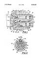
- FIG. 1is a longitudinal sectional view taken through a machine tool system constructed according to the invention.
- FIG. 2is a sectional view taken on line 2--2 in.
- FIG. 1
- the headcan be a driven rotary head or a non-rotating head, depending on the machine structure and the nature of the work to be machined.
- Head 12has a cylindrical bore 14 adapted to receive therein a clamping unit 16 for a cutting tool holder 17.
- the cutting implement (or tool)is designated by numeral 19.
- the tool holder 17is removably gripped or clamped by clamping unit 16, whereby a given tool holder can be replaced with another tool holder having a different cutting tool or a newly sharpened cutting tool.
- the cutting machinecan include a numerically controlled tool changer device for transferring tool holder 17 between a stored (inactive) position in a storage mechanism and an operating position inserted into clamping unit 16.
- Clamping unit 16comprises an annular guide member 21 having an external cylindrical side surface 22 and a central longitudinal axis 23. Near its leading (left) end, annular guide member 21 has six radially oriented guide slots 24. A wedge lock element 25 is slidably mounted in each guide slot.
- Clamping unit 16further comprises a sleeve 27 that has a telescopic press fit on annular guide member 21.
- the guide memberhas an annular recess in its side surface 22 that forms an inset surface 29.
- Sleeve 27is press fit on inset surface 29 so that the external surface 31 of the sleeve is an axial continuation of surface 22.
- Guide member 21 and sleeve 27are rigidly joined together by their press fit connection.
- a set screw 37is extended through the sleeve into inset surface 29, as an additional connection means.
- a radial mounting flange 39extends from sleeve 27 for detachably mounting the clamping unit on the cutting machine head; a series of bolts 40 attaches the mounting flange to machine head 12.
- a single axial key slot 41is provided in the right end of sleeve 27 for mounting a flat-sided drive key 43.
- the drive keyhas an outer edge 44 aligned with the external surface of sleeve 27, and an inner edge 45 abutting guide member 21.
- Sleeve 27has an internal frusto-conical socket surface 33 adapted to mate with a frusto-conical surface 35 on tool holder 17.
- the slope angles of the two frusto-conical surfaces 33 and 35are the same, such that these surfaces are in contact along the entire length of surface engagement when the tool holder is inserted into the clamping unit.
- Tool holder 17is internally recessed so that the holder has a tubular section insertable into the clamping unit.
- a single axial groove 47is provided in the tubular section of the tool holder for fitting onto the drive key 43, whereby a driving connection is established between the clamping unit 16 and the tool holder 17.
- the inner surface of the tool holder tubular sectionforms an annular lip that has a conical surface 49 engageable with the wedge lock elements 25, whereby the tool holder is firmly wedged against the frusto-conical surface 33 on sleeve 27.
- the wedge lock elements 25are driven outwardly into engagement with lip surface 49 by means of a drawbar 51 and rotary actuator 53.
- the drawbar, actuator, and wedge lock elementscan be constructed as shown in aforementioned U.S. Pat. No. 5,193,954.
- Rotary movement of the actuator in one directionadvances the drawbar 51 rightwardly; such that the flat cam surfaces 55 on the drawbar move wedge lock elements 25 outwardly in guide slots 24, thereby wedging the tubular section of tool holder 17 tightly against conical surface 33 of the clamping unit.
- Reverse rotational motion of actuator 53moves drawbar 51 leftwardly, so as to enable the tool holder to be unclamped from the clamping unit.
- the wedge lock elementsmay be equipped with a resilient returning means, as shown in FIG. 4 of U.S. Pat. No. 5,193,954.
- the herein illustrated machine tool systemis generally similar to the systems shown in U.S. Pat. No. 5,193,954.
- a feature of the present inventionis the use of a single drive key 43 positioned in key slot 41 of sleeve 27 for establishing a driving connection between the clamping unit and tool holder 17.
- Drive key 43constitutes a manufacturing cost improvement over the annular multi-toothed drive member used in the system illustrated in U.S. Pat. No. 5,193,954.
Landscapes
- Engineering & Computer Science (AREA)
- Mechanical Engineering (AREA)
- Cutting Tools, Boring Holders, And Turrets (AREA)
- Gripping On Spindles (AREA)
Abstract
Description
Claims (5)
Priority Applications (5)
| Application Number | Priority Date | Filing Date | Title |
|---|---|---|---|
| US08/218,407US5391027A (en) | 1994-03-28 | 1994-03-28 | Machine tool system |
| AU14915/95AAU1491595A (en) | 1994-03-28 | 1995-03-17 | Machine tool system |
| CA002145430ACA2145430A1 (en) | 1994-03-28 | 1995-03-24 | Machine tool system |
| JP7090093AJPH0839314A (en) | 1994-03-28 | 1995-03-24 | Machine tool system |
| DE19511260ADE19511260A1 (en) | 1994-03-28 | 1995-03-27 | Machine tool system |
Applications Claiming Priority (1)
| Application Number | Priority Date | Filing Date | Title |
|---|---|---|---|
| US08/218,407US5391027A (en) | 1994-03-28 | 1994-03-28 | Machine tool system |
Publications (1)
| Publication Number | Publication Date |
|---|---|
| US5391027Atrue US5391027A (en) | 1995-02-21 |
Family
ID=22814993
Family Applications (1)
| Application Number | Title | Priority Date | Filing Date |
|---|---|---|---|
| US08/218,407Expired - Fee RelatedUS5391027A (en) | 1994-03-28 | 1994-03-28 | Machine tool system |
Country Status (5)
| Country | Link |
|---|---|
| US (1) | US5391027A (en) |
| JP (1) | JPH0839314A (en) |
| AU (1) | AU1491595A (en) |
| CA (1) | CA2145430A1 (en) |
| DE (1) | DE19511260A1 (en) |
Cited By (7)
| Publication number | Priority date | Publication date | Assignee | Title |
|---|---|---|---|---|
| US5827021A (en)* | 1996-01-03 | 1998-10-27 | Klement; Klaus-Dieter | Releasable tool-holder mount for machining spindle |
| US5911547A (en)* | 1995-12-23 | 1999-06-15 | Klement; Klaus-Dieter | Mount for tool holder on spindle shaft |
| US20060188353A1 (en)* | 2005-02-22 | 2006-08-24 | O-M Ltd. | Tool mounting device for turning center |
| US20070079489A1 (en)* | 2005-10-07 | 2007-04-12 | Master Tool Corporation | Rotational tool alignment adapter arrangement and associated provision method |
| US20080252023A1 (en)* | 2005-09-13 | 2008-10-16 | Eugen Hangleiter | Apparatus for Chucking a Tool or Workpiece Having a Collet |
| US20090047077A1 (en)* | 2007-08-13 | 2009-02-19 | Billy Fielder | Tool Holder and Method for Machining Apparatus |
| CN111545814A (en)* | 2020-06-23 | 2020-08-18 | 广州优讯环保科技有限公司 | Processing milling machine |
Families Citing this family (1)
| Publication number | Priority date | Publication date | Assignee | Title |
|---|---|---|---|---|
| CN107127364B (en)* | 2017-06-02 | 2020-05-12 | 嘉兴晟源工业设计有限公司 | Clamping device of pipe |
Citations (5)
| Publication number | Priority date | Publication date | Assignee | Title |
|---|---|---|---|---|
| US4406195A (en)* | 1980-02-28 | 1983-09-27 | Fried. Krupp Gesellschaft Mit Beschrankter Haftung | Quick-release tool assembly |
| US4726269A (en)* | 1987-01-27 | 1988-02-23 | Kennametal Inc. | Toolholder assembly |
| US4736659A (en)* | 1987-01-27 | 1988-04-12 | Kennametal Inc. | Apparatus for holding a toolholder shank |
| US4784542A (en)* | 1985-03-01 | 1988-11-15 | Fried. Krupp Gesellschaft Mit Beschrankter Haftung | Tool-mounting assembly having an exchangeable tool head |
| US5193954A (en)* | 1991-10-30 | 1993-03-16 | Gte Valenite Corporation | Universal tool connection |
Family Cites Families (2)
| Publication number | Priority date | Publication date | Assignee | Title |
|---|---|---|---|---|
| DE3536183A1 (en)* | 1985-03-01 | 1986-09-04 | Fried. Krupp Gmbh, 4300 Essen | Tool arrangement with interchangeable tool head |
| DE3532891A1 (en)* | 1985-09-14 | 1987-03-26 | Krupp Gmbh | TOOL CLUTCH |
- 1994
- 1994-03-28USUS08/218,407patent/US5391027A/ennot_activeExpired - Fee Related
- 1995
- 1995-03-17AUAU14915/95Apatent/AU1491595A/ennot_activeAbandoned
- 1995-03-24CACA002145430Apatent/CA2145430A1/ennot_activeAbandoned
- 1995-03-24JPJP7090093Apatent/JPH0839314A/ennot_activeWithdrawn
- 1995-03-27DEDE19511260Apatent/DE19511260A1/ennot_activeCeased
Patent Citations (5)
| Publication number | Priority date | Publication date | Assignee | Title |
|---|---|---|---|---|
| US4406195A (en)* | 1980-02-28 | 1983-09-27 | Fried. Krupp Gesellschaft Mit Beschrankter Haftung | Quick-release tool assembly |
| US4784542A (en)* | 1985-03-01 | 1988-11-15 | Fried. Krupp Gesellschaft Mit Beschrankter Haftung | Tool-mounting assembly having an exchangeable tool head |
| US4726269A (en)* | 1987-01-27 | 1988-02-23 | Kennametal Inc. | Toolholder assembly |
| US4736659A (en)* | 1987-01-27 | 1988-04-12 | Kennametal Inc. | Apparatus for holding a toolholder shank |
| US5193954A (en)* | 1991-10-30 | 1993-03-16 | Gte Valenite Corporation | Universal tool connection |
Cited By (9)
| Publication number | Priority date | Publication date | Assignee | Title |
|---|---|---|---|---|
| US5911547A (en)* | 1995-12-23 | 1999-06-15 | Klement; Klaus-Dieter | Mount for tool holder on spindle shaft |
| US5827021A (en)* | 1996-01-03 | 1998-10-27 | Klement; Klaus-Dieter | Releasable tool-holder mount for machining spindle |
| US20060188353A1 (en)* | 2005-02-22 | 2006-08-24 | O-M Ltd. | Tool mounting device for turning center |
| US7220089B2 (en)* | 2005-02-22 | 2007-05-22 | O-M Ltd. | Tool mounting device for turning center |
| US20080252023A1 (en)* | 2005-09-13 | 2008-10-16 | Eugen Hangleiter | Apparatus for Chucking a Tool or Workpiece Having a Collet |
| US8246280B2 (en)* | 2005-09-13 | 2012-08-21 | Roehm Gmbh | Apparatus for chucking a tool or workpiece having a collet |
| US20070079489A1 (en)* | 2005-10-07 | 2007-04-12 | Master Tool Corporation | Rotational tool alignment adapter arrangement and associated provision method |
| US20090047077A1 (en)* | 2007-08-13 | 2009-02-19 | Billy Fielder | Tool Holder and Method for Machining Apparatus |
| CN111545814A (en)* | 2020-06-23 | 2020-08-18 | 广州优讯环保科技有限公司 | Processing milling machine |
Also Published As
| Publication number | Publication date |
|---|---|
| AU1491595A (en) | 1995-10-05 |
| JPH0839314A (en) | 1996-02-13 |
| CA2145430A1 (en) | 1995-09-29 |
| DE19511260A1 (en) | 1995-10-05 |
Similar Documents
| Publication | Publication Date | Title |
|---|---|---|
| AU724736B2 (en) | Tool-less machine tool chuck | |
| AU765865B2 (en) | Toolholder assembly | |
| US6966562B1 (en) | Multiple mode chuck | |
| US6270086B1 (en) | Collet actuator for tool holder | |
| EP0059513B1 (en) | Mounting device for cutting tools | |
| WO1997048513A9 (en) | Tool-less machine tool chuck | |
| GB2360722A (en) | Handheld machine tool with detachable tool holding device | |
| JPH0435297B2 (en) | ||
| JPH0839310A (en) | Boring tool with freely adjustable cutter element | |
| HU194079B (en) | Drill chuck for manual devices | |
| US5391027A (en) | Machine tool system | |
| EP0668807B1 (en) | Shank for a milling tool including recesses for cooperation with a chuck | |
| US6575477B2 (en) | Quick change true length collet chuck assembly | |
| US4777714A (en) | Quick-change mount for chucks | |
| EP0488361B1 (en) | Tool holding device | |
| US5265990A (en) | Short toolholder system | |
| US4729700A (en) | Drive unit for rotary tools | |
| US6971825B2 (en) | Milling tool holder with differential screw | |
| EP0684884B1 (en) | Fastening device for milling tools and the like, adaptable for various holder sizes | |
| EP1753569B1 (en) | Toolholder assembly | |
| US6279437B1 (en) | Pipe beveling machine | |
| US6533292B2 (en) | Pull-to-close collet chuck | |
| HK1007291A1 (en) | Tool chuck for equipment of a rotating machine like a drilling machine | |
| CN112703081B (en) | Electric drive system for machine tool and method for operating the same | |
| US5829762A (en) | Chuck with locking unit |
Legal Events
| Date | Code | Title | Description |
|---|---|---|---|
| AS | Assignment | Owner name:VALENTE INC., MICHIGAN Free format text:ASSIGNMENT OF ASSIGNORS INTEREST;ASSIGNOR:GREEN, RICHARD SCOTT;REEL/FRAME:006940/0822 Effective date:19940321 | |
| FPAY | Fee payment | Year of fee payment:4 | |
| FEPP | Fee payment procedure | Free format text:PAYOR NUMBER ASSIGNED (ORIGINAL EVENT CODE: ASPN); ENTITY STATUS OF PATENT OWNER: LARGE ENTITY | |
| AS | Assignment | Owner name:BANKERS TRUST COMPANY, AS ADMINISTRATIVE AGENT, NE Free format text:SECURITY AGREEMENT;ASSIGNORS:VALENITE U.S.A. INC.;MILACRON INC.;TALBOT HOLDINGS, LTD.;AND OTHERS;REEL/FRAME:013110/0122 Effective date:20011210 | |
| FPAY | Fee payment | Year of fee payment:8 | |
| AS | Assignment | Owner name:VALENITE INC., MICHIGAN Free format text:RELEASE OF INTELLECTUAL PROPERTY;ASSIGNOR:DEUTSCHE BANK TRUST COMPANY AMERICAS (F/K/A BANKERS TRUST COMPANY), AS ADMINISTRATIVE AGENT;REEL/FRAME:013169/0258 Effective date:20020809 | |
| REMI | Maintenance fee reminder mailed | ||
| AS | Assignment | Owner name:VALENITE, LLC, DELAWARE Free format text:CHANGE OF NAME;ASSIGNOR:VALENITE INC.;REEL/FRAME:015065/0500 Effective date:20031231 | |
| REMI | Maintenance fee reminder mailed | ||
| LAPS | Lapse for failure to pay maintenance fees | ||
| STCH | Information on status: patent discontinuation | Free format text:PATENT EXPIRED DUE TO NONPAYMENT OF MAINTENANCE FEES UNDER 37 CFR 1.362 | |
| FP | Lapsed due to failure to pay maintenance fee | Effective date:20070221 |