US5390631A - Use of single-lead and multi-lead ribbed tubing for sliding pressure once-through boilers - Google Patents
Use of single-lead and multi-lead ribbed tubing for sliding pressure once-through boilersDownload PDFInfo
- Publication number
- US5390631A US5390631AUS08/249,183US24918394AUS5390631AUS 5390631 AUS5390631 AUS 5390631AUS 24918394 AUS24918394 AUS 24918394AUS 5390631 AUS5390631 AUS 5390631A
- Authority
- US
- United States
- Prior art keywords
- furnace
- fluid
- tubes
- cooled
- once
- Prior art date
- Legal status (The legal status is an assumption and is not a legal conclusion. Google has not performed a legal analysis and makes no representation as to the accuracy of the status listed.)
- Expired - Lifetime
Links
Images


Classifications
- F—MECHANICAL ENGINEERING; LIGHTING; HEATING; WEAPONS; BLASTING
- F22—STEAM GENERATION
- F22B—METHODS OF STEAM GENERATION; STEAM BOILERS
- F22B29/00—Steam boilers of forced-flow type
- F22B29/06—Steam boilers of forced-flow type of once-through type, i.e. built-up from tubes receiving water at one end and delivering superheated steam at the other end of the tubes
- F22B29/061—Construction of tube walls
- F22B29/062—Construction of tube walls involving vertically-disposed water tubes
- F—MECHANICAL ENGINEERING; LIGHTING; HEATING; WEAPONS; BLASTING
- F28—HEAT EXCHANGE IN GENERAL
- F28D—HEAT-EXCHANGE APPARATUS, NOT PROVIDED FOR IN ANOTHER SUBCLASS, IN WHICH THE HEAT-EXCHANGE MEDIA DO NOT COME INTO DIRECT CONTACT
- F28D7/00—Heat-exchange apparatus having stationary tubular conduit assemblies for both heat-exchange media, the media being in contact with different sides of a conduit wall
- F—MECHANICAL ENGINEERING; LIGHTING; HEATING; WEAPONS; BLASTING
- F28—HEAT EXCHANGE IN GENERAL
- F28F—DETAILS OF HEAT-EXCHANGE AND HEAT-TRANSFER APPARATUS, OF GENERAL APPLICATION
- F28F13/00—Arrangements for modifying heat-transfer, e.g. increasing, decreasing
- Y—GENERAL TAGGING OF NEW TECHNOLOGICAL DEVELOPMENTS; GENERAL TAGGING OF CROSS-SECTIONAL TECHNOLOGIES SPANNING OVER SEVERAL SECTIONS OF THE IPC; TECHNICAL SUBJECTS COVERED BY FORMER USPC CROSS-REFERENCE ART COLLECTIONS [XRACs] AND DIGESTS
- Y02—TECHNOLOGIES OR APPLICATIONS FOR MITIGATION OR ADAPTATION AGAINST CLIMATE CHANGE
- Y02P—CLIMATE CHANGE MITIGATION TECHNOLOGIES IN THE PRODUCTION OR PROCESSING OF GOODS
- Y02P80/00—Climate change mitigation technologies for sector-wide applications
- Y02P80/10—Efficient use of energy, e.g. using compressed air or pressurized fluid as energy carrier
- Y02P80/15—On-site combined power, heat or cool generation or distribution, e.g. combined heat and power [CHP] supply
Definitions
- the present inventiongenerally relates to boilers or steam generators for electric power generation and, in particular, to a new and useful design of a sliding pressure once-through boiler using both single-lead and multi-lead ribbed tubing.
- a boiler feed pump 8 for the system 10provides the entire driving head to force the water through an economizer 11, an evaporator 12, and a superheater 14 which can be used in conjunction with a separator 13. Water is continuously evaporated to dryness and then superheated without any steam-water separation.
- This circulation methodis applicable to all operating pressures, i.e. supercritical (greater than 3208 psia) and subcritical (less than 3208 psia).
- the system 10uses spiral furnace circuitry for the evaporator 12 because a vertical tube design is more sensitive to upsets and nonuniform tube-to-tube heating. However, for start-up and low load operation, special by-pass systems are still needed.
- once-through boiler designs with superimposed recirculation systems 10a and 10bhave been used and are illustrated in FIGS. 2 and 3.
- These recirculation systemspermit partial recirculation of fluid to the furnace walls in order to increase the fluid velocity in the evaporator tubes by incorporating circulation pumps 15 and orifices 16.
- the design in many applicationsallows the furnace 12 to remain at constant pressure, typically supercritical pressure, and utilizes a separator or flash tank 13 for reducing the superheater pressure to subcritical pressures at start-up and low loads.
- These types of once-through boiler systems 10a and 10btypically utilize a vertical furnace tube evaporator design.
- Single-lead ribbed (SLR) tubeshave been employed by The Babcock & Wilcox Company (B&W), assignee of the present invention, in once-through, vertical tube, subcritical pressure boilers.
- Multi-lead ribbed (MLR), tubeshave been employed by B&W in some applications to once-through, vertical tube, supercritical pressure boilers, and to once-through, spiral-tube boilers operating at both sub- and supercritical pressures. Examples of these SLR and MLR tube geometries are shown in FIGS. 6-8 herein.
- U.S. Pat. Nos. 3,088,494 and 3,289,451 to Koch, et al.disclose, respectively, ribbed vapor generating tubes for sub-critical pressure vapor generators, and a method and apparatus for forming internal helical ribbing in a tube of the type disclosed in U.S. Pat. No. 3,088,494.
- the CHF in tubescauses excessive metal temperatures which must be avoided. This problem causes difficulty in designing a furnace evaporator for sliding pressure operation at low mass velocities. For sliding pressure operation, a certain load point will exist where the heat flux applied to the tube will be high enough that the heat transfer through the MLR tube wall into the fluid therein will not be sufficient and elevated tube temperatures will exist. The possibility of furnace tube failure could occur.
- the present inventionpertains to once-through, sliding pressure boilers or steam generators that have furnace wall tube orientations that can be vertical, horizontal or spiral (i.e., at an angle between the horizontal and vertical orientations), singly or in any combination thereof.
- One aspect of the present inventionis drawn to a once-through sliding pressure steam generator comprising an enclosure having an outlet and heat exchanger surfaces made of smooth bore tubes, single lead ribbed (SLR) tubes and multiple ribbed lead (MLR) tubes in a particular arrangement. All of these tubes are preferably constructed as membrane wall tube panels.
- the present inventionovercomes the above-identified problems by using SLR tubing in the furnace in those locations where the heat transfer will be impaired if MLR tubing is used.
- SLR tubesoperate on a different principle than swirl generation, and therefore do not depend upon the density difference of steam and water. Their CHF performance is adequate at near critical pressures in the range of lower mass velocities proposed in this invention.
- the steam generatorincludes burners for burning fuel and air within the enclosure which, in turn, create a low heat flux region, a medium heat flux region, and a high heat flux region of the steam generator.
- Water and/or steam(or, at supercritical pressures, the term "fluid" is used) flows through the tubes of the wall panels which provide an efficient heat exchanger.
- the smooth bore tubesare located at the low heat flux region of the steam generator, while the single lead ribbed (SLR) tubes and the multiple lead ribbed (MLR) tubes are selectively located at the medium and high heat flux regions of the steam generator.
- this inventioncan be used in steam generators employing various arrangements of vertical, horizontal or spiral tubes, it is a primary purpose of the present invention to provide a once-through, vertical tube, sliding pressure boiler or steam generator suitable for sliding pressure operation over a wide load range which provides the capability to operate at low minimum loads and with low pressure drop.
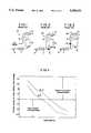
- FIG. 1is a schematic view illustrating one known once-through boiler system
- FIG. 2is a schematic view illustrating a second known once-through boiler system
- FIG. 3is a schematic view illustrating a third known once-through boiler system
- FIG. 4is a graph plotting changes in mass characteristics for vertical furnace tubing
- FIG. 5is a view in longitudinal cross-section of a tube having a smooth bore
- FIG. 6is a view in longitudinal cross-section of a single-lead ribbed (SLR) tube having a single continuous internal helical rib;
- SLRsingle-lead ribbed
- FIG. 7is a view in cross-section of a multiple-lead ribbed (MLR) tube having multiple continuous internal helical ribs;
- MLRmultiple-lead ribbed
- FIG. 8is a view in longitudinal cross-section of another MLR tube
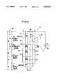
- FIG. 9is a schematic side view of a once-through, vertical tube steam generator suitable for sliding pressure operation according to a first embodiment of the present invention.
- FIG. 10is a schematic side view of a once-through, vertical tube steam generator suitable for sliding pressure operation according to a second embodiment of the present invention.
- FIG. 11is a schematic side view of a once-through, spiral tube steam generator suitable for sliding pressure operation according to a third embodiment of the present invention.
- FIG. 12is a schematic side view of a once-through, spiral tube steam generator suitable for sliding pressure operation according to a fourth embodiment of the present invention.
- FIG. 13is a schematic view in diametrical cross-section of a wall panel employing smooth tubes taken along line 14--14 of FIG. 9;
- FIG. 14is a schematic view diametrical cross-section of a wall panel employing SLR tubes taken along line 13--13 of FIG. 9;
- FIG. 15is a schematic view diametrical cross-section of a wall panel employing MLR tubes taken along line 15--15 of FIG. 9.
- FIG. 5shows a tube 20 having a smooth bore 22.
- FIG. 6shows a single-lead ribbed (SLR) tube 24 whose inner surface 26 has a single continuous, internal helical groove 28 located inbetween continuous helical lands or ribs 30.
- FIG. 7show a multiple-lead ribbed (MLR) tube 32 whose inner surface 34 has a pair of continuous, helical grooves 28 located inbetween continuous helical lands or ribs 30.
- SLRsingle-lead ribbed
- MLRmultiple-lead ribbed
- FIG. 8shows yet another version of a multiple-lead ribbed (MLR) tube 36 having a plurality of continuous, internal helical grooves 28 located inbetween continuous helical lands or ribs 30.
- MLRmultiple-lead ribbed
- FIGS. 9-12there are shown several embodiments of the present invention.
- FIGS. 9 and 10relate to a once-through vertical tube steam generator suitable for sliding pressure operation according to first and second embodiments of the present invention.
- FIGS. 11 and 12relate to a once-through spiral tube steam generator suitable for sliding pressure operation according to third and fourth embodiments of the present invention.
- FIGS. 9 and 10there is disclosed therein a vertical tube, once-through steam generator generally designated 40.
- Fuel burnersschematically represented at 42, provide a mixture of fuel and air which is combusted in burner zone 44 of furnace 46.
- Furnace 46is partially defined by enclosure walls 48 comprised of a plurality of tubes interconnected by membrane 49 (see FIGS. 13-15) to form a gas-tight enclosure.
- the products of combustion 50(hot flue gases, etc.) flow upwardly through the furnace 46 in the direction of arrow 50 across various pendant and horizontal heat transfer surface (not shown) and exit steam generator 40 at outlet 52.
- the products of combustion 50transfer their heat to the surrounding enclosure walls 48 thereby heating the fluid flowing within the tubes comprising these walls.
- the tubes comprising enclosure walls 48are generally preformed in the shop into a plurality of panels 54 which are then field assembled via welding into the furnace enclosure walls 48.
- FIGS. 9 and 10show an arrangement wherein the side walls 51 of the steam generator 40 comprise five such prefabricated panels 54, arranged substantially vertically.
- a suitable number of panels 54would also comprise the front and rear walls 56, 58 respectively of the steam generator 40, the maximum width of each panel 54 being determined by shipping and/or other equipment limitations, most notably the particular placement of openings for fuel burners 42, and again would be arranged substantially vertically.
- the heating difference between tubesis approximately 2.5 times as great as in a spiral tube furnace design.
- Average mass velocities of 1,500,000 to 2,000,000 lb/hr-ft 2are typical velocities used in current once-through boiler designs. These mass velocities, when subjected to typical peripheral furnace heat absorption variations, which can be 35% or more than average, result in a velocity variation that decreases in magnitude. This trend is called the once-through characteristic of a boiler tube.
- the velocity change due to an increase in heatis negative such as shown in FIG. 4. If excessive heat input is applied to a single tube, a reduction in fluid mass velocity occurs in that tube, causing an additional increase in the outlet temperature of the fluid in the tube.
- the result with respect to any single tube that is exposed to excessive heatis an increase in the mass velocity.
- This type of change in mass velocityis referred to as the natural circulation characteristic.
- the use of ribbed tubes in the enclosure walls 48is required in order to avoid departure from nucleate boiling (DNB), and the resulting higher metal temperatures.
- SLR tubes 24are located in the furnace 46 at locations where the heat transfer would be impaired if MLR tubing 32, 36 was used.
- SLR tubes 24operate on a different principle than swirl generation, and therefore do not depend upon the density difference between steam and water. Their CHF performance is adequate at near critical pressures in the range of lower mass velocities proposed by the present invention.
- SLR tubes 24 and MLR tubes 32, 36are selectively applied to the panels comprising vertical tube, once-through steam generator 40 to make it more suitable for sliding-pressure operation, as shown in FIGS. 9 and 10, and to the panels comprising spiral tube, once-through steam generator 70 to make it more suitable for sliding-pressure operation, as shown in FIGS. 11 and 12.
- the location of each type of tubing in either steam generator 40 or 70is determined based upon the heat transfer and flow characteristics in the tubes for all loads that the steam generators 40 and 70 are expected to experience during operation. This would basically cover the range of loads from a minimum load of approximately 15 to 30% of maximum continuous rating (MCR) steam flow to MCR load.
- MCRmaximum continuous rating
- FIGS. 9-12roughly define a vertical extent of low, medium and high heat flux regions (Q L , Q M , and Q H respectively) within the furnace 46 of steam generators 40 and 70. It is understood that the actual vertical elevations where one region ends and another begins will depend on a variety of parameters, as discussed below. The approximate numerical values for these heat flux ranges can be roughly defined as set forth below:
- the combustion process occurring within the furnace 46largely determines this vertical variation in heat flux rates, as created by the fuel burners 42 and the particular fuels. It will be appreciated by those skilled in the art of once-through steam generator design that the overlap in numerical values for these regions accounts for parameters other than heat flux that can influence the occurrence of Critical Heat Flux or CHF.
- the actual heat flux applied to the furnace wall enclosure tubes 48is the major parameter responsible for determining whether a CHF condition is present. However, other parameters such as fluid pressure, fluid velocity, fluid quality, tube diameter, tube inclination and tube surface finish also affect the CHF conditions for an enclosure wall tube 48.
- the vertical tube, once-through sliding pressure steam generator 40has a novel furnace design that comprises smooth tubes 20 incorporated in smooth tube enclosure wall panels 60 located in low heat flux regions Q L of the furnace 46 and a combination of SLR tube 24 enclosure wall panels 62 and MLR tube 32, 36 enclosure wall panels 64 located in high and medium heat flux regions Q H and Q M in order to avoid DNB and CHF and meet the tube metal temperature limitations. See FIGS. 13-15 for cross-sectional views of such panels.
- the spiral tube, once-through sliding pressure steam generator 70has a novel furnace design that comprises smooth bore tubes 20 incorporated into spiral smooth tube enclosure wall panels 60 located in the low heat flux regions Q L of the furnace 46 and a combination of SLR tube 24 enclosure wall panels 62 and MLR tube 32, 36 enclosure wall panels 64 located in high and medium heat flux regions Q H and Q M in order to avoid DNB and CHF and meet tube metal temperature limitations.
- the tubes forming the enclosure walls 48are inclined at an acute angle ⁇ from the horizontal, typically 5°-10° and wrap around the entire perimeter of the furnace 46, starting at a lower portion of the furnace 46. At some upper location defined by various parameters known to those skilled in the art, the tubes's orientation is made vertical to facilitate design and support considerations.
- the once-through boiler or steam generatorbenefits from a natural circulation flow characteristic at lower loads because the flow change in the tubes forming the enclosure walls 48 due to heat variation will be compensated for in a manner that will protect the tube from a possible critical heat flux condition. If the heat absorbed by a tube increases, the flow proportionately increases.
- the heat variation across the furnace walls at lower loadssuch as below approximately 70% load, can be more variable than at loads greater than approximately 70% load.
- the flow rate in a tubeis proportional to the load, so therefore at a lower load, for example at approximately 50% load, the flow will be roughly half of the flow rate at full load. Therefore, the design must consider the heat flux and the possible flow variations that could exist at all possible loads.
- the tubes in the evaporators of the steam generators 40, 70have similar outlet temperatures despite the different heat characteristics that are a function of the tube design used, whether the furnace tube orientation is vertical or spiral.
- the actual design of the locations of each type of tubingis a function of the geometric size of the furnace, the kind and type of fuel, and the load change requirements of the unit.
- the application of this above-described conceptcan be distinct for each vertical or spiral panel of the furnace 46 in each type of steam generator 40, 70.
- the location of the transitions between types of tubing in one panelcan be at the same or at a different elevation, either higher or lower, than the location of the transition between types of tubing in a panel adjacent to it.
- FIGS. 9-12include a vertical legend 80.
- Vertical legend 80roughly defines/identifies several regions of the furnace 46. Starting at a bottom of the furnace 46 and moving directly and vertically upwardly in order are lower portion 82, first intermediate portion 84, second intermediate portion 86, and upper portion 88. Upper portion 88 is further subdivided, for the embodiments of FIGS. 10 and 12, into a first part 90, and a second part 92 directly and vertically above first part 90.
- the various types of tubes 20, 24, and 32can thus be described as being located generally in the aforementioned regions, as well as by the earlier description wherein certain types of tubes are located based upon the thermal hydraulic conditions to which each tube is exposed.
- the present inventionsolves the thermal hydraulic problems that are associated with the use of MLR tubing and smooth bore tubing in the known vertical tube, once-through sliding pressure steam generators as well as spiral tube or even horizontal once-through sliding pressure units.
- acute angle ⁇would be 0°; as the tubes complete a single wrap around the outside perimeter of the furnace, they eventually will be bent towards vertical for a short distance to achieve a desired vertical offset from the previous level, and begin their horizontal wrap again, usually in a direction opposite to their initial horizontal direction.
- the present inventionpermits lower minimum loads and has lower pressure drop across the furnace circuitry thus allowing the use of smaller feed pumps which require less power to operate.
- the use of this improved sliding pressure once-through boiler designprovides increased efficiency at full and part loads over the known once-through boilers and subcritical drum boilers.
Landscapes
- Engineering & Computer Science (AREA)
- Physics & Mathematics (AREA)
- Thermal Sciences (AREA)
- Mechanical Engineering (AREA)
- General Engineering & Computer Science (AREA)
- Heat-Exchange Devices With Radiators And Conduit Assemblies (AREA)
- Control Of Steam Boilers And Waste-Gas Boilers (AREA)
Abstract
Description
Claims (20)
Priority Applications (8)
| Application Number | Priority Date | Filing Date | Title |
|---|---|---|---|
| US08/249,183US5390631A (en) | 1994-05-25 | 1994-05-25 | Use of single-lead and multi-lead ribbed tubing for sliding pressure once-through boilers |
| IT95RM000141AIT1278043B1 (en) | 1994-05-25 | 1995-03-08 | IMPROVEMENT IN SINGLE PASSING BOILERS AND STEAM GENERATORS, WITH SINGLE AND MULTIPLE PIPES AND RIBS. |
| DE19510033ADE19510033C2 (en) | 1994-05-25 | 1995-03-20 | Forced-flow steam generator, especially for sliding pressure operation |
| CN95102356ACN1084458C (en) | 1994-05-25 | 1995-03-23 | Use of single-lead and multi-lead ribbed tubing for sliding pressure once-through boilers |
| CA002146610ACA2146610C (en) | 1994-05-25 | 1995-04-07 | Use of single-lead and multi-lead ribbed tubing for sliding pressure once-through boilers |
| KR1019950009430AKR0163641B1 (en) | 1994-05-25 | 1995-04-21 | Single-through steam generators with single and multiple lead tubes |
| JP7145133AJP2989520B2 (en) | 1994-05-25 | 1995-05-22 | Once-through steam generator |
| RU95108229ARU2139472C1 (en) | 1994-05-25 | 1995-05-24 | Straight-through steam generator (versions) |
Applications Claiming Priority (1)
| Application Number | Priority Date | Filing Date | Title |
|---|---|---|---|
| US08/249,183US5390631A (en) | 1994-05-25 | 1994-05-25 | Use of single-lead and multi-lead ribbed tubing for sliding pressure once-through boilers |
Publications (1)
| Publication Number | Publication Date |
|---|---|
| US5390631Atrue US5390631A (en) | 1995-02-21 |
Family
ID=22942376
Family Applications (1)
| Application Number | Title | Priority Date | Filing Date |
|---|---|---|---|
| US08/249,183Expired - LifetimeUS5390631A (en) | 1994-05-25 | 1994-05-25 | Use of single-lead and multi-lead ribbed tubing for sliding pressure once-through boilers |
Country Status (8)
| Country | Link |
|---|---|
| US (1) | US5390631A (en) |
| JP (1) | JP2989520B2 (en) |
| KR (1) | KR0163641B1 (en) |
| CN (1) | CN1084458C (en) |
| CA (1) | CA2146610C (en) |
| DE (1) | DE19510033C2 (en) |
| IT (1) | IT1278043B1 (en) |
| RU (1) | RU2139472C1 (en) |
Cited By (14)
| Publication number | Priority date | Publication date | Assignee | Title |
|---|---|---|---|---|
| US5701850A (en)* | 1992-08-19 | 1997-12-30 | Siemens Aktiengesellschaft | Steam generator |
| US5934227A (en)* | 1995-04-05 | 1999-08-10 | The Babcock & Wilcox Company | Variable pressure once-through steam generator upper furnace having non-split flow circuitry |
| US5979370A (en)* | 1994-09-01 | 1999-11-09 | Siemens Aktiengesellschaft | Continuous-flow steam generator |
| WO1999025648A3 (en)* | 1997-11-14 | 2001-02-22 | Babcock & Wilcox Co | Steam generator for gasifying coal |
| US6312482B1 (en)* | 1998-07-13 | 2001-11-06 | The Babcock & Wilcox Company | Steam generator for gasifying coal |
| US20070175413A1 (en)* | 2006-02-02 | 2007-08-02 | Martin Becker | Suspended steam boiler |
| US20070283906A1 (en)* | 2006-06-07 | 2007-12-13 | Albrecht Melvin J | Circulation system for sliding pressure steam generator |
| US20080257282A1 (en)* | 2004-09-23 | 2008-10-23 | Martin Effert | Fossil-Fuel Heated Continuous Steam Generator |
| US20110132281A1 (en)* | 2008-12-03 | 2011-06-09 | Mitsubishi Heavy Industries, Ltd. | Boiler structure |
| WO2012028514A3 (en)* | 2010-09-03 | 2012-06-21 | Siemens Aktiengesellschaft | Solar-thermal absorber for direct evaporation, in particular in a solar tower power station |
| US20170284656A1 (en)* | 2016-04-05 | 2017-10-05 | The Babcock & Wilcox Company | High temperature sub-critical boiler with common steam cooled wall between furnace and convection pass |
| US20170284657A1 (en)* | 2016-04-05 | 2017-10-05 | The Babcock & Wilcox Company | High temperature sub-critical boiler with steam cooled upper furnace |
| US9784137B2 (en) | 2012-10-25 | 2017-10-10 | Mitsubishi Hitachi Power Systems, Ltd. | Subcritical pressure high-temperature steam power plant and subcritical pressure high-temperature variable pressure operation once-through boiler |
| US10132494B2 (en) | 2013-12-27 | 2018-11-20 | Mitsubishi Hitachi Power Systems, Ltd. | Heat transfer tube including a groove portion having a spiral shape extending continuously and a rib portion extending continuously and protruding inward by the groove portion |
Families Citing this family (11)
| Publication number | Priority date | Publication date | Assignee | Title |
|---|---|---|---|---|
| DE19644763A1 (en)* | 1996-10-28 | 1998-04-30 | Siemens Ag | Steam generator pipe |
| ES2170588T3 (en)* | 1998-06-10 | 2002-08-01 | Siemens Ag | HEATED STEAM GENERATOR WITH FOSSIL FUEL. |
| DE19858780C2 (en)* | 1998-12-18 | 2001-07-05 | Siemens Ag | Fossil-heated continuous steam generator |
| DE19914760C1 (en)* | 1999-03-31 | 2000-04-13 | Siemens Ag | Fossil-fuel through-flow steam generator for power plant |
| EP1429073A1 (en)* | 2002-12-02 | 2004-06-16 | Siemens Aktiengesellschaft | Method of manufacturing a once-through steam generator and the once-through steam generator |
| DE102005023082B4 (en)* | 2005-05-13 | 2014-05-28 | Alstom Technology Ltd. | Through steam generator |
| RU2359173C1 (en)* | 2008-02-07 | 2009-06-20 | Владимир Александрович Степанов | Steam house stove (versions) and steam overheating method |
| CA2746285C (en)* | 2011-03-31 | 2018-01-23 | Nova Chemicals Corporation | Furnace coil fins |
| JP2016148343A (en)* | 2016-02-19 | 2016-08-18 | 三菱日立パワーシステムズ株式会社 | Subcritical pressure high temperature thermal power generation plant and subcritical pressure high temperature variable pressure operation once-through boiler |
| CN111780080B (en)* | 2020-08-09 | 2024-10-18 | 西安热工研究院有限公司 | 700 ℃ Boiler water cooling wall arrangement structure capable of inhibiting negative flow response characteristic |
| JP2023135058A (en)* | 2022-03-15 | 2023-09-28 | 株式会社豊田中央研究所 | Evaporator |
Citations (34)
| Publication number | Priority date | Publication date | Assignee | Title |
|---|---|---|---|---|
| US3060903A (en)* | 1960-01-25 | 1962-10-30 | Babcock & Wilcox Co | Vapor generator |
| US3088494A (en)* | 1959-12-28 | 1963-05-07 | Babcock & Wilcox Co | Ribbed vapor generating tubes |
| US3175367A (en)* | 1962-08-08 | 1965-03-30 | Foster Wheeler Corp | Forced flow vapor generating unit |
| US3194217A (en)* | 1963-03-25 | 1965-07-13 | Combustion Eng | Boiler cleanup method for combined circulation steam generator |
| US3205664A (en)* | 1962-10-30 | 1965-09-14 | Nettel Frederick | Method and means for starting and stopping once-through high-pressure steam boilers |
| US3243961A (en)* | 1962-11-20 | 1966-04-05 | Combustion Eng | Apparatus and method of operating a forced flow once-through vapor generating power plant |
| US3262431A (en)* | 1963-03-25 | 1966-07-26 | Combustion Eng | Economic combination and operation of boiler throttle valves |
| US3271961A (en)* | 1964-10-22 | 1966-09-13 | Babcock & Wilcox Co | Start-up system for forced flow vapor generator |
| US3286466A (en)* | 1964-04-24 | 1966-11-22 | Foster Wheeler Corp | Once-through vapor generator variable pressure start-up system |
| US3289451A (en)* | 1964-05-22 | 1966-12-06 | Babcock & Wilcox Co | Method and apparatus for forming internal helical ribbing in a tube |
| US3304716A (en)* | 1964-08-04 | 1967-02-21 | Babcock & Wilcox Co | Start-up system for forced flow vapor generator |
| US3362164A (en)* | 1965-10-04 | 1968-01-09 | Babcock & Wilcox Co | Start-up system for forced flow vapor generator |
| US3366093A (en)* | 1966-02-28 | 1968-01-30 | Foster Wheeler Corp | Start-up system for once-through vapor generators |
| US3472208A (en)* | 1967-10-11 | 1969-10-14 | Foster Wheeler Corp | Vapor generator |
| US3529580A (en)* | 1968-10-23 | 1970-09-22 | Foster Wheeler Corp | Start-up system |
| US3572036A (en)* | 1968-10-21 | 1971-03-23 | Foster Wheeler Corp | Vapor generator start-up system |
| US3612005A (en)* | 1970-01-12 | 1971-10-12 | Foster Wheeler Corp | Once-through steam generator recirculating startup system |
| US3741174A (en)* | 1971-05-27 | 1973-06-26 | Babcock & Wilcox Co | Tube supports |
| US3774579A (en)* | 1971-02-17 | 1973-11-27 | Hitachi Ltd | Method and apparatus for restarting boiler feed-water pump system |
| US3781162A (en)* | 1972-03-24 | 1973-12-25 | Babcock & Wilcox Co | Reducing nox formation by combustion |
| US3789806A (en)* | 1971-12-27 | 1974-02-05 | Foster Wheeler Corp | Furnace circuit for variable pressure once-through generator |
| US3954087A (en)* | 1974-12-16 | 1976-05-04 | Foster Wheeler Energy Corporation | Integral separation start-up system for a vapor generator with variable pressure furnace circuitry |
| US4019467A (en)* | 1976-04-20 | 1977-04-26 | Westinghouse Electric Corporation | Valve sequencing startup control system for once-through boiler |
| US4068475A (en)* | 1976-04-20 | 1978-01-17 | Westinghouse Electric Corporation | Flow control for once-through boiler having integral separators |
| US4099384A (en)* | 1975-01-02 | 1978-07-11 | Foster Wheeler Energy Corporation | Integral separator start-up system for a vapor generator with constant pressure furnace circuitry |
| US4241585A (en)* | 1978-04-14 | 1980-12-30 | Foster Wheeler Energy Corporation | Method of operating a vapor generating system having integral separators and a constant pressure furnace circuitry |
| US4262636A (en)* | 1978-10-03 | 1981-04-21 | Sulzer Brothers Limited | Method of starting a forced-flow steam generator |
| US4311013A (en)* | 1979-02-27 | 1982-01-19 | Hitachi, Ltd. | Method of controlling condensation system of steam plant |
| US4338789A (en)* | 1980-02-01 | 1982-07-13 | Dolan John E | Method of varying turbine output of a supercritical-pressure steam generator-turbine installation |
| US4430962A (en)* | 1980-12-23 | 1984-02-14 | Sulzer Brothers Ltd. | Forced flow vapor generator plant |
| US4487166A (en)* | 1981-06-08 | 1984-12-11 | The Babcock & Wilcox Company | Start-up system for once-through boilers |
| US4665706A (en)* | 1981-05-12 | 1987-05-19 | The Babcock & Wilcox Company | Control system for variable pressure once-through boilers |
| US4926799A (en)* | 1988-07-26 | 1990-05-22 | Siemens Aktiengesellschaft | Continuous flow steam generator |
| US4987862A (en)* | 1988-07-04 | 1991-01-29 | Siemens Aktiengesellschaft | Once-through steam generator |
Family Cites Families (9)
| Publication number | Priority date | Publication date | Assignee | Title |
|---|---|---|---|---|
| US400720A (en)* | 1889-04-02 | Feed-regulator | ||
| US4116168A (en)* | 1977-04-28 | 1978-09-26 | Foster Wheeler Energy Corporation | Vapor generating system utilizing integral separators and angularly arranged furnance boundary wall fluid flow tubes |
| US4191133A (en)* | 1977-11-07 | 1980-03-04 | Foster Wheeler Energy Corporation | Vapor generating system utilizing integral separators and angularly arranged furnace boundary wall fluid flow tubes having rifled bores |
| JPS57172288U (en)* | 1981-04-17 | 1982-10-29 | ||
| JPS60174496A (en)* | 1984-02-21 | 1985-09-07 | Mitsubishi Heavy Ind Ltd | Steam generating pipe |
| CH666532A5 (en)* | 1984-12-27 | 1988-07-29 | Mustafa Youssef Dr Ing | Brennkammer-rohranordnung in zwangdurchlauf-dampferzeugern. |
| SU1268869A1 (en)* | 1985-02-21 | 1986-11-07 | Предприятие П/Я А-7755 | Straight-through boiler |
| DK0503116T4 (en)* | 1991-03-13 | 1998-08-31 | Siemens Ag | Tubes with ribs which form on its inside a multi-thread, and steam generator for its use |
| JPH06137501A (en)* | 1992-10-23 | 1994-05-17 | Mitsubishi Heavy Ind Ltd | Supercritical variable pressure operating steam generator |
- 1994
- 1994-05-25USUS08/249,183patent/US5390631A/ennot_activeExpired - Lifetime
- 1995
- 1995-03-08ITIT95RM000141Apatent/IT1278043B1/enactiveIP Right Grant
- 1995-03-20DEDE19510033Apatent/DE19510033C2/ennot_activeExpired - Lifetime
- 1995-03-23CNCN95102356Apatent/CN1084458C/ennot_activeExpired - Lifetime
- 1995-04-07CACA002146610Apatent/CA2146610C/ennot_activeExpired - Fee Related
- 1995-04-21KRKR1019950009430Apatent/KR0163641B1/ennot_activeExpired - Lifetime
- 1995-05-22JPJP7145133Apatent/JP2989520B2/ennot_activeExpired - Fee Related
- 1995-05-24RURU95108229Apatent/RU2139472C1/enactive
Patent Citations (34)
| Publication number | Priority date | Publication date | Assignee | Title |
|---|---|---|---|---|
| US3088494A (en)* | 1959-12-28 | 1963-05-07 | Babcock & Wilcox Co | Ribbed vapor generating tubes |
| US3060903A (en)* | 1960-01-25 | 1962-10-30 | Babcock & Wilcox Co | Vapor generator |
| US3175367A (en)* | 1962-08-08 | 1965-03-30 | Foster Wheeler Corp | Forced flow vapor generating unit |
| US3205664A (en)* | 1962-10-30 | 1965-09-14 | Nettel Frederick | Method and means for starting and stopping once-through high-pressure steam boilers |
| US3243961A (en)* | 1962-11-20 | 1966-04-05 | Combustion Eng | Apparatus and method of operating a forced flow once-through vapor generating power plant |
| US3194217A (en)* | 1963-03-25 | 1965-07-13 | Combustion Eng | Boiler cleanup method for combined circulation steam generator |
| US3262431A (en)* | 1963-03-25 | 1966-07-26 | Combustion Eng | Economic combination and operation of boiler throttle valves |
| US3286466A (en)* | 1964-04-24 | 1966-11-22 | Foster Wheeler Corp | Once-through vapor generator variable pressure start-up system |
| US3289451A (en)* | 1964-05-22 | 1966-12-06 | Babcock & Wilcox Co | Method and apparatus for forming internal helical ribbing in a tube |
| US3304716A (en)* | 1964-08-04 | 1967-02-21 | Babcock & Wilcox Co | Start-up system for forced flow vapor generator |
| US3271961A (en)* | 1964-10-22 | 1966-09-13 | Babcock & Wilcox Co | Start-up system for forced flow vapor generator |
| US3362164A (en)* | 1965-10-04 | 1968-01-09 | Babcock & Wilcox Co | Start-up system for forced flow vapor generator |
| US3366093A (en)* | 1966-02-28 | 1968-01-30 | Foster Wheeler Corp | Start-up system for once-through vapor generators |
| US3472208A (en)* | 1967-10-11 | 1969-10-14 | Foster Wheeler Corp | Vapor generator |
| US3572036A (en)* | 1968-10-21 | 1971-03-23 | Foster Wheeler Corp | Vapor generator start-up system |
| US3529580A (en)* | 1968-10-23 | 1970-09-22 | Foster Wheeler Corp | Start-up system |
| US3612005A (en)* | 1970-01-12 | 1971-10-12 | Foster Wheeler Corp | Once-through steam generator recirculating startup system |
| US3774579A (en)* | 1971-02-17 | 1973-11-27 | Hitachi Ltd | Method and apparatus for restarting boiler feed-water pump system |
| US3741174A (en)* | 1971-05-27 | 1973-06-26 | Babcock & Wilcox Co | Tube supports |
| US3789806A (en)* | 1971-12-27 | 1974-02-05 | Foster Wheeler Corp | Furnace circuit for variable pressure once-through generator |
| US3781162A (en)* | 1972-03-24 | 1973-12-25 | Babcock & Wilcox Co | Reducing nox formation by combustion |
| US3954087A (en)* | 1974-12-16 | 1976-05-04 | Foster Wheeler Energy Corporation | Integral separation start-up system for a vapor generator with variable pressure furnace circuitry |
| US4099384A (en)* | 1975-01-02 | 1978-07-11 | Foster Wheeler Energy Corporation | Integral separator start-up system for a vapor generator with constant pressure furnace circuitry |
| US4019467A (en)* | 1976-04-20 | 1977-04-26 | Westinghouse Electric Corporation | Valve sequencing startup control system for once-through boiler |
| US4068475A (en)* | 1976-04-20 | 1978-01-17 | Westinghouse Electric Corporation | Flow control for once-through boiler having integral separators |
| US4241585A (en)* | 1978-04-14 | 1980-12-30 | Foster Wheeler Energy Corporation | Method of operating a vapor generating system having integral separators and a constant pressure furnace circuitry |
| US4262636A (en)* | 1978-10-03 | 1981-04-21 | Sulzer Brothers Limited | Method of starting a forced-flow steam generator |
| US4311013A (en)* | 1979-02-27 | 1982-01-19 | Hitachi, Ltd. | Method of controlling condensation system of steam plant |
| US4338789A (en)* | 1980-02-01 | 1982-07-13 | Dolan John E | Method of varying turbine output of a supercritical-pressure steam generator-turbine installation |
| US4430962A (en)* | 1980-12-23 | 1984-02-14 | Sulzer Brothers Ltd. | Forced flow vapor generator plant |
| US4665706A (en)* | 1981-05-12 | 1987-05-19 | The Babcock & Wilcox Company | Control system for variable pressure once-through boilers |
| US4487166A (en)* | 1981-06-08 | 1984-12-11 | The Babcock & Wilcox Company | Start-up system for once-through boilers |
| US4987862A (en)* | 1988-07-04 | 1991-01-29 | Siemens Aktiengesellschaft | Once-through steam generator |
| US4926799A (en)* | 1988-07-26 | 1990-05-22 | Siemens Aktiengesellschaft | Continuous flow steam generator |
Non-Patent Citations (14)
| Title |
|---|
| "Elements of Two-Phase Flow in Fossil Boilers", J. B. Kitto & M. J. Albrecht, presented to the NATO Advanced Study Institute on Thermal-Hydraulic Fundamentals and Design of Two-Phase Flow Heat Exchangers, Porto, Portugal, Jul. 6-16, 1987 entire paper. |
| "Flow Boiling Crisis in Grooved Boiler-Tubes", K. Nishikawa, T. Fujii, S. Yoshida & M. Ohno, Proceedings of the Fifth International Heat Transfer Conference, vol. IV, 1974, pp. 270-274. |
| "Fossil-Fuel-Fired Boilers: Fundamentals and Elements", J. B. Kitto & M. J. Albrecht, Chap. 6 of Boilers, Evaporators and Condensers, pp. 179-275, John Wiley & Sons, Inc. (no date). |
| "Heat Transfer Characteristics of Rifled Tubes in the Near Critical Pressure Region", M. Iwabuchi, M. Tateiwa, H. Haneda, Proceedings of the 7th International Heat Transfer Conference, vol. 5, 1982 pp. 313-318. |
| "Latest Developments in Natural Circulation Boiler Design", M. Wiener, Proceedings of the American Power Conference, Apr. 18-20, 1977. |
| "Steam: its generation and use", 40th ed. Copyright ©1992, The Babcock & Wilcox Company 5-2 to 5-8 (no date). |
| "The Effects of Nucleate Boiling Versus Film Boiling on Heat Transfer in Power Boiler Tubes" H. S. Swenson, J. R. Carver, G. Szoeke, Journal of Engineering for Power, Trans. ASME, Oct. 1962, pp. 365-371. |
| Elements of Two Phase Flow in Fossil Boilers , J. B. Kitto & M. J. Albrecht, presented to the NATO Advanced Study Institute on Thermal Hydraulic Fundamentals and Design of Two Phase Flow Heat Exchangers, Porto, Portugal, Jul. 6 16, 1987 entire paper.* |
| Flow Boiling Crisis in Grooved Boiler Tubes , K. Nishikawa, T. Fujii, S. Yoshida & M. Ohno, Proceedings of the Fifth International Heat Transfer Conference, vol. IV, 1974, pp. 270 274.* |
| Fossil Fuel Fired Boilers: Fundamentals and Elements , J. B. Kitto & M. J. Albrecht, Chap. 6 of Boilers, Evaporators and Condensers, pp. 179 275, John Wiley & Sons, Inc. (no date).* |
| Heat Transfer Characteristics of Rifled Tubes in the Near Critical Pressure Region , M. Iwabuchi, M. Tateiwa, H. Haneda, Proceedings of the 7th International Heat Transfer Conference, vol. 5, 1982 pp. 313 318.* |
| Latest Developments in Natural Circulation Boiler Design , M. Wiener, Proceedings of the American Power Conference, Apr. 18 20, 1977.* |
| Steam: its generation and use , 40th ed. Copyright 1992, The Babcock & Wilcox Company 5 2 to 5 8 (no date).* |
| The Effects of Nucleate Boiling Versus Film Boiling on Heat Transfer in Power Boiler Tubes H. S. Swenson, J. R. Carver, G. Szoeke, Journal of Engineering for Power, Trans. ASME, Oct. 1962, pp. 365 371.* |
Cited By (21)
| Publication number | Priority date | Publication date | Assignee | Title |
|---|---|---|---|---|
| US5701850A (en)* | 1992-08-19 | 1997-12-30 | Siemens Aktiengesellschaft | Steam generator |
| JP3188270B2 (en) | 1992-08-19 | 2001-07-16 | シーメンス アクチエンゲゼルシヤフト | Steam generator |
| US5979370A (en)* | 1994-09-01 | 1999-11-09 | Siemens Aktiengesellschaft | Continuous-flow steam generator |
| US5934227A (en)* | 1995-04-05 | 1999-08-10 | The Babcock & Wilcox Company | Variable pressure once-through steam generator upper furnace having non-split flow circuitry |
| WO1999025648A3 (en)* | 1997-11-14 | 2001-02-22 | Babcock & Wilcox Co | Steam generator for gasifying coal |
| US6312482B1 (en)* | 1998-07-13 | 2001-11-06 | The Babcock & Wilcox Company | Steam generator for gasifying coal |
| US7878157B2 (en)* | 2004-09-23 | 2011-02-01 | Siemens Aktiengesellschaft | Fossil-fuel heated continuous steam generator |
| US20080257282A1 (en)* | 2004-09-23 | 2008-10-23 | Martin Effert | Fossil-Fuel Heated Continuous Steam Generator |
| US20070175413A1 (en)* | 2006-02-02 | 2007-08-02 | Martin Becker | Suspended steam boiler |
| US7509928B2 (en)* | 2006-02-02 | 2009-03-31 | Hitachi Power Europe Gmbh | Suspended steam boiler |
| US7587996B2 (en)* | 2006-06-07 | 2009-09-15 | Babcock & Wilcox Power Generation Group, Inc. | Circulation system for sliding pressure steam generator |
| US20070283906A1 (en)* | 2006-06-07 | 2007-12-13 | Albrecht Melvin J | Circulation system for sliding pressure steam generator |
| US20110132281A1 (en)* | 2008-12-03 | 2011-06-09 | Mitsubishi Heavy Industries, Ltd. | Boiler structure |
| US9134021B2 (en)* | 2008-12-03 | 2015-09-15 | Mitsubishi Heavy Industries, Ltd. | Boiler structure |
| WO2012028514A3 (en)* | 2010-09-03 | 2012-06-21 | Siemens Aktiengesellschaft | Solar-thermal absorber for direct evaporation, in particular in a solar tower power station |
| US9784137B2 (en) | 2012-10-25 | 2017-10-10 | Mitsubishi Hitachi Power Systems, Ltd. | Subcritical pressure high-temperature steam power plant and subcritical pressure high-temperature variable pressure operation once-through boiler |
| US10132494B2 (en) | 2013-12-27 | 2018-11-20 | Mitsubishi Hitachi Power Systems, Ltd. | Heat transfer tube including a groove portion having a spiral shape extending continuously and a rib portion extending continuously and protruding inward by the groove portion |
| US20170284656A1 (en)* | 2016-04-05 | 2017-10-05 | The Babcock & Wilcox Company | High temperature sub-critical boiler with common steam cooled wall between furnace and convection pass |
| US20170284657A1 (en)* | 2016-04-05 | 2017-10-05 | The Babcock & Wilcox Company | High temperature sub-critical boiler with steam cooled upper furnace |
| US10415819B2 (en)* | 2016-04-05 | 2019-09-17 | The Babcock & Wilcox Company | High temperature sub-critical boiler with common steam cooled wall between furnace and convection pass |
| US10429062B2 (en)* | 2016-04-05 | 2019-10-01 | The Babcock & Wilcox Company | High temperature sub-critical boiler with steam cooled upper furnace |
Also Published As
| Publication number | Publication date |
|---|---|
| IT1278043B1 (en) | 1997-11-17 |
| JP2989520B2 (en) | 1999-12-13 |
| CN1113306A (en) | 1995-12-13 |
| ITRM950141A0 (en) | 1995-03-08 |
| DE19510033A1 (en) | 1995-11-30 |
| RU2139472C1 (en) | 1999-10-10 |
| CA2146610C (en) | 2000-03-21 |
| RU95108229A (en) | 1997-04-20 |
| CA2146610A1 (en) | 1995-11-26 |
| KR950033397A (en) | 1995-12-26 |
| ITRM950141A1 (en) | 1996-09-08 |
| JPH0842805A (en) | 1996-02-16 |
| CN1084458C (en) | 2002-05-08 |
| DE19510033C2 (en) | 1999-10-14 |
| KR0163641B1 (en) | 1999-01-15 |
Similar Documents
| Publication | Publication Date | Title |
|---|---|---|
| US5390631A (en) | Use of single-lead and multi-lead ribbed tubing for sliding pressure once-through boilers | |
| CA1125595A (en) | Vapor generating system utilizing integral separators and angularly arranged furnace boundary wall fluid flow tubes having rifled bores | |
| US5701850A (en) | Steam generator | |
| US6557499B2 (en) | Fossil-fuel-fired once-through steam generator | |
| JP3091220B2 (en) | Once-through boiler with vertical flue consisting of tubes arranged almost vertically | |
| EP0884526B1 (en) | Boiler | |
| US5706766A (en) | Method of operating a once-through steam generator and a corresponding steam generator | |
| US5560322A (en) | Continuous vertical-to-angular tube transitions | |
| RU2181179C2 (en) | Method of operation of flow-through steam generator and flow-through generator for realization of this method | |
| US6446580B2 (en) | Fossil fuel-fired continuous-flow steam generator | |
| AU2009290944B2 (en) | Continuous steam generator | |
| JP2002541418A (en) | Fossil fuel once-through boiler | |
| US5967097A (en) | Once-through steam generator and a method of configuring a once-through steam generator | |
| JP4953506B2 (en) | Fossil fuel boiler | |
| US5901669A (en) | Variable pressure once-through steam generator upper furnace having non-split flow circuitry | |
| Teir et al. | Steam/water circulation design | |
| GB2102105A (en) | Vapour generator | |
| AU2009312906B2 (en) | Continuous steam generator | |
| CA2241877C (en) | Continuous-flow steam generator with spiral evaporation tubes | |
| CA2546375A1 (en) | Continuous steam generator | |
| KR19990023666A (en) | Boiler with external rich fluidized bed | |
| CN115751280A (en) | Water-cooled wall structure with high heat dissipation speed | |
| JPH04116307A (en) | Small-capacity pulverized-coal firing boiler | |
| Pasha | Gas turbine heat recovery steam generators for combined cycles natural or forced circulation considerations | |
| Basu et al. | Forced Circulation for Supercritical or Subcritical Boilers |
Legal Events
| Date | Code | Title | Description |
|---|---|---|---|
| AS | Assignment | Owner name:BABCOCK & WILCOX COMPANY, THE, LOUISIANA Free format text:ASSIGNMENT OF ASSIGNORS INTEREST;ASSIGNOR:ALBRECHT, MELVIN JOHN;REEL/FRAME:007061/0369 Effective date:19940525 | |
| STCF | Information on status: patent grant | Free format text:PATENTED CASE | |
| CC | Certificate of correction | ||
| FPAY | Fee payment | Year of fee payment:4 | |
| FEPP | Fee payment procedure | Free format text:PAYOR NUMBER ASSIGNED (ORIGINAL EVENT CODE: ASPN); ENTITY STATUS OF PATENT OWNER: LARGE ENTITY | |
| FPAY | Fee payment | Year of fee payment:8 | |
| REMI | Maintenance fee reminder mailed | ||
| AS | Assignment | Owner name:CREDIT SUISSE, CAYMAN ISLANDS BRANCH, AS COLLATERA Free format text:SECURITY AGREEMENT;ASSIGNOR:THE BABCOCK & WILCOX COMPANY;REEL/FRAME:017344/0565 Effective date:20060222 | |
| FPAY | Fee payment | Year of fee payment:12 | |
| AS | Assignment | Owner name:THE BABCOCK & WILCOX POWER GENERATION GROUP, INC., Free format text:CHANGE OF NAME;ASSIGNOR:THE BABCOCK & WILCOX COMPANY;REEL/FRAME:021998/0870 Effective date:20071120 | |
| AS | Assignment | Owner name:AMERICON EQUIPMENT SERVICES, INC., OHIO Free format text:RELEASE BY SECURED PARTY;ASSIGNOR:CREDIT SUISSE AG, CAYMAN ISLANDS BRANCH;REEL/FRAME:024776/0693 Effective date:20100503 Owner name:BABCOCK & WILCOX INTERNATIONAL, INC., OHIO Free format text:RELEASE BY SECURED PARTY;ASSIGNOR:CREDIT SUISSE AG, CAYMAN ISLANDS BRANCH;REEL/FRAME:024776/0693 Effective date:20100503 Owner name:BABCOCK & WILCOX EBENSBURG POWER, INC., OHIO Free format text:RELEASE BY SECURED PARTY;ASSIGNOR:CREDIT SUISSE AG, CAYMAN ISLANDS BRANCH;REEL/FRAME:024776/0693 Effective date:20100503 Owner name:BABCOCK & WILCOX EQUITY INVESTMENTS, INC., OHIO Free format text:RELEASE BY SECURED PARTY;ASSIGNOR:CREDIT SUISSE AG, CAYMAN ISLANDS BRANCH;REEL/FRAME:024776/0693 Effective date:20100503 Owner name:DIAMOND POWER CHINA HOLDINGS, INC., OHIO Free format text:RELEASE BY SECURED PARTY;ASSIGNOR:CREDIT SUISSE AG, CAYMAN ISLANDS BRANCH;REEL/FRAME:024776/0693 Effective date:20100503 Owner name:DIAMOND OPERATING CO., INC., PENNSYLVANIA Free format text:RELEASE BY SECURED PARTY;ASSIGNOR:CREDIT SUISSE AG, CAYMAN ISLANDS BRANCH;REEL/FRAME:024776/0693 Effective date:20100503 Owner name:AMERICON, INC., OHIO Free format text:RELEASE BY SECURED PARTY;ASSIGNOR:CREDIT SUISSE AG, CAYMAN ISLANDS BRANCH;REEL/FRAME:024776/0693 Effective date:20100503 Owner name:DIAMOND POWER INTERNATIONAL, INC., OHIO Free format text:RELEASE BY SECURED PARTY;ASSIGNOR:CREDIT SUISSE AG, CAYMAN ISLANDS BRANCH;REEL/FRAME:024776/0693 Effective date:20100503 Owner name:B & W SERVICE COMPANY, NORTH CAROLINA Free format text:RELEASE BY SECURED PARTY;ASSIGNOR:CREDIT SUISSE AG, CAYMAN ISLANDS BRANCH;REEL/FRAME:024776/0693 Effective date:20100503 Owner name:POWER SYSTEMS OPERATIONS, INC., OHIO Free format text:RELEASE BY SECURED PARTY;ASSIGNOR:CREDIT SUISSE AG, CAYMAN ISLANDS BRANCH;REEL/FRAME:024776/0693 Effective date:20100503 Owner name:BABCOCK & WILCOX CHINA HOLDINGS, INC., OHIO Free format text:RELEASE BY SECURED PARTY;ASSIGNOR:CREDIT SUISSE AG, CAYMAN ISLANDS BRANCH;REEL/FRAME:024776/0693 Effective date:20100503 Owner name:NATIONAL ECOLOGY COMPANY, OHIO Free format text:RELEASE BY SECURED PARTY;ASSIGNOR:CREDIT SUISSE AG, CAYMAN ISLANDS BRANCH;REEL/FRAME:024776/0693 Effective date:20100503 Owner name:BABCOCK & WILCOX CONSTRUCTION CO., INC., OHIO Free format text:RELEASE BY SECURED PARTY;ASSIGNOR:CREDIT SUISSE AG, CAYMAN ISLANDS BRANCH;REEL/FRAME:024776/0693 Effective date:20100503 Owner name:DIAMOND POWER EQUITY INVESTMENTS, INC., OHIO Free format text:RELEASE BY SECURED PARTY;ASSIGNOR:CREDIT SUISSE AG, CAYMAN ISLANDS BRANCH;REEL/FRAME:024776/0693 Effective date:20100503 Owner name:PALM BEACH RESOURCE RECOVERY CORPORATION, FLORIDA Free format text:RELEASE BY SECURED PARTY;ASSIGNOR:CREDIT SUISSE AG, CAYMAN ISLANDS BRANCH;REEL/FRAME:024776/0693 Effective date:20100503 Owner name:BABCOCK & WILCOX DENMARK HOLDINGS, INC., OHIO Free format text:RELEASE BY SECURED PARTY;ASSIGNOR:CREDIT SUISSE AG, CAYMAN ISLANDS BRANCH;REEL/FRAME:024776/0693 Effective date:20100503 Owner name:NORTH COUNTY RECYCLING, INC., NORTH CAROLINA Free format text:RELEASE BY SECURED PARTY;ASSIGNOR:CREDIT SUISSE AG, CAYMAN ISLANDS BRANCH;REEL/FRAME:024776/0693 Effective date:20100503 Owner name:APPLIED SYNERGISTICS, INC., VIRGINIA Free format text:RELEASE BY SECURED PARTY;ASSIGNOR:CREDIT SUISSE AG, CAYMAN ISLANDS BRANCH;REEL/FRAME:024776/0693 Effective date:20100503 Owner name:BABCOCK & WILCOX INTERNATIONAL SALES AND SERVICE C Free format text:RELEASE BY SECURED PARTY;ASSIGNOR:CREDIT SUISSE AG, CAYMAN ISLANDS BRANCH;REEL/FRAME:024776/0693 Effective date:20100503 Owner name:REVLOC RECLAMATION SERVICE, INC., OHIO Free format text:RELEASE BY SECURED PARTY;ASSIGNOR:CREDIT SUISSE AG, CAYMAN ISLANDS BRANCH;REEL/FRAME:024776/0693 Effective date:20100503 Owner name:DIAMOND POWER AUSTRALIA HOLDINGS, INC., OHIO Free format text:RELEASE BY SECURED PARTY;ASSIGNOR:CREDIT SUISSE AG, CAYMAN ISLANDS BRANCH;REEL/FRAME:024776/0693 Effective date:20100503 Owner name:THE BABCOCK & WILCOX COMPANY, NORTH CAROLINA Free format text:RELEASE BY SECURED PARTY;ASSIGNOR:CREDIT SUISSE AG, CAYMAN ISLANDS BRANCH;REEL/FRAME:024776/0693 Effective date:20100503 | |
| AS | Assignment | Owner name:BANK OF AMERICA, N.A., AS ADMINISTRATIVE AGENT, CA Free format text:NOTICE OF GRANT OF SECURITY INTEREST IN PATENTS;ASSIGNOR:BABCOCK & WILCOX POWER GENERATION GROUP, INC. (F.K.A. THE BABCOCK & WILCOX COMPANY);REEL/FRAME:025066/0080 Effective date:20100503 | |
| AS | Assignment | Owner name:BANK OF AMERICA, N.A., AS ADMINISTRATIVE AGENT, CA Free format text:SECURITY INTEREST;ASSIGNOR:BABCOCK & WILCOX POWER GENERATION GROUP, INC.;REEL/FRAME:033380/0744 Effective date:20140624 | |
| AS | Assignment | Owner name:BANK OF AMERICA, N.A., AS ADMINISTRATIVE AGENT, CA Free format text:SECURITY INTEREST;ASSIGNOR:BABCOCK & WILCOX POWER GENERATION GROUP, INC. (TO BE RENAMED THE BABCOCK AND WILCOX COMPANY);REEL/FRAME:036201/0598 Effective date:20150630 | |
| AS | Assignment | Owner name:THE BABCOCK & WILCOX COMPANY, OHIO Free format text:CHANGE OF NAME;ASSIGNOR:BABCOCK & WILCOX POWER GENERATION GROUP, INC.;REEL/FRAME:036675/0434 Effective date:20150630 | |
| AS | Assignment | Owner name:BABCOCK & WILCOX MEGTEC, LLC, WISCONSIN Free format text:RELEASE BY SECURED PARTY;ASSIGNOR:BANK OF AMERICA, N.A.;REEL/FRAME:057337/0823 Effective date:20210630 Owner name:SOFCO-EFS HOLDINGS LLC, OHIO Free format text:RELEASE BY SECURED PARTY;ASSIGNOR:BANK OF AMERICA, N.A.;REEL/FRAME:057337/0823 Effective date:20210630 Owner name:BABCOCK & WILCOX TECHNOLOGY, LLC (F/K/A MCDERMOTT TECHNOLOGY, INC.), OHIO Free format text:RELEASE BY SECURED PARTY;ASSIGNOR:BANK OF AMERICA, N.A.;REEL/FRAME:057337/0823 Effective date:20210630 Owner name:BABCOCK & WILCOX SPIG, INC., OHIO Free format text:RELEASE BY SECURED PARTY;ASSIGNOR:BANK OF AMERICA, N.A.;REEL/FRAME:057337/0823 Effective date:20210630 Owner name:THE BABCOCK & WILCOX COMPANY (F/K/A BABCOCK & WILCOX POWER GENERATION GROUP, INC.), OHIO Free format text:RELEASE BY SECURED PARTY;ASSIGNOR:BANK OF AMERICA, N.A.;REEL/FRAME:057337/0823 Effective date:20210630 Owner name:MEGTEC TURBOSONIC TECHNOLOGIES, INC., ONTARIO Free format text:RELEASE BY SECURED PARTY;ASSIGNOR:BANK OF AMERICA, N.A.;REEL/FRAME:057337/0823 Effective date:20210630 Owner name:DIAMOND POWER INTERNATIONAL, LLC (F/K/A DIAMOND POWER INTERNATIONAL, INC.), OHIO Free format text:RELEASE BY SECURED PARTY;ASSIGNOR:BANK OF AMERICA, N.A.;REEL/FRAME:057337/0823 Effective date:20210630 |