US5390465A - Passthrough device with firestop - Google Patents
Passthrough device with firestopDownload PDFInfo
- Publication number
- US5390465A US5390465AUS08/116,719US11671993AUS5390465AUS 5390465 AUS5390465 AUS 5390465AUS 11671993 AUS11671993 AUS 11671993AUS 5390465 AUS5390465 AUS 5390465A
- Authority
- US
- United States
- Prior art keywords
- diameter
- ring
- tubular sleeve
- intumescent material
- partition
- Prior art date
- Legal status (The legal status is an assumption and is not a legal conclusion. Google has not performed a legal analysis and makes no representation as to the accuracy of the status listed.)
- Expired - Fee Related
Links
Images


Classifications
- A—HUMAN NECESSITIES
- A62—LIFE-SAVING; FIRE-FIGHTING
- A62C—FIRE-FIGHTING
- A62C2/00—Fire prevention or containment
- A62C2/06—Physical fire-barriers
- A62C2/065—Physical fire-barriers having as the main closure device materials, whose characteristics undergo an irreversible change under high temperatures, e.g. intumescent
- F—MECHANICAL ENGINEERING; LIGHTING; HEATING; WEAPONS; BLASTING
- F16—ENGINEERING ELEMENTS AND UNITS; GENERAL MEASURES FOR PRODUCING AND MAINTAINING EFFECTIVE FUNCTIONING OF MACHINES OR INSTALLATIONS; THERMAL INSULATION IN GENERAL
- F16L—PIPES; JOINTS OR FITTINGS FOR PIPES; SUPPORTS FOR PIPES, CABLES OR PROTECTIVE TUBING; MEANS FOR THERMAL INSULATION IN GENERAL
- F16L5/00—Devices for use where pipes, cables or protective tubing pass through walls or partitions
- F16L5/02—Sealing
- F16L5/04—Sealing to form a firebreak device
Definitions
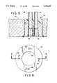
- each coupling 24is joined with a tube member 29 which extends from the respective coupling element 24 to a position closely adjacent the second end of the housing 12.
- the tubular element 29can be an integral part of the associated coupling 24 or it can be joined thereto in the manner shown by a slip fit to a locating flange portion 30.
- the juncture between the coupling 24 and the associated tube 28can be bonded or sealed in any convenient manner, if desired.
Landscapes
- Engineering & Computer Science (AREA)
- General Engineering & Computer Science (AREA)
- Mechanical Engineering (AREA)
- Health & Medical Sciences (AREA)
- Public Health (AREA)
- Business, Economics & Management (AREA)
- Emergency Management (AREA)
- Building Environments (AREA)
Abstract
Description
Claims (4)
Priority Applications (2)
| Application Number | Priority Date | Filing Date | Title |
|---|---|---|---|
| US08/116,719US5390465A (en) | 1993-03-11 | 1993-09-03 | Passthrough device with firestop |
| CA 2130059CA2130059C (en) | 1993-09-03 | 1994-08-12 | Passthrough device with firestop |
Applications Claiming Priority (2)
| Application Number | Priority Date | Filing Date | Title |
|---|---|---|---|
| US08/029,685US5417019A (en) | 1993-03-11 | 1993-03-11 | Passthrough device with firestop |
| US08/116,719US5390465A (en) | 1993-03-11 | 1993-09-03 | Passthrough device with firestop |
Related Parent Applications (1)
| Application Number | Title | Priority Date | Filing Date |
|---|---|---|---|
| US08/029,685Continuation-In-PartUS5417019A (en) | 1993-03-11 | 1993-03-11 | Passthrough device with firestop |
Publications (1)
| Publication Number | Publication Date |
|---|---|
| US5390465Atrue US5390465A (en) | 1995-02-21 |
Family
ID=46202271
Family Applications (1)
| Application Number | Title | Priority Date | Filing Date |
|---|---|---|---|
| US08/116,719Expired - Fee RelatedUS5390465A (en) | 1993-03-11 | 1993-09-03 | Passthrough device with firestop |
Country Status (1)
| Country | Link |
|---|---|
| US (1) | US5390465A (en) |
Cited By (68)
| Publication number | Priority date | Publication date | Assignee | Title |
|---|---|---|---|---|
| WO1996007043A1 (en)* | 1994-08-31 | 1996-03-07 | Quincey, Steven, John | Supports |
| US6305133B1 (en) | 1999-08-05 | 2001-10-23 | Kenneth R. Cornwall | Self sealing firestop coupling assembly |
| US6405502B1 (en) | 2000-05-18 | 2002-06-18 | Kenneth R. Cornwall | Firestop assembly comprising intumescent material within a metal extension mounted on the inner surface of a plastic coupling |
| US20030009961A1 (en)* | 2001-07-12 | 2003-01-16 | 3M Innovative Properties Company | Pass-through firestop device |
| WO2003006865A1 (en) | 2001-07-12 | 2003-01-23 | 3M Innovative Properties Company | Pass-through firestop device |
| US20030014924A1 (en)* | 2001-07-18 | 2003-01-23 | Yazaki Corporation | Grommet |
| EP1293714A1 (en)* | 2001-09-17 | 2003-03-19 | HILTI Aktiengesellschaft | Embeddable, intumescent pipe transit |
| US6615860B2 (en)* | 2001-01-16 | 2003-09-09 | Royal Group Technologies Limited | Fire block conduit coupler |
| WO2003089828A1 (en) | 2002-04-15 | 2003-10-30 | 3M Innovative Properties Company | Pass-through firestop device |
| US20030213211A1 (en)* | 2001-10-31 | 2003-11-20 | W.R. Grace & Co.-Conn. | In situ molded thermal barriers |
| US20040016190A1 (en)* | 2002-07-26 | 2004-01-29 | Radke Duwayne C. | Modular device to create a passage through a partition |
| US20040045234A1 (en)* | 2001-10-31 | 2004-03-11 | W.R. Grace & Co.-Conn. | In situ molded thermal barriers |
| US20040104498A1 (en)* | 2002-12-02 | 2004-06-03 | David Schneider | Tubular sleeve insert for creating a void in precast concrete |
| US20040111992A1 (en)* | 2002-12-06 | 2004-06-17 | Aztec Concrete Accessories, Inc. | Concrete dowel void former |
| US20040211138A1 (en)* | 2001-01-16 | 2004-10-28 | Sakno Michael P. | Firestop coupling for penetration of building separations |
| US20060117677A1 (en)* | 2004-12-06 | 2006-06-08 | Hilti Aktiengesellschaft | Leadthrough system |
| US20060137293A1 (en)* | 2004-12-20 | 2006-06-29 | Klein James A | Head-of-wall fireblocks and related wall assemblies |
| US20060265980A1 (en)* | 2005-05-24 | 2006-11-30 | Vaughan James A | Conduit with adjustable length and fire collar |
| US20070138789A1 (en)* | 2005-12-21 | 2007-06-21 | Hilti Aktiengesellscahft | Leadthrough for a constructional component |
| US20080135285A1 (en)* | 2006-12-07 | 2008-06-12 | Thomas & Betts International, Inc. | Intumescent Cover For A Poke-Through Assembly |
| US20090049781A1 (en)* | 2007-08-22 | 2009-02-26 | California Expanded Metal Products Company | Fire-rated wall construction product |
| US20090178369A1 (en)* | 2008-01-16 | 2009-07-16 | California Expanded Metal Products Company | Exterior wall construction product |
| US20090178363A1 (en)* | 2008-01-16 | 2009-07-16 | California Expanded Metal Products Company | Exterior wall construction product |
| US20090320392A1 (en)* | 2006-07-25 | 2009-12-31 | Deutsche Rockwool Mineralwoll Gmbh & Co. Ohg | Wall leadthrough for leading a line through a building wall |
| US20100024338A1 (en)* | 2008-07-30 | 2010-02-04 | 3M Innovative Properties Company | Pass-through firestop apparatus and methods |
| US7694474B1 (en) | 2006-01-26 | 2010-04-13 | Specified Technologies Inc. | Method and apparatus for firestopping around a water closet drain pipe in a vertical floor opening |
| US20100126092A1 (en)* | 2007-08-22 | 2010-05-27 | Pilz Don A | Fire-rated wall construction product |
| US20110005155A1 (en)* | 2007-08-06 | 2011-01-13 | California Expanded Metal Products Company | Two-piece track system |
| US20110011019A1 (en)* | 2009-07-14 | 2011-01-20 | Specified Technologies Inc. | Firestopping sealing means for use with gypsum wallboard in head-of-wall construction |
| WO2011032211A1 (en)* | 2009-09-21 | 2011-03-24 | Ig6 Pty Ltd | Improved fire collars |
| US20110088342A1 (en)* | 2009-10-15 | 2011-04-21 | Specified Technologies Inc. | Firestopping bushing |
| US8001737B1 (en)* | 2007-12-18 | 2011-08-23 | Mhubbard 09, Llc | Corrugated deck sealing devices, apparatus, systems and methods of installation |
| US20120014048A1 (en)* | 2010-07-14 | 2012-01-19 | Robert Bosch Gmbh | Cable Kink Protection Unit and Method for Producing Same |
| USD657232S1 (en) | 2010-08-17 | 2012-04-10 | Specified Technologies, Inc. | Firestopping bushing made from two separate identical parts |
| US20130037281A1 (en)* | 2011-08-10 | 2013-02-14 | Victaulic Company | Sprinkler System and Installation |
| US8555566B2 (en) | 2007-08-06 | 2013-10-15 | California Expanded Metal Products Company | Two-piece track system |
| US8590231B2 (en) | 2012-01-20 | 2013-11-26 | California Expanded Metal Products Company | Fire-rated joint system |
| US8595999B1 (en) | 2012-07-27 | 2013-12-03 | California Expanded Metal Products Company | Fire-rated joint system |
| US20140020315A1 (en)* | 2012-07-23 | 2014-01-23 | Hilti Aktiengesellschaft | Assembly for a line conduit |
| US8640415B2 (en) | 2010-04-08 | 2014-02-04 | California Expanded Metal Products Company | Fire-rated wall construction product |
| US8671632B2 (en) | 2009-09-21 | 2014-03-18 | California Expanded Metal Products Company | Wall gap fire block device, system and method |
| US8793947B2 (en) | 2010-04-08 | 2014-08-05 | California Expanded Metal Products Company | Fire-rated wall construction product |
| US9045899B2 (en) | 2012-01-20 | 2015-06-02 | California Expanded Metal Products Company | Fire-rated joint system |
| US20150345115A1 (en)* | 2012-06-29 | 2015-12-03 | Stephen Johnson | Waterproofing water combinations |
| US20160123002A1 (en)* | 2013-07-17 | 2016-05-05 | Hilti Aktiengesellschaft | Through-Penetration Device, Method for Manufacturing a Through-Penetration Device, and Method for Installing a Through-Penetration Device |
| US9523193B2 (en) | 2012-01-20 | 2016-12-20 | California Expanded Metal Products Company | Fire-rated joint system |
| US9683364B2 (en) | 2010-04-08 | 2017-06-20 | California Expanded Metal Products Company | Fire-rated wall construction product |
| US9752318B2 (en) | 2015-01-16 | 2017-09-05 | California Expanded Metal Products Company | Fire blocking reveal |
| US9879421B2 (en) | 2014-10-06 | 2018-01-30 | California Expanded Metal Products Company | Fire-resistant angle and related assemblies |
| US9909298B2 (en) | 2015-01-27 | 2018-03-06 | California Expanded Metal Products Company | Header track with stud retention feature |
| US10000923B2 (en) | 2015-01-16 | 2018-06-19 | California Expanded Metal Products Company | Fire blocking reveal |
| US10077550B2 (en) | 2012-01-20 | 2018-09-18 | California Expanded Metal Products Company | Fire-rated joint system |
| US10184246B2 (en) | 2010-04-08 | 2019-01-22 | California Expanded Metal Products Company | Fire-rated wall construction product |
| US10253512B2 (en) | 2015-09-09 | 2019-04-09 | Walk Safe Innovations, Llc | Rough-in box for creating penetrations in poured concrete flooring and method of use |
| US20190290947A1 (en)* | 2016-05-20 | 2019-09-26 | Specified Technologies Inc. | Bus duct firestop system |
| US20190360195A1 (en)* | 2018-03-15 | 2019-11-28 | California Expanded Metal Products Company | Fire-rated joint component and wall assembly |
| US10563399B2 (en)* | 2007-08-06 | 2020-02-18 | California Expanded Metal Products Company | Two-piece track system |
| US10619347B2 (en) | 2007-08-22 | 2020-04-14 | California Expanded Metal Products Company | Fire-rated wall and ceiling system |
| US10689842B2 (en) | 2018-03-15 | 2020-06-23 | California Expanded Metal Products Company | Multi-layer fire-rated joint component |
| US10914065B2 (en) | 2019-01-24 | 2021-02-09 | California Expanded Metal Products Company | Wall joint or sound block component and wall assemblies |
| US11111666B2 (en) | 2018-08-16 | 2021-09-07 | California Expanded Metal Products Company | Fire or sound blocking components and wall assemblies with fire or sound blocking components |
| US11162259B2 (en) | 2018-04-30 | 2021-11-02 | California Expanded Metal Products Company | Mechanically fastened firestop flute plug |
| US11186986B2 (en)* | 2018-09-28 | 2021-11-30 | Reliance Worldwide Corporation | Sleeve assembly for a poured concrete deck |
| US11207551B2 (en) | 2018-08-23 | 2021-12-28 | Victaulic Company | Dry sprinkler assembly |
| US20220063132A1 (en)* | 2020-08-25 | 2022-03-03 | Thomas Fong | Multi-Use Donut for Piping Installation |
| US11268274B2 (en) | 2019-03-04 | 2022-03-08 | California Expanded Metal Products Company | Two-piece deflection drift angle |
| US11920343B2 (en) | 2019-12-02 | 2024-03-05 | Cemco, Llc | Fire-rated wall joint component and related assemblies |
| US12215498B2 (en) | 2012-01-20 | 2025-02-04 | Cemco, Llc | Fire-rated joint system |
Citations (36)
| Publication number | Priority date | Publication date | Assignee | Title |
|---|---|---|---|---|
| US3995102A (en)* | 1974-01-25 | 1976-11-30 | Raceway Components, Inc. | Insert device for cables |
| US4061334A (en)* | 1975-01-21 | 1977-12-06 | Tomy Kogyo Co., Inc. | Disc bowling game |
| US4109423A (en)* | 1976-04-14 | 1978-08-29 | Pont-A-Mousson S.A. | Fire-proof device for a tube of fusible material which extends through a wall |
| US4136707A (en)* | 1976-08-31 | 1979-01-30 | Pont-A-Mousson S.A. | Fire-resisting device for piping extending through a wall |
| US4221092A (en)* | 1975-11-04 | 1980-09-09 | Ici Australia Limited | Sleeve |
| US4307546A (en)* | 1979-09-07 | 1981-12-29 | Geberit Ag | Fire retardant partitioning for openings for plastic pipe lines |
| US4364210A (en)* | 1980-05-29 | 1982-12-21 | Minnesota Mining And Manufacturing Company | Fire barrier device |
| US4419535A (en)* | 1981-07-31 | 1983-12-06 | Hara Robert J O | Multi-cable conduit for floors and walls |
| US4467577A (en)* | 1980-05-29 | 1984-08-28 | Minnesota Mining And Manufacturing Company | Intumescent fire barrier material laminated with restraining layer |
| US4529467A (en)* | 1983-10-25 | 1985-07-16 | Ppg Industries, Inc. | Fire protective intumescent mastic composition and method employing same |
| US4538389A (en)* | 1981-05-18 | 1985-09-03 | Intellectual Trade Cy S.A. | Fire-break |
| US4559745A (en)* | 1983-12-22 | 1985-12-24 | Fire Research Pty. Limited | Devices for the fire stopping of plastics pipes |
| US4583565A (en)* | 1983-11-25 | 1986-04-22 | Cornwall Kenneth R | Firestop stack fitting and coupling combination |
| US4587082A (en)* | 1980-08-08 | 1986-05-06 | Hochtemperatur-Reaktorbau Gmbh | Passage through the wall of a reinforced concrete pressure vessel |
| US4642956A (en)* | 1985-05-01 | 1987-02-17 | Gerold Harbeke | Fire-retardant fluid coupling assembly and method |
| US4646486A (en)* | 1984-02-28 | 1987-03-03 | Werner Hauff | Flame-retarding wall feedthrough fitting |
| US4669759A (en)* | 1986-01-14 | 1987-06-02 | Harbeke Gerold J | Fire-stop stack fitting and method of using same |
| US4724858A (en)* | 1987-08-05 | 1988-02-16 | Cornwall Kenneth R | Firestop stack fitting |
| US4748787A (en)* | 1986-07-02 | 1988-06-07 | Harbeke Gerold J | Pipe flange fire-proofing kit and process |
| US4796401A (en)* | 1985-08-06 | 1989-01-10 | Fire Research Pty., Limited | Composite fire stop device |
| US4804160A (en)* | 1987-09-01 | 1989-02-14 | Harbeke Gerold J | Automatically-releasable pipe-attachment device |
| US4823527A (en)* | 1985-12-12 | 1989-04-25 | Harbeke Gerold J | Plumbing concrete form accessory |
| US4848043A (en)* | 1988-09-14 | 1989-07-18 | Harbeke Gerold J | Under floor fire stop coupling and method |
| US4850385A (en)* | 1988-11-10 | 1989-07-25 | Harbeke Gerold J | Fire stop pipe coupling adaptor |
| US4877216A (en)* | 1987-11-03 | 1989-10-31 | Harbeke Gerold J | Automatically-releasable pipe-attachment device |
| US4882886A (en)* | 1987-09-01 | 1989-11-28 | Harbeke Gerold J | Automatically-releasable pipe attachment device |
| US4888925A (en)* | 1987-11-03 | 1989-12-26 | Harbeke Gerold J | Fire-retardant fluid coupling assembly and method |
| US4894966A (en)* | 1988-11-08 | 1990-01-23 | Bailey Paul R | Fire stopping apparatus |
| US4901488A (en)* | 1987-11-12 | 1990-02-20 | The Furukawa Electric Co., Ltd. | Fire/smoke protection structure for a plastic pipe or cable channel portion in a floor or wall |
| US4916800A (en)* | 1987-11-03 | 1990-04-17 | Harbeke Gerold J | Fire-retardant fluid coupling assembly and method |
| US4918761A (en)* | 1988-06-02 | 1990-04-24 | Harbeke Gerold J | Method of using a toilet-flange cast-in mount |
| US4951442A (en)* | 1989-08-31 | 1990-08-28 | Msp Products, Inc. | Method for constructing fire-stop collar assembly |
| US4953235A (en)* | 1988-06-10 | 1990-09-04 | Cornwall Kenneth R | Trap fitting assembly |
| US5058341A (en)* | 1989-08-31 | 1991-10-22 | Msp Products, Inc. | Method for constructing fire-stop collar assembly and apparatus thereof |
| US5155957A (en)* | 1991-01-14 | 1992-10-20 | National Improvement Company, Inc. | Fire safety device |
| US5309688A (en)* | 1989-03-03 | 1994-05-10 | Paul Robertson | Concrete slab penetration unit for pipes |
- 1993
- 1993-09-03USUS08/116,719patent/US5390465A/ennot_activeExpired - Fee Related
Patent Citations (37)
| Publication number | Priority date | Publication date | Assignee | Title |
|---|---|---|---|---|
| US3995102B1 (en)* | 1974-01-25 | 1985-10-08 | ||
| US3995102A (en)* | 1974-01-25 | 1976-11-30 | Raceway Components, Inc. | Insert device for cables |
| US4061334A (en)* | 1975-01-21 | 1977-12-06 | Tomy Kogyo Co., Inc. | Disc bowling game |
| US4221092A (en)* | 1975-11-04 | 1980-09-09 | Ici Australia Limited | Sleeve |
| US4109423A (en)* | 1976-04-14 | 1978-08-29 | Pont-A-Mousson S.A. | Fire-proof device for a tube of fusible material which extends through a wall |
| US4136707A (en)* | 1976-08-31 | 1979-01-30 | Pont-A-Mousson S.A. | Fire-resisting device for piping extending through a wall |
| US4307546A (en)* | 1979-09-07 | 1981-12-29 | Geberit Ag | Fire retardant partitioning for openings for plastic pipe lines |
| US4364210A (en)* | 1980-05-29 | 1982-12-21 | Minnesota Mining And Manufacturing Company | Fire barrier device |
| US4467577A (en)* | 1980-05-29 | 1984-08-28 | Minnesota Mining And Manufacturing Company | Intumescent fire barrier material laminated with restraining layer |
| US4587082A (en)* | 1980-08-08 | 1986-05-06 | Hochtemperatur-Reaktorbau Gmbh | Passage through the wall of a reinforced concrete pressure vessel |
| US4538389A (en)* | 1981-05-18 | 1985-09-03 | Intellectual Trade Cy S.A. | Fire-break |
| US4419535A (en)* | 1981-07-31 | 1983-12-06 | Hara Robert J O | Multi-cable conduit for floors and walls |
| US4529467A (en)* | 1983-10-25 | 1985-07-16 | Ppg Industries, Inc. | Fire protective intumescent mastic composition and method employing same |
| US4583565A (en)* | 1983-11-25 | 1986-04-22 | Cornwall Kenneth R | Firestop stack fitting and coupling combination |
| US4559745A (en)* | 1983-12-22 | 1985-12-24 | Fire Research Pty. Limited | Devices for the fire stopping of plastics pipes |
| US4646486A (en)* | 1984-02-28 | 1987-03-03 | Werner Hauff | Flame-retarding wall feedthrough fitting |
| US4642956A (en)* | 1985-05-01 | 1987-02-17 | Gerold Harbeke | Fire-retardant fluid coupling assembly and method |
| US4796401A (en)* | 1985-08-06 | 1989-01-10 | Fire Research Pty., Limited | Composite fire stop device |
| US4823527A (en)* | 1985-12-12 | 1989-04-25 | Harbeke Gerold J | Plumbing concrete form accessory |
| US4669759A (en)* | 1986-01-14 | 1987-06-02 | Harbeke Gerold J | Fire-stop stack fitting and method of using same |
| US4748787A (en)* | 1986-07-02 | 1988-06-07 | Harbeke Gerold J | Pipe flange fire-proofing kit and process |
| US4724858A (en)* | 1987-08-05 | 1988-02-16 | Cornwall Kenneth R | Firestop stack fitting |
| US4804160A (en)* | 1987-09-01 | 1989-02-14 | Harbeke Gerold J | Automatically-releasable pipe-attachment device |
| US4882886A (en)* | 1987-09-01 | 1989-11-28 | Harbeke Gerold J | Automatically-releasable pipe attachment device |
| US4916800A (en)* | 1987-11-03 | 1990-04-17 | Harbeke Gerold J | Fire-retardant fluid coupling assembly and method |
| US4877216A (en)* | 1987-11-03 | 1989-10-31 | Harbeke Gerold J | Automatically-releasable pipe-attachment device |
| US4888925A (en)* | 1987-11-03 | 1989-12-26 | Harbeke Gerold J | Fire-retardant fluid coupling assembly and method |
| US4901488A (en)* | 1987-11-12 | 1990-02-20 | The Furukawa Electric Co., Ltd. | Fire/smoke protection structure for a plastic pipe or cable channel portion in a floor or wall |
| US4918761A (en)* | 1988-06-02 | 1990-04-24 | Harbeke Gerold J | Method of using a toilet-flange cast-in mount |
| US4953235A (en)* | 1988-06-10 | 1990-09-04 | Cornwall Kenneth R | Trap fitting assembly |
| US4848043A (en)* | 1988-09-14 | 1989-07-18 | Harbeke Gerold J | Under floor fire stop coupling and method |
| US4894966A (en)* | 1988-11-08 | 1990-01-23 | Bailey Paul R | Fire stopping apparatus |
| US4850385A (en)* | 1988-11-10 | 1989-07-25 | Harbeke Gerold J | Fire stop pipe coupling adaptor |
| US5309688A (en)* | 1989-03-03 | 1994-05-10 | Paul Robertson | Concrete slab penetration unit for pipes |
| US4951442A (en)* | 1989-08-31 | 1990-08-28 | Msp Products, Inc. | Method for constructing fire-stop collar assembly |
| US5058341A (en)* | 1989-08-31 | 1991-10-22 | Msp Products, Inc. | Method for constructing fire-stop collar assembly and apparatus thereof |
| US5155957A (en)* | 1991-01-14 | 1992-10-20 | National Improvement Company, Inc. | Fire safety device |
Cited By (149)
| Publication number | Priority date | Publication date | Assignee | Title |
|---|---|---|---|---|
| WO1996007043A1 (en)* | 1994-08-31 | 1996-03-07 | Quincey, Steven, John | Supports |
| US6305133B1 (en) | 1999-08-05 | 2001-10-23 | Kenneth R. Cornwall | Self sealing firestop coupling assembly |
| US6336297B1 (en) | 1999-08-05 | 2002-01-08 | Kenneth R. Cornwall | Self sealing firestop coupling assembly |
| US6405502B1 (en) | 2000-05-18 | 2002-06-18 | Kenneth R. Cornwall | Firestop assembly comprising intumescent material within a metal extension mounted on the inner surface of a plastic coupling |
| US6470635B2 (en) | 2000-05-18 | 2002-10-29 | Kenneth R. Cornwall | Coupling assembly with intumescent material |
| US6615860B2 (en)* | 2001-01-16 | 2003-09-09 | Royal Group Technologies Limited | Fire block conduit coupler |
| US20040211138A1 (en)* | 2001-01-16 | 2004-10-28 | Sakno Michael P. | Firestop coupling for penetration of building separations |
| US20030009961A1 (en)* | 2001-07-12 | 2003-01-16 | 3M Innovative Properties Company | Pass-through firestop device |
| US7080486B2 (en)* | 2001-07-12 | 2006-07-25 | 3M Innovative Properties Company | Pass-through firestop device |
| WO2003006865A1 (en) | 2001-07-12 | 2003-01-23 | 3M Innovative Properties Company | Pass-through firestop device |
| US20030014924A1 (en)* | 2001-07-18 | 2003-01-23 | Yazaki Corporation | Grommet |
| US6941714B2 (en)* | 2001-07-18 | 2005-09-13 | Yazaki Corporation | Grommet |
| US6643985B2 (en) | 2001-09-17 | 2003-11-11 | Hilti Aktiengesellschaft | Tubular lead-in fixture |
| AU2002300828B2 (en)* | 2001-09-17 | 2007-05-10 | Hilti Aktiengesellschaft | Tubular lead-in fixture |
| EP1293714A1 (en)* | 2001-09-17 | 2003-03-19 | HILTI Aktiengesellschaft | Embeddable, intumescent pipe transit |
| US7152385B2 (en) | 2001-10-31 | 2006-12-26 | W.R. Grace & Co.-Conn. | In situ molded thermal barriers |
| US6698146B2 (en) | 2001-10-31 | 2004-03-02 | W. R. Grace & Co.-Conn. | In situ molded thermal barriers |
| US20040045234A1 (en)* | 2001-10-31 | 2004-03-11 | W.R. Grace & Co.-Conn. | In situ molded thermal barriers |
| US20030213211A1 (en)* | 2001-10-31 | 2003-11-20 | W.R. Grace & Co.-Conn. | In situ molded thermal barriers |
| US7043880B2 (en) | 2001-10-31 | 2006-05-16 | W. R. Grace & Co.-Conn. | In situ molded thermal barriers |
| US6783345B2 (en) | 2001-10-31 | 2004-08-31 | W.R. Grace & Co.-Conn | In situ molded thermal barriers |
| US6694684B2 (en)* | 2002-04-15 | 2004-02-24 | 3M Innovative Properties Company | Pass through firestop device |
| WO2003089828A1 (en) | 2002-04-15 | 2003-10-30 | 3M Innovative Properties Company | Pass-through firestop device |
| US20040016190A1 (en)* | 2002-07-26 | 2004-01-29 | Radke Duwayne C. | Modular device to create a passage through a partition |
| US20040104498A1 (en)* | 2002-12-02 | 2004-06-03 | David Schneider | Tubular sleeve insert for creating a void in precast concrete |
| US20090139179A1 (en)* | 2002-12-06 | 2009-06-04 | Dayton Superior Corporation | Concrete Dowel Void Former |
| US20040111992A1 (en)* | 2002-12-06 | 2004-06-17 | Aztec Concrete Accessories, Inc. | Concrete dowel void former |
| US7887735B2 (en) | 2002-12-06 | 2011-02-15 | Dayton Superior Corporation | Method of forming a void in a mass of concrete using a dowel void former |
| US7487949B2 (en)* | 2002-12-06 | 2009-02-10 | Dayton Superior Corporation | Concrete dowel void former |
| US20060117677A1 (en)* | 2004-12-06 | 2006-06-08 | Hilti Aktiengesellschaft | Leadthrough system |
| US20060137293A1 (en)* | 2004-12-20 | 2006-06-29 | Klein James A | Head-of-wall fireblocks and related wall assemblies |
| US8181404B2 (en)* | 2004-12-20 | 2012-05-22 | James Alan Klein | Head-of-wall fireblocks and related wall assemblies |
| US20060265980A1 (en)* | 2005-05-24 | 2006-11-30 | Vaughan James A | Conduit with adjustable length and fire collar |
| US7581362B2 (en) | 2005-05-24 | 2009-09-01 | Metis Holdings | Conduit with adjustable length and fire collar |
| US20070138789A1 (en)* | 2005-12-21 | 2007-06-21 | Hilti Aktiengesellscahft | Leadthrough for a constructional component |
| US7694474B1 (en) | 2006-01-26 | 2010-04-13 | Specified Technologies Inc. | Method and apparatus for firestopping around a water closet drain pipe in a vertical floor opening |
| US8438804B2 (en)* | 2006-07-25 | 2013-05-14 | Deutsche Rockwoll Mineralwoll Gmbh & Co. Ohg | Wall leadthrough for leading a line through a building wall |
| US20090320392A1 (en)* | 2006-07-25 | 2009-12-31 | Deutsche Rockwool Mineralwoll Gmbh & Co. Ohg | Wall leadthrough for leading a line through a building wall |
| US20080135285A1 (en)* | 2006-12-07 | 2008-06-12 | Thomas & Betts International, Inc. | Intumescent Cover For A Poke-Through Assembly |
| US7847199B2 (en) | 2006-12-07 | 2010-12-07 | Thomas & Betts International, Inc. | Intumescent cover for a poke-through assembly |
| US7674990B2 (en) | 2006-12-07 | 2010-03-09 | Thomas & Betts International, Inc. | Intumescent cover for a poke-through assembly |
| US11041306B2 (en) | 2007-08-06 | 2021-06-22 | California Expanded Metal Products Company | Two-piece track system |
| US11560712B2 (en) | 2007-08-06 | 2023-01-24 | Cemco, Llc | Two-piece track system |
| US20110005155A1 (en)* | 2007-08-06 | 2011-01-13 | California Expanded Metal Products Company | Two-piece track system |
| US10563399B2 (en)* | 2007-08-06 | 2020-02-18 | California Expanded Metal Products Company | Two-piece track system |
| US11773587B2 (en) | 2007-08-06 | 2023-10-03 | Cemco, Llc | Two-piece track system |
| US10227775B2 (en) | 2007-08-06 | 2019-03-12 | California Expanded Metal Products Company | Two-piece track system |
| US9995039B2 (en) | 2007-08-06 | 2018-06-12 | California Expanded Metal Products Company | Two-piece track system |
| US9739054B2 (en)* | 2007-08-06 | 2017-08-22 | California Expanded Metal Products Company | Two-piece track system |
| US9290934B2 (en)* | 2007-08-06 | 2016-03-22 | California Expanded Metal Products Company | Two-piece track system |
| US8973319B2 (en) | 2007-08-06 | 2015-03-10 | California Expanded Metal Products Company | Two-piece track system |
| US8555566B2 (en) | 2007-08-06 | 2013-10-15 | California Expanded Metal Products Company | Two-piece track system |
| US12252881B2 (en) | 2007-08-06 | 2025-03-18 | Cemco, Llc | Two-piece track system |
| US8132376B2 (en) | 2007-08-06 | 2012-03-13 | California Expanded Metal Products Company | Two-piece track system |
| US10619347B2 (en) | 2007-08-22 | 2020-04-14 | California Expanded Metal Products Company | Fire-rated wall and ceiling system |
| US11466449B2 (en) | 2007-08-22 | 2022-10-11 | California Expanded Metal Products Company | Fire-rated wall and ceiling system |
| US9637914B2 (en) | 2007-08-22 | 2017-05-02 | California Expanded Metal Products Company | Fire-rated wall and ceiling system |
| US7950198B2 (en) | 2007-08-22 | 2011-05-31 | California Expanded Metal Products Company | Fire-rated wall construction product |
| US8322094B2 (en) | 2007-08-22 | 2012-12-04 | California Expanded Metal Products Company | Fire-rated wall and ceiling system |
| US10011983B2 (en) | 2007-08-22 | 2018-07-03 | California Expanded Metal Products Company | Fire-rated wall and ceiling system |
| US9481998B2 (en) | 2007-08-22 | 2016-11-01 | California Expanded Metal Products Company | Fire-rated wall and ceiling system |
| US11802404B2 (en) | 2007-08-22 | 2023-10-31 | Cemco, Llc | Fire-rated wall and ceiling system |
| US20090049781A1 (en)* | 2007-08-22 | 2009-02-26 | California Expanded Metal Products Company | Fire-rated wall construction product |
| US9739052B2 (en) | 2007-08-22 | 2017-08-22 | California Expanded Metal Products Company | Fire-rated wall and ceiling system |
| US8087205B2 (en) | 2007-08-22 | 2012-01-03 | California Expanded Metal Products Company | Fire-rated wall construction product |
| US20100126092A1 (en)* | 2007-08-22 | 2010-05-27 | Pilz Don A | Fire-rated wall construction product |
| US9127454B2 (en) | 2007-08-22 | 2015-09-08 | California Expanded Metal Products Company | Fire-rated wall and ceiling system |
| US10214901B2 (en) | 2007-08-22 | 2019-02-26 | California Expanded Metal Products Company | Fire-rated wall and ceiling system |
| US8001737B1 (en)* | 2007-12-18 | 2011-08-23 | Mhubbard 09, Llc | Corrugated deck sealing devices, apparatus, systems and methods of installation |
| US8499512B2 (en) | 2008-01-16 | 2013-08-06 | California Expanded Metal Products Company | Exterior wall construction product |
| US20090178363A1 (en)* | 2008-01-16 | 2009-07-16 | California Expanded Metal Products Company | Exterior wall construction product |
| US8281552B2 (en) | 2008-01-16 | 2012-10-09 | California Expanded Metal Products Company | Exterior wall construction product |
| US20090178369A1 (en)* | 2008-01-16 | 2009-07-16 | California Expanded Metal Products Company | Exterior wall construction product |
| US8146305B2 (en)* | 2008-07-30 | 2012-04-03 | 3M Innovative Properties Company | Pass-through firestop apparatus and methods |
| US8024900B2 (en)* | 2008-07-30 | 2011-09-27 | 3M Innovative Properties Company | Pass-through firestop apparatus and methods |
| US20100024338A1 (en)* | 2008-07-30 | 2010-02-04 | 3M Innovative Properties Company | Pass-through firestop apparatus and methods |
| US20110011019A1 (en)* | 2009-07-14 | 2011-01-20 | Specified Technologies Inc. | Firestopping sealing means for use with gypsum wallboard in head-of-wall construction |
| US8375666B2 (en) | 2009-07-14 | 2013-02-19 | Specified Technologies Inc. | Firestopping sealing means for use with gypsum wallboard in head-of-wall construction |
| US8584415B2 (en) | 2009-07-14 | 2013-11-19 | Specified Technologies Inc. | Firestopping sealing means for use with gypsum wallboard in head-of-wall construction |
| US11896859B2 (en) | 2009-09-21 | 2024-02-13 | Cemco, Llc | Wall gap fire block device, system and method |
| WO2011032211A1 (en)* | 2009-09-21 | 2011-03-24 | Ig6 Pty Ltd | Improved fire collars |
| US10406389B2 (en) | 2009-09-21 | 2019-09-10 | California Expanded Metal Products Company | Wall gap fire block device, system and method |
| US9371644B2 (en) | 2009-09-21 | 2016-06-21 | California Expanded Metal Products Company | Wall gap fire block device, system and method |
| US9931527B2 (en) | 2009-09-21 | 2018-04-03 | California Expanded Metal Products Company | Wall gap fire block device, system and method |
| US8938922B2 (en) | 2009-09-21 | 2015-01-27 | California Expanded Metal Products Company | Wall gap fire block device, system and method |
| US11141613B2 (en) | 2009-09-21 | 2021-10-12 | California Expanded Metal Products Company | Wall gap fire block device, system and method |
| US9616259B2 (en) | 2009-09-21 | 2017-04-11 | California Expanded Metal Products Company | Wall gap fire block device, system and method |
| US8671632B2 (en) | 2009-09-21 | 2014-03-18 | California Expanded Metal Products Company | Wall gap fire block device, system and method |
| US8397452B2 (en) | 2009-10-15 | 2013-03-19 | Specified Technologies Inc. | Firestopping bushing |
| US20110088342A1 (en)* | 2009-10-15 | 2011-04-21 | Specified Technologies Inc. | Firestopping bushing |
| US12428836B2 (en) | 2010-04-08 | 2025-09-30 | Cemco, Llc | Fire-rated wall construction product |
| US11905705B2 (en) | 2010-04-08 | 2024-02-20 | Cemco, Llc | Fire-rated wall construction product |
| US10184246B2 (en) | 2010-04-08 | 2019-01-22 | California Expanded Metal Products Company | Fire-rated wall construction product |
| US11060283B2 (en) | 2010-04-08 | 2021-07-13 | California Expanded Metal Products Company | Fire-rated wall construction product |
| US9683364B2 (en) | 2010-04-08 | 2017-06-20 | California Expanded Metal Products Company | Fire-rated wall construction product |
| US9290932B2 (en) | 2010-04-08 | 2016-03-22 | California Expanded Metal Products Company | Fire-rated wall construction product |
| US8793947B2 (en) | 2010-04-08 | 2014-08-05 | California Expanded Metal Products Company | Fire-rated wall construction product |
| US8640415B2 (en) | 2010-04-08 | 2014-02-04 | California Expanded Metal Products Company | Fire-rated wall construction product |
| US20120014048A1 (en)* | 2010-07-14 | 2012-01-19 | Robert Bosch Gmbh | Cable Kink Protection Unit and Method for Producing Same |
| US8586879B2 (en)* | 2010-07-14 | 2013-11-19 | Robert Bosch Gmbh | Cable kink protection unit and method for producing same |
| USD657232S1 (en) | 2010-08-17 | 2012-04-10 | Specified Technologies, Inc. | Firestopping bushing made from two separate identical parts |
| AU2012294921B2 (en)* | 2011-08-10 | 2016-12-01 | Victaulic Company | Sprinkler system and installation |
| US20130037281A1 (en)* | 2011-08-10 | 2013-02-14 | Victaulic Company | Sprinkler System and Installation |
| US9511248B2 (en)* | 2011-08-10 | 2016-12-06 | Victaulic Company | Sprinkler system and installation |
| US10077550B2 (en) | 2012-01-20 | 2018-09-18 | California Expanded Metal Products Company | Fire-rated joint system |
| US12215498B2 (en) | 2012-01-20 | 2025-02-04 | Cemco, Llc | Fire-rated joint system |
| US10246871B2 (en) | 2012-01-20 | 2019-04-02 | California Expanded Metal Products Company | Fire-rated joint system |
| US10900223B2 (en) | 2012-01-20 | 2021-01-26 | California Expanded Metal Products Company | Fire-rated joint system |
| US9045899B2 (en) | 2012-01-20 | 2015-06-02 | California Expanded Metal Products Company | Fire-rated joint system |
| US11898346B2 (en) | 2012-01-20 | 2024-02-13 | Cemco, Llc | Fire-rated joint system |
| US9523193B2 (en) | 2012-01-20 | 2016-12-20 | California Expanded Metal Products Company | Fire-rated joint system |
| US8590231B2 (en) | 2012-01-20 | 2013-11-26 | California Expanded Metal Products Company | Fire-rated joint system |
| US9458628B2 (en) | 2012-01-20 | 2016-10-04 | California Expanded Metal Products Company | Fire-rated joint system |
| US20150345115A1 (en)* | 2012-06-29 | 2015-12-03 | Stephen Johnson | Waterproofing water combinations |
| US9772051B2 (en) | 2012-06-29 | 2017-09-26 | Stephen Johnson | Waterproofing water combinations |
| US9074367B2 (en)* | 2012-07-23 | 2015-07-07 | Hilti Aktiengesellschaft | Assembly for a line conduit |
| US20140020315A1 (en)* | 2012-07-23 | 2014-01-23 | Hilti Aktiengesellschaft | Assembly for a line conduit |
| US8595999B1 (en) | 2012-07-27 | 2013-12-03 | California Expanded Metal Products Company | Fire-rated joint system |
| US20160123002A1 (en)* | 2013-07-17 | 2016-05-05 | Hilti Aktiengesellschaft | Through-Penetration Device, Method for Manufacturing a Through-Penetration Device, and Method for Installing a Through-Penetration Device |
| US9995037B2 (en)* | 2013-07-17 | 2018-06-12 | Hilti Aktiengesellschaft | Through-penetration device, method for manufacturing a through-penetration device, and method for installing a through-penetration device |
| US9879421B2 (en) | 2014-10-06 | 2018-01-30 | California Expanded Metal Products Company | Fire-resistant angle and related assemblies |
| US9752318B2 (en) | 2015-01-16 | 2017-09-05 | California Expanded Metal Products Company | Fire blocking reveal |
| US10000923B2 (en) | 2015-01-16 | 2018-06-19 | California Expanded Metal Products Company | Fire blocking reveal |
| US9909298B2 (en) | 2015-01-27 | 2018-03-06 | California Expanded Metal Products Company | Header track with stud retention feature |
| US10837183B2 (en) | 2015-09-09 | 2020-11-17 | Walk Safe Innovations, Llc | Rough-in box for creating penetrations in poured concrete flooring and method of use |
| US10253512B2 (en) | 2015-09-09 | 2019-04-09 | Walk Safe Innovations, Llc | Rough-in box for creating penetrations in poured concrete flooring and method of use |
| US10695599B2 (en)* | 2016-05-20 | 2020-06-30 | Specified Technologies Inc. | Bus duct firestop system |
| US20190290947A1 (en)* | 2016-05-20 | 2019-09-26 | Specified Technologies Inc. | Bus duct firestop system |
| US10689842B2 (en) | 2018-03-15 | 2020-06-23 | California Expanded Metal Products Company | Multi-layer fire-rated joint component |
| US20190360195A1 (en)* | 2018-03-15 | 2019-11-28 | California Expanded Metal Products Company | Fire-rated joint component and wall assembly |
| US11421417B2 (en)* | 2018-03-15 | 2022-08-23 | California Expanded Metal Products Company | Fire-rated joint component and wall assembly |
| US12312802B2 (en) | 2018-03-15 | 2025-05-27 | Cemco, Llc | Fire-rated joint component and wall assembly |
| US10954670B2 (en) | 2018-03-15 | 2021-03-23 | California Expanded Metal Products Company | Multi-layer fire-rated joint component |
| US10753084B2 (en)* | 2018-03-15 | 2020-08-25 | California Expanded Metal Products Company | Fire-rated joint component and wall assembly |
| US11866932B2 (en) | 2018-03-15 | 2024-01-09 | Cemco, Llc | Fire-rated joint component and wall assembly |
| US11933042B2 (en) | 2018-04-30 | 2024-03-19 | Cemco, Llc | Mechanically fastened firestop flute plug |
| US11162259B2 (en) | 2018-04-30 | 2021-11-02 | California Expanded Metal Products Company | Mechanically fastened firestop flute plug |
| US11873636B2 (en) | 2018-08-16 | 2024-01-16 | Cemco, Llc | Fire or sound blocking components and wall assemblies with fire or sound blocking components |
| US11111666B2 (en) | 2018-08-16 | 2021-09-07 | California Expanded Metal Products Company | Fire or sound blocking components and wall assemblies with fire or sound blocking components |
| US11207551B2 (en) | 2018-08-23 | 2021-12-28 | Victaulic Company | Dry sprinkler assembly |
| US11712591B2 (en) | 2018-08-23 | 2023-08-01 | Victaulic Company | Dry sprinkler assembly |
| US11186986B2 (en)* | 2018-09-28 | 2021-11-30 | Reliance Worldwide Corporation | Sleeve assembly for a poured concrete deck |
| US11891800B2 (en) | 2019-01-24 | 2024-02-06 | Cemco, Llc | Wall joint or sound block component and wall assemblies |
| US11280084B2 (en) | 2019-01-24 | 2022-03-22 | California Expanded Metal Prod ucts Company | Wall joint or sound block component and wall assemblies |
| US10914065B2 (en) | 2019-01-24 | 2021-02-09 | California Expanded Metal Products Company | Wall joint or sound block component and wall assemblies |
| US11920344B2 (en) | 2019-03-04 | 2024-03-05 | Cemco, Llc | Two-piece deflection drift angle |
| US11268274B2 (en) | 2019-03-04 | 2022-03-08 | California Expanded Metal Products Company | Two-piece deflection drift angle |
| US11920343B2 (en) | 2019-12-02 | 2024-03-05 | Cemco, Llc | Fire-rated wall joint component and related assemblies |
| US20220063132A1 (en)* | 2020-08-25 | 2022-03-03 | Thomas Fong | Multi-Use Donut for Piping Installation |
Similar Documents
| Publication | Publication Date | Title |
|---|---|---|
| US5390465A (en) | Passthrough device with firestop | |
| US5417019A (en) | Passthrough device with firestop | |
| US5347767A (en) | Fire retardant sleeve | |
| US5953872A (en) | Fire barrier assembly | |
| US4669759A (en) | Fire-stop stack fitting and method of using same | |
| US7080486B2 (en) | Pass-through firestop device | |
| US6349975B1 (en) | Slab plumbing system | |
| US6679015B1 (en) | Hub seal firestop device | |
| AU2003259644B2 (en) | Sealing system | |
| AU2003215394B2 (en) | Pass-through firestop device | |
| US7374210B2 (en) | Hydro penetration prevention sleeve | |
| US4453354A (en) | Pipe support coupling and method of using same | |
| US6336297B1 (en) | Self sealing firestop coupling assembly | |
| US4850385A (en) | Fire stop pipe coupling adaptor | |
| US6161873A (en) | Masonry lead-in fixture | |
| US4488388A (en) | Supporting pipe clamp | |
| US4953235A (en) | Trap fitting assembly | |
| US20040016190A1 (en) | Modular device to create a passage through a partition | |
| US7694474B1 (en) | Method and apparatus for firestopping around a water closet drain pipe in a vertical floor opening | |
| US20020032996A1 (en) | Coupling assembly with intumescent material | |
| JPH09510514A (en) | Fire and smoke spread prevention device | |
| US4804160A (en) | Automatically-releasable pipe-attachment device | |
| US20060265980A1 (en) | Conduit with adjustable length and fire collar | |
| US3904228A (en) | Septic tank tee | |
| US6161564A (en) | Fire transmission prevention system |
Legal Events
| Date | Code | Title | Description |
|---|---|---|---|
| AS | Assignment | Owner name:LAMSON & SESSIONS CO., THE, OHIO Free format text:ASSIGNMENT OF ASSIGNORS INTEREST;ASSIGNOR:RAJECKI, JAMES A.;REEL/FRAME:006688/0594 Effective date:19930903 | |
| FEPP | Fee payment procedure | Free format text:PAYOR NUMBER ASSIGNED (ORIGINAL EVENT CODE: ASPN); ENTITY STATUS OF PATENT OWNER: LARGE ENTITY | |
| FPAY | Fee payment | Year of fee payment:4 | |
| AS | Assignment | Owner name:FACET HOLDING CO., INC., NEW YORK Free format text:ASSIGNMENT OF ASSIGNORS INTEREST;ASSIGNOR:PUROLATOR PRODUCTS COMPANY;REEL/FRAME:009737/0987 Effective date:19990212 | |
| AS | Assignment | Owner name:HARRIS TRUST AND SAVINGS BANK, AS ADMINISTRATIVE A Free format text:COLLATERAL AGREEMENT;ASSIGNOR:LAMSON & SESSIONS CO., THE;REEL/FRAME:011052/0278 Effective date:20000808 | |
| REMI | Maintenance fee reminder mailed | ||
| LAPS | Lapse for failure to pay maintenance fees | ||
| STCH | Information on status: patent discontinuation | Free format text:PATENT EXPIRED DUE TO NONPAYMENT OF MAINTENANCE FEES UNDER 37 CFR 1.362 | |
| FP | Lapsed due to failure to pay maintenance fee | Effective date:20030221 |