US5390254A - Hearing apparatus - Google Patents
Hearing apparatusDownload PDFInfo
- Publication number
- US5390254A US5390254AUS08/049,875US4987593AUS5390254AUS 5390254 AUS5390254 AUS 5390254AUS 4987593 AUS4987593 AUS 4987593AUS 5390254 AUS5390254 AUS 5390254A
- Authority
- US
- United States
- Prior art keywords
- recited
- microphone
- electrical signal
- auditory canal
- external auditory
- Prior art date
- Legal status (The legal status is an assumption and is not a legal conclusion. Google has not performed a legal analysis and makes no representation as to the accuracy of the status listed.)
- Expired - Fee Related
Links
- 210000000613ear canalAnatomy0.000claimsabstractdescription116
- 238000012545processingMethods0.000claimsabstractdescription36
- 230000006870functionEffects0.000claimsabstractdescription11
- 210000003454tympanic membraneAnatomy0.000claimsdescription74
- 239000000463materialSubstances0.000claimsdescription26
- 239000012528membraneSubstances0.000claimsdescription20
- 238000004891communicationMethods0.000claimsdescription13
- 230000004044responseEffects0.000claimsdescription10
- 239000000758substrateSubstances0.000claimsdescription8
- 238000011109contaminationMethods0.000claimsdescription5
- 239000004020conductorSubstances0.000claimsdescription4
- 230000002708enhancing effectEffects0.000claimsdescription4
- 230000003750conditioning effectEffects0.000claimsdescription3
- 238000001914filtrationMethods0.000claims4
- 230000001419dependent effectEffects0.000claims2
- 210000000988bone and boneAnatomy0.000abstractdescription3
- 210000000883ear externalAnatomy0.000abstract1
- 125000006850spacer groupChemical group0.000description16
- 238000010586diagramMethods0.000description6
- 230000000994depressogenic effectEffects0.000description5
- 230000005670electromagnetic radiationEffects0.000description5
- 238000000034methodMethods0.000description5
- 230000003321amplificationEffects0.000description4
- 230000002238attenuated effectEffects0.000description4
- 238000003199nucleic acid amplification methodMethods0.000description4
- 239000004033plasticSubstances0.000description4
- RYGMFSIKBFXOCR-UHFFFAOYSA-NCopperChemical compound[Cu]RYGMFSIKBFXOCR-UHFFFAOYSA-N0.000description3
- 230000008901benefitEffects0.000description3
- KPLQYGBQNPPQGA-UHFFFAOYSA-Ncobalt samariumChemical compound[Co].[Sm]KPLQYGBQNPPQGA-UHFFFAOYSA-N0.000description3
- 229910052802copperInorganic materials0.000description3
- 239000010949copperSubstances0.000description3
- 230000005669field effectEffects0.000description3
- 230000004048modificationEffects0.000description3
- 238000012986modificationMethods0.000description3
- 229910000938samarium–cobalt magnetInorganic materials0.000description3
- 238000001228spectrumMethods0.000description3
- 238000012546transferMethods0.000description3
- PXHVJJICTQNCMI-UHFFFAOYSA-NNickelChemical compound[Ni]PXHVJJICTQNCMI-UHFFFAOYSA-N0.000description2
- 229910000831SteelInorganic materials0.000description2
- 241000746998TragusSpecies0.000description2
- 210000003484anatomyAnatomy0.000description2
- 230000009286beneficial effectEffects0.000description2
- 238000006243chemical reactionMethods0.000description2
- 210000003477cochleaAnatomy0.000description2
- 238000010276constructionMethods0.000description2
- 230000009977dual effectEffects0.000description2
- 230000004064dysfunctionEffects0.000description2
- 210000003027ear innerAnatomy0.000description2
- 239000010408filmSubstances0.000description2
- 210000003128headAnatomy0.000description2
- 229910052751metalInorganic materials0.000description2
- 239000002184metalSubstances0.000description2
- 230000002441reversible effectEffects0.000description2
- 238000007789sealingMethods0.000description2
- 239000007787solidSubstances0.000description2
- 230000005236sound signalEffects0.000description2
- 239000010959steelSubstances0.000description2
- 238000001356surgical procedureMethods0.000description2
- 210000003582temporal boneAnatomy0.000description2
- 238000004804windingMethods0.000description2
- BQCIDUSAKPWEOX-UHFFFAOYSA-N1,1-DifluoroetheneChemical compoundFC(F)=CBQCIDUSAKPWEOX-UHFFFAOYSA-N0.000description1
- 241000538562BanjosSpecies0.000description1
- 229910001369BrassInorganic materials0.000description1
- 206010011878DeafnessDiseases0.000description1
- 229920006370KynarPolymers0.000description1
- 230000004308accommodationEffects0.000description1
- 239000004411aluminiumSubstances0.000description1
- 229910052782aluminiumInorganic materials0.000description1
- XAGFODPZIPBFFR-UHFFFAOYSA-NaluminiumChemical compound[Al]XAGFODPZIPBFFR-UHFFFAOYSA-N0.000description1
- 230000000712assemblyEffects0.000description1
- 238000000429assemblyMethods0.000description1
- 230000005540biological transmissionEffects0.000description1
- 239000010951brassSubstances0.000description1
- 239000003990capacitorSubstances0.000description1
- 210000002939cerumenAnatomy0.000description1
- 239000002801charged materialSubstances0.000description1
- 239000011248coating agentSubstances0.000description1
- 238000000576coating methodMethods0.000description1
- 230000008878couplingEffects0.000description1
- 238000010168coupling processMethods0.000description1
- 238000005859coupling reactionMethods0.000description1
- 238000013016dampingMethods0.000description1
- 230000006735deficitEffects0.000description1
- 238000013461designMethods0.000description1
- 230000000694effectsEffects0.000description1
- 238000005516engineering processMethods0.000description1
- 210000000981epitheliumAnatomy0.000description1
- 239000006261foam materialSubstances0.000description1
- 239000003292glueSubstances0.000description1
- 239000011796hollow space materialSubstances0.000description1
- -1howeverChemical compound0.000description1
- 230000006872improvementEffects0.000description1
- 239000012774insulation materialSubstances0.000description1
- JEIPFZHSYJVQDO-UHFFFAOYSA-Niron(III) oxideInorganic materialsO=[Fe]O[Fe]=OJEIPFZHSYJVQDO-UHFFFAOYSA-N0.000description1
- 239000007769metal materialSubstances0.000description1
- 239000011104metalized filmSubstances0.000description1
- 239000011140metalized polyesterSubstances0.000description1
- 229910052759nickelInorganic materials0.000description1
- 239000012811non-conductive materialSubstances0.000description1
- 238000005457optimizationMethods0.000description1
- 230000037361pathwayEffects0.000description1
- 230000008447perceptionEffects0.000description1
- 229920006267polyester filmPolymers0.000description1
- 239000012858resilient materialSubstances0.000description1
- 230000001953sensory effectEffects0.000description1
- 229910052710siliconInorganic materials0.000description1
- 239000010703siliconSubstances0.000description1
- 239000002847sound insulatorSubstances0.000description1
- 230000000153supplemental effectEffects0.000description1
- 230000002889sympathetic effectEffects0.000description1
- 230000002463transducing effectEffects0.000description1
- 238000013022ventingMethods0.000description1
Images


Classifications
- H—ELECTRICITY
- H04—ELECTRIC COMMUNICATION TECHNIQUE
- H04R—LOUDSPEAKERS, MICROPHONES, GRAMOPHONE PICK-UPS OR LIKE ACOUSTIC ELECTROMECHANICAL TRANSDUCERS; DEAF-AID SETS; PUBLIC ADDRESS SYSTEMS
- H04R19/00—Electrostatic transducers
- H04R19/01—Electrostatic transducers characterised by the use of electrets
- H04R19/016—Electrostatic transducers characterised by the use of electrets for microphones
- H—ELECTRICITY
- H04—ELECTRIC COMMUNICATION TECHNIQUE
- H04R—LOUDSPEAKERS, MICROPHONES, GRAMOPHONE PICK-UPS OR LIKE ACOUSTIC ELECTROMECHANICAL TRANSDUCERS; DEAF-AID SETS; PUBLIC ADDRESS SYSTEMS
- H04R25/00—Deaf-aid sets, i.e. electro-acoustic or electro-mechanical hearing aids; Electric tinnitus maskers providing an auditory perception
- H04R25/50—Customised settings for obtaining desired overall acoustical characteristics
- H04R25/502—Customised settings for obtaining desired overall acoustical characteristics using analog signal processing
- H—ELECTRICITY
- H04—ELECTRIC COMMUNICATION TECHNIQUE
- H04R—LOUDSPEAKERS, MICROPHONES, GRAMOPHONE PICK-UPS OR LIKE ACOUSTIC ELECTROMECHANICAL TRANSDUCERS; DEAF-AID SETS; PUBLIC ADDRESS SYSTEMS
- H04R25/00—Deaf-aid sets, i.e. electro-acoustic or electro-mechanical hearing aids; Electric tinnitus maskers providing an auditory perception
- H04R25/55—Deaf-aid sets, i.e. electro-acoustic or electro-mechanical hearing aids; Electric tinnitus maskers providing an auditory perception using an external connection, either wireless or wired
- H04R25/554—Deaf-aid sets, i.e. electro-acoustic or electro-mechanical hearing aids; Electric tinnitus maskers providing an auditory perception using an external connection, either wireless or wired using a wireless connection, e.g. between microphone and amplifier or using Tcoils
- H—ELECTRICITY
- H04—ELECTRIC COMMUNICATION TECHNIQUE
- H04R—LOUDSPEAKERS, MICROPHONES, GRAMOPHONE PICK-UPS OR LIKE ACOUSTIC ELECTROMECHANICAL TRANSDUCERS; DEAF-AID SETS; PUBLIC ADDRESS SYSTEMS
- H04R25/00—Deaf-aid sets, i.e. electro-acoustic or electro-mechanical hearing aids; Electric tinnitus maskers providing an auditory perception
- H04R25/55—Deaf-aid sets, i.e. electro-acoustic or electro-mechanical hearing aids; Electric tinnitus maskers providing an auditory perception using an external connection, either wireless or wired
- H04R25/558—Remote control, e.g. of amplification, frequency
- H—ELECTRICITY
- H04—ELECTRIC COMMUNICATION TECHNIQUE
- H04R—LOUDSPEAKERS, MICROPHONES, GRAMOPHONE PICK-UPS OR LIKE ACOUSTIC ELECTROMECHANICAL TRANSDUCERS; DEAF-AID SETS; PUBLIC ADDRESS SYSTEMS
- H04R25/00—Deaf-aid sets, i.e. electro-acoustic or electro-mechanical hearing aids; Electric tinnitus maskers providing an auditory perception
- H04R25/65—Housing parts, e.g. shells, tips or moulds, or their manufacture
- H04R25/652—Ear tips; Ear moulds
- H04R25/656—Non-customized, universal ear tips, i.e. ear tips which are not specifically adapted to the size or shape of the ear or ear canal
- H—ELECTRICITY
- H04—ELECTRIC COMMUNICATION TECHNIQUE
- H04R—LOUDSPEAKERS, MICROPHONES, GRAMOPHONE PICK-UPS OR LIKE ACOUSTIC ELECTROMECHANICAL TRANSDUCERS; DEAF-AID SETS; PUBLIC ADDRESS SYSTEMS
- H04R2225/00—Details of deaf aids covered by H04R25/00, not provided for in any of its subgroups
- H04R2225/025—In the ear hearing aids [ITE] hearing aids
- H—ELECTRICITY
- H04—ELECTRIC COMMUNICATION TECHNIQUE
- H04R—LOUDSPEAKERS, MICROPHONES, GRAMOPHONE PICK-UPS OR LIKE ACOUSTIC ELECTROMECHANICAL TRANSDUCERS; DEAF-AID SETS; PUBLIC ADDRESS SYSTEMS
- H04R2225/00—Details of deaf aids covered by H04R25/00, not provided for in any of its subgroups
- H04R2225/51—Aspects of antennas or their circuitry in or for hearing aids
- H—ELECTRICITY
- H04—ELECTRIC COMMUNICATION TECHNIQUE
- H04R—LOUDSPEAKERS, MICROPHONES, GRAMOPHONE PICK-UPS OR LIKE ACOUSTIC ELECTROMECHANICAL TRANSDUCERS; DEAF-AID SETS; PUBLIC ADDRESS SYSTEMS
- H04R2420/00—Details of connection covered by H04R, not provided for in its groups
- H04R2420/07—Applications of wireless loudspeakers or wireless microphones
- H—ELECTRICITY
- H04—ELECTRIC COMMUNICATION TECHNIQUE
- H04R—LOUDSPEAKERS, MICROPHONES, GRAMOPHONE PICK-UPS OR LIKE ACOUSTIC ELECTROMECHANICAL TRANSDUCERS; DEAF-AID SETS; PUBLIC ADDRESS SYSTEMS
- H04R2460/00—Details of hearing devices, i.e. of ear- or headphones covered by H04R1/10 or H04R5/033 but not provided for in any of their subgroups, or of hearing aids covered by H04R25/00 but not provided for in any of its subgroups
- H04R2460/13—Hearing devices using bone conduction transducers
- H—ELECTRICITY
- H04—ELECTRIC COMMUNICATION TECHNIQUE
- H04R—LOUDSPEAKERS, MICROPHONES, GRAMOPHONE PICK-UPS OR LIKE ACOUSTIC ELECTROMECHANICAL TRANSDUCERS; DEAF-AID SETS; PUBLIC ADDRESS SYSTEMS
- H04R2460/00—Details of hearing devices, i.e. of ear- or headphones covered by H04R1/10 or H04R5/033 but not provided for in any of their subgroups, or of hearing aids covered by H04R25/00 but not provided for in any of its subgroups
- H04R2460/15—Determination of the acoustic seal of ear moulds or ear tips of hearing devices
- H—ELECTRICITY
- H04—ELECTRIC COMMUNICATION TECHNIQUE
- H04R—LOUDSPEAKERS, MICROPHONES, GRAMOPHONE PICK-UPS OR LIKE ACOUSTIC ELECTROMECHANICAL TRANSDUCERS; DEAF-AID SETS; PUBLIC ADDRESS SYSTEMS
- H04R25/00—Deaf-aid sets, i.e. electro-acoustic or electro-mechanical hearing aids; Electric tinnitus maskers providing an auditory perception
- H04R25/35—Deaf-aid sets, i.e. electro-acoustic or electro-mechanical hearing aids; Electric tinnitus maskers providing an auditory perception using translation techniques
- H04R25/356—Amplitude, e.g. amplitude shift or compression
- H—ELECTRICITY
- H04—ELECTRIC COMMUNICATION TECHNIQUE
- H04R—LOUDSPEAKERS, MICROPHONES, GRAMOPHONE PICK-UPS OR LIKE ACOUSTIC ELECTROMECHANICAL TRANSDUCERS; DEAF-AID SETS; PUBLIC ADDRESS SYSTEMS
- H04R25/00—Deaf-aid sets, i.e. electro-acoustic or electro-mechanical hearing aids; Electric tinnitus maskers providing an auditory perception
- H04R25/45—Prevention of acoustic reaction, i.e. acoustic oscillatory feedback
- H04R25/456—Prevention of acoustic reaction, i.e. acoustic oscillatory feedback mechanically
- H—ELECTRICITY
- H04—ELECTRIC COMMUNICATION TECHNIQUE
- H04R—LOUDSPEAKERS, MICROPHONES, GRAMOPHONE PICK-UPS OR LIKE ACOUSTIC ELECTROMECHANICAL TRANSDUCERS; DEAF-AID SETS; PUBLIC ADDRESS SYSTEMS
- H04R25/00—Deaf-aid sets, i.e. electro-acoustic or electro-mechanical hearing aids; Electric tinnitus maskers providing an auditory perception
- H04R25/65—Housing parts, e.g. shells, tips or moulds, or their manufacture
- H04R25/652—Ear tips; Ear moulds
- H04R25/654—Ear wax retarders
Definitions
- the present inventionrelates generally to hearing aids and listening devices and is particularly directed to a hearing aid that is physically dimensioned and configured to fit inside the external auditory canal (external acoustic meatus).
- the inventionwill be specifically disclosed in connection with a miniature hearing aid which has an outer portion located at the acoustic focus of the concha, having a microphone at this important focal point, and which has an inner portion located partially within the bony part of the external auditory canal, having an elongated speaker that is "closely-coupled" to the tympanic membrane.
- Hearing aidsare generally well-known in the art and in wide spread use.
- a microphoneis used to pick up sound waves and convert that information into electrical signals.
- An audio amplifiermagnifies the electrical signals within the frequencies of interest (20 Hz to 20 KHz), and then sends the amplified signals to a speaker located at the inner portion of the hearing aid. The speaker converts the electrical signals back into sound waves.
- speakersare often referred to as "receivers”.
- the Gauthier patentdescribes a hearing aid that snugly fits inside the external auditory canal, apparently including the bony part of the canal.
- the hearing aidappears (from the drawings) to extend the entire length of the auditory canal, virtually against the tympanic membrane; such a device would surely be very uncomfortable to wear.
- the Gauthier patentdiscloses the use of an earmold that would contain the device. Unless the earmold was very flexible, it would be impossible to insert the hearing aid into its intended location inside the external auditory canal; a "straight" configuration needed to snugly fit into the inner (bony) part of the canal would not be able to be placed through the sigmoid portion of the external auditory canal.
- the Sciarra patentdescribes a hearing aid that has an adjustable diameter, which can be expanded (enlarged) in order to fit snugly inside the external auditory canal.
- the patentdoes not disclose precisely where the hearing aid is to sit in the canal. Since the drawings illustrate a "straight" device, it obviously cannot be placed very far into the canal, because it would not be able to make it through the sigmoid portion of the external auditory canal.
- the Topholm patentdescribes a hearing aid that has a hollow space at its innermost tip, which acts as a resonance chamber by enhancing the device's frequency response in the 1000 Hz to 5000 Hz range.
- the patentdoes not disclose the location in the external auditory canal wherein the hearing aid is to be placed, nor does it disclose the exact shape of the entire hearing aid. All that is disclosed is a general tubular shape of the innermost tip, and it appears to fit somewhere in the cartilaginous part of the external auditory canal.
- a hearing aid speakerin order to minimize distortion in sound energy transferred to the tympanic membrane, a hearing aid speaker should have a surface area equal or greater than the surface area of the tympanic membrane. Since the surface area of the tympanic membrane is at least as great as an oblique cross-section area of the external auditory canal (as can be seen in FIGS. 3A and 4A of the present invention), it is therefore, obvious that a miniature speaker whose face is pointed directly at the tympanic membrane (as in the Biermans patent) must be at least as large as the cross-section area of the external auditory canal. The inevitable conclusion is that such a speaker cannot possibly fit past the sigmoid portion of the cartilaginous part of the external auditory canal.
- the Voroba patentdescribes a modular hearing aid which is shaped (and sized) to partially fit in the external auditory canal such that a large portion of the device is hidden from view by an outside observer. A portion of the device extends into the inner portion of the canal past the sigmoid portion of the external auditory canal. As the Voroba patent discloses, it is desirable to have the hearing aid extend further into the external auditory canal since the closer the hearing aid is to the tympanic membrane (eardrum), the greater the effective sound output of the hearing aid.
- the Voroba hearing aiduses a number of "hard” components, having individual geometries which provide for the accommodation of anatomical variations in individual users.
- the collection of modular hard partsare at least partially enclosed and extended by a compliant covering.
- the covering of the inner portion of the Voroba hearing aidis made of soft (compliant) material, and it may penetrate up to 3/4 of the length of the external auditory canal, thereby increasing the effective gain of the hearing aid by 6 to 10 dB over conventional "in-the-canal" hearing aids.
- the Voroba inventiondoes not place its speaker at the innermost portion of the device.
- the speakeris, instead, located further toward the outer portion of the device (approximately in the center of the device according to the drawings), and a sound-carrying tube, surrounded by soft, resilient material, extends to the innermost tip of the device.
- the speaker(called a “receiver” in the Voroba patent) emits sound waves into the tube, and the tube acts as a passive wave guide toward the inner portion of the external auditory canal, and toward the tympanic membrane.
- the Voroba patenttherefore, only teaches the concept used in the prior art of having passive elements in the innermost portion of the hearing aid.
- Such passive elementsare merely space-consuming conduits which transfer the acoustic energy from the active, sound-generating surface of the speaker.
- the air inside such passive elementis compressible, so this system still lacks a certain amount of efficiency, and compromises the faithful reproduction of the soundwave at the tympanic membrane.
- the overall system of hearing aid speaker to tympanic membraneis not "closely-coupled.”
- the amount of compliant material between the active face of the speaker and the receptive face of the tympanic membranemust be kept to a minimum.
- the best method to achieve such a systemis to reduce the volume of air (thereby reducing the amount of compliant material) contained in the active path of the sound waves.
- the beneficial effects of such a systemare (1) better bandwidth, (2) greater efficiency of energy transmission, and (3) reduced distortion of the auditory signal.
- a better method for achieving such a closely-coupled systemis to locate the active speaker itself inside the external auditory canal, as close to the eardrum as feasible, while also keeping the amount of compliant material (the amount of air volume) in the system to a minimum.
- a further object of the present inventionis to provide a hearing aid which has an inner portion that is properly shaped, sized, and oriented to fit within the external auditory canal, whereby the outer portion (the microphone and the electrical, electronic, and signal processing components) may be miniaturized to an extent that, while it is in use, the outer portion of the hearing aid is barely noticeable to another person who is observing the user.
- a yet further object of the present inventionis to provide a hearing aid which has an inner portion that is properly shaped, sized, and oriented to fit within the external auditory canal, whereby the microphone in the outer portion is located at the acoustic focus of the concha, thereby utilizing the natural sound gathering and direction locating anatomical features of the human ear to the greatest possible extent.
- a still further object of the present inventionis to provide a hearing aid that is properly shaped, sized, and oriented to fit within the external auditory canal, whereby the external tip of the hearing aid at the microphone contains a large on-off control which can be actuated by the fingertip of the human user, and can also be used as a volume control, and a "treble-bass" filter control.
- a hand-held transmittercould use radio frequency electromagnetic radiation to carry the necessary information to the hearing aid, or it could use other wavelengths of electromagnetic radiation to carry the information, such as ultraviolet, infrared, or microwave frequencies. Ultrasonic sound waves could even be used to perform the above task.
- signal processingcan be used to enhance certain frequencies, remove background noise, or to remove other unwanted sound patterns.
- a still further object of the present inventionis to provide a hearing aid that is capable of amplifying or attenuating the conductive sound (conducted through the bones) that is created by the human user's own voice.
- a yet further object of the present inventionis to provide a hearing aid that is properly shaped, sized, and oriented to fit within the external auditory canal, and to combine a radio receiver as an input to the amplifier such that the hearing aid speaker would output both information received from a radio station, and sound wave information received by the hearing aid input microphone (at a reduced volume, if desired).
- Such received radio frequenciescould be in the commercial AM and FM bands.
- an improved hearing aidhaving substantially small overall size and the correct shape to fit in the external auditory canal of the human ear.
- the speaker element of the hearing aidis placed within the canal at a point between the sigmoid portion of the canal and the tympanic membrane.
- the hearing aidis covered by a disposal boot that prevents contamination of the functional parts of the hearing aid and seals the external auditory canal around the hearing aid so that the volume of air between the hearing aid and the tympanic membrane is held constant.
- the central portion of the bootconsists of a deformable material, so that one size of hearing aid will fit most human users.
- This deformable materialtends to retain its original size and shape, such that it will press snugly against the inner diameter of the external auditory canal of the user's ear, particularly at the entrance to the external auditory canal.
- This deformable material sealalso serves as a sound insulator which prevents feedback from the speaker to the microphone of the hearing aid.
- the deformable boottends to seal the volume of air inside the external auditory canal, between the point that the hearing aid makes contact with the inner membrane of the user's ear and the tympanic membrane, is important to achieve a closely-coupled system. As discussed above, to achieve a closely-coupled system, the amount of compliant material between the active face of the speaker and the receptive face of the tympanic membrane must be kept to a minimum.
- the amount of compliant material(the air) is minimized and kept constant, so that motion at the speaker is accommodated only by a responsive motion of the tympanic membrane, along with avoiding unwanted resonances in the small volume of trapped air.
- the speaker element of the hearing aidhas an elongated shape so as to not only fit in the external auditory canal between the sigmoid portion of the cartilaginous part of the external auditory canal and the tympanic membrane, but also to have a large enough surface area to cause a sympathetic vibration of the tympanic membrane.
- Such large sound generating surfaceenables the speaker to produce sound energy which is largely devoid of harmonic distortion in the normal human hearing range of 20 Hertz to 20 Kilohertz.
- the overall cross sectional shape of the speaker elementis generally that of a flattened tube.
- the acoustic output of the speakeris created by a speaker membrane which is driven by an electromagnetic linear motor.
- the linear motorconsists of a permanent magnetic field and an oval-shaped current-carrying coil which is disposed within the magnetic field.
- the coilis permanently affixed to the speaker membrane (its face), forming an armature.
- a portion of the speaker structureconsists of one or more resonance cavities on the interior of the speaker membranes tunably suitable for the enhancement of certain portions of the frequency spectrum.
- the speakermust consist of at least one armature that forms the speaker's face, however, in a second embodiment, there are two separate faces, on opposite sides of the speaker. Each of these two faces may have its own resonance cavity and its own compliant properties, thereby allowing each speaker face to be used for the enhancement of a different portion of the frequency spectrum, such as treble or bass.
- the speaker membraneis in the form of an oval plane and has compliance enhancing ripples near its attachment edges.
- a substantial portion of the planeis movable as a rigid body, yet the ripples near its attachment edges greatly enhance the performance of the speaker in the form of greater efficiency.
- the overall speaker portion of the hearing aidis articulated at its attachment point to the rest of the main body of the hearing aid. This allows the speaker element to fit past the sigmoid portion of the external auditory canal, and thereby allows the entire speaker to fit inside the canal.
- the remaining components of the hearing aidi.e., the microphone and the electrical components
- the hearing aidare miniaturized to the extent that the entire hearing aid is barely visible to another person who is observing the user. This is made possible by constructing the hearing aid such that the entire speaker element fits inside the external auditory canal, and the portion of the hearing aid that contains the battery and the electronic components fits at the very entrance of the canal, such that the microphone is located at the acoustic focus of the concha.
- the shape of the hearing aid and the configuration and orientation of its elementsis very important so that the desired location of its placement in a human ear is possible.
- the entire hearing aidis substantially out of sight of another observer, except for the microphone itself, which is at the very entrance of the external auditory canal (i.e., at the acoustic focus of the concha).
- the hearing aiddoes not protrude out from the concha, and therefore, cannot be seen by others.
- the microphoneis located at the acoustic focus of the concha.
- This arrangementmaximizes the natural sound gathering and direction locating anatomical features of the human ear. Since the concha (the "bowl" of the ear) is naturally designed to be the focal point of sound entering the human ear, its acoustic focal point is also the logical location for a microphone of a hearing aid. Until the present invention, however, no hearing aid has been able to place the microphone specifically at this point. While the type of microphone used in this invention is not crucial, it must, however, be small in size in order to fit inside the concha, and it should also operate using little electrical power. Two microphones technologies that have been successfully utilized in this invention are the electret, and the piezo-electric types.
- the electronics of the hearing aidinclude volume and tone (treble--bass) functions.
- the volume functioncan have an automatic gain control circuit, and the gain of the electronics can either be linear or non-linear, as necessary, to minimize or eliminate distortion.
- the external prominence of the hearing aidessentially at the location of the microphone, contains an on/off control which can be actuated by the fingertip of the human user. Fingertip actuation of this control also provides a volume control and treble-bass filter control in one embodiment.
- a hand-held transmitteris used to adjust the volume level and the treble-bass filter of the hearing aid.
- the hand-held transmitteruses radio frequency electromagnetic radiation to carry the necessary information to the hearing aid.
- the transmitteruses electromagnetic radiation in the infrared frequency spectrum to carry the necessary information to the hearing aid. It is obvious that any safe frequency of electromagnetic radiation could be used to carry the necessary information to the hearing aid over the short range required. Ultrasonic sound waves could even be used to perform this task.
- a single-part hearing aid(which includes substantially the same elements as in the single-part hearing aid described above) is combined with a self-contained enhanced signal processing unit.
- enhanced signal processingcan remove background noise, enhance certain frequencies, or remove other unwanted sound patterns.
- This aspect of the inventioncan be utilized to greatly enhance the performance of the hearing aid for persons having particularly profound hearing dysfunction.
- a radio linkis used to provide enhanced signal processing to the hearing aid.
- signal processingis performed by a remote signal processing unit which can be used to enhance certain frequencies, remove background noise, or also to remove other unwanted sound patterns.
- the radio linkwould be best utilized as a simultaneous two-way link (full duplex) whereby the original sound is captured by the microphone of the hearing aid portion of this system (which consists of substantially the same elements as in the single-part hearing aid described above), then transmitted by the radio link to the signal processing portion of this system.
- the signal processing portioncan be a portable unit, strapped to the user's clothing, or it can be a stationary unit for non-mobile use.
- the informationis retransmitted from the signal processing portion by radio link back to the hearing aid portion for transfer to the speaker output of the hearing aid.
- This remote enhanced signal processing portionis available when the electronic elements are too large in size, or are too great in electrical power consumption to fit within the anatomical limitations of the above-described single part hearing aid.
- This aspect of the inventioncan be utilized to greatly enhance the performance of the hearing aid for persons having particularly profound hearing dysfunction.
- an accelerometer or other rigid body motion sensing devicecancels or enhances the conductive sound that is created by the human user's own voice.
- Such sound wavesare conducted through the solid structure of the speaker's head into the temporal bone, which conducts the sound waves directly into the cochlea of that speaker's ear.
- the accelerometer or other rigid body motion sensoris attached to the surface of the hearing aid at a point where it most closely comes in contact with the solid portion of the external auditory canal. In this way, the accelerometer can sense directly the conductive sound waves created by the human user's own voice.
- Such sound waveswould then be either amplified or attenuated, and then mixed with air-borne sound detected by the microphone according to the user's needs.
- the degree of amplification, attenuation, or mixingcould be controlled by the previously mentioned hand-held transmitter, or through a separate control that the user could actuate with his fingertip.
- a radio receiveris also placed inside the hearing aid such that the hearing aid speaker would output information received from both the radio station, and sound wave information received by the hearing aid input microphone.
- the most common set of radio frequencies that would be receivedwould be the commercial AM and FM bands of frequencies.
- volume controlscould be located in the previously mentioned hand-held transmitter, or by a fingertip control.
- no external air ventis required to tune the acoustical pathway between the speaker and the eardrum.
- the possibility of "whistling,” because of feedback from the speaker to the microphone, via that type of conduitis entirely eliminated. Very high amplification is thus possible in a miniaturized hearing aid that fits in the external auditory canal without the bothersome quality of "whistling.”
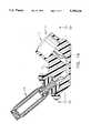
- FIGS. 1A-1Eshow several views of the complete hearing aid device constructed in accordance with the principles of the present invention
- FIG. 1Ais a cross-sectional elevation view of the entire device constructed in accordance with the principles of the present invention.
- FIG. 1Bis a top plan view of the hearing aid device of FIG. 1A;
- FIG. 1Cis an elevational view of the hearing aid device of FIG. 1A, showing the details of a disposable boot in cross-section, including its deformable material portion;
- FIG. 1Dis a partial cross-sectional view taken along line 1D-1D of FIG. 1A;
- FIG. 1Eis a bottom plan view of the hearing aid device of FIG. 1A, illustrating a loop antenna in the base;
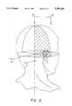
- FIG. 2is an oblique view of a human head, showing the anatomical sections designated as the coronal section, and the transverse section;
- FIG. 3Ashows the correct anatomical view of the transverse section of the human ear, taken along line 3--3 in FIG. 2;
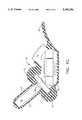
- FIG. 3Bshows the same view as FIG. 3A, however, it includes the placement of the hearing aid device
- FIG. 4Ashows the correct anatomical view of a coronal section of the human ear, taken along line 4--4 in FIG. 2;
- FIG. 4Bshows the same view as FIG. 4A, however, it also includes the placement of the hearing aid device
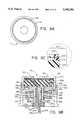
- FIGS. 5A-5Cshow the details of the speaker portion of the hearing aid device of FIG. 1A;
- FIG. 5Ais a plan view of the speaker portion of the hearing aid device of FIG. 1A, and a cross-sectional view of its articulated joint;
- FIG. 5Bis a longitudinal cross-section view of the speaker portion, taken along line 5B--5B of FIG. 5A;
- FIG. 5Cis a sectional view of the speaker portion, taken along line 5C--5C of FIG. 5B;
- FIGS. 6A-6Cshow the details of the outer cover of the hearing aid device of FIG. 5A;
- FIG. 6Ais a plan view of the speaker cover of FIG. 5A;
- FIG. 6Bis a cross-sectional elevation view of the speaker cover, taken along line 6B--6B of FIG. 6A;
- FIG. 6Cis a cross-sectional elevation view of the speaker cover, taken along line 6C--6C of FIG. 6A;
- FIGS. 7A-7Cshow the details of the armature of the hearing aid device of FIG. 5A;
- FIG. 7Ais a plan view of the speaker armature of FIG. 5A;
- FIG. 7Bis a cross-sectional elevation view of the armature, taken along line 7B--7B of FIG. 7A;
- FIG. 7Cis a cross-sectional elevation view of the armature, taken along line 7C--7C of FIG. 7A;
- FIGS. 8A-8Cshow details of the microphone using an electret device
- FIG. 8Ais a top plan view of a microphone used in the hearing aid device of FIG. 1A;
- FIG. 8Bis a cross-sectional elevation view of the microphone of FIG. 8A;
- FIG. 8Cis an enlargement of the upper right hand corner portion of FIG. 8B;
- FIGS. 9A-9Cshow an alternative microphone using a piezo electric device
- FIG. 9Ais a top plan view of an alternative microphone for the hearing aid device of FIG. 1A;
- FIG. 9Bis a cross-sectional elevation view of the microphone of FIG. 9A;
- FIG. 9Cis an enlargement of the upper right hand corner portion of FIG. 9B;
- FIG. 10shows an accelerometer, used in the hearing aid device of FIG. 1A;
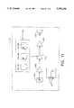
- FIG. 11is an electrical schematic of the hearing aid device of FIG. 1A having local controls.
- FIG. 12is an alternative electrical schematic of the hearing aid device of FIG. 1A, in this case, having a remote hand-held controller which communicates to the hearing aid device;
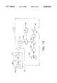
- FIG. 13is another alternative schematic for the hearing aid device of FIG. 1A which, in addition to what is described in FIG. 12, also has a accelerometer input;
- FIG. 14is another alternative electrical schematic that shows a signal processing unit which is remote to the hearing aid, and is in constant communication with the hearing aid device of FIG. 1A;
- FIG. 15is an electrical schematic which shows a remote hand-held device which communicates with the hearing aid device of FIG. 1, which in addition, contains a radio receiver.
- FIG. 1Bshows a preferred location for the electronic components of the device 10.
- An integrated circuit which makes up an accelerometeris illustrated shown as an electronic chip 50.
- An integrated circuit which contains the amplifiers and any transmitter and receiver componentsis illustrated as an electronic chip 52.
- a third electronic chip 51 for a third integrated circuitis disposed between chips 50 and 52, and can be used for additional transmitter components, as well as any desired supplemental signal processing circuitry. Electrical connections from the speaker and microphone portions 12 and 14 to the electronic components are preferably made at the connection of electronic chip 51.
- the hearing aid 10is covered with a disposal boot 20, which is made of an open cell deformable foam material which has a memory.
- the portion 21 of the disposable boot 20 which fits over the speaker portion 12is very thin, in the order of 1 mm, and is shown with an exaggerated thickness in FIG. 1C for purposes of illustration.
- One of the functions of the disposable boot 20is to seal the air inside the external auditory canal so that it cannot escape nor can any atmospheric air enter that area, once the hearing aid 10 is in place. This is accomplished by increasing the thickness of the boot 20 in the portion 22 surrounding the articulated joint 102.
- Another function of the disposable boot 20is to prevent contamination of the hearing aid by acting as a shield against eye wax, (cerumen) and other exfoliants of the epithelium of the ear canal.
- Another feature of the disposable boot 20is a pull-off tab 24 which allows the user to grip that portion of the disposable boot and pull the entire hearing aid out from the user's ear.
- the hearing aid device 10uses a power source, which in the preferred embodiment comprises two batteries 54.
- the batteries 54 of the preferred embodimentare of the type 377 and are not connected in series, but are instead used to provide a bipolar DC power source for the electronics of the hearing aid. It is obvious that other DC power sources could be used in lieu of the batteries 54.
- loop antenna 78A detail of the loop antenna 78 is illustrated in FIG. 1E. Such loop antenna 78 could be used for any radio frequency transmitter or receiver devices that might be used in conjunction with the hearing aid 10.
- FIG. 3Ais an anatomically accurate, transverse section of the human ear showing the important structural details relevant to the present invention.
- the curved surface of the concha 41is illustrated in the region bounded by the bracketed lines 40 in the illustration of FIG. 3A.
- the acoustic focus of the concha 41is located at the point identified by the numeral 36.
- the point 36is the location where the natural shape of the human ear focuses incoming sound waves.
- the external auditory canalis formed by two distinct portions.
- the outer most portion of the external auditory canalis the portion enumerated 30 between the two bracketed lines.
- the innermost portion of the external auditory canalis called the bony part of the external auditory canal 32, and lies between the innermost two bracketed lines 32.
- the tragus 38lies at the entrance to the externals auditory canal opposite the concha 41.
- the sigmoid portion of the cartilaginous part of the external auditory canalis the S-shaped dashed line identified by the numeral 42.
- the average inner diameter of the external auditory canalis approximately 7 mm.
- At the innermost portion of the external auditory canallies the tympanic membrane 34, which is also called the eardrum.
- the effective surface area of the tympanic membranelies in the range of 50-55 square mm.
- FIG. 4Ais a coronal section of the human ear, which is 90° from the transverse section of FIG. 3A.
- FIG. 3Bdepicts the hearing aid device 10 positioned in the human ear.
- the main body portion 16 of the hearing aid 10is located directly at the entrance of the external auditory canal.
- the main body position 16lies in contact with, and is hidden from view by the tragus 38.
- the microphone portion 14 of the hearing aid 10is advantageously located such that it is directly at the acoustic focus of the concha 36 so that it maximizes the natural sound gathering and direction locating anatomical features of the human ear.
- the speaker portion 12 of the hearing aidis located entirely inside the external auditory canal, and it fits past the sigmoid portion 42 of the cartilaginous part of the external auditory canal. Quite significantly, the speaker portion 12 is designed to fit entirely inside the external auditory canal, yet has a large enough surface area of active speaker element to effectively vibrate the human tympanic membrane 34.
- FIG. 4Bis a coronal section of the human ear.
- the microphone portion 14 of the hearing aidis located at the acoustic focus of the concha 36, and the speaker portion 12, which is clearly shown in this view, is located entirely inside the external auditory canal well past the sigmoid portion.
- the speaker portion 12 of the hearing aid device 10consists largely of a linear motor 100, which is described in detail in FIGS. 5A-5C.
- the top cover 112 of the linear motor 100consists of magnetically permeable material.
- the entire linear motor 100is held together and surrounded by an outer housing 140.
- the outer housing 140is made of shrinkable plastic material.
- the outer housing 140is pressed around the outer pole piece 132, which is also called a banjo housing.
- the outer pole piece 132is made of magnetically permeable material; in the preferred embodiment it is made of soft steel.
- the outer pole piece 132extends through the ball of the articulated joint 102, and is hollow in that region, acting as a conduit for the electrical conductors 118 that lead to the speaker coils 116 and 148.
- the articulated joint 102allows the speaker portion 12 to pivotally move in relation to the main body portion 16, which allows the speaker portion 12 to easily fit in the external auditory canal.
- the speaker membranes 114 and 150consist of a three micron polyester film having a surface area at least equal to the effective surface area of the tympanic membrane, i.e., approximately 64 square mm in the preferred embodiment.
- the elongated oval shape and construction of the top speaker membrane 114is also disclosed in FIGS. 7A-7C.
- the top coil 116is rigidly affixed to the top speaker membrane 114 at attachment edges 120.
- compliance enhancing ripples 124are formed in the top speaker membrane 114.
- An additional feature to make the speaker more effectiveis the curved pleats 122 in the material of the top speaker membrane.
- the top speaker coil 116consists of 15 turns of oval shaped windings, and is constructed of Number 48 AWG coated copper magnet wire.
- the coatingconsists of a polymeric insulation material and a secondary rubberized plastic shape-holding material.
- the top spacer ring 144holds the very outer edges of the top speaker membrane 114 in place, and consists of metallic material such as brass.
- the top armature of the linear motorincludes the top speaker membrane 114, the top coil 116, and the top spacer ring 144.
- the bottom speaker armatureconsists of the same types of components and materials as does the top speaker armature.
- the bottom armaturethere is a bottom speaker membrane 150, a bottom coil 148, and a bottom spacer ring 154.
- the materials of the bottom armatureare virtually the same as that of the top armature, however, certain features may be varied to achieve a tweeter-type speaker on the top (having enhanced treble response), for example, and a woofer-type speaker on the bottom (having enhanced bass response).
- Such features that could be variedare those that affect the mass, spring and damping characteristics of the armature, such as the thickness of the speaker membranes, the number of windings of the coil, and the size of the magnet wire which makes up the coil, and also the size and shape of the resonance cavities.
- the top speaker resonance cavityis identified by the numeral 126
- the bottom speakerhas a similar resonance cavity identified by numeral 156, which is larger in size (volume) for enhanced bass response in the illustrated embodiment.
- the control gap 130can be used to vary the amount of air that can be exchanged between two resonance cavities 126 and 156.
- the linear motor 100additionally consists of a permanent magnet 136, and a magnet support piece 134.
- the permanent magnet of the preferred embodimentconsists of Neodimium-Boron-Iron, or Samarium Cobalt. Neodimium-Boron-Iron can exert a stronger magnetic field than Samarium-Cobalt, however, Samarium-Cobalt will not rust.
- the attachment edges 120are node points for the attachment of the coils to the speaker membranes. This attachment is made by a rubber-based glue.
- the speaker of the preferred embodiment, as described above,is a moving coil circuit, whereas prior art small hearing aid speakers generally have used variable reluctance circuits, which generally have given poor low frequency performance.
- the microphone portion of the hearing aid 10is detailed in FIGS. 8A-8C and 9A-9C.
- the embodiment illustrated in FIGS. 8A-8Cuses an electret type microphone.
- Forming an outer housing for the microphoneis the microphone cover 160.
- This covercan be made of formed metal, such as aluminium, or formed plastic.
- a first spacer 162which consists of a material which is electrically nonconductive. This spacer is used to maintain a gap between the microphone cover 160 and the microphone diaphragm 164.
- the microphone diaphragmconsists of a permanently charged material, such as metallized film or metallized polyester.
- On the other side of the microphone diaphragm 164is a second spacer 166 which consists of a material which is electrically nonconductive. The second spacer 166 maintains the quiescent gap between the microphone diaphragm 164 and the plate 168.
- the plate 168consists of conductive metal such as nickel plated copper, or steel.
- the plate 168rests on top of the mounting block 172, and also is attached to the gate 176 of a field effect transistor 174.
- the mounting block 172is formed of electrically nonconductive material such as plastic.
- the mounting blockcontains a provision 170 for venting the gap which is inside the second spacer 166 and is between the microphone diagram 164 and the plate 168.
- the field effect transistor 174also has a source 178 and a drain 180, and with a pair of wires 182 attached, one to the gate and one to the source.
- Such electret microphone assemblies 184are available in the prior art, such as one made by Panasonic having a part number WM-6A.
- the microphone portion 14 illustrated in FIG. 8also consists of two potentiometers and the on/off switch.
- the on/off switchconsist of a conductive ring 190 which has a gap for the off portion of the ring.
- the turning of the microphone cover 160actuates this on/off switch.
- the treble-bass filter controlconsists of a first potentiometer.
- the first potentiometerhas a ring of resistance film media 194, which is not necessarily uniform, and a rotatable wiper 196.
- the first potentiometer media 194is physically located and held in place by a nonconductive support 198.
- the rotatable wiper 196is only engaged to rotate when the actuator 210 is depressed while being rotated.
- the actuator 210is forced down when the microphone cover 160 is depressed.
- the support structure 192is the overall housing base for maintaining the potentiometers in place while the microphone cover 160 is being depressed.
- a second potentiometercontrols the volume of the hearing aid.
- This second potentiometerconsist of a ring of resistance film media 202, a rotatable wiper 204, and physical support which consists of a nonconductive support 206.
- the second potentiometeroperates in the opposite sense as the first potentiometer in that its rotatable wiper 204 is actuated when the actuator 110 is not depressed.
- the spring 212keeps tension on the rotatable wiper 204, and allows it to be rotated.
- the potentiometers and the on/off controlmust have conducting means such as wires attached to them.
- a pair of wires 200runs to the first potentiometer
- a second pair of wires 208runs to the second potentiometer
- a third pair of wires 214runs to the on/off ring.
- a piezo type microphonecan alternatively be used rather than the electret type microphone.
- the microphone cover 220is approximately the same size as the electret microphone cover 160. In this case, the microphone cover 220 must be made out of a material which is electrically nonconductive.
- the first spacer 222Just beneath the microphone cover 220 is the first spacer 222. This first spacer consists of an electrically conductive material, and is connected by a wire to the positive input of the microphone transducer amplifier.
- the microphone diagram 224below (on the other side of) the first spacer 222 is the microphone diagram 224. This diagram consists of a material called Kynar, which is made by Pennwalt Corporation.
- a second spacer 226On the other side of the microphone diagram 224.
- This second spaceris also made of an electrically conductive material, and is connected to the negative input of the transistor amplifier.
- the two spacers 222 and 226 plus the microphone diagram 224rest on the mounting block 228, and have two wires 232 attached to the two spacers (one wire per spacer).
- the remaining parts of the microphone portion of the embodiment of FIG. 9Bare precisely the same as that shown in FIG. 8B.
- One embodiment of the hearing aidcan consist of an optional accelerometer assembly 248.
- the accelerometeris used to either enhance or attenuate the conductive sound of the user's voice through the user's bones into the cochlea of the ear. These conductive sound waves travel through the temporal bone which completely surrounds the inner ear, and directly excite the mechnoneural sensory structures within the inner ear. Conductive sound is present in the normal ear, and its magnitude is normally balanced with the air-borne portion of one's own voice. However, such conductive sound, if existing at a large magnitude, can be very distracting to the user, in which case the accelerometer signal would be attenuated.
- the accelerometer assembly 248is built on the integrated circuit 50 in the main body portion 16 of the device.
- the general layout of the accelerometeris given in FIGS. 10A-10B, which shows the substrate 240 and the seismic mass 242.
- the substratecan be made of silicon, as used in the substrate for integrated circuits.
- the seismic mass 242would consist of a high density material, such as copper.
- Sensing elements 244are laid out on the substrate 240 and consist of materials having electrical characteristics which are sensitive to strain.
- the nodes 246are enlarged pads so as to more easily make electrical connection to the accelerometer assembly 248.
- the entire accelerometer assembly 248is built onto the integrated circuit 50, and is physically isolated from the microphone and the speaker. The accelerometer is, therefore, not sensitive to air-borne sound waves, but only bone-conducted sound waves.
- the accelerometerneed not consist of a seismic mass 242 mounted on a strain gauged beam (substrate 240) as described above.
- Other types of accelerometers having similar size and constructioncould be used in the alternative.
- Such other types of accelerometerscould consist of a mass 242 mounted on the movable portion of a charged membrane 240, or a mass 242 mounted on a piezoelectric beam 240 (called a piezo bimorphic).
- the major difference between the different types of accelerometersis the material used for the beam (the substrate 240), the nature of the sensing elements 244 which are attached to the beam 240, and the signal conditioning electronics required among the various types.
- the electrical schematic in block diagram form of a stand alone hearing aid 10is given in FIG. 11.
- the control means 216consists of three control devices which are a part of the microphone portion 14.
- the three controls included in control means 216are the on/off switch, the volume control potentiometer, and the treble-bass filter potentiometer.
- FIG. 11uses an electret microphone 184, however, it should be recognized that any type of miniature microphone could be used in this application.
- the sound energyis transformed by the microphone 184 into electrical signals which are passed into the input microphone transducer amplifier 260. After initial amplification, the electrical signal is then passed into a set of amplifiers which act as a treble-bass filter and an intermediate gain amplifier 262.
- This treble-bass filter and intermediate gain amplifier 262communicates with the control means 216 so as to properly control the hearing aid as per the user's wishes. Any automatic gain control functions, whether linear or non-linear in profile, are performed by the intermediate gain amplifier 262.
- the output of the treble-bass filter and the intermediate gain amplifier 262is then communicated to an output power amplifier 264.
- the power amplifier 264has as its output stage a class B push-pull dual transistor output. By use of a dual DC voltage power supply (supplied by two DC batteries 54), all of the amplifiers in the hearing aid can run in a bipolar configuration, including the power amplifier.
- the above amplifiersincluding the output stage power amplifier, are all located on the integrated circuit 52.
- Some of the low-gain amplifier stagesuse an operational amplifier such as the OP-90, manufactured by Precision Monolithics.
- the OP-90is available on a semi-custom chip, or can be, of course, placed on a custom analog chip.
- a radio frequency transmitterwhich would require some type of antenna built into the hand-held unit, or an infrared transmitter, which would require an infrared light emitting diode, or possibly an ultrasonic transmitter means, which would require some type of high frequency speaker output.
- an infrared transmitterwhich would require an infrared light emitting diode, or possibly an ultrasonic transmitter means, which would require some type of high frequency speaker output.
- whichever means of communication is utilizedit is designated as 76 on FIG. 12.
- the communication means 76requires a corresponding receiver 74, which is in the hearing aid device 10.
- the receiver 74converts the communication signal to electrical signals, which are then passed to the control means 270.
- the control means 270is similar in function to the previously discussed control means 216 of FIG. 11, in that it controls the treble-base filter and intermediate gain amplifier 262 of the hearing aid 10.
- Also included as part of the control signalsis a local on/off control function 190.
- the local on/off control 190is needed to allow the user to completely turn off electrical power in the hearing aid device 10.
- the microphone 184receives sound energy and converts it to electrical energy, which is passed to the microphone transducer amplifier 260.
- the output of the transducer amplifier 260is communicated to the filter and gain amplifier 262, which is now controlled by control means 270, which utilizes the received information from the receiver 74.
- the electrical signalis then sent to the power amplifier 264, and finally to the speaker element 100.
- the receiver 74requires an antenna 78.
- FIG. 13Another embodiment of the hearing aid which uses a hand-held transmitter 70 is shown in FIG. 13.
- This embodimentalso includes an accelerometer 248, to either add or subtract conductive sound information.
- the hand-held transmitter 70consists of an operator interface 266, a controller 268, and a transmitter 72.
- the informationis communicated by means 76 to the receiver 74 of the hearing aid device 10. Once the information is received by the receiver 74, it is communicated to the control means 270 which also communicates with the local on/off control 190.
- the sound energy inputis received at the microphone 184, and is converted into an electrical signal which is first amplified by the microphone transducer amplifier 260, then modified and amplified by the filter and intermediate gain amplifier 262, and is finally sent to a new amplifier element 278 which is a summation amplifier.
- the mechanical vibrationsare sensed by the accelerometer 248, which converts the vibrations into an electrical signal.
- This electrical signalis received by the accelerometer transducer amplifier 272, which then outputs the signal to a gain amplifier stage 276.
- the control means 270also communicates information to a volume control 274. Volume control 274 controls the gain of amplifier 276, however, the control means 270 also passes a signal to gain amplifier 276 which makes it possible for it to have reverse polarity.
- Polaritywould be reversed in situations where the conductive sound picked up by the accelerometer 248 is to be attenuated.
- the output of the reversible polarity gain amplifier 276is then communicated to the summation amplifier 278. At this point the accelerometer signal is either subtracted or added to the microphone signal.
- the output of summation amplifier 278is then sent to the power amplifier 264 and then to the speaker element 100.
- FIG. 14there is a portable signal processing device 80, which can be either carried by hand or worn on the clothing (such as strapped to a belt) of the user.
- the userinputs information through the operator interface 280, which can be a key pad, which information is then communicated to a controller 282. That information is then communicated to the radio frequency transmitter 82. This information would be in the form of digital signals which are then transmitted via communication means 90 to the receiver 86 of the hearing aid 10.
- sound energyis picked up by the sound conversion means 185, which may be microphone 184, a vibration sensor, or the electrical summation of both and converted into electrical signals which are passed to the microphone transducer amplifier 260.
- the output of the transducer amplifier 260is sent to a second radio frequency transmitter 88.
- This informationis then communicated via communication means 90 to a second radio frequency receiver 84 which is located on the signal processing device 80.
- This informationis communicated from the output of the receiver 84 to a signal processing controller 284.
- the signal processor 284must work as nearly in real time as possible, to accept the audio information from the receiver 84 and then output the processed audio information in the form of an electrical signal to the radio frequency transmitter 82.
- communication means 90must be a full duplex means of communicating radio frequency information both to and from each device, the hearing aid 10 and the signal processing device 80.
- the control portion of the received signalis a digital series of commands 286. These commands are communicated to the control means 270 which also communicates to a local on/off control 190.
- the audio portion of the received information which is received by radio frequency receiver 86is an electrical signal 288. This audio signal is communicated to the filter and intermediate gain amplifier 262 which also communicates with the control means 270. The output of the filter and gain amplifier 262 is sent to the power amplifier 264 which outputs the signal to the speaker element 100.
- An alternative embodiment of the invention which employs signal processing techniquesis one that includes a self-contained enhanced signal processing controller within the hearing aid 10 itself. This embodiment is described in schematic form on FIG. 12, wherein the filter and intermediate gain amplifier 262 also contains the necessary signal processing controller to achieve the desired enhancement.
- FIG. 15Another embodiment of the invention can consist of a radio receiver 94 which can receive either commercial broadcast or local broadcast.
- this embodimentuses a hand-held transmitter 70, which consists of the elements of the operator interface 266, the controller 268, and the output transmitter 72. Information from the transmitter 72 is communicated by means 76 to a receiver 74 on the hearing aid device 10.
- the operator interface 266can also control the frequency to be received at the hearing aid device 10 receiver 94. That information is transmitted by transmitter 72 via communication means 76 to the receiver 74. This information is subsequently communicated to the control means 270 and then to the tuner 290.
- the control means 270also communicates with a local on/off control 190.
- Sound wave energyis received by the sound conversion means 185, which may be microphone 184, a vibration sensor, or the electrical summation of both and is converted to an electrical signal which is communicated to the microphone transducer amplifier 260.
- the output of this transducer amplifier 260is communicated to the filter and intermediate gain amplifier 262, whose output is then communicated to sound amplifier 278.
- the hearing aid device 10also receives radio frequency information via its receiver 94.
- Radio frequency receiver 94can receive commercial broadcasts, for example, in the AM and FM bands of commercial communications, from a commercial transmitter 92 via communication means 96.
- control means 270transfers information to the tuner 290 which then controls which radio station will be received by the radio frequency receiver 94.
- the output of the receiver 94is sent to a gain amplifier 276 whose gain is controlled by volume control 274 which communicates to the control means 270.
- the output of the gain amplifier 276is then sent to the summation amplifier 278 whose output consists of signals from both the microphone and the radio receiver.
- radio frequency receiver 94can receive a local broadcast which might consist of a miniature radio transmitter worn by the user which is broadcasting music, for example, from a compact disc player or from a cassette tape player. While such local radio transmitters may not be in use today, they are certainly foreseeable in the future, particularly after the present invention becomes common in the marketplace.
- the overall size, shape, and orientation of the hearing apparatusprovide a package which fits deeply into the external auditory canal such that its microphone is placed at the acoustic focus of the concha, and its speaker is placed between the sigmoid portion of the canal and the tympanic membrane. Such placement of the speaker, along with sealing the air inside the external auditory canal around the hearing apparatus, achieves a closely-coupled system.
- the hearing apparatuscan be used as a stand-alone device which includes all necessary signal-conditioning and amplification electronic circuitry, as well as enhanced signal processing, if so desired.
- the hearing apparatusalso can be used in conjunction with a separate hand-held transmitter for controlling various operational functions, a separate enhanced signal processing device, if desired, or used in communication with a radio transmitter.
Landscapes
- Engineering & Computer Science (AREA)
- Signal Processing (AREA)
- Acoustics & Sound (AREA)
- Physics & Mathematics (AREA)
- Neurosurgery (AREA)
- Otolaryngology (AREA)
- General Health & Medical Sciences (AREA)
- Health & Medical Sciences (AREA)
- Computer Networks & Wireless Communication (AREA)
- Manufacturing & Machinery (AREA)
- Headphones And Earphones (AREA)
- Prostheses (AREA)
- Circuit For Audible Band Transducer (AREA)
- Dental Preparations (AREA)
- Telephone Set Structure (AREA)
- Percussion Or Vibration Massage (AREA)
- Measurement And Recording Of Electrical Phenomena And Electrical Characteristics Of The Living Body (AREA)
Abstract
Description
Claims (61)
Priority Applications (3)
| Application Number | Priority Date | Filing Date | Title |
|---|---|---|---|
| US08/049,875US5390254A (en) | 1991-01-17 | 1993-04-19 | Hearing apparatus |
| US08/599,445US6041129A (en) | 1991-01-17 | 1996-01-18 | Hearing apparatus |
| US09/780,584US20010007050A1 (en) | 1991-01-17 | 2001-02-09 | Hearing apparatus |
Applications Claiming Priority (2)
| Application Number | Priority Date | Filing Date | Title |
|---|---|---|---|
| US64273591A | 1991-01-17 | 1991-01-17 | |
| US08/049,875US5390254A (en) | 1991-01-17 | 1993-04-19 | Hearing apparatus |
Related Parent Applications (1)
| Application Number | Title | Priority Date | Filing Date |
|---|---|---|---|
| US64273591AContinuation | 1991-01-17 | 1991-01-17 |
Related Child Applications (1)
| Application Number | Title | Priority Date | Filing Date |
|---|---|---|---|
| US30316194ADivision | 1991-01-17 | 1994-09-08 |
Publications (1)
| Publication Number | Publication Date |
|---|---|
| US5390254Atrue US5390254A (en) | 1995-02-14 |
Family
ID=24577785
Family Applications (3)
| Application Number | Title | Priority Date | Filing Date |
|---|---|---|---|
| US08/049,875Expired - Fee RelatedUS5390254A (en) | 1991-01-17 | 1993-04-19 | Hearing apparatus |
| US08/599,445Expired - LifetimeUS6041129A (en) | 1991-01-17 | 1996-01-18 | Hearing apparatus |
| US09/780,584AbandonedUS20010007050A1 (en) | 1991-01-17 | 2001-02-09 | Hearing apparatus |
Family Applications After (2)
| Application Number | Title | Priority Date | Filing Date |
|---|---|---|---|
| US08/599,445Expired - LifetimeUS6041129A (en) | 1991-01-17 | 1996-01-18 | Hearing apparatus |
| US09/780,584AbandonedUS20010007050A1 (en) | 1991-01-17 | 2001-02-09 | Hearing apparatus |
Country Status (10)
| Country | Link |
|---|---|
| US (3) | US5390254A (en) |
| EP (1) | EP0567535B1 (en) |
| JP (1) | JPH06506572A (en) |
| AT (1) | ATE247369T1 (en) |
| AU (1) | AU1189592A (en) |
| BR (1) | BR9205478A (en) |
| CA (1) | CA2100773A1 (en) |
| DE (1) | DE69233156T2 (en) |
| DK (1) | DK0567535T3 (en) |
| WO (1) | WO1992013430A1 (en) |
Cited By (94)
| Publication number | Priority date | Publication date | Assignee | Title |
|---|---|---|---|---|
| US5659620A (en)* | 1992-09-10 | 1997-08-19 | Kuhlman; Peer | Ear microphone for insertion in the ear in connection with portable telephone or radios |
| US5701348A (en)* | 1994-12-29 | 1997-12-23 | Decibel Instruments, Inc. | Articulated hearing device |
| US5721783A (en)* | 1995-06-07 | 1998-02-24 | Anderson; James C. | Hearing aid with wireless remote processor |
| US5764778A (en)* | 1995-06-07 | 1998-06-09 | Sensimetrics Corporation | Hearing aid headset having an array of microphones |
| US5909497A (en)* | 1996-10-10 | 1999-06-01 | Alexandrescu; Eugene | Programmable hearing aid instrument and programming method thereof |
| US5920635A (en)* | 1994-08-04 | 1999-07-06 | Lenz; Peter Joakim | Hearing aid |
| US5933506A (en)* | 1994-05-18 | 1999-08-03 | Nippon Telegraph And Telephone Corporation | Transmitter-receiver having ear-piece type acoustic transducing part |
| US5953435A (en)* | 1997-05-16 | 1999-09-14 | Hello Direct, Inc. | Intra-concha stabilizer with length adjustable conchal wall hook |
| US5956330A (en)* | 1997-03-31 | 1999-09-21 | Resound Corporation | Bandwidth management in a heterogenous wireless personal communications system |
| US6041129A (en)* | 1991-01-17 | 2000-03-21 | Adelman; Roger A. | Hearing apparatus |
| US6058197A (en)* | 1996-10-11 | 2000-05-02 | Etymotic Research | Multi-mode portable programming device for programmable auditory prostheses |
| US6112103A (en)* | 1996-12-03 | 2000-08-29 | Puthuff; Steven H. | Personal communication device |
| WO2000076271A1 (en)* | 1999-06-08 | 2000-12-14 | Insonus Medical, Inc. | Extended wear canal hearing device |
| US6175633B1 (en) | 1997-04-09 | 2001-01-16 | Cavcom, Inc. | Radio communications apparatus with attenuating ear pieces for high noise environments |
| US6212283B1 (en) | 1997-09-03 | 2001-04-03 | Decibel Instruments, Inc. | Articulation assembly for intracanal hearing devices |
| US20010028720A1 (en)* | 2000-02-17 | 2001-10-11 | Zezhang Hou | Null adaptation in multi-microphone directional system |
| US20020034310A1 (en)* | 2000-03-14 | 2002-03-21 | Audia Technology, Inc. | Adaptive microphone matching in multi-microphone directional system |
| US6366863B1 (en) | 1998-01-09 | 2002-04-02 | Micro Ear Technology Inc. | Portable hearing-related analysis system |
| US6387039B1 (en) | 2000-02-04 | 2002-05-14 | Ron L. Moses | Implantable hearing aid |
| US20020067838A1 (en)* | 2000-12-05 | 2002-06-06 | Starkey Laboratories, Inc. | Digital automatic gain control |
| USD468722S1 (en) | 2001-12-24 | 2003-01-14 | Hello Direct, Inc. | Headset with moveable earphones |
| US20030133578A1 (en)* | 2001-11-15 | 2003-07-17 | Durant Eric A. | Hearing aids and methods and apparatus for audio fitting thereof |
| WO2003067927A1 (en)* | 2002-02-06 | 2003-08-14 | Lichtblau G J | Hearing aid operative to cancel sounds propagating through the hearing aid case |
| US20030215106A1 (en)* | 2002-05-15 | 2003-11-20 | Lawrence Hagen | Diotic presentation of second-order gradient directional hearing aid signals |
| US20030215105A1 (en)* | 2002-05-16 | 2003-11-20 | Sacha Mike K. | Hearing aid with time-varying performance |
| US6718301B1 (en) | 1998-11-11 | 2004-04-06 | Starkey Laboratories, Inc. | System for measuring speech content in sound |
| US6775390B1 (en) | 2001-12-24 | 2004-08-10 | Hello Direct, Inc. | Headset with movable earphones |
| GB2401278A (en)* | 2003-04-30 | 2004-11-03 | Sennheiser Electronic | Improved pick-up of voice sounds |
| US20050008175A1 (en)* | 1997-01-13 | 2005-01-13 | Hagen Lawrence T. | Portable system for programming hearing aids |
| US6851048B2 (en) | 1997-01-13 | 2005-02-01 | Micro Ear Technology, Inc. | System for programming hearing aids |
| US6888948B2 (en) | 1997-01-13 | 2005-05-03 | Micro Ear Technology, Inc. | Portable system programming hearing aids |
| US20050157895A1 (en)* | 2004-01-16 | 2005-07-21 | Lichtblau George J. | Hearing aid having acoustical feedback protection |
| US6940988B1 (en) | 1998-11-25 | 2005-09-06 | Insound Medical, Inc. | Semi-permanent canal hearing device |
| US20050244024A1 (en)* | 2004-04-13 | 2005-11-03 | Thomas Fischer | Hearing aid with a resonator carried by the hearing aid housing |
| US20050283263A1 (en)* | 2000-01-20 | 2005-12-22 | Starkey Laboratories, Inc. | Hearing aid systems |
| US20060013420A1 (en)* | 2002-09-16 | 2006-01-19 | Sacha Michael K | Switching structures for hearing aid |
| US7010136B1 (en) | 1999-02-17 | 2006-03-07 | Micro Ear Technology, Inc. | Resonant response matching circuit for hearing aid |
| US20060050914A1 (en)* | 1998-11-25 | 2006-03-09 | Insound Medical, Inc. | Sealing retainer for extended wear hearing devices |
| US20060227990A1 (en)* | 2005-04-06 | 2006-10-12 | Knowles Electronics, Llc | Transducer Assembly and Method of Making Same |
| US20060227989A1 (en)* | 2005-03-28 | 2006-10-12 | Starkey Laboratories, Inc. | Antennas for hearing aids |
| US20060291682A1 (en)* | 1998-11-25 | 2006-12-28 | Insound Medical, Inc. | Sealing retainer for extended wear hearing devices |
| US20060291683A1 (en)* | 1998-11-25 | 2006-12-28 | Insound Medical, Inc. | Sealing retainer for extended wear hearing devices |
| US20070003087A1 (en)* | 2005-06-30 | 2007-01-04 | Insound Medical, Inc. | Hearing aid microphone protective barrier |
| US7162044B2 (en) | 1999-09-10 | 2007-01-09 | Starkey Laboratories, Inc. | Audio signal processing |
| US20070009130A1 (en)* | 2001-08-10 | 2007-01-11 | Clear-Tone Hearing Aid | BTE/CIC auditory device and modular connector system therefor |
| US20070064966A1 (en)* | 2001-08-10 | 2007-03-22 | Hear-Wear Technologies, Llc | BTE/CIC auditory device and modular connector system therefor |
| US20080008341A1 (en)* | 2006-07-10 | 2008-01-10 | Starkey Laboratories, Inc. | Method and apparatus for a binaural hearing assistance system using monaural audio signals |
| US20080056520A1 (en)* | 2004-02-19 | 2008-03-06 | Oticon A/S | Hearing Aid with Antenna for Reception and Transmission of Electromagnetic Signals |
| US20080069386A1 (en)* | 1999-06-08 | 2008-03-20 | Insound Medical, Inc. | Precision micro-hole for extended life batteries |
| US20080107287A1 (en)* | 2006-11-06 | 2008-05-08 | Terry Beard | Personal hearing control system and method |
| US20080159548A1 (en)* | 2007-01-03 | 2008-07-03 | Starkey Laboratories, Inc. | Wireless system for hearing communication devices providing wireless stereo reception modes |
| US20090074220A1 (en)* | 2007-08-14 | 2009-03-19 | Insound Medical, Inc. | Combined microphone and receiver assembly for extended wear canal hearing devices |
| US20090097683A1 (en)* | 2007-09-18 | 2009-04-16 | Starkey Laboratories, Inc. | Method and apparatus for a hearing assistance device using mems sensors |
| US20100040248A1 (en)* | 2008-08-13 | 2010-02-18 | Intelligent Systems Incorporated | Hearing Assistance Using an External Coprocessor |
| US20100142739A1 (en)* | 2008-12-04 | 2010-06-10 | Schindler Robert A | Insertion Device for Deep-in-the-Canal Hearing Devices |
| US20100158295A1 (en)* | 2008-12-19 | 2010-06-24 | Starkey Laboratories, Inc. | Antennas for custom fit hearing assistance devices |
| US20100158293A1 (en)* | 2008-12-19 | 2010-06-24 | Starkey Laboratories, Inc. | Parallel antennas for standard fit hearing assistance devices |
| US20100172529A1 (en)* | 2008-12-31 | 2010-07-08 | Starkey Laboratories, Inc. | Method and apparatus for detecting user activities from within a hearing assistance device using a vibration sensor |
| WO2010104950A1 (en)* | 2009-03-11 | 2010-09-16 | Stavros Basseas | On-site, custom fitted hearing equalizer |
| US20100322452A1 (en)* | 2004-02-05 | 2010-12-23 | Insound Medical, Inc. | Contamination resistant ports for hearing devices |
| US20110055120A1 (en)* | 2009-08-31 | 2011-03-03 | Starkey Laboratories, Inc. | Genetic algorithms with robust rank estimation for hearing assistance devices |
| US20110103605A1 (en)* | 2009-10-30 | 2011-05-05 | Etymotic Research, Inc. | Electronic earplug |
| WO2011055367A1 (en) | 2009-11-08 | 2011-05-12 | Objet Geometries Ltd. | Hearing aid and method of fabricating the same |
| US20110200213A1 (en)* | 2010-02-12 | 2011-08-18 | Audiotoniq, Inc. | Hearing aid with an accelerometer-based user input |
| US8300862B2 (en) | 2006-09-18 | 2012-10-30 | Starkey Kaboratories, Inc | Wireless interface for programming hearing assistance devices |
| US8538061B2 (en) | 2010-07-09 | 2013-09-17 | Shure Acquisition Holdings, Inc. | Earphone driver and method of manufacture |
| US8548186B2 (en) | 2010-07-09 | 2013-10-01 | Shure Acquisition Holdings, Inc. | Earphone assembly |
| US8549733B2 (en) | 2010-07-09 | 2013-10-08 | Shure Acquisition Holdings, Inc. | Method of forming a transducer assembly |
| US8565457B2 (en) | 2008-12-19 | 2013-10-22 | Starkey Laboratories, Inc. | Antennas for standard fit hearing assistance devices |
| US20140023217A1 (en)* | 2012-07-23 | 2014-01-23 | Starkey Laboratories, Inc. | Methods and apparatus for improving speech understanding in a large crowd |
| US20140072146A1 (en)* | 2012-09-13 | 2014-03-13 | DSP Group | Optical microphone and method for detecting body conducted sound signals |
| US8682016B2 (en) | 2011-11-23 | 2014-03-25 | Insound Medical, Inc. | Canal hearing devices and batteries for use with same |
| US8718288B2 (en) | 2007-12-14 | 2014-05-06 | Starkey Laboratories, Inc. | System for customizing hearing assistance devices |
| US8737658B2 (en) | 2008-12-19 | 2014-05-27 | Starkey Laboratories, Inc. | Three dimensional substrate for hearing assistance devices |
| US8737653B2 (en) | 2009-12-30 | 2014-05-27 | Starkey Laboratories, Inc. | Noise reduction system for hearing assistance devices |
| US8761423B2 (en) | 2011-11-23 | 2014-06-24 | Insound Medical, Inc. | Canal hearing devices and batteries for use with same |
| US20140221729A1 (en)* | 2008-01-21 | 2014-08-07 | David L. Basinger | Automatic gain control for implanted microphone |
| US8808906B2 (en) | 2011-11-23 | 2014-08-19 | Insound Medical, Inc. | Canal hearing devices and batteries for use with same |
| US20150043762A1 (en)* | 2013-08-09 | 2015-02-12 | Samsung Electronics Co., Ltd. | Hearing device and method of low power operation thereof |
| US8965016B1 (en) | 2013-08-02 | 2015-02-24 | Starkey Laboratories, Inc. | Automatic hearing aid adaptation over time via mobile application |
| US8971559B2 (en) | 2002-09-16 | 2015-03-03 | Starkey Laboratories, Inc. | Switching structures for hearing aid |
| US9473859B2 (en) | 2008-12-31 | 2016-10-18 | Starkey Laboratories, Inc. | Systems and methods of telecommunication for bilateral hearing instruments |
| US9604325B2 (en) | 2011-11-23 | 2017-03-28 | Phonak, LLC | Canal hearing devices and batteries for use with same |
| US9774961B2 (en) | 2005-06-05 | 2017-09-26 | Starkey Laboratories, Inc. | Hearing assistance device ear-to-ear communication using an intermediate device |
| US9838808B2 (en)* | 2005-12-12 | 2017-12-05 | Exsilent Research B.V. | Hearing aid |
| US20180084351A1 (en)* | 2016-09-21 | 2018-03-22 | Starkey Laboratories, Inc. | Radio frequency antenna for an in-the-ear hearing device |
| US10003379B2 (en) | 2014-05-06 | 2018-06-19 | Starkey Laboratories, Inc. | Wireless communication with probing bandwidth |
| US20180190261A1 (en)* | 2015-06-25 | 2018-07-05 | Boe Technology Group Co., Ltd. | Voice synthesis device, voice synthesis method, bone conduction helmet and hearing aid |
| US10142747B2 (en) | 2008-12-19 | 2018-11-27 | Starkey Laboratories, Inc. | Three dimensional substrate for hearing assistance devices |
| US10629969B2 (en) | 2014-07-27 | 2020-04-21 | Sonova Ag | Batteries and battery manufacturing methods |
| US11134352B2 (en) | 2020-01-29 | 2021-09-28 | Sonova Ag | Hearing device with wax guard interface |
| US11638108B2 (en) | 2020-11-27 | 2023-04-25 | Sonova Ag | Canal hearing devices with sound port contaminant guards |
| US12183341B2 (en) | 2008-09-22 | 2024-12-31 | St Casestech, Llc | Personalized sound management and method |
| US12249326B2 (en) | 2007-04-13 | 2025-03-11 | St Case1Tech, Llc | Method and device for voice operated control |
Families Citing this family (62)
| Publication number | Priority date | Publication date | Assignee | Title |
|---|---|---|---|---|
| US5606621A (en)* | 1995-06-14 | 1997-02-25 | Siemens Hearing Instruments, Inc. | Hybrid behind-the-ear and completely-in-canal hearing aid |
| US7010137B1 (en)* | 1997-03-12 | 2006-03-07 | Sarnoff Corporation | Hearing aid |
| US6205227B1 (en) | 1998-01-31 | 2001-03-20 | Sarnoff Corporation | Peritympanic hearing instrument |
| AUPP927599A0 (en)* | 1999-03-17 | 1999-04-15 | Curtin University Of Technology | Tinnitus rehabilitation device and method |
| US7520851B2 (en)* | 1999-03-17 | 2009-04-21 | Neurominics Pty Limited | Tinnitus rehabilitation device and method |
| US7130437B2 (en)* | 2000-06-29 | 2006-10-31 | Beltone Electronics Corporation | Compressible hearing aid |
| US6643378B2 (en) | 2001-03-02 | 2003-11-04 | Daniel R. Schumaier | Bone conduction hearing aid |
| EP1283657A1 (en)* | 2001-08-07 | 2003-02-12 | Phonic Ear Incorporated | Communication device incorporating embedded frequency selective device |
| US6664713B2 (en)* | 2001-12-04 | 2003-12-16 | Peter V. Boesen | Single chip device for voice communications |
| US7751580B2 (en) | 2002-09-10 | 2010-07-06 | Auditory Licensing Company, Llc | Open ear hearing aid system |
| US7421086B2 (en) | 2002-09-10 | 2008-09-02 | Vivatone Hearing Systems, Llc | Hearing aid system |
| NZ539237A (en)* | 2002-10-09 | 2006-11-30 | Univ East Carolina | Frequency altered feedback for treating non-stuttering pathologies |
| DE10304479B3 (en)* | 2003-02-04 | 2004-07-22 | Siemens Audiologische Technik Gmbh | Data transmission and reception device for remote control of hearing aid with transmission and reception coils wound around common core |
| DE10344032A1 (en)* | 2003-09-23 | 2005-06-23 | Schlegel, Udo D. | Hearing system suitable for people with hearing loss |
| US20050091060A1 (en)* | 2003-10-23 | 2005-04-28 | Wing Thomas W. | Hearing aid for increasing voice recognition through voice frequency downshift and/or voice substitution |
| US7668325B2 (en) | 2005-05-03 | 2010-02-23 | Earlens Corporation | Hearing system having an open chamber for housing components and reducing the occlusion effect |
| US8401212B2 (en) | 2007-10-12 | 2013-03-19 | Earlens Corporation | Multifunction system and method for integrated hearing and communication with noise cancellation and feedback management |
| US7302071B2 (en)* | 2004-09-15 | 2007-11-27 | Schumaier Daniel R | Bone conduction hearing assistance device |
| JP2006256843A (en)* | 2005-03-18 | 2006-09-28 | Toshiba Elevator Co Ltd | Voice broadcast system of elevator |
| WO2006101425A1 (en)* | 2005-03-23 | 2006-09-28 | Peter Stevrin | Ear shell with communication chip |
| DE102005032274B4 (en)* | 2005-07-11 | 2007-05-10 | Siemens Audiologische Technik Gmbh | Hearing apparatus and corresponding method for eigenvoice detection |
| US20120033823A1 (en)* | 2006-01-10 | 2012-02-09 | President And Fellows Of Harvard College | Nano-otologic protective equipment for impact noise toxicity and/or blast overpressure exposure |
| US8100922B2 (en)* | 2007-04-27 | 2012-01-24 | Ethicon Endo-Surgery, Inc. | Curved needle suturing tool |
| EP2206362B1 (en) | 2007-10-16 | 2014-01-08 | Phonak AG | Method and system for wireless hearing assistance |
| WO2009049645A1 (en) | 2007-10-16 | 2009-04-23 | Phonak Ag | Method and system for wireless hearing assistance |
| EP2296750B1 (en)* | 2008-06-13 | 2015-12-16 | Cochlear Americas | Implantable sound sensor for hearing prostheses |
| WO2009155358A1 (en) | 2008-06-17 | 2009-12-23 | Earlens Corporation | Optical electro-mechanical hearing devices with separate power and signal components |
| BRPI0919266A2 (en) | 2008-09-22 | 2017-05-30 | SoundBeam LLC | device and method for transmitting an audio signal to a user, methods for manufacturing a device for transmitting an audio signal to the user, and for providing an audio device for a user, and device and method for transmitting a sound for a user. user having a tympanic membrane |
| DK2190216T3 (en)* | 2008-11-20 | 2011-11-14 | Oticon As | Binaural hearing instrument |
| JP4809912B2 (en)* | 2009-07-03 | 2011-11-09 | ホシデン株式会社 | Condenser microphone |
| DK2393309T3 (en)* | 2010-06-07 | 2020-01-20 | Oticon Medical As | Apparatus and method for applying a vibration signal to a human skull bone |
| EP2580922B1 (en) | 2010-06-14 | 2019-03-20 | Turtle Beach Corporation | Improved parametric signal processing and emitter systems and related methods |
| CA2807808A1 (en)* | 2010-08-09 | 2012-02-16 | #3248362 Nova Scotia Limited | Personal listening device |
| US8693719B2 (en) | 2010-10-08 | 2014-04-08 | Starkey Laboratories, Inc. | Adjustment and cleaning tool for a hearing assistance device |
| EP2656639B1 (en) | 2010-12-20 | 2020-05-13 | Earlens Corporation | Anatomically customized ear canal hearing apparatus |
| US9179228B2 (en)* | 2011-12-09 | 2015-11-03 | Sophono, Inc. | Systems devices, components and methods for providing acoustic isolation between microphones and transducers in bone conduction magnetic hearing aids |
| US9036831B2 (en) | 2012-01-10 | 2015-05-19 | Turtle Beach Corporation | Amplification system, carrier tracking systems and related methods for use in parametric sound systems |
| US8958580B2 (en) | 2012-04-18 | 2015-02-17 | Turtle Beach Corporation | Parametric transducers and related methods |
| US8934650B1 (en) | 2012-07-03 | 2015-01-13 | Turtle Beach Corporation | Low profile parametric transducers and related methods |
| US10008125B2 (en) | 2013-01-03 | 2018-06-26 | East Carolina University | Methods, systems, and devices for multi-user treatment for improvement of reading comprehension using frequency altered feedback |
| US8903104B2 (en) | 2013-04-16 | 2014-12-02 | Turtle Beach Corporation | Video gaming system with ultrasonic speakers |
| EP3005731B2 (en) | 2013-06-03 | 2020-07-15 | Sonova AG | Method for operating a hearing device and a hearing device |
| US9332344B2 (en) | 2013-06-13 | 2016-05-03 | Turtle Beach Corporation | Self-bias emitter circuit |
| US8988911B2 (en) | 2013-06-13 | 2015-03-24 | Turtle Beach Corporation | Self-bias emitter circuit |
| US10034103B2 (en) | 2014-03-18 | 2018-07-24 | Earlens Corporation | High fidelity and reduced feedback contact hearing apparatus and methods |
| DK3169396T3 (en) | 2014-07-14 | 2021-06-28 | Earlens Corp | Sliding bias and peak limitation for optical hearing aids |
| WO2016078711A1 (en) | 2014-11-20 | 2016-05-26 | Widex A/S | Secure connection between internet server and hearing aid |
| KR20170088916A (en) | 2014-11-20 | 2017-08-02 | 와이덱스 에이/에스 | Hearing aid user account management |
| US9924276B2 (en) | 2014-11-26 | 2018-03-20 | Earlens Corporation | Adjustable venting for hearing instruments |
| KR101626865B1 (en)* | 2015-03-11 | 2016-06-03 | 주식회사 이엠텍 | Microspeaker with improved attaching sturucture of voice coil |
| DK3888564T3 (en) | 2015-10-02 | 2025-07-14 | Earlens Corp | DEVICE FOR CUSTOMIZED DELIVERY OF MEDICINE IN THE EAR CANAL |
| US11350226B2 (en) | 2015-12-30 | 2022-05-31 | Earlens Corporation | Charging protocol for rechargeable hearing systems |
| US10492010B2 (en) | 2015-12-30 | 2019-11-26 | Earlens Corporations | Damping in contact hearing systems |
| US10178483B2 (en) | 2015-12-30 | 2019-01-08 | Earlens Corporation | Light based hearing systems, apparatus, and methods |
| EP3510796A4 (en) | 2016-09-09 | 2020-04-29 | Earlens Corporation | Contact hearing systems, apparatus and methods |
| WO2018093733A1 (en) | 2016-11-15 | 2018-05-24 | Earlens Corporation | Improved impression procedure |
| US10821027B2 (en) | 2017-02-08 | 2020-11-03 | Intermountain Intellectual Asset Management, Llc | Devices for filtering sound and related methods |
| WO2019173470A1 (en) | 2018-03-07 | 2019-09-12 | Earlens Corporation | Contact hearing device and retention structure materials |
| WO2019199680A1 (en) | 2018-04-09 | 2019-10-17 | Earlens Corporation | Dynamic filter |
| US10492011B1 (en) | 2019-02-19 | 2019-11-26 | Joel E. Haynes | Non-surgical bone conduction hearing aid |
| WO2022154238A1 (en)* | 2021-01-12 | 2022-07-21 | 삼성전자 주식회사 | Microphone module and electronic device comprising microphone module |
| CN115334436B (en)* | 2022-08-11 | 2024-06-04 | 厦门瑞听听力科技有限公司 | Anti-lost hearing aid with positioning function |
Citations (72)
| Publication number | Priority date | Publication date | Assignee | Title |
|---|---|---|---|---|
| US1029355A (en)* | 1912-01-25 | 1912-06-11 | William J Francke | Flexible coupling. |
| US1582473A (en)* | 1924-05-24 | 1926-04-27 | Cliftophone Ltd | Sound-recording and sound-reproducing instrument |
| US1630028A (en)* | 1925-01-15 | 1927-05-24 | De Elbert A Reynolds | Ear phone |
| US1699786A (en)* | 1927-08-06 | 1929-01-22 | Westinghouse Electric & Mfg Co | Pressure-distributing device |
| US1732351A (en)* | 1926-03-31 | 1929-10-22 | George F Borkman | Balanced resiliency multiple-action one-piece diaphragm |
| US1738853A (en)* | 1927-06-29 | 1929-12-10 | Arthur S Thayer | Diaphragm for transmitters and receivers |
| US1984439A (en)* | 1928-10-10 | 1934-12-18 | Rca Corp | Diaphragm |
| US2069242A (en)* | 1933-01-19 | 1937-02-02 | George A Graham | Electroacoustic energy converting system |
| US2439665A (en)* | 1944-01-31 | 1948-04-13 | Rca Corp | Sound reproducing device |
| US2442791A (en)* | 1945-09-07 | 1948-06-08 | Bell Telephone Labor Inc | Acoustic device |
| US3013905A (en)* | 1958-03-07 | 1961-12-19 | Gamzon Robert Ruben | Electroacoustic transducers |
| US3066200A (en)* | 1958-08-11 | 1962-11-27 | William Ward Jackson | Speaker device |
| US3141071A (en)* | 1960-07-18 | 1964-07-14 | Rosen Alfred H | Full range electroacoustic transducers |
| US3170046A (en)* | 1961-12-05 | 1965-02-16 | Earmaster Inc | Hearing aid |
| US3346704A (en)* | 1963-12-27 | 1967-10-10 | Jack L Mahoney | Means for aiding hearing |
| US3366748A (en)* | 1964-09-22 | 1968-01-30 | Artnell Company | Loudspeaker diaphragm and driver |
| US3423543A (en)* | 1965-06-24 | 1969-01-21 | Harry W Kompanek | Loudspeaker with piezoelectric wafer driving elements |
| US3527901A (en)* | 1967-03-28 | 1970-09-08 | Dahlberg Electronics | Hearing aid having resilient housing |
| US3557775A (en)* | 1963-12-27 | 1971-01-26 | Jack Lawrence Mahoney | Method of implanting a hearing aid |
| US3563337A (en)* | 1968-03-06 | 1971-02-16 | Hitachi Ltd | Electroacoustic transducer |
| US3712962A (en)* | 1971-04-05 | 1973-01-23 | J Epley | Implantable piezoelectric hearing aid |
| US3746789A (en)* | 1971-10-20 | 1973-07-17 | E Alcivar | Tissue conduction microphone utilized to activate a voice operated switch |
| US3764748A (en)* | 1972-05-19 | 1973-10-09 | J Branch | Implanted hearing aids |
| US3852540A (en)* | 1971-12-30 | 1974-12-03 | Elektroakustik Ag F | In ear hearing apparatus |
| US3870832A (en)* | 1972-07-18 | 1975-03-11 | John M Fredrickson | Implantable electromagnetic hearing aid |
| US3873784A (en)* | 1973-03-29 | 1975-03-25 | Audio Arts Inc | Acoustic transducer |
| US3882285A (en)* | 1973-10-09 | 1975-05-06 | Vicon Instr Company | Implantable hearing aid and method of improving hearing |
| US3890474A (en)* | 1972-05-17 | 1975-06-17 | Raymond C Glicksberg | Sound amplitude limiters |
| US3919499A (en)* | 1974-01-11 | 1975-11-11 | Magnepan Inc | Planar speaker |
| US3983337A (en)* | 1973-06-21 | 1976-09-28 | Babbco, Ltd. | Broad-band acoustic speaker |
| US4068090A (en)* | 1975-07-01 | 1978-01-10 | Kabushiki Kaisha Suwa Seikosha | Hearing aid |
| US4150262A (en)* | 1974-11-18 | 1979-04-17 | Hiroshi Ono | Piezoelectric bone conductive in ear voice sounds transmitting and receiving apparatus |
| US4210786A (en)* | 1979-01-24 | 1980-07-01 | Magnepan, Incorporated | Magnetic field structure for planar speaker |
| US4228327A (en)* | 1978-02-25 | 1980-10-14 | Tadashi Sawafuji | Electromagnetic type acoustic transducers |
| US4276452A (en)* | 1978-08-15 | 1981-06-30 | Sony Corporation | Membrane type electro-acoustic transducer |
| US4284856A (en)* | 1979-09-24 | 1981-08-18 | Hochmair Ingeborg | Multi-frequency system and method for enhancing auditory stimulation and the like |
| US4324312A (en)* | 1978-11-14 | 1982-04-13 | James B. Lansing Sound, Inc. | Diaphragm suspension construction |
| US4329676A (en)* | 1980-01-10 | 1982-05-11 | Resistance Technology, Inc. | Potentiometer |
| US4334315A (en)* | 1979-05-04 | 1982-06-08 | Gen Engineering, Ltd. | Wireless transmitting and receiving systems including ear microphones |
| US4357497A (en)* | 1979-09-24 | 1982-11-02 | Hochmair Ingeborg | System for enhancing auditory stimulation and the like |
| US4433214A (en)* | 1981-12-24 | 1984-02-21 | Motorola, Inc. | Acoustical transducer with a slotted piston suspension |
| US4471172A (en)* | 1982-03-01 | 1984-09-11 | Magnepan, Inc. | Planar diaphragm transducer with improved magnetic circuit |
| US4471490A (en)* | 1983-02-16 | 1984-09-11 | Gaspare Bellafiore | Hearing aid |
| US4480155A (en)* | 1982-03-01 | 1984-10-30 | Magnepan, Inc. | Diaphragm type magnetic transducer |
| US4520236A (en)* | 1983-11-30 | 1985-05-28 | Nu-Bar Electronics | Sound transfer from a hearing aid to the human ear drum |
| US4539440A (en)* | 1983-05-16 | 1985-09-03 | Michael Sciarra | In-canal hearing aid |
| US4622692A (en)* | 1983-10-12 | 1986-11-11 | Linear Technology Inc. | Noise reduction system |
| US4637402A (en)* | 1980-04-28 | 1987-01-20 | Adelman Roger A | Method for quantitatively measuring a hearing defect |
| US4653103A (en)* | 1985-02-08 | 1987-03-24 | Hitachi, Ltd. | Loudspeaker structure and system |
| US4703540A (en)* | 1985-06-28 | 1987-11-03 | Davis Ronald P | Window stay |
| US4706778A (en)* | 1985-11-15 | 1987-11-17 | Topholm & Westermann Aps | In-the-ear-canal hearing aid |
| US4718096A (en)* | 1983-05-18 | 1988-01-05 | Speech Systems, Inc. | Speech recognition system |
| US4723296A (en)* | 1985-04-23 | 1988-02-02 | U.S. Philips Corporation | Electrodynamic transducer of the isophase or ribbon type |
| US4735759A (en)* | 1985-02-04 | 1988-04-05 | Gaspare Bellafiore | Method of making a hearing aid |
| US4759070A (en)* | 1986-05-27 | 1988-07-19 | Voroba Technologies Associates | Patient controlled master hearing aid |
| US4802228A (en)* | 1986-10-24 | 1989-01-31 | Bernard Silverstein | Amplifier filter system for speech therapy |
| US4800982A (en)* | 1987-10-14 | 1989-01-31 | Industrial Research Products, Inc. | Cleanable in-the-ear electroacoustic transducer |
| US4817609A (en)* | 1987-09-11 | 1989-04-04 | Resound Corporation | Method for treating hearing deficiencies |
| US4829581A (en)* | 1985-06-07 | 1989-05-09 | U.S. Philips Corp. | Electrodynamic transducer comprising a two-part diaphragm |
| US4845757A (en)* | 1987-02-17 | 1989-07-04 | Siemens Aktiengesellschaft | Circuit for recognizing oscillations in a useful signal due to feedback between acoustic input and output transducers |
| US4845755A (en)* | 1984-08-28 | 1989-07-04 | Siemens Aktiengesellschaft | Remote control hearing aid |
| US4868517A (en)* | 1988-02-23 | 1989-09-19 | Resound Corporation | Variolosser |
| US4870688A (en)* | 1986-05-27 | 1989-09-26 | Barry Voroba | Mass production auditory canal hearing aid |
| US4880076A (en)* | 1986-12-05 | 1989-11-14 | Minnesota Mining And Manufacturing Company | Hearing aid ear piece having disposable compressible polymeric foam sleeve |
| US4882762A (en)* | 1988-02-23 | 1989-11-21 | Resound Corporation | Multi-band programmable compression system |
| US4882761A (en)* | 1988-02-23 | 1989-11-21 | Resound Corporation | Low voltage programmable compressor |
| US4901354A (en)* | 1987-12-18 | 1990-02-13 | Daimler-Benz Ag | Method for improving the reliability of voice controls of function elements and device for carrying out this method |
| US4920570A (en)* | 1987-12-18 | 1990-04-24 | West Henry L | Modular assistive listening system |
| US4937876A (en)* | 1988-09-26 | 1990-06-26 | U.S. Philips Corporation | In-the-ear hearing aid |
| US4947432A (en)* | 1986-02-03 | 1990-08-07 | Topholm & Westermann Aps | Programmable hearing aid |
| US4962537A (en)* | 1987-09-25 | 1990-10-09 | Siemens Aktiengesellschaft | Shape adaptable in-the-ear hearing aid |
| US5125032A (en)* | 1988-12-02 | 1992-06-23 | Erwin Meister | Talk/listen headset |
Family Cites Families (12)
| Publication number | Priority date | Publication date | Assignee | Title |
|---|---|---|---|---|
| US26258A (en)* | 1859-11-29 | Button | ||
| NL34823C (en)* | 1930-07-29 | |||
| US2848560A (en)* | 1954-09-20 | 1958-08-19 | Beltone Hearing Aid Company | Hearing aid receiver |
| US2964596A (en)* | 1956-08-01 | 1960-12-13 | Zenith Radio Corp | Sound-reproducing device |
| USRE26258E (en) | 1964-04-02 | 1967-08-29 | In-the-ear hearing aid | |
| US3389232A (en)* | 1965-07-15 | 1968-06-18 | Beltone Electronics Corp | Hearing aid and ear mold assembly |
| US3414685A (en)* | 1965-09-23 | 1968-12-03 | Dahlberg Electronics | In-the-ear hearing aid |
| JPS5250646B2 (en)* | 1972-10-16 | 1977-12-26 | ||
| US4291203A (en)* | 1979-09-11 | 1981-09-22 | Gaspare Bellafiore | Hearing aid device |
| US4703510A (en)* | 1982-06-17 | 1987-10-27 | Larson David A | Electro-acoustic transducer with diaphragm and blank therefor |
| AU7659491A (en)* | 1990-03-30 | 1991-10-30 | Thomas M. Lott | Assistive listening device |
| CA2100773A1 (en)* | 1991-01-17 | 1992-07-18 | Roger A. Adelman | Hearing apparatus |
- 1992
- 1992-01-16CACA002100773Apatent/CA2100773A1/ennot_activeAbandoned
- 1992-01-16BRBR9205478Apatent/BR9205478A/ennot_activeIP Right Cessation
- 1992-01-16DKDK92903788Tpatent/DK0567535T3/enactive
- 1992-01-16ATAT92903788Tpatent/ATE247369T1/ennot_activeIP Right Cessation
- 1992-01-16JPJP4504587Apatent/JPH06506572A/enactivePending
- 1992-01-16AUAU11895/92Apatent/AU1189592A/ennot_activeAbandoned
- 1992-01-16DEDE69233156Tpatent/DE69233156T2/ennot_activeExpired - Lifetime
- 1992-01-16WOPCT/US1992/000380patent/WO1992013430A1/enactiveIP Right Grant
- 1992-01-16EPEP92903788Apatent/EP0567535B1/ennot_activeExpired - Lifetime
- 1993
- 1993-04-19USUS08/049,875patent/US5390254A/ennot_activeExpired - Fee Related
- 1996
- 1996-01-18USUS08/599,445patent/US6041129A/ennot_activeExpired - Lifetime
- 2001
- 2001-02-09USUS09/780,584patent/US20010007050A1/ennot_activeAbandoned
Patent Citations (73)
| Publication number | Priority date | Publication date | Assignee | Title |
|---|---|---|---|---|
| US1029355A (en)* | 1912-01-25 | 1912-06-11 | William J Francke | Flexible coupling. |
| US1582473A (en)* | 1924-05-24 | 1926-04-27 | Cliftophone Ltd | Sound-recording and sound-reproducing instrument |
| US1630028A (en)* | 1925-01-15 | 1927-05-24 | De Elbert A Reynolds | Ear phone |
| US1732351A (en)* | 1926-03-31 | 1929-10-22 | George F Borkman | Balanced resiliency multiple-action one-piece diaphragm |
| US1738853A (en)* | 1927-06-29 | 1929-12-10 | Arthur S Thayer | Diaphragm for transmitters and receivers |
| US1699786A (en)* | 1927-08-06 | 1929-01-22 | Westinghouse Electric & Mfg Co | Pressure-distributing device |
| US1984439A (en)* | 1928-10-10 | 1934-12-18 | Rca Corp | Diaphragm |
| US2069242A (en)* | 1933-01-19 | 1937-02-02 | George A Graham | Electroacoustic energy converting system |
| US2439665A (en)* | 1944-01-31 | 1948-04-13 | Rca Corp | Sound reproducing device |
| US2442791A (en)* | 1945-09-07 | 1948-06-08 | Bell Telephone Labor Inc | Acoustic device |
| US3013905A (en)* | 1958-03-07 | 1961-12-19 | Gamzon Robert Ruben | Electroacoustic transducers |
| US3066200A (en)* | 1958-08-11 | 1962-11-27 | William Ward Jackson | Speaker device |
| US3141071A (en)* | 1960-07-18 | 1964-07-14 | Rosen Alfred H | Full range electroacoustic transducers |
| US3170046A (en)* | 1961-12-05 | 1965-02-16 | Earmaster Inc | Hearing aid |
| US3557775A (en)* | 1963-12-27 | 1971-01-26 | Jack Lawrence Mahoney | Method of implanting a hearing aid |
| US3346704A (en)* | 1963-12-27 | 1967-10-10 | Jack L Mahoney | Means for aiding hearing |
| US3366748A (en)* | 1964-09-22 | 1968-01-30 | Artnell Company | Loudspeaker diaphragm and driver |
| US3423543A (en)* | 1965-06-24 | 1969-01-21 | Harry W Kompanek | Loudspeaker with piezoelectric wafer driving elements |
| US3527901A (en)* | 1967-03-28 | 1970-09-08 | Dahlberg Electronics | Hearing aid having resilient housing |
| US3563337A (en)* | 1968-03-06 | 1971-02-16 | Hitachi Ltd | Electroacoustic transducer |
| US3712962A (en)* | 1971-04-05 | 1973-01-23 | J Epley | Implantable piezoelectric hearing aid |
| US3746789A (en)* | 1971-10-20 | 1973-07-17 | E Alcivar | Tissue conduction microphone utilized to activate a voice operated switch |
| US3852540A (en)* | 1971-12-30 | 1974-12-03 | Elektroakustik Ag F | In ear hearing apparatus |
| US3890474A (en)* | 1972-05-17 | 1975-06-17 | Raymond C Glicksberg | Sound amplitude limiters |
| US3764748A (en)* | 1972-05-19 | 1973-10-09 | J Branch | Implanted hearing aids |
| US3870832A (en)* | 1972-07-18 | 1975-03-11 | John M Fredrickson | Implantable electromagnetic hearing aid |
| US3873784A (en)* | 1973-03-29 | 1975-03-25 | Audio Arts Inc | Acoustic transducer |
| US3983337A (en)* | 1973-06-21 | 1976-09-28 | Babbco, Ltd. | Broad-band acoustic speaker |
| US3882285A (en)* | 1973-10-09 | 1975-05-06 | Vicon Instr Company | Implantable hearing aid and method of improving hearing |
| US3919499A (en)* | 1974-01-11 | 1975-11-11 | Magnepan Inc | Planar speaker |
| US4150262A (en)* | 1974-11-18 | 1979-04-17 | Hiroshi Ono | Piezoelectric bone conductive in ear voice sounds transmitting and receiving apparatus |
| US4068090A (en)* | 1975-07-01 | 1978-01-10 | Kabushiki Kaisha Suwa Seikosha | Hearing aid |
| US4228327A (en)* | 1978-02-25 | 1980-10-14 | Tadashi Sawafuji | Electromagnetic type acoustic transducers |
| US4276452A (en)* | 1978-08-15 | 1981-06-30 | Sony Corporation | Membrane type electro-acoustic transducer |
| US4324312A (en)* | 1978-11-14 | 1982-04-13 | James B. Lansing Sound, Inc. | Diaphragm suspension construction |
| US4210786A (en)* | 1979-01-24 | 1980-07-01 | Magnepan, Incorporated | Magnetic field structure for planar speaker |
| US4334315A (en)* | 1979-05-04 | 1982-06-08 | Gen Engineering, Ltd. | Wireless transmitting and receiving systems including ear microphones |
| US4284856A (en)* | 1979-09-24 | 1981-08-18 | Hochmair Ingeborg | Multi-frequency system and method for enhancing auditory stimulation and the like |
| US4357497A (en)* | 1979-09-24 | 1982-11-02 | Hochmair Ingeborg | System for enhancing auditory stimulation and the like |
| US4329676A (en)* | 1980-01-10 | 1982-05-11 | Resistance Technology, Inc. | Potentiometer |
| US4637402A (en)* | 1980-04-28 | 1987-01-20 | Adelman Roger A | Method for quantitatively measuring a hearing defect |
| US4433214A (en)* | 1981-12-24 | 1984-02-21 | Motorola, Inc. | Acoustical transducer with a slotted piston suspension |
| US4471172A (en)* | 1982-03-01 | 1984-09-11 | Magnepan, Inc. | Planar diaphragm transducer with improved magnetic circuit |
| US4480155A (en)* | 1982-03-01 | 1984-10-30 | Magnepan, Inc. | Diaphragm type magnetic transducer |
| US4471490A (en)* | 1983-02-16 | 1984-09-11 | Gaspare Bellafiore | Hearing aid |
| US4539440A (en)* | 1983-05-16 | 1985-09-03 | Michael Sciarra | In-canal hearing aid |
| US4718096A (en)* | 1983-05-18 | 1988-01-05 | Speech Systems, Inc. | Speech recognition system |
| US4622692A (en)* | 1983-10-12 | 1986-11-11 | Linear Technology Inc. | Noise reduction system |
| US4520236A (en)* | 1983-11-30 | 1985-05-28 | Nu-Bar Electronics | Sound transfer from a hearing aid to the human ear drum |
| US4845755A (en)* | 1984-08-28 | 1989-07-04 | Siemens Aktiengesellschaft | Remote control hearing aid |
| US4735759A (en)* | 1985-02-04 | 1988-04-05 | Gaspare Bellafiore | Method of making a hearing aid |
| US4653103A (en)* | 1985-02-08 | 1987-03-24 | Hitachi, Ltd. | Loudspeaker structure and system |
| US4723296A (en)* | 1985-04-23 | 1988-02-02 | U.S. Philips Corporation | Electrodynamic transducer of the isophase or ribbon type |
| US4829581A (en)* | 1985-06-07 | 1989-05-09 | U.S. Philips Corp. | Electrodynamic transducer comprising a two-part diaphragm |
| US4703540A (en)* | 1985-06-28 | 1987-11-03 | Davis Ronald P | Window stay |
| US4706778A (en)* | 1985-11-15 | 1987-11-17 | Topholm & Westermann Aps | In-the-ear-canal hearing aid |
| US4947432B1 (en)* | 1986-02-03 | 1993-03-09 | Programmable hearing aid | |
| US4947432A (en)* | 1986-02-03 | 1990-08-07 | Topholm & Westermann Aps | Programmable hearing aid |
| US4759070A (en)* | 1986-05-27 | 1988-07-19 | Voroba Technologies Associates | Patient controlled master hearing aid |
| US4870688A (en)* | 1986-05-27 | 1989-09-26 | Barry Voroba | Mass production auditory canal hearing aid |
| US4802228A (en)* | 1986-10-24 | 1989-01-31 | Bernard Silverstein | Amplifier filter system for speech therapy |
| US4880076A (en)* | 1986-12-05 | 1989-11-14 | Minnesota Mining And Manufacturing Company | Hearing aid ear piece having disposable compressible polymeric foam sleeve |
| US4845757A (en)* | 1987-02-17 | 1989-07-04 | Siemens Aktiengesellschaft | Circuit for recognizing oscillations in a useful signal due to feedback between acoustic input and output transducers |
| US4817609A (en)* | 1987-09-11 | 1989-04-04 | Resound Corporation | Method for treating hearing deficiencies |
| US4962537A (en)* | 1987-09-25 | 1990-10-09 | Siemens Aktiengesellschaft | Shape adaptable in-the-ear hearing aid |
| US4800982A (en)* | 1987-10-14 | 1989-01-31 | Industrial Research Products, Inc. | Cleanable in-the-ear electroacoustic transducer |
| US4901354A (en)* | 1987-12-18 | 1990-02-13 | Daimler-Benz Ag | Method for improving the reliability of voice controls of function elements and device for carrying out this method |
| US4920570A (en)* | 1987-12-18 | 1990-04-24 | West Henry L | Modular assistive listening system |
| US4882761A (en)* | 1988-02-23 | 1989-11-21 | Resound Corporation | Low voltage programmable compressor |
| US4882762A (en)* | 1988-02-23 | 1989-11-21 | Resound Corporation | Multi-band programmable compression system |
| US4868517A (en)* | 1988-02-23 | 1989-09-19 | Resound Corporation | Variolosser |
| US4937876A (en)* | 1988-09-26 | 1990-06-26 | U.S. Philips Corporation | In-the-ear hearing aid |
| US5125032A (en)* | 1988-12-02 | 1992-06-23 | Erwin Meister | Talk/listen headset |
Cited By (220)
| Publication number | Priority date | Publication date | Assignee | Title |
|---|---|---|---|---|
| US6041129A (en)* | 1991-01-17 | 2000-03-21 | Adelman; Roger A. | Hearing apparatus |
| US5659620A (en)* | 1992-09-10 | 1997-08-19 | Kuhlman; Peer | Ear microphone for insertion in the ear in connection with portable telephone or radios |
| US5933506A (en)* | 1994-05-18 | 1999-08-03 | Nippon Telegraph And Telephone Corporation | Transmitter-receiver having ear-piece type acoustic transducing part |
| US5920635A (en)* | 1994-08-04 | 1999-07-06 | Lenz; Peter Joakim | Hearing aid |
| US5701348A (en)* | 1994-12-29 | 1997-12-23 | Decibel Instruments, Inc. | Articulated hearing device |
| US5721783A (en)* | 1995-06-07 | 1998-02-24 | Anderson; James C. | Hearing aid with wireless remote processor |
| US5764778A (en)* | 1995-06-07 | 1998-06-09 | Sensimetrics Corporation | Hearing aid headset having an array of microphones |
| US5909497A (en)* | 1996-10-10 | 1999-06-01 | Alexandrescu; Eugene | Programmable hearing aid instrument and programming method thereof |
| US6058197A (en)* | 1996-10-11 | 2000-05-02 | Etymotic Research | Multi-mode portable programming device for programmable auditory prostheses |
| US6112103A (en)* | 1996-12-03 | 2000-08-29 | Puthuff; Steven H. | Personal communication device |
| US6851048B2 (en) | 1997-01-13 | 2005-02-01 | Micro Ear Technology, Inc. | System for programming hearing aids |
| US7054957B2 (en) | 1997-01-13 | 2006-05-30 | Micro Ear Technology, Inc. | System for programming hearing aids |
| US7929723B2 (en) | 1997-01-13 | 2011-04-19 | Micro Ear Technology, Inc. | Portable system for programming hearing aids |
| US7451256B2 (en) | 1997-01-13 | 2008-11-11 | Micro Ear Technology, Inc. | Portable system for programming hearing aids |
| US20050196002A1 (en)* | 1997-01-13 | 2005-09-08 | Micro Ear Technology, Inc., D/B/A Micro-Tech | Portable system for programming hearing aids |
| US20050008175A1 (en)* | 1997-01-13 | 2005-01-13 | Hagen Lawrence T. | Portable system for programming hearing aids |
| US20100086153A1 (en)* | 1997-01-13 | 2010-04-08 | Micro Ear Technology, Inc. D/B/A Micro-Tech | Portable system for programming hearing aids |
| US7787647B2 (en) | 1997-01-13 | 2010-08-31 | Micro Ear Technology, Inc. | Portable system for programming hearing aids |
| US6888948B2 (en) | 1997-01-13 | 2005-05-03 | Micro Ear Technology, Inc. | Portable system programming hearing aids |
| US5956330A (en)* | 1997-03-31 | 1999-09-21 | Resound Corporation | Bandwidth management in a heterogenous wireless personal communications system |
| US6175633B1 (en) | 1997-04-09 | 2001-01-16 | Cavcom, Inc. | Radio communications apparatus with attenuating ear pieces for high noise environments |
| US5953435A (en)* | 1997-05-16 | 1999-09-14 | Hello Direct, Inc. | Intra-concha stabilizer with length adjustable conchal wall hook |
| US6212283B1 (en) | 1997-09-03 | 2001-04-03 | Decibel Instruments, Inc. | Articulation assembly for intracanal hearing devices |
| US6895345B2 (en) | 1998-01-09 | 2005-05-17 | Micro Ear Technology, Inc. | Portable hearing-related analysis system |
| US6366863B1 (en) | 1998-01-09 | 2002-04-02 | Micro Ear Technology Inc. | Portable hearing-related analysis system |
| US6647345B2 (en) | 1998-01-09 | 2003-11-11 | Micro Ear Technology, Inc. | Portable hearing-related analysis system |
| US20040204921A1 (en)* | 1998-01-09 | 2004-10-14 | Micro Ear Technology, Inc., D/B/A Micro-Tech. | Portable hearing-related analysis system |
| US6718301B1 (en) | 1998-11-11 | 2004-04-06 | Starkey Laboratories, Inc. | System for measuring speech content in sound |
| US20060050914A1 (en)* | 1998-11-25 | 2006-03-09 | Insound Medical, Inc. | Sealing retainer for extended wear hearing devices |
| US7580537B2 (en) | 1998-11-25 | 2009-08-25 | Insound Medical, Inc. | Sealing retainer for extended wear hearing devices |
| US20100098281A1 (en)* | 1998-11-25 | 2010-04-22 | Insound Medical, Inc. | Sealing retainer for extended wear hearing devices |
| US7310426B2 (en)* | 1998-11-25 | 2007-12-18 | Insound Medical, Inc. | Inconspicuous semi-permanent hearing device |
| US8503707B2 (en) | 1998-11-25 | 2013-08-06 | Insound Medical, Inc. | Sealing retainer for extended wear hearing devices |
| US20080137892A1 (en)* | 1998-11-25 | 2008-06-12 | Insound Medical, Inc. | Semi-permanent canal hearing device and insertion method |
| US20060291683A1 (en)* | 1998-11-25 | 2006-12-28 | Insound Medical, Inc. | Sealing retainer for extended wear hearing devices |
| US7664282B2 (en) | 1998-11-25 | 2010-02-16 | Insound Medical, Inc. | Sealing retainer for extended wear hearing devices |
| US20060291682A1 (en)* | 1998-11-25 | 2006-12-28 | Insound Medical, Inc. | Sealing retainer for extended wear hearing devices |
| US8538055B2 (en) | 1998-11-25 | 2013-09-17 | Insound Medical, Inc. | Semi-permanent canal hearing device and insertion method |
| US7424124B2 (en) | 1998-11-25 | 2008-09-09 | Insound Medical, Inc. | Semi-permanent canal hearing device |
| US20050286731A1 (en)* | 1998-11-25 | 2005-12-29 | Adnan Shennib | Inconspicuous semi-permanent hearing device |
| US6940988B1 (en) | 1998-11-25 | 2005-09-06 | Insound Medical, Inc. | Semi-permanent canal hearing device |
| US7010136B1 (en) | 1999-02-17 | 2006-03-07 | Micro Ear Technology, Inc. | Resonant response matching circuit for hearing aid |
| WO2000076271A1 (en)* | 1999-06-08 | 2000-12-14 | Insonus Medical, Inc. | Extended wear canal hearing device |
| US8666101B2 (en) | 1999-06-08 | 2014-03-04 | Insound Medical, Inc. | Precision micro-hole for extended life batteries |
| US20080069386A1 (en)* | 1999-06-08 | 2008-03-20 | Insound Medical, Inc. | Precision micro-hole for extended life batteries |
| US8068630B2 (en) | 1999-06-08 | 2011-11-29 | Insound Medical, Inc. | Precision micro-hole for extended life batteries |
| US6473513B1 (en)* | 1999-06-08 | 2002-10-29 | Insonus Medical, Inc. | Extended wear canal hearing device |
| US7162044B2 (en) | 1999-09-10 | 2007-01-09 | Starkey Laboratories, Inc. | Audio signal processing |
| US8503703B2 (en) | 2000-01-20 | 2013-08-06 | Starkey Laboratories, Inc. | Hearing aid systems |
| US9357317B2 (en) | 2000-01-20 | 2016-05-31 | Starkey Laboratories, Inc. | Hearing aid systems |
| US20050283263A1 (en)* | 2000-01-20 | 2005-12-22 | Starkey Laboratories, Inc. | Hearing aid systems |
| US9344817B2 (en) | 2000-01-20 | 2016-05-17 | Starkey Laboratories, Inc. | Hearing aid systems |
| US6387039B1 (en) | 2000-02-04 | 2002-05-14 | Ron L. Moses | Implantable hearing aid |
| US7242781B2 (en) | 2000-02-17 | 2007-07-10 | Apherma, Llc | Null adaptation in multi-microphone directional system |
| US20010028720A1 (en)* | 2000-02-17 | 2001-10-11 | Zezhang Hou | Null adaptation in multi-microphone directional system |
| US20020034310A1 (en)* | 2000-03-14 | 2002-03-21 | Audia Technology, Inc. | Adaptive microphone matching in multi-microphone directional system |
| US7155019B2 (en) | 2000-03-14 | 2006-12-26 | Apherma Corporation | Adaptive microphone matching in multi-microphone directional system |
| US7139403B2 (en) | 2000-12-05 | 2006-11-21 | Ami Semiconductor, Inc. | Hearing aid with digital compression recapture |
| US7489790B2 (en) | 2000-12-05 | 2009-02-10 | Ami Semiconductor, Inc. | Digital automatic gain control |
| US9559653B2 (en) | 2000-12-05 | 2017-01-31 | K/S Himpp | Digital automatic gain control |
| US20020110253A1 (en)* | 2000-12-05 | 2002-08-15 | Garry Richardson | Hearing aid with digital compression recapture |
| US20090208033A1 (en)* | 2000-12-05 | 2009-08-20 | Ami Semiconductor, Inc. | Digital automatic gain control |
| US20020067838A1 (en)* | 2000-12-05 | 2002-06-06 | Starkey Laboratories, Inc. | Digital automatic gain control |
| US8009842B2 (en) | 2000-12-05 | 2011-08-30 | Semiconductor Components Industries, Llc | Hearing aid with digital compression recapture |
| US20070147639A1 (en)* | 2000-12-05 | 2007-06-28 | Starkey Laboratories, Inc. | Hearing aid with digital compression recapture |
| US8976991B2 (en) | 2001-08-10 | 2015-03-10 | Hear-Wear Technologies, Llc | BTE/CIC auditory device and modular connector system therefor |
| US8050437B2 (en) | 2001-08-10 | 2011-11-01 | Hear-Wear Technologies, Llc | BTE/CIC auditory device and modular connector system therefor |
| US20100226520A1 (en)* | 2001-08-10 | 2010-09-09 | Hear-Wear Technologies, Llc | BTE/CIC Auditory Device and Modular Connector System Therefor |
| US20070064967A1 (en)* | 2001-08-10 | 2007-03-22 | Hear-Wear Technologies, Llc | BTE/CIC auditory device and modular connector system therefor |
| US20070064966A1 (en)* | 2001-08-10 | 2007-03-22 | Hear-Wear Technologies, Llc | BTE/CIC auditory device and modular connector system therefor |
| US20090296969A1 (en)* | 2001-08-10 | 2009-12-03 | Hear-Wear Technologies, Llc | Bte/cic auditory device and modular connector system therefor |
| US8094850B2 (en) | 2001-08-10 | 2012-01-10 | Hear-Wear Technologies, Llc | BTE/CIC auditory device and modular connector system therefor |
| US20070009130A1 (en)* | 2001-08-10 | 2007-01-11 | Clear-Tone Hearing Aid | BTE/CIC auditory device and modular connector system therefor |
| US9591393B2 (en) | 2001-08-10 | 2017-03-07 | Hear-Wear Technologies, Llc | BTE/CIC auditory device and modular connector system therefor |
| US7606382B2 (en) | 2001-08-10 | 2009-10-20 | Hear-Wear Technologies LLC | BTE/CIC auditory device and modular connector system therefor |
| US20030133578A1 (en)* | 2001-11-15 | 2003-07-17 | Durant Eric A. | Hearing aids and methods and apparatus for audio fitting thereof |
| US20100172524A1 (en)* | 2001-11-15 | 2010-07-08 | Starkey Laboratories, Inc. | Hearing aids and methods and apparatus for audio fitting thereof |
| US9049529B2 (en) | 2001-11-15 | 2015-06-02 | Starkey Laboratories, Inc. | Hearing aids and methods and apparatus for audio fitting thereof |
| US7650004B2 (en) | 2001-11-15 | 2010-01-19 | Starkey Laboratories, Inc. | Hearing aids and methods and apparatus for audio fitting thereof |
| US6775390B1 (en) | 2001-12-24 | 2004-08-10 | Hello Direct, Inc. | Headset with movable earphones |
| USD468722S1 (en) | 2001-12-24 | 2003-01-14 | Hello Direct, Inc. | Headset with moveable earphones |
| WO2003067927A1 (en)* | 2002-02-06 | 2003-08-14 | Lichtblau G J | Hearing aid operative to cancel sounds propagating through the hearing aid case |
| US6714654B2 (en)* | 2002-02-06 | 2004-03-30 | George Jay Lichtblau | Hearing aid operative to cancel sounds propagating through the hearing aid case |
| US20080273727A1 (en)* | 2002-05-15 | 2008-11-06 | Micro Ear Technology, Inc., D/B/A Micro-Tech | Hearing assitance systems for providing second-order gradient directional signals |
| US7369669B2 (en) | 2002-05-15 | 2008-05-06 | Micro Ear Technology, Inc. | Diotic presentation of second-order gradient directional hearing aid signals |
| US7822217B2 (en) | 2002-05-15 | 2010-10-26 | Micro Ear Technology, Inc. | Hearing assistance systems for providing second-order gradient directional signals |
| US20030215106A1 (en)* | 2002-05-15 | 2003-11-20 | Lawrence Hagen | Diotic presentation of second-order gradient directional hearing aid signals |
| US20030215105A1 (en)* | 2002-05-16 | 2003-11-20 | Sacha Mike K. | Hearing aid with time-varying performance |
| US7206424B2 (en) | 2002-05-16 | 2007-04-17 | Starkey Laboratories, Inc. | Hearing aid with time-varying performance |
| US20050254675A1 (en)* | 2002-05-16 | 2005-11-17 | Starkey Laboratories, Inc. | Hearing aid with time-varying performance |
| US6829363B2 (en) | 2002-05-16 | 2004-12-07 | Starkey Laboratories, Inc. | Hearing aid with time-varying performance |
| US20060013420A1 (en)* | 2002-09-16 | 2006-01-19 | Sacha Michael K | Switching structures for hearing aid |
| US9215534B2 (en) | 2002-09-16 | 2015-12-15 | Starkey Laboratories, Inc. | Switching stuctures for hearing aid |
| US8284970B2 (en) | 2002-09-16 | 2012-10-09 | Starkey Laboratories Inc. | Switching structures for hearing aid |
| US8971559B2 (en) | 2002-09-16 | 2015-03-03 | Starkey Laboratories, Inc. | Switching structures for hearing aid |
| GB2401278B (en)* | 2003-04-30 | 2007-06-06 | Sennheiser Electronic | A device for picking up/reproducing audio signals |
| GB2401278A (en)* | 2003-04-30 | 2004-11-03 | Sennheiser Electronic | Improved pick-up of voice sounds |
| US20050008167A1 (en)* | 2003-04-30 | 2005-01-13 | Achim Gleissner | Device for picking up/reproducing audio signals |
| US20050157895A1 (en)* | 2004-01-16 | 2005-07-21 | Lichtblau George J. | Hearing aid having acoustical feedback protection |
| US7043037B2 (en) | 2004-01-16 | 2006-05-09 | George Jay Lichtblau | Hearing aid having acoustical feedback protection |
| US8457336B2 (en) | 2004-02-05 | 2013-06-04 | Insound Medical, Inc. | Contamination resistant ports for hearing devices |
| US20100322452A1 (en)* | 2004-02-05 | 2010-12-23 | Insound Medical, Inc. | Contamination resistant ports for hearing devices |
| US20080056520A1 (en)* | 2004-02-19 | 2008-03-06 | Oticon A/S | Hearing Aid with Antenna for Reception and Transmission of Electromagnetic Signals |
| US10257627B2 (en) | 2004-02-19 | 2019-04-09 | Oticon A/S | Hearing aid with antenna for reception and transmission of electromagnetic signals |
| US8675902B2 (en) | 2004-02-19 | 2014-03-18 | Oticon A/S | Hearing aid with antenna for reception and transmission of electromagnetic signals |
| US20100202639A1 (en)* | 2004-02-19 | 2010-08-12 | Christensen Kare T | Hearing aid with antenna for reception and transmission of electromagnetic signals |
| US8995699B2 (en) | 2004-02-19 | 2015-03-31 | Oticon A/S | Hearing aid with antenna for reception and transmission of electromagnetic signals |
| US9602933B2 (en) | 2004-02-19 | 2017-03-21 | Oticon A/S | Hearing aid with antenna for reception and transmission of electromagnetic signals |
| US7742614B2 (en)* | 2004-02-19 | 2010-06-22 | Oticon A/S | Hearing aid with antenna for reception and transmission of electromagnetic signals |
| US20050244024A1 (en)* | 2004-04-13 | 2005-11-03 | Thomas Fischer | Hearing aid with a resonator carried by the hearing aid housing |
| US7593538B2 (en) | 2005-03-28 | 2009-09-22 | Starkey Laboratories, Inc. | Antennas for hearing aids |
| US8180080B2 (en) | 2005-03-28 | 2012-05-15 | Starkey Laboratories, Inc. | Antennas for hearing aids |
| US10194253B2 (en) | 2005-03-28 | 2019-01-29 | Starkey Laboratories, Inc. | Antennas for hearing aids |
| US20060227989A1 (en)* | 2005-03-28 | 2006-10-12 | Starkey Laboratories, Inc. | Antennas for hearing aids |
| US9451371B2 (en) | 2005-03-28 | 2016-09-20 | Starkey Laboratories, Inc. | Antennas for hearing aids |
| US20100074461A1 (en)* | 2005-03-28 | 2010-03-25 | Starkey Laboratories, Inc. | Antennas for hearing aids |
| US20060227990A1 (en)* | 2005-04-06 | 2006-10-12 | Knowles Electronics, Llc | Transducer Assembly and Method of Making Same |
| US9774961B2 (en) | 2005-06-05 | 2017-09-26 | Starkey Laboratories, Inc. | Hearing assistance device ear-to-ear communication using an intermediate device |
| US20070003087A1 (en)* | 2005-06-30 | 2007-01-04 | Insound Medical, Inc. | Hearing aid microphone protective barrier |
| US8494200B2 (en) | 2005-06-30 | 2013-07-23 | Insound Medical, Inc. | Hearing aid microphone protective barrier |
| US7876919B2 (en) | 2005-06-30 | 2011-01-25 | Insound Medical, Inc. | Hearing aid microphone protective barrier |
| US20110085688A1 (en)* | 2005-06-30 | 2011-04-14 | Insound Medical, Inc. | Hearing aid microphone protective barrier |
| EP2827611B1 (en)* | 2005-12-12 | 2019-11-20 | Exsilent Research B.V. | Hearing aid |
| US9838808B2 (en)* | 2005-12-12 | 2017-12-05 | Exsilent Research B.V. | Hearing aid |
| US10051385B2 (en) | 2006-07-10 | 2018-08-14 | Starkey Laboratories, Inc. | Method and apparatus for a binaural hearing assistance system using monaural audio signals |
| US11678128B2 (en) | 2006-07-10 | 2023-06-13 | Starkey Laboratories, Inc. | Method and apparatus for a binaural hearing assistance system using monaural audio signals |
| US11064302B2 (en) | 2006-07-10 | 2021-07-13 | Starkey Laboratories, Inc. | Method and apparatus for a binaural hearing assistance system using monaural audio signals |
| US20080008341A1 (en)* | 2006-07-10 | 2008-01-10 | Starkey Laboratories, Inc. | Method and apparatus for a binaural hearing assistance system using monaural audio signals |
| US10469960B2 (en) | 2006-07-10 | 2019-11-05 | Starkey Laboratories, Inc. | Method and apparatus for a binaural hearing assistance system using monaural audio signals |
| US9036823B2 (en) | 2006-07-10 | 2015-05-19 | Starkey Laboratories, Inc. | Method and apparatus for a binaural hearing assistance system using monaural audio signals |
| US10728678B2 (en) | 2006-07-10 | 2020-07-28 | Starkey Laboratories, Inc. | Method and apparatus for a binaural hearing assistance system using monaural audio signals |
| US8208642B2 (en) | 2006-07-10 | 2012-06-26 | Starkey Laboratories, Inc. | Method and apparatus for a binaural hearing assistance system using monaural audio signals |
| US9510111B2 (en) | 2006-07-10 | 2016-11-29 | Starkey Laboratories, Inc. | Method and apparatus for a binaural hearing assistance system using monaural audio signals |
| US8300862B2 (en) | 2006-09-18 | 2012-10-30 | Starkey Kaboratories, Inc | Wireless interface for programming hearing assistance devices |
| US20080107287A1 (en)* | 2006-11-06 | 2008-05-08 | Terry Beard | Personal hearing control system and method |
| US8027481B2 (en) | 2006-11-06 | 2011-09-27 | Terry Beard | Personal hearing control system and method |
| US9282416B2 (en) | 2007-01-03 | 2016-03-08 | Starkey Laboratories, Inc. | Wireless system for hearing communication devices providing wireless stereo reception modes |
| US11765526B2 (en) | 2007-01-03 | 2023-09-19 | Starkey Laboratories, Inc. | Wireless system for hearing communication devices providing wireless stereo reception modes |
| US8515114B2 (en) | 2007-01-03 | 2013-08-20 | Starkey Laboratories, Inc. | Wireless system for hearing communication devices providing wireless stereo reception modes |
| US10511918B2 (en) | 2007-01-03 | 2019-12-17 | Starkey Laboratories, Inc. | Wireless system for hearing communication devices providing wireless stereo reception modes |
| US12212930B2 (en) | 2007-01-03 | 2025-01-28 | Starkey Laboratories, Inc. | Wireless system for hearing communication devices providing wireless stereo reception modes |
| US8041066B2 (en) | 2007-01-03 | 2011-10-18 | Starkey Laboratories, Inc. | Wireless system for hearing communication devices providing wireless stereo reception modes |
| US11218815B2 (en) | 2007-01-03 | 2022-01-04 | Starkey Laboratories, Inc. | Wireless system for hearing communication devices providing wireless stereo reception modes |
| US9854369B2 (en) | 2007-01-03 | 2017-12-26 | Starkey Laboratories, Inc. | Wireless system for hearing communication devices providing wireless stereo reception modes |
| US20080159548A1 (en)* | 2007-01-03 | 2008-07-03 | Starkey Laboratories, Inc. | Wireless system for hearing communication devices providing wireless stereo reception modes |
| US12249326B2 (en) | 2007-04-13 | 2025-03-11 | St Case1Tech, Llc | Method and device for voice operated control |
| US20090074220A1 (en)* | 2007-08-14 | 2009-03-19 | Insound Medical, Inc. | Combined microphone and receiver assembly for extended wear canal hearing devices |
| US9071914B2 (en) | 2007-08-14 | 2015-06-30 | Insound Medical, Inc. | Combined microphone and receiver assembly for extended wear canal hearing devices |
| US8767989B2 (en) | 2007-09-18 | 2014-07-01 | Starkey Laboratories, Inc. | Method and apparatus for a hearing assistance device using MEMS sensors |
| US20090097683A1 (en)* | 2007-09-18 | 2009-04-16 | Starkey Laboratories, Inc. | Method and apparatus for a hearing assistance device using mems sensors |
| US8718288B2 (en) | 2007-12-14 | 2014-05-06 | Starkey Laboratories, Inc. | System for customizing hearing assistance devices |
| US20140221729A1 (en)* | 2008-01-21 | 2014-08-07 | David L. Basinger | Automatic gain control for implanted microphone |
| US9420384B2 (en)* | 2008-01-21 | 2016-08-16 | Cochlear Limited | Automatic gain control for implanted microphone |
| US7929722B2 (en) | 2008-08-13 | 2011-04-19 | Intelligent Systems Incorporated | Hearing assistance using an external coprocessor |
| US20100040248A1 (en)* | 2008-08-13 | 2010-02-18 | Intelligent Systems Incorporated | Hearing Assistance Using an External Coprocessor |
| US12183341B2 (en) | 2008-09-22 | 2024-12-31 | St Casestech, Llc | Personalized sound management and method |
| US12374332B2 (en) | 2008-09-22 | 2025-07-29 | ST Fam Tech, LLC | Personalized sound management and method |
| US20100142739A1 (en)* | 2008-12-04 | 2010-06-10 | Schindler Robert A | Insertion Device for Deep-in-the-Canal Hearing Devices |
| US8155361B2 (en) | 2008-12-04 | 2012-04-10 | Insound Medical, Inc. | Insertion device for deep-in-the-canal hearing devices |
| US12041420B2 (en) | 2008-12-19 | 2024-07-16 | Starkey Laboratories, Inc. | Antennas for standard fit hearing assistance devices |
| US8494197B2 (en) | 2008-12-19 | 2013-07-23 | Starkey Laboratories, Inc. | Antennas for custom fit hearing assistance devices |
| US9167360B2 (en) | 2008-12-19 | 2015-10-20 | Starkey Laboratories, Inc. | Antennas for custom fit hearing assistance devices |
| US9179227B2 (en) | 2008-12-19 | 2015-11-03 | Starkey Laboratories, Inc. | Antennas for standard fit hearing assistance devices |
| US10425748B2 (en) | 2008-12-19 | 2019-09-24 | Starkey Laboratories, Inc. | Antennas for standard fit hearing assistance devices |
| US20100158295A1 (en)* | 2008-12-19 | 2010-06-24 | Starkey Laboratories, Inc. | Antennas for custom fit hearing assistance devices |
| US9264826B2 (en) | 2008-12-19 | 2016-02-16 | Starkey Laboratories, Inc. | Three dimensional substrate for hearing assistance devices |
| US10966035B2 (en) | 2008-12-19 | 2021-03-30 | Starkey Laboratories, Inc. | Antennas for standard fit hearing assistance devices |
| US20100158293A1 (en)* | 2008-12-19 | 2010-06-24 | Starkey Laboratories, Inc. | Parallel antennas for standard fit hearing assistance devices |
| US10142747B2 (en) | 2008-12-19 | 2018-11-27 | Starkey Laboratories, Inc. | Three dimensional substrate for hearing assistance devices |
| US9294850B2 (en) | 2008-12-19 | 2016-03-22 | Starkey Laboratories, Inc. | Parallel antennas for standard fit hearing assistance devices |
| US8737658B2 (en) | 2008-12-19 | 2014-05-27 | Starkey Laboratories, Inc. | Three dimensional substrate for hearing assistance devices |
| US8699733B2 (en) | 2008-12-19 | 2014-04-15 | Starkey Laboratories, Inc. | Parallel antennas for standard fit hearing assistance devices |
| US9743199B2 (en) | 2008-12-19 | 2017-08-22 | Starkey Laboratories, Inc. | Parallel antennas for standard fit hearing assistance devices |
| US8565457B2 (en) | 2008-12-19 | 2013-10-22 | Starkey Laboratories, Inc. | Antennas for standard fit hearing assistance devices |
| US9602934B2 (en) | 2008-12-19 | 2017-03-21 | Starkey Laboratories, Inc. | Antennas for standard fit hearing assistance devices |
| US9473859B2 (en) | 2008-12-31 | 2016-10-18 | Starkey Laboratories, Inc. | Systems and methods of telecommunication for bilateral hearing instruments |
| US20100172523A1 (en)* | 2008-12-31 | 2010-07-08 | Starkey Laboratories, Inc. | Method and apparatus for detecting user activities from within a hearing assistance device using a vibration sensor |
| US9294849B2 (en) | 2008-12-31 | 2016-03-22 | Starkey Laboratories, Inc. | Method and apparatus for detecting user activities from within a hearing assistance device using a vibration sensor |
| US20100172529A1 (en)* | 2008-12-31 | 2010-07-08 | Starkey Laboratories, Inc. | Method and apparatus for detecting user activities from within a hearing assistance device using a vibration sensor |
| US8879763B2 (en) | 2008-12-31 | 2014-11-04 | Starkey Laboratories, Inc. | Method and apparatus for detecting user activities from within a hearing assistance device using a vibration sensor |
| US8811637B2 (en) | 2008-12-31 | 2014-08-19 | Starkey Laboratories, Inc. | Method and apparatus for detecting user activities from within a hearing assistance device using a vibration sensor |
| WO2010104950A1 (en)* | 2009-03-11 | 2010-09-16 | Stavros Basseas | On-site, custom fitted hearing equalizer |
| US20100232612A1 (en)* | 2009-03-11 | 2010-09-16 | Stavros Basseas | On-Site, Custom Fitted Hearing Equalizer |
| US9451367B2 (en) | 2009-03-11 | 2016-09-20 | Conversion Sound Inc. | On-site, custom fitted hearing equalizer |
| US8359283B2 (en) | 2009-08-31 | 2013-01-22 | Starkey Laboratories, Inc. | Genetic algorithms with robust rank estimation for hearing assistance devices |
| US20110055120A1 (en)* | 2009-08-31 | 2011-03-03 | Starkey Laboratories, Inc. | Genetic algorithms with robust rank estimation for hearing assistance devices |
| US8649540B2 (en)* | 2009-10-30 | 2014-02-11 | Etymotic Research, Inc. | Electronic earplug |
| US20110103605A1 (en)* | 2009-10-30 | 2011-05-05 | Etymotic Research, Inc. | Electronic earplug |
| WO2011055367A1 (en) | 2009-11-08 | 2011-05-12 | Objet Geometries Ltd. | Hearing aid and method of fabricating the same |
| US9204227B2 (en) | 2009-12-30 | 2015-12-01 | Starkey Laboratories, Inc. | Noise reduction system for hearing assistance devices |
| US8737653B2 (en) | 2009-12-30 | 2014-05-27 | Starkey Laboratories, Inc. | Noise reduction system for hearing assistance devices |
| US20110200213A1 (en)* | 2010-02-12 | 2011-08-18 | Audiotoniq, Inc. | Hearing aid with an accelerometer-based user input |
| US8538061B2 (en) | 2010-07-09 | 2013-09-17 | Shure Acquisition Holdings, Inc. | Earphone driver and method of manufacture |
| US8548186B2 (en) | 2010-07-09 | 2013-10-01 | Shure Acquisition Holdings, Inc. | Earphone assembly |
| US8549733B2 (en) | 2010-07-09 | 2013-10-08 | Shure Acquisition Holdings, Inc. | Method of forming a transducer assembly |
| US10264372B2 (en) | 2011-11-23 | 2019-04-16 | Sonova Ag | Canal hearing devices and batteries for use with same |
| US8682016B2 (en) | 2011-11-23 | 2014-03-25 | Insound Medical, Inc. | Canal hearing devices and batteries for use with same |
| US8761423B2 (en) | 2011-11-23 | 2014-06-24 | Insound Medical, Inc. | Canal hearing devices and batteries for use with same |
| US9604325B2 (en) | 2011-11-23 | 2017-03-28 | Phonak, LLC | Canal hearing devices and batteries for use with same |
| US8808906B2 (en) | 2011-11-23 | 2014-08-19 | Insound Medical, Inc. | Canal hearing devices and batteries for use with same |
| US9060234B2 (en) | 2011-11-23 | 2015-06-16 | Insound Medical, Inc. | Canal hearing devices and batteries for use with same |
| US20140023217A1 (en)* | 2012-07-23 | 2014-01-23 | Starkey Laboratories, Inc. | Methods and apparatus for improving speech understanding in a large crowd |
| US9906873B2 (en) | 2012-07-23 | 2018-02-27 | Starkey Laboratories, Inc. | Methods and apparatus for improving speech understanding in a large crowd |
| US9326078B2 (en)* | 2012-07-23 | 2016-04-26 | Starkey Laboratories, Inc. | Methods and apparatus for improving speech understanding in a large crowd |
| US20140072146A1 (en)* | 2012-09-13 | 2014-03-13 | DSP Group | Optical microphone and method for detecting body conducted sound signals |
| US8965016B1 (en) | 2013-08-02 | 2015-02-24 | Starkey Laboratories, Inc. | Automatic hearing aid adaptation over time via mobile application |
| US20150043762A1 (en)* | 2013-08-09 | 2015-02-12 | Samsung Electronics Co., Ltd. | Hearing device and method of low power operation thereof |
| US9288590B2 (en)* | 2013-08-09 | 2016-03-15 | Samsung Electronics Co., Ltd. | Hearing device and method of low power operation thereof |
| US10003379B2 (en) | 2014-05-06 | 2018-06-19 | Starkey Laboratories, Inc. | Wireless communication with probing bandwidth |
| US10629969B2 (en) | 2014-07-27 | 2020-04-21 | Sonova Ag | Batteries and battery manufacturing methods |
| US20180190261A1 (en)* | 2015-06-25 | 2018-07-05 | Boe Technology Group Co., Ltd. | Voice synthesis device, voice synthesis method, bone conduction helmet and hearing aid |
| US10255902B2 (en)* | 2015-06-25 | 2019-04-09 | Boe Technology Group Co., Ltd. | Voice synthesis device, voice synthesis method, bone conduction helmet and hearing aid |
| US12022263B2 (en) | 2016-09-21 | 2024-06-25 | Starkey Laboratories, Inc. | Radio frequency antenna for an in-the-ear hearing device |
| US11470430B2 (en) | 2016-09-21 | 2022-10-11 | Starkey Laboratories, Inc. | Radio frequency antenna for an in-the-ear hearing device |
| US20180084351A1 (en)* | 2016-09-21 | 2018-03-22 | Starkey Laboratories, Inc. | Radio frequency antenna for an in-the-ear hearing device |
| US10687156B2 (en)* | 2016-09-21 | 2020-06-16 | Starkey Laboratories, Inc. | Radio frequency antenna for an in-the-ear hearing device |
| US10051388B2 (en)* | 2016-09-21 | 2018-08-14 | Starkey Laboratories, Inc. | Radio frequency antenna for an in-the-ear hearing device |
| US20180352345A1 (en)* | 2016-09-21 | 2018-12-06 | Starkey Laboratories, Inc. | Radio frequency antenna for an in-the-ear hearing device |
| US11134352B2 (en) | 2020-01-29 | 2021-09-28 | Sonova Ag | Hearing device with wax guard interface |
| US11638108B2 (en) | 2020-11-27 | 2023-04-25 | Sonova Ag | Canal hearing devices with sound port contaminant guards |
Also Published As
| Publication number | Publication date |
|---|---|
| EP0567535B1 (en) | 2003-08-13 |
| AU1189592A (en) | 1992-08-27 |
| EP0567535A4 (en) | 1995-03-08 |
| DK0567535T3 (en) | 2003-12-08 |
| ATE247369T1 (en) | 2003-08-15 |
| DE69233156T2 (en) | 2004-07-08 |
| US6041129A (en) | 2000-03-21 |
| CA2100773A1 (en) | 1992-07-18 |
| EP0567535A1 (en) | 1993-11-03 |
| DE69233156D1 (en) | 2003-09-18 |
| JPH06506572A (en) | 1994-07-21 |
| WO1992013430A1 (en) | 1992-08-06 |
| BR9205478A (en) | 1994-03-01 |
| US20010007050A1 (en) | 2001-07-05 |
Similar Documents
| Publication | Publication Date | Title |
|---|---|---|
| US5390254A (en) | Hearing apparatus | |
| US4596899A (en) | Telephone hearing aid | |
| AU2008289428B2 (en) | Bone conduction hearing device with open-ear microphone | |
| US5859916A (en) | Two stage implantable microphone | |
| US5692059A (en) | Two active element in-the-ear microphone system | |
| US7302071B2 (en) | Bone conduction hearing assistance device | |
| US5802183A (en) | BTE assistive listening receiver with interchangeable crystals | |
| US20070014423A1 (en) | Behind-the-ear auditory device | |
| US10142735B2 (en) | Dual mode headphone and method therefor | |
| JPH01318500A (en) | hearing aid | |
| WO2007011806A2 (en) | Behind-the-ear auditory device | |
| JP3356287B2 (en) | hearing aid | |
| Kuk | Amplification devices for the hearing impaired individuals | |
| JP2507418Y2 (en) | Hearing aid | |
| JPH06217389A (en) | Personal electroacoustic transducer | |
| MOON | Management of sensorineural hearing loss | |
| JP2002345090A (en) | Hearing aid | |
| CA2485475A1 (en) | External hearing aids | |
| AU6663000A (en) | BTE assistive listening receiver with interchangeable crystals |
Legal Events
| Date | Code | Title | Description |
|---|---|---|---|
| FEPP | Fee payment procedure | Free format text:PAYOR NUMBER ASSIGNED (ORIGINAL EVENT CODE: ASPN); ENTITY STATUS OF PATENT OWNER: SMALL ENTITY | |
| FPAY | Fee payment | Year of fee payment:4 | |
| AS | Assignment | Owner name:COMMONWEALTH ASSOCIATES, L.P., CALIFORNIA Free format text:SECURITY AGREEMENT;ASSIGNOR:SYBERSAY COMMUNICATIONS CORPORATION;REEL/FRAME:011442/0988 Effective date:20001130 | |
| AS | Assignment | Owner name:SYBERSAY COMMUNICATIONS CORPORATION, CALIFORNIA Free format text:ASSIGNMENT OF ASSIGNORS INTEREST;ASSIGNOR:ADELMAN, ROGER A.;REEL/FRAME:013056/0372 Effective date:20020529 | |
| REMI | Maintenance fee reminder mailed | ||
| LAPS | Lapse for failure to pay maintenance fees | ||
| FP | Lapsed due to failure to pay maintenance fee | Effective date:20030214 | |
| AS | Assignment | Owner name:FLEXTRONICS INTERNATIONAL LTD., SINGAPORE Free format text:SECURITY INTEREST;ASSIGNOR:STEP COMMUNICATIONS CORPORATION;REEL/FRAME:014428/0758 Effective date:20040311 | |
| AS | Assignment | Owner name:STEP COMMUNICATIONS CORP., CALIFORNIA Free format text:RELEASE BY SECURED PARTY;ASSIGNOR:FLEXTRONICS INTERNATIONAL LTD.;REEL/FRAME:022645/0238 Effective date:20090420 Owner name:STEP COMMUNICATIONS CORP., CALIFORNIA Free format text:RELEASE BY SECURED PARTY;ASSIGNOR:COMMONWEALTH ASSOCIATES, L.P.;REEL/FRAME:022645/0232 Effective date:20090421 | |
| AS | Assignment | Owner name:STEP COMMUNICATIONS CORPORATION, CALIFORNIA Free format text:ASSIGNMENT OF ASSIGNORS INTEREST;ASSIGNOR:SYBERSAY COMMUNICATIONS CORPORATION;REEL/FRAME:022659/0889 Effective date:20030328 | |
| AS | Assignment | Owner name:STEP COMMUNICATIONS CORP., CALIFORNIA Free format text:RELEASE BY SECURED PARTY;ASSIGNOR:FLEXTRONICS INTERNATIONAL LTD.;REEL/FRAME:022678/0136 Effective date:20090420 | |
| AS | Assignment | Owner name:STEP LABS, INC., A DELAWARE CORPORATION, CALIFORNI Free format text:ASSIGNMENT OF ASSIGNORS INTEREST;ASSIGNOR:STEP COMMUNICATIONS CORPORATION, A NEVADA CORPORATION;REEL/FRAME:022783/0412 Effective date:20090417 | |
| AS | Assignment | Owner name:DOLBY LABORATORIES LICENSING CORPORATION, CALIFORN Free format text:ASSIGNMENT OF ASSIGNORS INTEREST;ASSIGNOR:STEP LABS, INC., A DELAWARE CORPORATION;REEL/FRAME:023107/0551 Effective date:20090817 | |
| AS | Assignment | Owner name:DOLBY LABORATORIES LICENSING CORPORATION, CALIFORN Free format text:ASSIGNMENT OF ASSIGNORS INTEREST;ASSIGNOR:STEP LABSS, INC., A DELAWARE CORPORATION;REEL/FRAME:033152/0073 Effective date:20090817 | |
| AS | Assignment | Owner name:DOLBY LABORATORIES LICENSING CORPORATION, CALIFORN Free format text:CORRECTION TO THE SPELLING OF ASSIGNORS NAME, PREVIOUSLY RECORDED ON REEL/FRAME 033152/0073;ASSIGNOR:STEP LABS, INC., A DELAWARE CORPORATION;REEL/FRAME:033217/0119 Effective date:20090817 | |
| STCH | Information on status: patent discontinuation | Free format text:PATENT EXPIRED DUE TO NONPAYMENT OF MAINTENANCE FEES UNDER 37 CFR 1.362 |