US5390206A - Wireless communication system for air distribution system - Google Patents
Wireless communication system for air distribution systemDownload PDFInfo
- Publication number
- US5390206A US5390206AUS07/770,055US77005591AUS5390206AUS 5390206 AUS5390206 AUS 5390206AUS 77005591 AUS77005591 AUS 77005591AUS 5390206 AUS5390206 AUS 5390206A
- Authority
- US
- United States
- Prior art keywords
- sensor
- communications medium
- zone
- controller
- communications
- Prior art date
- Legal status (The legal status is an assumption and is not a legal conclusion. Google has not performed a legal analysis and makes no representation as to the accuracy of the status listed.)
- Expired - Lifetime
Links
- 238000004891communicationMethods0.000titleclaimsabstractdescription340
- 230000005540biological transmissionEffects0.000claimsabstractdescription107
- 230000007613environmental effectEffects0.000claimsdescription22
- 230000001143conditioned effectEffects0.000claimsdescription18
- 238000000034methodMethods0.000claimsdescription17
- 238000001228spectrumMethods0.000claimsdescription17
- 230000004044responseEffects0.000claimsdescription14
- 230000007480spreadingEffects0.000claimsdescription7
- 238000012935AveragingMethods0.000claimsdescription5
- 230000006870functionEffects0.000claimsdescription5
- 230000003750conditioning effectEffects0.000claimsdescription4
- 239000000835fiberSubstances0.000claimsdescription4
- 238000012545processingMethods0.000claimsdescription4
- 230000000153supplemental effectEffects0.000claimsdescription2
- 230000008901benefitEffects0.000description47
- 238000010586diagramMethods0.000description12
- 238000001816coolingMethods0.000description11
- 230000000694effectsEffects0.000description11
- 238000004378air conditioningMethods0.000description9
- 230000008859changeEffects0.000description8
- 238000010438heat treatmentMethods0.000description8
- XLYOFNOQVPJJNP-UHFFFAOYSA-NwaterSubstancesOXLYOFNOQVPJJNP-UHFFFAOYSA-N0.000description7
- 238000012544monitoring processMethods0.000description6
- 230000002093peripheral effectEffects0.000description6
- 238000013459approachMethods0.000description4
- 238000009434installationMethods0.000description4
- 238000012986modificationMethods0.000description4
- 230000004048modificationEffects0.000description4
- 238000005070samplingMethods0.000description4
- 238000013461designMethods0.000description3
- 230000008030eliminationEffects0.000description3
- 238000003379elimination reactionMethods0.000description3
- 230000000977initiatory effectEffects0.000description3
- 239000003507refrigerantSubstances0.000description3
- 238000012546transferMethods0.000description3
- 230000004075alterationEffects0.000description2
- 238000004134energy conservationMethods0.000description2
- 238000005516engineering processMethods0.000description2
- 239000000284extractSubstances0.000description2
- 238000012804iterative processMethods0.000description2
- 239000000463materialSubstances0.000description2
- 230000007935neutral effectEffects0.000description2
- 238000010276constructionMethods0.000description1
- 238000011217control strategyMethods0.000description1
- 230000001419dependent effectEffects0.000description1
- 238000003745diagnosisMethods0.000description1
- 238000001914filtrationMethods0.000description1
- 238000009408flooringMethods0.000description1
- 238000010348incorporationMethods0.000description1
- 230000008595infiltrationEffects0.000description1
- 238000001764infiltrationMethods0.000description1
- 230000002452interceptive effectEffects0.000description1
- 230000013011matingEffects0.000description1
- 230000000737periodic effectEffects0.000description1
- 230000005855radiationEffects0.000description1
Images


Classifications
- F—MECHANICAL ENGINEERING; LIGHTING; HEATING; WEAPONS; BLASTING
- F24—HEATING; RANGES; VENTILATING
- F24F—AIR-CONDITIONING; AIR-HUMIDIFICATION; VENTILATION; USE OF AIR CURRENTS FOR SCREENING
- F24F11/00—Control or safety arrangements
- F—MECHANICAL ENGINEERING; LIGHTING; HEATING; WEAPONS; BLASTING
- F24—HEATING; RANGES; VENTILATING
- F24F—AIR-CONDITIONING; AIR-HUMIDIFICATION; VENTILATION; USE OF AIR CURRENTS FOR SCREENING
- F24F11/00—Control or safety arrangements
- F24F11/30—Control or safety arrangements for purposes related to the operation of the system, e.g. for safety or monitoring
- F24F11/32—Responding to malfunctions or emergencies
- F24F11/38—Failure diagnosis
- F—MECHANICAL ENGINEERING; LIGHTING; HEATING; WEAPONS; BLASTING
- F24—HEATING; RANGES; VENTILATING
- F24F—AIR-CONDITIONING; AIR-HUMIDIFICATION; VENTILATION; USE OF AIR CURRENTS FOR SCREENING
- F24F11/00—Control or safety arrangements
- F24F11/30—Control or safety arrangements for purposes related to the operation of the system, e.g. for safety or monitoring
- F24F11/46—Improving electric energy efficiency or saving
- F—MECHANICAL ENGINEERING; LIGHTING; HEATING; WEAPONS; BLASTING
- F24—HEATING; RANGES; VENTILATING
- F24F—AIR-CONDITIONING; AIR-HUMIDIFICATION; VENTILATION; USE OF AIR CURRENTS FOR SCREENING
- F24F11/00—Control or safety arrangements
- F24F11/50—Control or safety arrangements characterised by user interfaces or communication
- F24F11/52—Indication arrangements, e.g. displays
- F24F11/526—Indication arrangements, e.g. displays giving audible indications
- F—MECHANICAL ENGINEERING; LIGHTING; HEATING; WEAPONS; BLASTING
- F24—HEATING; RANGES; VENTILATING
- F24F—AIR-CONDITIONING; AIR-HUMIDIFICATION; VENTILATION; USE OF AIR CURRENTS FOR SCREENING
- F24F11/00—Control or safety arrangements
- F24F11/50—Control or safety arrangements characterised by user interfaces or communication
- F24F11/56—Remote control
- F—MECHANICAL ENGINEERING; LIGHTING; HEATING; WEAPONS; BLASTING
- F24—HEATING; RANGES; VENTILATING
- F24F—AIR-CONDITIONING; AIR-HUMIDIFICATION; VENTILATION; USE OF AIR CURRENTS FOR SCREENING
- F24F11/00—Control or safety arrangements
- F24F11/50—Control or safety arrangements characterised by user interfaces or communication
- F24F11/61—Control or safety arrangements characterised by user interfaces or communication using timers
- F—MECHANICAL ENGINEERING; LIGHTING; HEATING; WEAPONS; BLASTING
- F24—HEATING; RANGES; VENTILATING
- F24F—AIR-CONDITIONING; AIR-HUMIDIFICATION; VENTILATION; USE OF AIR CURRENTS FOR SCREENING
- F24F11/00—Control or safety arrangements
- F24F11/62—Control or safety arrangements characterised by the type of control or by internal processing, e.g. using fuzzy logic, adaptive control or estimation of values
- F24F11/63—Electronic processing
- F24F11/64—Electronic processing using pre-stored data
- F—MECHANICAL ENGINEERING; LIGHTING; HEATING; WEAPONS; BLASTING
- F24—HEATING; RANGES; VENTILATING
- F24F—AIR-CONDITIONING; AIR-HUMIDIFICATION; VENTILATION; USE OF AIR CURRENTS FOR SCREENING
- F24F11/00—Control or safety arrangements
- F24F11/70—Control systems characterised by their outputs; Constructional details thereof
- F24F11/72—Control systems characterised by their outputs; Constructional details thereof for controlling the supply of treated air, e.g. its pressure
- F24F11/74—Control systems characterised by their outputs; Constructional details thereof for controlling the supply of treated air, e.g. its pressure for controlling air flow rate or air velocity
- F24F11/77—Control systems characterised by their outputs; Constructional details thereof for controlling the supply of treated air, e.g. its pressure for controlling air flow rate or air velocity by controlling the speed of ventilators
- G—PHYSICS
- G05—CONTROLLING; REGULATING
- G05D—SYSTEMS FOR CONTROLLING OR REGULATING NON-ELECTRIC VARIABLES
- G05D23/00—Control of temperature
- G05D23/19—Control of temperature characterised by the use of electric means
- G05D23/1902—Control of temperature characterised by the use of electric means characterised by the use of a variable reference value
- G05D23/1905—Control of temperature characterised by the use of electric means characterised by the use of a variable reference value associated with tele control
- G—PHYSICS
- G05—CONTROLLING; REGULATING
- G05D—SYSTEMS FOR CONTROLLING OR REGULATING NON-ELECTRIC VARIABLES
- G05D23/00—Control of temperature
- G05D23/19—Control of temperature characterised by the use of electric means
- G05D23/1927—Control of temperature characterised by the use of electric means using a plurality of sensors
- G05D23/193—Control of temperature characterised by the use of electric means using a plurality of sensors sensing the temperaure in different places in thermal relationship with one or more spaces
- G05D23/1932—Control of temperature characterised by the use of electric means using a plurality of sensors sensing the temperaure in different places in thermal relationship with one or more spaces to control the temperature of a plurality of spaces
- G05D23/1934—Control of temperature characterised by the use of electric means using a plurality of sensors sensing the temperaure in different places in thermal relationship with one or more spaces to control the temperature of a plurality of spaces each space being provided with one sensor acting on one or more control means
- G—PHYSICS
- G08—SIGNALLING
- G08C—TRANSMISSION SYSTEMS FOR MEASURED VALUES, CONTROL OR SIMILAR SIGNALS
- G08C17/00—Arrangements for transmitting signals characterised by the use of a wireless electrical link
- H—ELECTRICITY
- H02—GENERATION; CONVERSION OR DISTRIBUTION OF ELECTRIC POWER
- H02J—CIRCUIT ARRANGEMENTS OR SYSTEMS FOR SUPPLYING OR DISTRIBUTING ELECTRIC POWER; SYSTEMS FOR STORING ELECTRIC ENERGY
- H02J13/00—Circuit arrangements for providing remote indication of network conditions, e.g. an instantaneous record of the open or closed condition of each circuitbreaker in the network; Circuit arrangements for providing remote control of switching means in a power distribution network, e.g. switching in and out of current consumers by using a pulse code signal carried by the network
- H02J13/00002—Circuit arrangements for providing remote indication of network conditions, e.g. an instantaneous record of the open or closed condition of each circuitbreaker in the network; Circuit arrangements for providing remote control of switching means in a power distribution network, e.g. switching in and out of current consumers by using a pulse code signal carried by the network characterised by monitoring
- H—ELECTRICITY
- H02—GENERATION; CONVERSION OR DISTRIBUTION OF ELECTRIC POWER
- H02J—CIRCUIT ARRANGEMENTS OR SYSTEMS FOR SUPPLYING OR DISTRIBUTING ELECTRIC POWER; SYSTEMS FOR STORING ELECTRIC ENERGY
- H02J13/00—Circuit arrangements for providing remote indication of network conditions, e.g. an instantaneous record of the open or closed condition of each circuitbreaker in the network; Circuit arrangements for providing remote control of switching means in a power distribution network, e.g. switching in and out of current consumers by using a pulse code signal carried by the network
- H02J13/00006—Circuit arrangements for providing remote indication of network conditions, e.g. an instantaneous record of the open or closed condition of each circuitbreaker in the network; Circuit arrangements for providing remote control of switching means in a power distribution network, e.g. switching in and out of current consumers by using a pulse code signal carried by the network characterised by information or instructions transport means between the monitoring, controlling or managing units and monitored, controlled or operated power network element or electrical equipment
- H02J13/00016—Circuit arrangements for providing remote indication of network conditions, e.g. an instantaneous record of the open or closed condition of each circuitbreaker in the network; Circuit arrangements for providing remote control of switching means in a power distribution network, e.g. switching in and out of current consumers by using a pulse code signal carried by the network characterised by information or instructions transport means between the monitoring, controlling or managing units and monitored, controlled or operated power network element or electrical equipment using a wired telecommunication network or a data transmission bus
- H02J13/00017—Circuit arrangements for providing remote indication of network conditions, e.g. an instantaneous record of the open or closed condition of each circuitbreaker in the network; Circuit arrangements for providing remote control of switching means in a power distribution network, e.g. switching in and out of current consumers by using a pulse code signal carried by the network characterised by information or instructions transport means between the monitoring, controlling or managing units and monitored, controlled or operated power network element or electrical equipment using a wired telecommunication network or a data transmission bus using optical fiber
- H—ELECTRICITY
- H02—GENERATION; CONVERSION OR DISTRIBUTION OF ELECTRIC POWER
- H02J—CIRCUIT ARRANGEMENTS OR SYSTEMS FOR SUPPLYING OR DISTRIBUTING ELECTRIC POWER; SYSTEMS FOR STORING ELECTRIC ENERGY
- H02J13/00—Circuit arrangements for providing remote indication of network conditions, e.g. an instantaneous record of the open or closed condition of each circuitbreaker in the network; Circuit arrangements for providing remote control of switching means in a power distribution network, e.g. switching in and out of current consumers by using a pulse code signal carried by the network
- H02J13/00006—Circuit arrangements for providing remote indication of network conditions, e.g. an instantaneous record of the open or closed condition of each circuitbreaker in the network; Circuit arrangements for providing remote control of switching means in a power distribution network, e.g. switching in and out of current consumers by using a pulse code signal carried by the network characterised by information or instructions transport means between the monitoring, controlling or managing units and monitored, controlled or operated power network element or electrical equipment
- H02J13/00022—Circuit arrangements for providing remote indication of network conditions, e.g. an instantaneous record of the open or closed condition of each circuitbreaker in the network; Circuit arrangements for providing remote control of switching means in a power distribution network, e.g. switching in and out of current consumers by using a pulse code signal carried by the network characterised by information or instructions transport means between the monitoring, controlling or managing units and monitored, controlled or operated power network element or electrical equipment using wireless data transmission
- F—MECHANICAL ENGINEERING; LIGHTING; HEATING; WEAPONS; BLASTING
- F24—HEATING; RANGES; VENTILATING
- F24F—AIR-CONDITIONING; AIR-HUMIDIFICATION; VENTILATION; USE OF AIR CURRENTS FOR SCREENING
- F24F11/00—Control or safety arrangements
- F24F11/30—Control or safety arrangements for purposes related to the operation of the system, e.g. for safety or monitoring
- F—MECHANICAL ENGINEERING; LIGHTING; HEATING; WEAPONS; BLASTING
- F24—HEATING; RANGES; VENTILATING
- F24F—AIR-CONDITIONING; AIR-HUMIDIFICATION; VENTILATION; USE OF AIR CURRENTS FOR SCREENING
- F24F11/00—Control or safety arrangements
- F24F11/50—Control or safety arrangements characterised by user interfaces or communication
- F24F11/54—Control or safety arrangements characterised by user interfaces or communication using one central controller connected to several sub-controllers
- F—MECHANICAL ENGINEERING; LIGHTING; HEATING; WEAPONS; BLASTING
- F24—HEATING; RANGES; VENTILATING
- F24F—AIR-CONDITIONING; AIR-HUMIDIFICATION; VENTILATION; USE OF AIR CURRENTS FOR SCREENING
- F24F11/00—Control or safety arrangements
- F24F11/70—Control systems characterised by their outputs; Constructional details thereof
- F24F11/72—Control systems characterised by their outputs; Constructional details thereof for controlling the supply of treated air, e.g. its pressure
- F24F11/74—Control systems characterised by their outputs; Constructional details thereof for controlling the supply of treated air, e.g. its pressure for controlling air flow rate or air velocity
- F—MECHANICAL ENGINEERING; LIGHTING; HEATING; WEAPONS; BLASTING
- F24—HEATING; RANGES; VENTILATING
- F24F—AIR-CONDITIONING; AIR-HUMIDIFICATION; VENTILATION; USE OF AIR CURRENTS FOR SCREENING
- F24F2120/00—Control inputs relating to users or occupants
- F—MECHANICAL ENGINEERING; LIGHTING; HEATING; WEAPONS; BLASTING
- F24—HEATING; RANGES; VENTILATING
- F24F—AIR-CONDITIONING; AIR-HUMIDIFICATION; VENTILATION; USE OF AIR CURRENTS FOR SCREENING
- F24F2221/00—Details or features not otherwise provided for
- F24F2221/54—Heating and cooling, simultaneously or alternatively
- F—MECHANICAL ENGINEERING; LIGHTING; HEATING; WEAPONS; BLASTING
- F24—HEATING; RANGES; VENTILATING
- F24F—AIR-CONDITIONING; AIR-HUMIDIFICATION; VENTILATION; USE OF AIR CURRENTS FOR SCREENING
- F24F3/00—Air-conditioning systems in which conditioned primary air is supplied from one or more central stations to distributing units in the rooms or spaces where it may receive secondary treatment; Apparatus specially designed for such systems
- G—PHYSICS
- G08—SIGNALLING
- G08C—TRANSMISSION SYSTEMS FOR MEASURED VALUES, CONTROL OR SIMILAR SIGNALS
- G08C2201/00—Transmission systems of control signals via wireless link
- G08C2201/40—Remote control systems using repeaters, converters, gateways
- G—PHYSICS
- G08—SIGNALLING
- G08C—TRANSMISSION SYSTEMS FOR MEASURED VALUES, CONTROL OR SIMILAR SIGNALS
- G08C2201/00—Transmission systems of control signals via wireless link
- G08C2201/40—Remote control systems using repeaters, converters, gateways
- G08C2201/41—Remote control of gateways
- H—ELECTRICITY
- H02—GENERATION; CONVERSION OR DISTRIBUTION OF ELECTRIC POWER
- H02J—CIRCUIT ARRANGEMENTS OR SYSTEMS FOR SUPPLYING OR DISTRIBUTING ELECTRIC POWER; SYSTEMS FOR STORING ELECTRIC ENERGY
- H02J13/00—Circuit arrangements for providing remote indication of network conditions, e.g. an instantaneous record of the open or closed condition of each circuitbreaker in the network; Circuit arrangements for providing remote control of switching means in a power distribution network, e.g. switching in and out of current consumers by using a pulse code signal carried by the network
- H02J13/00006—Circuit arrangements for providing remote indication of network conditions, e.g. an instantaneous record of the open or closed condition of each circuitbreaker in the network; Circuit arrangements for providing remote control of switching means in a power distribution network, e.g. switching in and out of current consumers by using a pulse code signal carried by the network characterised by information or instructions transport means between the monitoring, controlling or managing units and monitored, controlled or operated power network element or electrical equipment
- H02J13/00007—Circuit arrangements for providing remote indication of network conditions, e.g. an instantaneous record of the open or closed condition of each circuitbreaker in the network; Circuit arrangements for providing remote control of switching means in a power distribution network, e.g. switching in and out of current consumers by using a pulse code signal carried by the network characterised by information or instructions transport means between the monitoring, controlling or managing units and monitored, controlled or operated power network element or electrical equipment using the power network as support for the transmission
- Y—GENERAL TAGGING OF NEW TECHNOLOGICAL DEVELOPMENTS; GENERAL TAGGING OF CROSS-SECTIONAL TECHNOLOGIES SPANNING OVER SEVERAL SECTIONS OF THE IPC; TECHNICAL SUBJECTS COVERED BY FORMER USPC CROSS-REFERENCE ART COLLECTIONS [XRACs] AND DIGESTS
- Y02—TECHNOLOGIES OR APPLICATIONS FOR MITIGATION OR ADAPTATION AGAINST CLIMATE CHANGE
- Y02B—CLIMATE CHANGE MITIGATION TECHNOLOGIES RELATED TO BUILDINGS, e.g. HOUSING, HOUSE APPLIANCES OR RELATED END-USER APPLICATIONS
- Y02B70/00—Technologies for an efficient end-user side electric power management and consumption
- Y02B70/30—Systems integrating technologies related to power network operation and communication or information technologies for improving the carbon footprint of the management of residential or tertiary loads, i.e. smart grids as climate change mitigation technology in the buildings sector, including also the last stages of power distribution and the control, monitoring or operating management systems at local level
- Y—GENERAL TAGGING OF NEW TECHNOLOGICAL DEVELOPMENTS; GENERAL TAGGING OF CROSS-SECTIONAL TECHNOLOGIES SPANNING OVER SEVERAL SECTIONS OF THE IPC; TECHNICAL SUBJECTS COVERED BY FORMER USPC CROSS-REFERENCE ART COLLECTIONS [XRACs] AND DIGESTS
- Y02—TECHNOLOGIES OR APPLICATIONS FOR MITIGATION OR ADAPTATION AGAINST CLIMATE CHANGE
- Y02B—CLIMATE CHANGE MITIGATION TECHNOLOGIES RELATED TO BUILDINGS, e.g. HOUSING, HOUSE APPLIANCES OR RELATED END-USER APPLICATIONS
- Y02B90/00—Enabling technologies or technologies with a potential or indirect contribution to GHG emissions mitigation
- Y02B90/20—Smart grids as enabling technology in buildings sector
- Y—GENERAL TAGGING OF NEW TECHNOLOGICAL DEVELOPMENTS; GENERAL TAGGING OF CROSS-SECTIONAL TECHNOLOGIES SPANNING OVER SEVERAL SECTIONS OF THE IPC; TECHNICAL SUBJECTS COVERED BY FORMER USPC CROSS-REFERENCE ART COLLECTIONS [XRACs] AND DIGESTS
- Y02—TECHNOLOGIES OR APPLICATIONS FOR MITIGATION OR ADAPTATION AGAINST CLIMATE CHANGE
- Y02E—REDUCTION OF GREENHOUSE GAS [GHG] EMISSIONS, RELATED TO ENERGY GENERATION, TRANSMISSION OR DISTRIBUTION
- Y02E60/00—Enabling technologies; Technologies with a potential or indirect contribution to GHG emissions mitigation
- Y—GENERAL TAGGING OF NEW TECHNOLOGICAL DEVELOPMENTS; GENERAL TAGGING OF CROSS-SECTIONAL TECHNOLOGIES SPANNING OVER SEVERAL SECTIONS OF THE IPC; TECHNICAL SUBJECTS COVERED BY FORMER USPC CROSS-REFERENCE ART COLLECTIONS [XRACs] AND DIGESTS
- Y04—INFORMATION OR COMMUNICATION TECHNOLOGIES HAVING AN IMPACT ON OTHER TECHNOLOGY AREAS
- Y04S—SYSTEMS INTEGRATING TECHNOLOGIES RELATED TO POWER NETWORK OPERATION, COMMUNICATION OR INFORMATION TECHNOLOGIES FOR IMPROVING THE ELECTRICAL POWER GENERATION, TRANSMISSION, DISTRIBUTION, MANAGEMENT OR USAGE, i.e. SMART GRIDS
- Y04S10/00—Systems supporting electrical power generation, transmission or distribution
- Y04S10/30—State monitoring, e.g. fault, temperature monitoring, insulator monitoring, corona discharge
- Y—GENERAL TAGGING OF NEW TECHNOLOGICAL DEVELOPMENTS; GENERAL TAGGING OF CROSS-SECTIONAL TECHNOLOGIES SPANNING OVER SEVERAL SECTIONS OF THE IPC; TECHNICAL SUBJECTS COVERED BY FORMER USPC CROSS-REFERENCE ART COLLECTIONS [XRACs] AND DIGESTS
- Y04—INFORMATION OR COMMUNICATION TECHNOLOGIES HAVING AN IMPACT ON OTHER TECHNOLOGY AREAS
- Y04S—SYSTEMS INTEGRATING TECHNOLOGIES RELATED TO POWER NETWORK OPERATION, COMMUNICATION OR INFORMATION TECHNOLOGIES FOR IMPROVING THE ELECTRICAL POWER GENERATION, TRANSMISSION, DISTRIBUTION, MANAGEMENT OR USAGE, i.e. SMART GRIDS
- Y04S20/00—Management or operation of end-user stationary applications or the last stages of power distribution; Controlling, monitoring or operating thereof
- Y04S20/20—End-user application control systems
- Y04S20/221—General power management systems
- Y—GENERAL TAGGING OF NEW TECHNOLOGICAL DEVELOPMENTS; GENERAL TAGGING OF CROSS-SECTIONAL TECHNOLOGIES SPANNING OVER SEVERAL SECTIONS OF THE IPC; TECHNICAL SUBJECTS COVERED BY FORMER USPC CROSS-REFERENCE ART COLLECTIONS [XRACs] AND DIGESTS
- Y04—INFORMATION OR COMMUNICATION TECHNOLOGIES HAVING AN IMPACT ON OTHER TECHNOLOGY AREAS
- Y04S—SYSTEMS INTEGRATING TECHNOLOGIES RELATED TO POWER NETWORK OPERATION, COMMUNICATION OR INFORMATION TECHNOLOGIES FOR IMPROVING THE ELECTRICAL POWER GENERATION, TRANSMISSION, DISTRIBUTION, MANAGEMENT OR USAGE, i.e. SMART GRIDS
- Y04S20/00—Management or operation of end-user stationary applications or the last stages of power distribution; Controlling, monitoring or operating thereof
- Y04S20/20—End-user application control systems
- Y04S20/242—Home appliances
- Y04S20/244—Home appliances the home appliances being or involving heating ventilating and air conditioning [HVAC] units
- Y—GENERAL TAGGING OF NEW TECHNOLOGICAL DEVELOPMENTS; GENERAL TAGGING OF CROSS-SECTIONAL TECHNOLOGIES SPANNING OVER SEVERAL SECTIONS OF THE IPC; TECHNICAL SUBJECTS COVERED BY FORMER USPC CROSS-REFERENCE ART COLLECTIONS [XRACs] AND DIGESTS
- Y04—INFORMATION OR COMMUNICATION TECHNOLOGIES HAVING AN IMPACT ON OTHER TECHNOLOGY AREAS
- Y04S—SYSTEMS INTEGRATING TECHNOLOGIES RELATED TO POWER NETWORK OPERATION, COMMUNICATION OR INFORMATION TECHNOLOGIES FOR IMPROVING THE ELECTRICAL POWER GENERATION, TRANSMISSION, DISTRIBUTION, MANAGEMENT OR USAGE, i.e. SMART GRIDS
- Y04S40/00—Systems for electrical power generation, transmission, distribution or end-user application management characterised by the use of communication or information technologies, or communication or information technology specific aspects supporting them
- Y04S40/12—Systems for electrical power generation, transmission, distribution or end-user application management characterised by the use of communication or information technologies, or communication or information technology specific aspects supporting them characterised by data transport means between the monitoring, controlling or managing units and monitored, controlled or operated electrical equipment
- Y04S40/121—Systems for electrical power generation, transmission, distribution or end-user application management characterised by the use of communication or information technologies, or communication or information technology specific aspects supporting them characterised by data transport means between the monitoring, controlling or managing units and monitored, controlled or operated electrical equipment using the power network as support for the transmission
- Y—GENERAL TAGGING OF NEW TECHNOLOGICAL DEVELOPMENTS; GENERAL TAGGING OF CROSS-SECTIONAL TECHNOLOGIES SPANNING OVER SEVERAL SECTIONS OF THE IPC; TECHNICAL SUBJECTS COVERED BY FORMER USPC CROSS-REFERENCE ART COLLECTIONS [XRACs] AND DIGESTS
- Y04—INFORMATION OR COMMUNICATION TECHNOLOGIES HAVING AN IMPACT ON OTHER TECHNOLOGY AREAS
- Y04S—SYSTEMS INTEGRATING TECHNOLOGIES RELATED TO POWER NETWORK OPERATION, COMMUNICATION OR INFORMATION TECHNOLOGIES FOR IMPROVING THE ELECTRICAL POWER GENERATION, TRANSMISSION, DISTRIBUTION, MANAGEMENT OR USAGE, i.e. SMART GRIDS
- Y04S40/00—Systems for electrical power generation, transmission, distribution or end-user application management characterised by the use of communication or information technologies, or communication or information technology specific aspects supporting them
- Y04S40/12—Systems for electrical power generation, transmission, distribution or end-user application management characterised by the use of communication or information technologies, or communication or information technology specific aspects supporting them characterised by data transport means between the monitoring, controlling or managing units and monitored, controlled or operated electrical equipment
- Y04S40/124—Systems for electrical power generation, transmission, distribution or end-user application management characterised by the use of communication or information technologies, or communication or information technology specific aspects supporting them characterised by data transport means between the monitoring, controlling or managing units and monitored, controlled or operated electrical equipment using wired telecommunication networks or data transmission busses
- Y—GENERAL TAGGING OF NEW TECHNOLOGICAL DEVELOPMENTS; GENERAL TAGGING OF CROSS-SECTIONAL TECHNOLOGIES SPANNING OVER SEVERAL SECTIONS OF THE IPC; TECHNICAL SUBJECTS COVERED BY FORMER USPC CROSS-REFERENCE ART COLLECTIONS [XRACs] AND DIGESTS
- Y04—INFORMATION OR COMMUNICATION TECHNOLOGIES HAVING AN IMPACT ON OTHER TECHNOLOGY AREAS
- Y04S—SYSTEMS INTEGRATING TECHNOLOGIES RELATED TO POWER NETWORK OPERATION, COMMUNICATION OR INFORMATION TECHNOLOGIES FOR IMPROVING THE ELECTRICAL POWER GENERATION, TRANSMISSION, DISTRIBUTION, MANAGEMENT OR USAGE, i.e. SMART GRIDS
- Y04S40/00—Systems for electrical power generation, transmission, distribution or end-user application management characterised by the use of communication or information technologies, or communication or information technology specific aspects supporting them
- Y04S40/12—Systems for electrical power generation, transmission, distribution or end-user application management characterised by the use of communication or information technologies, or communication or information technology specific aspects supporting them characterised by data transport means between the monitoring, controlling or managing units and monitored, controlled or operated electrical equipment
- Y04S40/126—Systems for electrical power generation, transmission, distribution or end-user application management characterised by the use of communication or information technologies, or communication or information technology specific aspects supporting them characterised by data transport means between the monitoring, controlling or managing units and monitored, controlled or operated electrical equipment using wireless data transmission
Definitions
- the present inventionis directed to an air distribution system for an air conditioning system, and more particularly, to a wireless communication system between the air distribution controllers and the zone temperature sensors in the zone to be controlled.
- Typical air handling systemsrely on a physical connection between each zone sensor and each air handling unit controller.
- This physical connectionis difficult, time consuming, and expensive to install because it is generally located within the support walls and ceiling of the structure whose air is to be conditioned. Its location within the structure makes the physical connection difficult to maintain, difficult to upgrade, and difficult to retrofit to an existing installation.
- the installation costs for installing the physical connection and the zone sensoris typically triple or quadruple the cost of the zone sensor and the physical connection.
- the controller for the air handling unit of the air distribution systemis thereafter dependent on and limited to the type of physical connection, as well as to the particular zone sensor the controller is connected to and the particular location of the zone sensor.
- the present inventionprovides a hierarchical control system including a first central receiver, a first communications medium operably connecting the first central receiver to at least one controller and a controller operably connected to the first central receiver by the first communications medium.
- the systemalso includes a first sensor for sensing conditions, a second communication medium, and a transmitter for transmitting the sensed conditions from the first sensing means to the first central receiver via the second communications medium.
- the first central receiverincludes a receiver for receiving transmissions on the second communications medium and a transmitter for retransmitting the transmissions on the first communications medium.
- the present inventionalso provides a system for transferring information from a sensor to a controller.
- the systemincludes a first communications medium, a second wireless communications medium, a controller operably connected to the first communications medium and a receiver operably connected to the first communications medium.
- the receiverincludes a receiver for receiving communications on the second communications medium and a transmitter for retransmitting communications from the second communications medium on the first communications medium.
- the systemincludes a first sensor for sensing conditions, wherein the first sensor includes a transmitter for transmitting the sensed conditions on the second communications medium.
- the controlleris responsive to the first sensor by means of the first and second communications medium.
- the present inventionadditionally provides a building automation system comprising: means for conditioning air; and means for distributing conditioned air from said air conditioning means.
- the distributing meansincludes a first communications medium, and a plurality of controllers operably connected to the first communications medium. At least some of the plurality of controllers each includes means for controlling the air distribution.
- the building automation systemalso includes a second wireless communications medium; at least one central receiver operably connected to the first communications medium. The central receiver includes a receiver for receiving transmissions on the second communications medium and a transmitter for retransmitting the communications from the second communications medium onto the first communications medium.
- the building automation systemalso includes a plurality of sensors, each of which includes a sensor for sensing environmental conditions and a transmitter for transmitting data indicative of the sensed conditions on the second communications medium. At least some of the plurality of controllers then controls the distribution of air in accordance with the transmitted data.
- the present inventionfurther provides a method of controlling an environment.
- the methodcomprises the steps of: determining, with at least a first sensor, the environmental conditions in each of a plurality of zones; transmitting signals indicative of the environmental conditions from each of said plurality of zones to a central receiver by means of a second communications medium; receiving the environmental conditions at the central receiver from the second communications medium; retransmitting the environmental conditions from the central receiver onto a first communications medium; receiving in each of a plurality of controllers the retransmitted environmental conditions on the first communications medium; and controlling the environment of a particular zone in accordance with a predetermined portion of the environmental conditions.
- the present inventionalso provides a setup tool for programming a building automation system having a central receiver operably connected to a plurality of controllers by a first communications medium.
- the central receiveris operable to receive transmissions on a second communications medium.
- the setup toolcomprises: means for constructing program instructions for one of the plurality of controllers; and a transmitter, operably connected to the construction means, for transmitting the programmed instructions to the central receiver by means of second communications medium.
- the present inventionalso provides a zone sensor for providing information regarding an environment to be conditioned to a controller.
- the zone sensorcomprises: a housing; a transmitter associated with the housing, for transmitting wireless communications on a second communications medium; a sensor, associated with the housing, for monitoring environmental conditions such as temperature; and means, associated with the housing and operably connected with the transmitting means and the monitoring means, for initiating wireless transmissions of environmental conditions and instructions upon a timed or change of state basis.
- the present inventionadditionally provides a controller which is operable independent of a particular zone sensor.
- the controllercomprises: a housing; means, associated with the housing, for actuating a device to be controlled; means, associated with the housing, for programming the controller with an indication of a plurality of available zone sensors; means, associated with the housing, for selecting a control algorithm from a plurality of control algorithms; and means, associated with the housing, for operating the controller in accordance with the selected control algorithm and the indicated zone sensors.
- the present inventionfurther provides a sensor including: a housing; a controller associated with the housing; and a temperature sensor associated with the housing and operatively connected to the controller.
- the sensoralso includes a power supply operatively connected with the controller and associated with the housing; and a wireless transmitter associated with the housing and operatively connected with the controller.
- the sensoralso includes means, associated with the controller and the power supply, for entering a dormant state of low power consumption, and means, associated with the controller and power supply, for automatically awakening from the dormant state.
- the present inventionfurther provides a method of balancing an air distribution system.
- the methodcomprises the steps of: (A) providing a plurality of devices, each capable of controlling the airflow through ducts; (B) determining an optimum or balanced airflow setpoint for each of the ducts; (C) identifying the optimum or balanced airflow setpoint for each of the ducts to the respective controlling device; (D) distributing air through the air distribution system; (E) measuring airflow in the ducts; (F) reporting measured airflow to a respective controlling device; (G) initiating, at substantially the same time, a comparison by each of the controlling devices of measured airflow and optimum or balanced airflow; (H) controlling the airflow in the various ducts to minimize the difference between measured airflow and optimum or balanced airflow setpoint; (I) repeating steps e, f, g and h until the air distribution system is balanced; and (J) customizing the air balancing system in response to indications of personal discomfort or environment changing conditions.
- the present inventionalso provides a method of controlling an HVAC system.
- the methodcomprises the steps of: distributing conditioned air to a plurality of zones; controlling the flow of conditioned air to each of the plurality of zones with a plurality of controllers; operably linking the controllers with a first communications medium; monitoring the effect of the conditioned air in each of the plurality of zones with at least one sensor; transmitting the monitored effects on a second wireless communications medium; receiving the transmissions on the second communications medium in a central receiver; retransmitting the monitored effects from the central receiver on the first communications medium; and receiving the monitored effects from the first communications medium in the plurality of controllers.
- the present inventionadditionally provides a hierarchical control system including a central receiver; a first communications medium operably connecting the central receiver to at least one controller; and a controller operably connected to the central receiver by the first communications medium.
- the systemincludes a first sensor for sensing conditions; a second communication medium and a transmitter for transmitting the sensed conditions from the first sensor to the central receiver via the second communications medium.
- the central receiverincludes a receiver for receiving transmissions on the second communications medium and a transmitter for retransmitting the transmissions on the first communications medium.
- the systemalso includes a third communications medium; a second sensor for sensing conditions.
- the second sensorincludes a transmitter for transmitting the sensed conditions on the third communications medium.
- the first sensorincludes a receiver for receiving sensed conditions transmitted on the third communications medium and means for retransmitting transmissions from the third communications medium on the second transmissions medium.
- the systemalso includes a generic sensor input and means for identifying and processing generic sensor data. Additionally, the system includes a setup tool for providing programming instructions for the controller, and a transmitter for transmitting the programming instructions on the second or third communications medium.
- the present inventionalso provides a method of providing personal comfort control in an air conditioning system having a plurality of zones where each zone has at least one controller controlling the environment of the zone, the method comprises the steps of: sensing at least one environmental condition in the zone; transmitting the sensed condition to the controller by wireless transmission; and controlling the environment of the zone in response to the sensed condition.
- the present inventionadditionally provides a method of controlling the environment of a plurality of zones while responding to individual personal comfort requirements within each zone.
- the methodcomprises the steps of: repeatedly providing a zone controller with zone data and user comfort data by wireless transmission; controlling the environment of each zone in accordance with the zone data; and subsequently modifying at least a portion of the environment of a particular zone in accordance with user comfort information.
- FIG. 1shows a diagram of a typical air conditioning and distribution system.
- FIG. 2shows a single zone of an air handling system incorporating the present invention.
- FIG. 3shows a block diagram of the preferred embodiment of the present invention.
- FIG. 4shows a block diagram of the hierarchical communication system of the present invention.
- FIG. 5shows an example of the invention as described in FIGS. 2 through 4.
- FIG. 6is a table showing the data packet transmitted by a zone sensor.
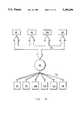
- FIG. 7shows the hierarchical structure of FIG. 4 further including a coordinating controller.
- FIG. 8shows the hierarchical structure of a second preferred embodiment of the present invention including first, second, and third communication media.
- FIG. 9is a table showing the data packet transmitted by a personal comfort sensor.
- FIG. 10shows an example of the second preferred embodiment of the present invention.
- FIG. 11shows the hierarchical structure of a third embodiment of the present invention.
- FIG. 12shows an example of the third embodiment of the present invention.
- FIG. 13shows a zone data packet for one zone sensor and two personal comfort sensors.
- FIG. 14shows the operation of a controller being provided with data from a multiplicity of sensors.
- FIG. 15shows a hierarchical structure for the first embodiment of the present invention where several sensors provide a single controller with data.
- FIG. 16shows the operation of the central receiver.
- FIG. 17shows the operation of a typical zone or personal comfort sensor.
- FIG. 18shows a command data packet such as might be transmitted by a building automation system or by a setup tool.
- FIG. 19shows a setup tool for programming controllers in accordance with the present invention.
- FIG. 20is a block diagram of the setup tool of FIG. 19.
- FIG. 21is a block diagram of the zone sensor of the present invention.
- FIG. 22is a block diagram of the personal comfort sensor of the present invention.
- FIG. 23is a block diagram of the central receiver of the present invention.
- FIG. 24is a block diagram of the controller of the present invention.
- FIG. 1shows a typical building 30 having an air distribution system 32. In this building 30 heat flows to and from the building interior through a series of heat transfer operations.
- Warm airis removed from each zone 34 by the return air stream 46 and is replaced by cool supply air from a terminal unit 48.
- warm return airrejects heat to cool water flowing within the heat exchange coil 52.
- the warm water exiting from the coil 52rejects its heat to refrigerant within a water chiller 54 located elsewhere.
- the refrigerantin turn rejects heat to a condenser 56.
- a heating element in the terminal unit 48can supply the heat, or heat can be extracted at the air handler 50 from water flowing within the heat exchange coil 52.
- the basic control objective in the zone 34 controlled by an air distribution system 32is to add or subtract heat by means of the conditioned air supply so that the net amount of heat gained, lost, and stored within the zone 34 is balanced at a comfortable temperature.
- Conventional variations in this arrangementare contemplated such as, for example, (1) the elimination of the water chiller loop so that the return air itself is in heat exchange relationship with the refrigerant, or (2) the use of a cooling tower instead of the condenser 56.
- FIG. 2shows, from a user's perspective, a single zone 34 incorporating the present invention.
- the single zone 34includes a zone sensor 58 having a microprocessor 61 and user selectable inputs for setpoint 60 and mode of operation 62 (i.e. heating or cooling) as well as a temperature sensor 64 which monitors air temperature.
- the zone sensor 58is also shown in FIG. 21.
- the zone sensor 58is usually located in a fixed position which is both easily accessible to the user, and representative of the temperature in the zone 34. As will subsequently be discussed, the zone sensor 58 may also include a generic sensor input 49.
- the zone sensor 58is preferably powered by a power source 59 such as a battery, and therefore the zone sensor 58 either can be detachable from the representative location, or can be always portable and have no fixed position.
- the power source 59can also be a wired connection to an AC power supply or can be a connection to other power sources such as pneumatic or solar. If a battery power source 59 is used, a battery level monitor 63 is also preferably included. Additionally, if a non-renewable power source such as a battery 59 is used, a hardware timer interrupt is also preferably included in the microprocessor of the zone sensor 58.
- the zone sensor 58is then able to enter a dormant state, akin to sleep, where minimal power is used. Periodically (preferably on the order of a two second interval), the hardware timer interrupt activates the zone sensor 58, and the zone sensor 58 samples its environment by means of the available inputs 60, 62, 64, 49. If the elapsed time since the last transmission of data is less than 30 seconds, the zone sensor 58 then returns to its dormant state. If the elapsed time since the last transmission of data is greater than five minutes, a mandatory transmission of data to a central receiver 66 is made.
- a transmissionis made if any of the following criteria is met: (1) if the absolute value of the difference between the latest temperature and the temperature at the last transmission is greater than twice the temperature range resolution; (2) if the setpoint has changed 1° F. since the last transmission; or if a setup command from a setup tool 320 or a message from a personal comfort sensor 110 has been received. Other criteria are also contemplated. After sampling and after transmitting, the zone sensor 58 returns to the dormant state.
- the zone sensor 58has an objective to responsively communicate information and react to changes in zone conditions.
- the zone sensor 58includes a wireless transmitter 65.
- This wireless transmitter 65is preferably a spread spectrum radio frequency transmitter 65A, but may also be an infrared transmitter 65B, narrow band radio frequency transmitter 65C, or an ultrasonic transmitter.
- the zone sensor 58uses the wireless transmitter 65 to transmit a wireless signal to a receiver portion 67 of a central receiver 66.
- the central receiver 66preferably includes a conventional microprocessor data controller 362 and associated RAM and ROM memory 364.
- the central receiver 66receives the wireless signals from each of a plurality of zone sensors 58 in its receiver portion 67, reformats those signals in a translator portion 69 of the central receiver 66, and retransmits those signals on a first communications medium TX1, for example, a hard wired communications bus 72 connecting the units of the air distribution system 32.
- the central receiver 66is shown in FIG. 23 as including a receiver portion 67 and a translator portion 69.
- the receiver portion 67includes a TX2 receiver 360 which receives transmissions on a second communications medium TX2; a data controller 362 such as a TMS 320C14 microcontroller to control the acquisition of transmission on the second communication medium TX2; and a power supply 366.
- the translator portion 69includes a data buffer and formatter 368 such as a Mitsubishi M50747 microprocessor which receives data packets from the data controller 362 and reformats them, if necessary, in the format of the first communication medium TX1.
- a memory device 364is provided to store such information as valid transactions and lists of valid message transmitters, while an audible tone annunciator 365 is included to provide audible acknowledgements of commands received on the second communications medium TX2.
- the reformatted messagesare dispatched by a TX1 transceiver 370 connected to the first communications medium TX1.
- the transceiver 370allows two way communication between the central receiver 66 and any device connected to the first communications medium TX1. This allows a building automation system 76 or the coordinating controller 102 of FIG. 7 to program or command the central receiver 66.
- the setup tool 320 of FIG. 19can transmit program instructions or commands to the central receiver 66 over the second communications medium TX2.
- FIG. 6shows a data packet 86 included in the zone sensor's wireless transmission.
- This data packet 86is preferably prefixed by a message type 86T and includes an indication of the zone sensor's identity 86A, the zone sensor's setpoint 86C, 86D, the zone sensor's mode of operation 86E, and the current zone temperature 86B.
- the zone sensor 58can also transmit information from the battery level monitor 63 indicating the power level 86F of a battery 59 in the zone sensor 58, and an indication of whether a user has initiated timed override 86G.
- timed override 86Gallows a user, by touching a switch 70, to indicate to a controller 68 of the zone air handling system that the zone 34 should temporarily be treated as occupied rather than unoccupied. After the expiration of a predetermined time-out period, the controller 68 automatically returns the zone 34 to the unoccupied status.
- timed overrideprovides a multifunction way of allowing a user to drive the system and to enter information to the system.
- the switch 70acts as an on/off toggle to indicate occupancy or unoccupancy of a zone respectively. If an automatic time-out is required to return the zone to the unoccupied state, the period of time selected for automatic time-out is large, preferably several hours in length.
- the timed override switch 70 in conjunction with the setpoint 86C or 86Dcan also be used in servicing the system.
- the controller 68can respectively be instructed to enter a permanent override state or to open its damper 74 to a maximum flow rate. A serviceman can then service the system in that particular state.
- controllers 68are generally described herein as controlling the damper 74 of a terminal unit 48, the present invention is not intended to be limited by the controller's application.
- the controller 68could control the operation of the air handler 50, or the water chiller 54 in response to data provided by the present invention.
- the controller 68can control other types of HVAC units (not shown) such as roof top air conditioning units, self-contained units, or packaged terminal air conditioners.
- the controller 68can also control the operation of the zone lighting 38,75 to provide variable intensity lighting in response to user indications of lighting comfort levels, or in response to building management control strategies provided by the building automation system 76.
- FIG. 24shows a block diagram of a controller 68 including a TX1 transceiver 400 for receiving and transmitting messages on the first communications medium TX1.
- the transceiver 400is connected to a message encoder/decoder 402 which encodes or decodes messages received from or to be transmitted on the first communications medium TX1.
- Decoded messagesare supplied to a controller logic unit 404 which uses information from the messages in conjunction with control algorithms to control a load 406 such as a damper 74, a variable speed fan, a compressor, an air conditioning unit, a light or lighting bank 38,75 or other similar devices.
- a memory 408is provided and connected both to the controller logic unit 404 and the message encoder/decoder 402 for storing data, instructions and algorithms.
- Each controller 68 attached to the bus 72has the identification signal 86A for the particular zone sensor 58 or zone sensors 58 located in the controller's zone 34 stored in the memory 408 of the controller 68.
- the controller 68monitors transmissions on the bus 72 for signals emanating from that particular zone sensor 58 or zone sensor 58. Non-relevant data transmissions are received and discarded.
- the controller 68recognizes a data packet 86 from its designated zone sensor(s) 58, the controller 68 controls the position of a damper 74, or the speed of a variable speed fan (not shown), depending upon the mode of operation 86E, the setpoint 86C, 86D, and the temperature 86B provided by the zone sensor 58.
- controller 68modulating zone temperature by modulating damper position
- other ways of modulating zone temperatureincluding the use of variable speed primary air, return air and/or discharge air fans or the use of a variable size orifice.
- FIG. 3shows a block diagram of the wireless communication system and the air distribution system of the present invention.
- a first communications medium TX1such as the hard wired communications bus 72 links a plurality of air handling controllers 68 to each other, to the central receiver 66, and optionally to a building automation system 76.
- the building automation system 76allows the controllers 68 and zones 34 to be centrally monitored and automatically coordinated.
- Each controller 68can exchange information via the first communications medium TX1.
- This first communications medium TX1is implemented as the communications bus 72, which in the preferred embodiment is a twisted pair wire communications link transferring data in a serial fashion.
- the first communications medium TX1can also be implemented as a power line carrier or the like.
- each controller 68can receive setpoints and other commands from the building automation system 76, and can transmit status and other information to the building automation system 76.
- Commands from the building automation system 76can either be directed to a specific controller 68, or can be in the form of a general broadcast to all controllers 68.
- a general system broadcastmight provide outside air temperature or might indicate that the power level of a particular zone sensor 58 has depleted, and that controllers 68 relying on information from that particular sensor should substitute a default sensor.
- the controller 68operates using the last operating mode and setpoints with which the controller 68 has been provided.
- a source 78 of supply air from an air handling unit 50is provided by a supply air duct 80.
- a plurality of branch ducts 82interconnect the supply air duct 80 to the plurality of zones 34 whose environment is to be controlled.
- Each branch duct 82has a damper 74 or its equivalent controlled by the controller 68 of the particular zone 34 or zones 34 to which the branch duct 82 supplies conditioned air.
- Within each zone 34is a zone sensor 58 which transmits information to the central receiver 66 using a second communication medium TX2.
- the second communication medium TX2is preferably spread spectrum radio frequency transmissions where the bandwidth of the transmitted signal is deliberately widened to improve the signal to noise ratio.
- the use of two distinct redundant transmissions on two distinct frequenciesis also preferred to insure that a message is received at its destination even if one frequency is blocked.
- the use of spread spectrum radio frequency transmissions, as opposed to other types of transmissions media including conventional radio frequency transmissions,is preferred because spread spectrum radio frequency transmissions have greater range, and are far less susceptible to interference from building structures and electronic devices. In spread spectrum communications, a spreading algorithm is selected to spread the transmission over a much greater bandwidth than a conventional transmission bandwidth.
- the algorithmspreads the bandwidth of the transmission 100 times as wide as the conventional bandwidth, a source of interference which interferes with 50% of a conventional bandwidth's transmission will only interfere with 0.5% of the same transmission sent with the spreading algorithm.
- multiple spreading algorithmscan be selected so that simultaneous transmissions using different spreading algorithms will, at most, minimally interfere with each other.
- Spreading algorithmsare described in Spread Spectrum Systems, Robert C. Dixon (2nd ed, 1984, John Wiley & Sons, Inc. New York, TK5102.5.D55, ISBN 0-471-88305-3) which is herein incorporated by reference.
- the second communication medium TX2can also be a conventional bandwidth radio frequency transmission, or in some limited circumstances the second communication medium TX2 can be an infrared or ultrasonic transmission.
- the zone sensor 58transmits a zone sensor data packet 86 containing an identification code 86A, a zone mode of operation 86E, a heating or cooling zone setpoint 86C, 86D for that particular mode of operation, and a zone air temperature 86B, as well as battery status 86F and timed override signals 86G.
- the central receiver 66receives the transmissions from each of a plurality of zone sensors 58, checks to see if the transmission itself and the transmitting device are valid, formats each of the transmissions from the zone sensors 58 into a format usable on the first communications medium TX1 and retransmits the zone sensor data packets 86 onto the first communications medium TX1.
- Each of the plurality of controllers 68monitors the first communications medium TX1 for zone sensor data packets 86 emanating from that particular controller's designated zone sensor 58 and controls a branch duct damper 74 in accordance with those signals.
- FIG. 4is a block diagram showing how the essentially hierarchical wireless communication system of the present invention operates.
- a plurality of air distribution controllers 68are linked by the first communications medium TX1 to at least one central receiver 66 capable of receiving transmissions on the second communication medium TX2.
- This central receiver 66receives wireless transmissions on the second communication medium TX2 from a plurality of zone sensors 58.
- These zone sensors 58generally have a logical correspondence to the controllers 68 although several controllers 68 can rely on information from the same zone sensor 58, or alternatively several zone sensors 58 can provide information to the same controller 68. These alternatives will be subsequently described.
- the central receiver 66receives the transmissions on the second communication medium TX2, places the transmissions in the format of the first communications medium TX1, and retransmits the zone sensor information on the first communications medium TX1.
- the central receiver 66also maintains an internal list of valid zone sensors 58 for use in verifying the validity of data packet transmissions. These internal lists are programmed by the building automation system 76 or the setup tool 320, and are an aid in reducing invalid or redundant transmissions on the first communications medium TX1.
- each controller 68recognizes identification codes 86A for particular zone sensors 58, extracts the information accompanying the identification code 86A, and uses that information to modulate airflow in a branch duct 82 or in a zone air handling unit 84 such as an terminal air unit.
- the zone 34 whose environment is to be controlledtypically includes a zone sensor 58, and a drop ceiling 88.
- a supply air duct 80supplying conditioned air from an air conditioning unit, a branch duct 82 connecting the supply air duct 80 to a terminal unit 84, and the terminal unit 84 which supplies the conditioned air to the zone 34 to be controlled.
- a branch duct damper 74controls the flow of conditioned air through the branch duct 82 from the supply duct 80 to the terminal air unit 84.
- a controller 68is operably connected to and in control of the branch duct damper 74.
- a first communications medium TX1such as the bus 72, using twisted pair, power line carrier, cable, or the like links the controller 68 to the central receiver 66, to other controllers 68, and to a building automation system 76 if provided.
- the controller 68controls the position of the branch damper 74, and thereby volume of airflow to the zone 34, in response to information received from the zone sensor 58 over the first communications medium TX1.
- the zone sensor 58 of the present inventionhas no physical connection to the controller 68. Instead, the zone sensor 58 communicates information in the general form of the data packet 86 to the central receiver 66 using a wireless second communication medium TX2 such as spread spectrum radio frequency transmissions.
- the central receiver 66is operably connected to the first communications medium TX1 and retransmits the zone sensor data packet 86 onto the first communications medium where the controllers 68 can access the information in the zone sensor data packet 86.
- FIG. 5is an example of the present invention applied to a pair of distinct buildings 90, 92.
- One building 90has a first floor 94 having two zones Z1, Z2, and a second floor 96 having three zones Z3, Z4, Z5.
- the single story building 92has an interior 98 which has been divided into three zones Z6, Z7, Z8.
- Each zone Z1 through Z8has a controller 68 controlling a supply of conditioned air to the particular zone Z1 through Z8.
- the dampers, the duct systems, the air handling systems, and the air conditioning systemsare not shown, but can be seen in reference to FIGS. 1 through 4.
- each controller 68for each zone Z1 through Z8, and each controller 68 is interconnected by the first communications medium TX1, e.g. the communications bus 72.
- the bus 72is also connected to a single central receiver 66.
- Each zone Z1 through Z8has a single zone sensor which, for the sake of simplifying this example, is also identified as Z1 through Z8.
- Each zone sensor Z1 through Z8monitors environmental conditions and periodically, for instance at five minute intervals, transmits a data packet 86 similar to that shown in FIG. 6 to the central receiver 66 by means of the second communication medium TX2.
- the second communication medium TX2is preferably spread spectrum radio frequency transmissions.
- the zone sensors Z1 through Z8also transmit on every change of state or whenever a user command is entered.
- the central receiver 66receives each transmission, reformats the transmission into the format required by the first communications medium TX1 and retransmits the reformatted information on the first communications medium TX1.
- Each controller 68monitors the transmissions on the first communications medium TX1 and extracts and uses data from a pre-identified zone sensor or zone sensors Z1 through Z8.
- Each controller 68may also respond to a general system broadcast on the first communications medium TX1 indicating, for instance, that a fire has been detected and appropriate measures should be taken.
- zone sensor Z6transmits a data packet 86 containing a zone sensor identification code 86A, zone air temperature 86B and other information to the central receiver 66. This information is retransmitted over the communications bus 72, identified by a particular controller 68Z, and used to regulate the flow of conditioned air to the zone Z6. If the air temperature 86B is above the cooling setpoint 86D of the zone Z6, and the zone Z6 is in the cooling mode 86E, the controller 68Z will provide increased flow of cooled air to the zone Z6.
- the controller 68Zwill call for cooling to the building automation system 76 or to the water chiller 54. The controller 68Z will then act to minimize the amount of heated air allowed into the zone Z6.
- the controller 68Zpreferably includes means for maintaining the best available mode of operation in the event that the designated zone sensor Z6, the primary preferred sensor, should fail. For example, if the controller 68Z does not receive information from its designated primary zone sensor Z6 within a predetermined time frame, such as a five or ten minute period, the controller 68Z monitors transmissions from a secondary zone sensor if available.
- the zone sensor Z7can function as a secondary zone sensor because the zone sensor Z7 is within the same physical space, i.e. the interior 98, and because the controller 68Z has previously been programmed by a building automation system 76 or a setup tool 320 to recognize Z7 as a secondary zone sensor.
- controller 68Zcan continue to operate with actual feedback from the building interior 98 rather than shutting down or controlling airflow based upon some programmed default mode which has no temperature feedback. Furthermore, should the secondary zone sensor Z7 fail, the controller 68Z can recognize the zone sensor Z8 as a tertiary source of information, and continue to supply conditioned air to the zone Z6 using information supplied from the zone sensor Z8. Only when the primary sensor and all designated alternate sensors fail will it be necessary to shutdown or operate in a preprogrammed default mode of operation.
- Such a preprogrammed mode of operationmight compare default setpoints to supply air temperature as measured by a supply air temperature sensor (not shown) hard wired to the first communications medium TX1, or, in a retrofit environment, might continue to operate using information provided by hard wired zone sensors if any such zone sensors remain attached to the system.
- FIG. 7shows the structure of the present invention where a coordinating controller 102 has been added to the hierarchical control system shown in FIG. 4.
- a coordinating controller 102communicates with each of the controllers 68 by means of the communications bus 72, and coordinates the activities of those controllers 68.
- the coordinating controller 102receives operating information such as damper position and zone temperature from the controller 68 and transmits command information such as setpoints and open/close commands to the controllers 68.
- the coordinating controller 102facilitates building monitoring and scheduling on a smaller scale than a building automation system 76, and in fact can comprise an element of a building automation system 76.
- Both the coordinating controller 102 and the building automation system 76include a broadcast function allowing the transmission of system wide commands and data. Examples of the broadcast function include the periodic broadcast of the outside air temperature to all controllers 68, and the broadcast of a command to instruct all controllers 68, or a group of controllers 68, to commence air balancing.
- FIG. 8illustrates the hierarchical structure of a second preferred embodiment of the present invention.
- the second embodimentadds a third communication medium TX3 transmitting personal comfort information from a plurality of personal comfort sensors 110.
- the controllers 68communicate, as before, by means of the first communications medium TX1, i.e. the communications bus 72.
- a plurality of zone sensors 58transmit zone information to the central receiver 66 using a second communication medium TX2 such as spread spectrum radio frequency transmissions.
- the central receiver 66reformats the transmissions from the zone sensors 58 and retransmits the zone information on the first communications medium TX1 for use by the zone controllers 68.
- FIG. 22shows a block diagram of a personal comfort sensor 110.
- the personal comfort sensor 110includes a housing 340 which includes a microprocessor controller 342; a TX3 output device 344 such as a wired connector 344D, an infrared transmitter 344B, a radio transmitter 344A or a spread spectrum RF transmitter 344C; and a power source 346 such as a battery.
- a battery monitor 348is provided to monitor the level of the power source 346 if the power source 346 is depletable.
- the personal comfort device 110is provided with the capability to enter a dormant, power saving state if the power supply 346 is depletable.
- the personal comfort sensor 110also includes various inputs to the microprocessor controller 342 such as a timed override input 350, an air temperature input 352, an air flow input 354, a lighting comfort level input 355, an air quality input 356, a comfort indication input 358 and a generic sensor input 359.
- the personal comfort sensors 110each monitor the conditions within a localized region and transmit the monitored information in a personal comfort data packets 100 to predetermined zone sensors 58.
- the predetermined zone sensors 58then retransmit the personal comfort information to the central receiver 66 either as a separate data packet on the second communication medium TX2, or incorporate the personal comfort information into the zone sensor data packet and send a single transmission for subsequent retransmission on the first communications medium TX1.
- the zone sensor 58 identified as Z10 in FIG. 8receives a transmission from the personal comfort sensor 110a on the third communication medium TX3 and retransmits the information to the central receiver 66 on the second communication medium TX2 for subsequent retransmission on the first communications medium TX1.
- the zone sensor 58 identified as Z11receives transmissions from the personal comfort sensors 110b and 110c on the third communication medium TX3, retransmits the personal comfort information on the second communication medium TX2 to the central receiver 66, which subsequently retransmits the information on the first communications medium TX1.
- the zone sensor 58 identified as the Z12receives transmissions from the personal comfort sensors 110d, 110e, and 110f by means of the third communication medium TX3, and retransmits those personal comfort information packets to the central receiver on the second communication medium TX2, for subsequent retransmission on the first communications medium TX1.
- the use of a third communication medium TX3prevents the central receiver 66 from being overloaded with incoming transmissions, while facilitating the grouping of sensors in logical arrangements.
- the third communication medium TX3is preferably a wireless communications medium distinct from the second communication medium TX2 so that the third and second communication mediums TX3,TX2 do not interfere with each other's transmissions.
- the second communication medium TX2is spread spectrum radio frequency
- the third communication medium TX3is preferably infrared, ultrasonic, or narrow band radio frequency transmissions.
- the third communication medium TX3can also be a hard wired connection between the personal comfort sensor 110 and the zone sensor 58 such as a cable, a twisted pair link, or an optic fiber link.
- the third communications medium TX3can be the same communications medium as the second communications medium TX2, if the two media are readily distinguishable, such as, for example, by the use of distinct frequencies.
- distinct, non-interfering spreading algorithmscould be employed by the second and third communications media TX2, TX3.
- FIG. 9shows a personal comfort data packet 100 for transmission by a personal comfort sensor 110.
- That data packet 100includes a personal comfort identification code 100A, air temperature 100B, air flow 100C, air quality 100D, a personal comfort indicator 100D that the user is either too warm or too cold, a battery status 100F, the initiation of timed override 100G by a user, and a lighting comfort level indication 100H that zone lighting is too dim or too bright.
- the personal comfort data packet 100is prefixed by a message type 100T.
- the personal comfort sensor 110can include an accompanying generic sensor input 359 which allows, for example, a humidity sensor (not shown) to be connected to a personal comfort sensor 110 and to forward humidity data 100I. At different times, other sensors can also be connected to the generic sensor input 359 such as an occupancy sensor. In this case, the personal comfort data packet 100 indicates the occupied/unoccupied status 110i of the area being monitored by the occupancy sensor.
- FIG. 2shows a personal comfort sensor 110 transmitting this information by infrared transmission on the third communication medium TX3 to an infrared receiver 112 included in the zone sensor 58.
- the zone sensor 58receives the transmission of a personal comfort data packet 100 from the personal comfort sensor 110 and appends the personal comfort sensor data packet 100 to the zone sensor's data packet 86. This is subsequently discussed with regard to FIG. 13.
- a single transmissionis then made to the central receiver 66 by the zone sensor 58 on the second communication medium TX2.
- the central receiver 66then either places the zone sensor transmission on the first communications medium TX1 unaltered, or separates the zone sensor data packet 86 and the personal comfort data packet 100 from each other and transmits each on the first communications medium TX1 independently.
- the personal comfort sensor 110 shown in FIG. 2also includes a comfort indication input 358 such as a comfort indicator switch 114 having a neutral position, a warmed air request position and a cooled air request position which a user can use to indicate that the user is too warm, or too cold.
- a comfort indication input 358such as a comfort indicator switch 114 having a neutral position, a warmed air request position and a cooled air request position which a user can use to indicate that the user is too warm, or too cold.
- the user's indicationis incorporated into the personal comfort sensor data packet 100 as the comfort indicator 100E and transmitted to the relevant zone sensor 58.
- the comfort indicator switch 110is described as having a neutral position, a warmed air request position, and a cooled air request position, the comfort indicator switch 110 can have further positions such as energy efficiency.
- Zone energy efficiencyis an optional user input which allows the user to indicate to the controller 68 that the user is more interested in energy efficiency and energy conservation than in personal comfort and that the controller 68 can shift the boundaries of comfort control in an energy efficient or energy conserving manner.
- Energy efficiencyallows a user to tell the zone controller 68 that the user is more interested in energy efficiency and in energy conservation than in the user's personal comfort.
- the controller 68is then authorized to automatically vary the cooling setpoint, the heating setpoint, and the mode of operation so as to condition the zone in the most energy efficient manner.
- the heating setpointwhen operating in an energy efficient mode on a cool day, the heating setpoint might be automatically lowered 2° F. so that the heating system operates less often. Similarly, on a warm day the cooling setpoint might be automatically raised 3° F. so that the cooling system operates less often.
- the personal comfort sensor 110also includes a lighting comfort level input 100I which allows a user to indicate that lighting 38,75 is too bright, too dim, or should undergo a change of state from off-to-on, or on-to-off.
- the controller 68receives the lighting comfort level input 100H and controls the zone lighting system 75 accordingly.
- FIG. 10illustrates an example of the second preferred embodiment.
- a building 118 having a first floor 120 and a second floor 122is divided into three zones 124, 126, 128, each zone 124, 126, 128 having a zone sensor 58 respectively designated Z13, Z14, Z15.
- each floor 120, 122is provided with a central receiver 66, which might be necessary if the material 121 separating the floors 120, 122 significantly impedes the transmissions on the second communications medium TX2.
- the central receiver 66 on the second floor 122receives data packets 86, 100 transmitted from the zone sensor Z13 and the personal comfort sensors 110g, 110h, 110i, and 110j; and retransmits the data packets 86, 100 on the first communications medium TX1 for use by the controllers 68a, 68b.
- the central receiver 66 on the first floor 120receives data packets 86, 100 transmitted from the zone sensors Z14, Z15 and the personal comfort sensors 110k, 110L and retransmits the data packets 86, 100 on the first communications medium TX1 for use by the controllers 68c, 68d, 68e.
- the zone sensor Z13transmits zone sensor information for use by controller 68a and 68b, the zone sensor Z14 transmits information for use by the controller 68c, and the zone sensor Z15 transmits information for use by the controllers 68d and 68e.
- the zone 124might be an office area having half walls 130 separating individual office areas 132. In a situation where the sun heats a first end 134 of the zone 124, and the wind cools a second end 136 of the zone 124, the placement of a single zone sensor Z13 might be impossible to provide uniform air temperature throughout the zone 124.
- some or all of the individuals areas 132can be provided with personal comfort sensors 110, preferably fixed in place unlike the personal comfort sensor of FIG. 2.
- Each personal comfort sensor 110transmits personal comfort information to the zone sensor Z13 by means of the third communication medium TX3.
- the zone sensor Z13transmits all of the information from the zone 124 to the central receiver 66, including the zone sensor's own information as well as the personal comfort sensor information.
- the central receiver 66then transmits the zone information on the first communications medium TX1 where the information is received by the controller 68a and 68b.
- Controller 68apreferably controls the environment in the zone 124 using the temperature information provided by the personal comfort sensor 110g, the personal comfort sensor 110h and the zone sensor Z13.
- the controller 68bpreferably controls the environment of the zone 124 using temperature information provided by the personal comfort sensor 110i, the personal comfort sensor 110j, and the zone sensor Z13.
- the zone 126is controlled solely in response to zone sensor Z14, while the controllers 68d and 68e control the zone 128 by averaging the air temperatures reported by the zone sensor Z15 and the personal comfort sensors 110k and 110L.
- a number of approaches, some of which are discussed in connection with FIG. 14,can be used to allow the controllers 68 to control the environment using multiple sensors. These approaches include averaging the air temperature received from each of these sensors, weighting the air temperatures and/or setpoints received from the sensors, selecting mode of operation in accordance with the mode requested by a majority of sensors, or controlling the environment to minimize the largest deviation from setpoint of any one of the sensors.
- FIG. 11shows the hierarchical structure of a third embodiment of the present invention.
- the zone sensors 68 and the personal comfort sensors 110can each transmit on either the third communication medium TX3 or on the second communication medium TX2.
- the zone sensors 68 and the personal comfort sensors 110be provided with the capability to transmit on either one or the other of the second or third communications media TX2, TX3 and not on both media. This selection is expected to be made by the system designer.
- three zone sensors 138 and two personal comfort sensors 140transmit zone data packets 86 to the central receiver 66 on the second communication medium TX2.
- a personal comfort sensor 142also transmits data on the third communication medium TX3 to zone sensor 138a for incorporation into the zone data packet 86 of zone sensor 138a and subsequent retransmission to the central receiver 66.
- Two additional personal comfort sensors 144a and 144btransmit data to the zone sensor 138b by means of the third communication medium TX3 for subsequent retransmission to the central receiver 66 on the second communication medium TX2.
- the central receiver 66reformats the zone data packets 86 and retransmits those zone data packets on the first communications medium TX1 where the zone data packets 86 can be accessed by the controllers 68.
- the third embodimenthas the advantage that airflow and other data sensed by the personal comfort sensors 110 can be supplied to the controllers 68 without the necessity of implementing a third communication medium TX3. Additionally, the interchangeability of the zone sensors 58 and the personal comfort sensors 110 provides greater user flexibility in designing economical and efficient air distribution systems, particularly where there is a cost disparity between either the personal comfort sensors 110 and the zone sensors 58, or between the second communication medium TX2 and the third communication medium TX3. If desired, a zone sensor 58 can be used transmitting on the third communication medium TX3.
- FIG. 12is an example of the third embodiment of the present invention as applied to a two story building 146.
- the two story building 146has two floors 148 and 150, the first floor 148 of which includes two large areas 152 and 154.
- the large area 154is a single zone controlled by a single controller 156 and a single zone sensor 158.
- the other large area 152is serviced by two controllers 160 and 162.
- the controller 160receives zone data packets 86 from a zone sensor 164 and a personal comfort sensor 166 connected to the zone sensor 164 by a cable type link 168 which implements a third communication medium TX3.
- the controller 162is supplied with zone sensor data packets 86 by a zone sensor 170 and a personal comfort sensor 172.
- the zone sensor 170is provided with data from the personal comfort sensor 172 over a fiber optic link 174 which implements the third communication medium TX3.
- the second story 150 of the building 146includes offices 176 separated by half walls 178.
- Each office 176includes a portable personal comfort sensor 180 which transmits zone data packets 86 over the second communication medium TX2 to the central receiver 66 for subsequent retransmission on the first communications medium TX1 to the controller 68.
- FIG. 12also illustrates the use of redundant central receivers 66, where each floor 148, 150 is provided with a pair of identical central receivers 66.
- Each of the central receivers 66is expected to act as a backup to the other central receiver 66. Consequently, each central receiver 66 is constantly retransmitting all transmissions received on the second communications medium TX2. Effectively, while both central receivers 66 are operative, each zone data packet 86 is received redundantly by the relevant controller 68. If the redundant transmissions by the redundant receivers 66 begins to degrade the first communications medium TX1, it is preferable to modify the data files within the memory 364 so that a minimum time between transmissions to any particular controller 68 is formed.
- This minimum time limitis mathematically determined to minimize collisions on the first communications medium TX1, and could be on the order of 30 seconds.
- the redundant central receiver 66can be instructed to operate normally with the exception that no transmissions on the first communications medium TX1 are made unless an "active" central receiver 66 fails to transmit an expected data packet 86, 100 or command within a preset time period.
- the execution of duplicate instruction or the response to duplicate data packets 86 by the zone controllersis immaterial because the instructions and the redundant zone data packets 86 are identical.
- FIG. 13shows a zone data packet 86 such as might be sent by the zone sensor 138b of FIG. 11 and includes the data from the personal comfort sensors 144a and 144b.
- the data packet 86includes three sections 182, 184, 186 respectively directed to the data from the zone sensor 138b, the personal comfort sensor 144a and the personal comfort sensor 144b.
- Each section 182, 184, 186is preferably preceded by a message type respectively 182T, 184T, 186T.
- the zone sensor section 182includes a zone sensor code 190, zone air temperature 192, heating setpoint 194, cooling setpoint 196, mode of operation 198, battery status 200, and timed override status 202, for the zone sensor 138b.
- the data packet 86also includes the data section 184 from the personal comfort sensor 144a including the personal comfort sensor identification code 206, personal comfort sensor air temperature 208, airflow 210, air quality 212, user's lighting comfort level 213, user's comfort indicator 214, battery status 216, and timed override 218.
- the third section 186 of the data packet 86is the data associated with the personal comfort sensor 144b including the personal comfort sensor identification code 220, air temperature 222, airflow 224, air quality 226, user's lighting comfort level 227, user comfort indicator 228, battery status 230, and timed override 232.
- Each zone sensor in the system shown in FIG. 11will transmit a data packet of this length.
- the section 186will be blank as a second personal comfort sensor does not report to the zone sensor 138a.
- both the sections 184, 186will be blank as no personal comfort sensor reports to the zone sensor 138c.
- the sections 182, 186will be left blank as no zone sensor or second personal comfort sensor is present.
- the personal sensor identification code 206 of the personal comfort sensor 140might be copied to the zone sensor identification code 190 for ease of identification by the controllers 68.
- the use of fixed length transmissionsenables the central receiver 66 to recognize the completeness of the data packet 86, and reformat and retransmit the data packet on the first communications medium TX1.
- a specific controller 68bis able to monitor the first communications medium TX1 for data packets 86 having the identification code for zone sensor 138b, personal comfort sensor 144a, and/or personal comfort sensor 144b.
- the present inventionneed not be implemented using a single fixed length data packet. For instance, variable length data packets identified with stop/start identifiers could be implemented, or each sensor could transmit an independent and unique data packet.
- FIG. 14is a flow chart showing the operation of a controller 68 being provided with data from a multiplicity of zone and personal comfort sensors 58, 110.
- the operationis shown by flow chart 236 where, after an initialization step 238, the controller 68 enters an endless loop 240.
- the controller 68constantly monitors the first communications medium TX1 for activity, and determines if that activity is either a command from a building automation system 76 or a setup tool 320, or a zone data packet 86 from one of a plurality of predesignated zone sensors 58 and personal comfort sensors 110.
- the message type 86T, 100T, 182T, 184T, 186T and 104A prefixed to each data or command packetfacilitates this determination.
- the controller 68determines if activity on the first communications medium TX1 is a valid command from a building automation system 76 or a setup tool 320, and if so, executes the command and recommences monitoring the first communications medium. If the activity on the first communications medium TX1 is information in the form of a zone sensor data packet 86, or if a predetermined time period (such as five minutes) has passed since activity has been detected on the first communications medium TX1, the controller 68 decides that a failure has occurred and determines which alternate zone sensor data should be used so as to maintain the best available mode of operation. In flow chart 236 each primary sensor has an alternate secondary sensor, and an alternate tertiary sensor.
- zone sensors Z6, Z7 and Z8 from FIG. 5are respective examples of a primary, secondary and tertiary zone sensor.
- a timer for the primary sensor Z6the sensor whose data should be used as the basis for controlling the zone environment, is checked to see if the timer indicates a failure by the sensor to provide data within the predetermined time period. If the timer has not expired, the data from the primary sensor Z6 is used. If the primary sensor Z6 has failed to provide recent data, the controller 68 at step 252 attempts to substitute a predesignated secondary sensor Z7 for the primary sensor Z6.
- This secondary sensor Z7might be a personal comfort sensor 110 or might be the zone sensor 58 of an adjacent or similar zone.
- a timercan also be associated with the secondary sensor, and if the secondary sensor Z7 has provided recent data, that data is used at step 254. If the secondary sensor Z7 has failed to provide data within a predetermined time period, then a tertiary sensor Z8 might be substituted at steps 256 and 258 if the tertiary sensor Z8 has not failed. If all designated sensors have failed or if no sensor has provided fresh data, which might occur in the event of a component or partial system failure, the controller 68 operates using predefined default parameters at step 260. These predefined default parameters might be a preset mode of operation, i.e. minimum damper position, or might instruct the controller 68 to use the last valid data packet 86 from the primary sensor Z6 as a basis for modulating zone temperature. Alternatively, the controller 68 can either be instructed to supply air to the zone 34 using default setpoints and hard wired sensors such as supply air temperature sensors, or the controller 68 can be instructed to terminate operations.
- predefined default parametersmight be a preset mode of operation
- the controller 68selects a mode of operation.
- the mode of operationis the mode 86E designated in that particular zone sensors data packet 86.
- the controller 68determines if such a single sensor system is being used and, if so, uses the mode 86E and data at step 264 from that sensor's data packet 86.
- step 274shows a voting arrangement where the mode of operation is selected based upon the modes requested in the zone sensor data packets 86 by the majority of sensors 268, 270, 272 at step 276. If no majority exists, the mode of operation is selected at 278 using the mode requested by the sensor with the largest deviation from setpoint. If no such sensor exists, the existing mode is continued at step 282.
- the damper 74is controlled at step 284 using either a temperature average from all designated sensors as compared to a master setpoint, or by using a representative sensor.
- the master setpointcan be explicitly designated, or can be implicitly designated by its order in the controller's data structure.
- either the sensor temperature data or the zone setpointcan be determined using a weighted average. For example, in a three sensor system two peripheral sensors might have their setpoint and temperature information weighted at 30% each while a centered sensor might have its setpoint and temperature data weighted at 40%.
- a building automation system 76 or a setup tool 320is used to initially convey the selection of the zone sensor system to the controller's 68, and to subsequently alter any parameters. In the event of a conflict between the building automation system 76 and the setup tool 320, the building automation system 76 will override the setup tool 320.
- FIG. 16shows the operation of the central receiver 66 in the form of a flow chart 286.
- the flow chart 286begins with an initialization routine at step 288 and then constantly monitors the second communication medium TX2 at step 290. Messages such as data packets 86,100 or commands received on the second communication medium TX2 are checked for validity at step 292. If the message is valid at step 292, the message type 104A, 86T, 100T, 182T is checked to see if the message is a setup command at step 298. If so, an audible tone is sounded at step 299 and the message data is added to the internal list. The validity of the message transmitter itself is checked against an internal list of valid transmitters at step 296.
- the messageis reformatted at step 294 into the data format used on the first communications medium TX1 and transmitted on the first communications medium TX1 at step 300.
- the present inventionis disclosed in terms of reformatting the data from the second communication medium to the format used in the first communications medium TX1, it should be recognized that these data formats could be similar and the reformatting step omitted.
- FIG. 17is a flow chart 302 showing the operation of a typical zone or personal comfort sensor 58, 110.
- the zone or personal comfort sensor 58, 110is activated or awakened from a dormant state at step 305 by either (1) a hardware timed interrupt on the order of every two seconds, (2) the receipt of a personal comfort data packet 100 from a personal comfort sensor 110, (3) a change of state such as an input from the timed override switch 70, the setpoint device 60, or the mode of operation selector 62, or (4) the receipt of a command data packet 104 from a setup tool 320.
- the zone or personal comfort sensor 58, 110then monitors the environment of the zone 34 at step 306 by sampling and filtering the temperature 64, by sampling the timed override switch 70 and the mode of operation switch 62, and by sampling a setpoint wheel 60.
- a software timeris periodically checked at step 308 to ensure that the zone or personal comfort sensor 58, 110 sends data no more often than 30 seconds but at least every five minutes, whether or not a change of state has occurred. Additionally, any time a change of state occurs or a command or data packet 104,100 has been received, data is transmitted at steps 310 and 312.
- the zone sensor 58determines if a command data packet 104 has been received either by a physical connection 316 or by the third communications medium TX3.
- the zone or personal comfort sensor 58, 110goes to sleep at step 315. Going "dormant” is a method of conserving a non-renewable power source 59 such as a battery 59. If the power source 59 is continually renewed, it is not necessary to render the zone sensor 58 or personal comfort sensor 110 dormant. Each time data is transmitted, the software timer accumulating time since the last transmission is reset. Depending upon which embodiment of the present invention is being implemented, the zone or personal comfort sensor 58, 110 can transmit data at step 312 on either the second communication medium TX2, or the third communication medium TX3. Monitoring is then recommenced at step 306.
- FIG. 18shows a command data packet 104 containing a message type 104A, the controller identification code 104B of the controller 68 to which the command data packet 104 is being directed to, a zone identifier 104C identifying a particular zone 34 being assigned to the controller 68, designated by the controller identificator code 104B, and instructions 104D as to whether to add or subtract the zone 34 to or from the controller's memory 408. Additional commands can indicate that the controller's memory 408 should be purged 104E of zone assignments and data; that the data from the zone 34 be averaged 104F with other assigned zones 34; or the data from the zone 34 be used as a secondary or tertiary backup sensor.
- commandscan indicate, as subsequently discussed, that the zone setpoint 86C or 86D be used as a master setpoint 104G for comparison with averaged or weighted temperature information from a plurality of zones 34.
- a master setpoint 104Gcan be a 1 bit designation or, if setpoints are weighted by percentage between a number of zone sensors 58, the designation can be a weighted percentage of 100%. For example, in a three sensor zone, such as zone 128 of FIG. 10, having two interior sensors Z15,110k and one peripheral sensor 100L, the peripheral sensor 100L might be weighted 40% and the interior sensors Z15, 110k weighted 30% each.
- the controller 58averages the temperature data from the three sensors, and compares that average to a setpoint determined from 40% of the peripheral zone setpoint 110L and 30% of each of the interior zone setpoints Z15,110k. However, if the peripheral zone sensor 110L was the master setpoint, the peripheral zone sensor 110L would be weighted 100% and the interior zone sensors Z15,110k each be weighted 0 %.
- the controllers 68receives their initial and subsequent programming and commands from either a building automation system 76, a coordinating controller 102, or a setup tool 320 by means of the first communication medium TX1.
- the setup tool 320uses a non-physical link such as the second communication medium TX2 and possibly the third communications medium TX3 to provide programming, information or commands to any particular controller 68 by means of the central receiver 66.
- the setup tool 320can be provided with a transmitter 322 so that programming instructions can be directly transmitted on the second communications medium TX2 to the central receiver 66 and thereafter to the controller 68.
- the setup tool 320can also, or alternatively, be provided with a wired connector such as an electrical plug 324 capable of operatively interfacing with a mating connection 316 on a zone sensor 58 or a personal comfort sensor 110.
- the setup tool 320 programming instructionsare then indirectly transmitted by the zone sensor 58 to the central receiver 66 for subsequent retransmission to the controller 68.
- the setup tool'smay also directly or indirectly transmit programming instructions on the third communications medium TX3 using an infrared transmitter 326 or the electrical connection 324 to a personal comfort sensor 110, respectively.
- the setup tool 320typically includes a housing 328 containing a microprocessor controller 330; and output device 332 such as a radio transmitter 322, a wired connector 324, or an infrared transmitter 326; a power source 334 such as a battery or a household AC plug connector; a keyboard 336; a display 338; a number of input switches 104D, 104E and 104F; a power indicator 335; a transmit indicator 337; and a generic sensor input 104H.
- the generic sensor input 104H(subsequently discussed) allows a humidity or temperature sensor to be attached to the setup tool 320 and provide a sensed signal value for transmission through the hierarchical communications system.
- the wired connector 324may be designed to provide power from the setup tool 320 to a zone sensor 58 or a personal comfort sensor 110.
- the setup tool 320may parasitically draw power from a zone sensor 58 or a personal comfort sensor 110 or use the transmitter of a zone sensor 58 or a personal comfort sensor 110 by way of the wired connector 324.
- the keyboard 336 and display 338allow a user of the microprocessor controller 330 to construct program instructions and commands and transmit these programmed instructions as data packets 104.
- the transmissionsmay be directly on the second communications medium TX2 to the central receiver or indirectly on the third communications medium TX3 to the central receiver 66 by means of a zone sensor 58.
- Commands from the setup tool 320are transmitted in the same format shown in FIGS. 6, 9, and 13 and described in connection with FIGS. 7 and 18, except that the message type 104T is varied to indicate that a command packet 104 as opposed to a sensor data 86 is being transmitted to a particular controller 68.
- the message typealso tells the controller 68 to look for the controller's own identification designator at the location 104B in the command data packet 104 instead of looking for the zone sensor identification code 86A.
- an audible signalis sounded by the audible annunciator 365. This provides an acknowledgement to the user of the setup tool 320 that the command has been received. It is highly advantageous to receive this acknowledgement in a one-way communication system such as that of the present invention. If desirable the audible tones may be coded or varied to indicate various responses to the command.
- the present inventionalso contemplates a generic sensor input connection 49, 104H, 359 respectively associated with the zone sensor 58, the personal comfort sensor 110, and the setup tool 320.
- the generic sensor input 49, 104H, 359allows an external device (not shown) such as a humidity or occupancy sensor to be attached to the zone sensor 58, the personal comfort sensor 110, or the setup tool 320.
- the zone sensor 58, the personal comfort sensor 110, or the setup tool 320recognizes the attachment of a generic sensor to the generic sensor input 49, 104H, 359, identifies the type of generic sensor, and thereafter uses the generic sensor in a conventional manner. Numerous advantages are provided in the areas of system flexibility, as well as in system calibration and system problem diagnosis.
- the generic sensor input 49, 104H, 359can also be used as an external power supply attachment for a zone sensor 58, a personal comfort sensor 110, or a setup tool 320 in need of additional or supplemental power.
- the generic sensor input 49, 104Hmay also be used as the interface 316 which allows a setup tool 320 having a connector 324 to plug that connector 324 into a zone sensor 58 or a personal comfort sensor 110.
- powermay be provided to the setup tool 320 from the zone sensor 58 or the personal comfort sensor 110 by means of the generic sensor input 249, 104H.
- Customized air balancingis also contemplated by the present invention. Balancing is advantageous for two situations. Firstly, system balancing is required to balance the central air conditioning plant against the branches 82 to ensure that the HVAC system is capable of providing design airflows to all system components under maximum airflow conditions. Secondly, zone balancing is required to satisfy specific zone operating conditions such as the elimination of eddy or tornado-like effects in hallways, and the elimination or modification of extreme pressure zones.
- balancing dampers 350 in the branch duct lines 82, and air flow meters 352 also in the branch duct lines 82,are used to balance the flow of air throughout the system. This is typically an iterative process wherein an air flow setpoint for each branch duct line 82 is determined by a system designer, and the balancing damper 350 in each duct 82 throughout the system is iteratively adjusted until all design airflow requirements are reached.
- the iterative processcan be substantially eliminated by causing the building automation system 76 to simultaneously initiate balancing throughout the system.
- Each controller 68is provided with an airflow setpoint, and when the signal from the building automation system 76 is received on the first communications medium TX1, the controller 68 begins to adjust its balancing damper 350 while comparing measured airflow from the air flow sensor 253 to the airflow setpoint. Since all the controllers 68 in the system are doing this simultaneously, air balancing can be quickly accomplished.
- the present inventionfacilitates rebalancing zones and localized portions of the air distribution system. Often the design airflow setpoint is subsequently found to be inadequate to meet the needs of a particular zone or group of zones. This may occur because pressure gradients cause too much or too little airflow into a given zone or group of zones, or because unforeseen conditions such as heat generating equipment or external sunlight exposure were not taken into account.
- the air distribution systemcan use its broadcast function to cause a particular zone or group of zones to rebalance a localized portion of the air distribution system.
- the localized balancingis similar to system balancing on a more restrictive scale.
- Each controller 68is provided with an airflow setpoint. When instructed to do so by the building automation system 76, the controller 68 adjusts its balancing damper 350 until measured airflow approximates the airflow setpoint.
- the setup tool 320can also cause rebalancing to occur.
- indications of personal discomfort as received from the personal comfort sensors 110 using the comfort indication input 358can be logged. If a pattern emerges that a particular zone or group of zones is consistently too warm or too cold, a particular controller 68 can automatically initiate rebalancing of its particular zone to a new airflow setpoint which may be adjusted, for example, by a factor of 5 percent from the previous airflow setpoint. The controller 68 may itself also request that the building automation system 76 evaluate rebalancing the particular group of zones that the controller 68 is a member of. If the controller 68 is provided with the identification codes of the other controller 68 in its particular localized portion of the air distribution system, the controller 68 can issue a broadcast message directly to those controllers 68 to initiate a localized rebalancing of the air distribution system.
- the communications media describedmay conform to the communications protocol standards being developed by the ASHRAE STANDARDS PROJECT Committee as defined in "BACNet-A Data Communications Protocol for Building Automation and Control Networks, Working Draft No. 4", SPC-135P-.015, ASHRAE 1990. This publication is hereby incorporated by reference.
- the BACNet-A Data Communications Protocoladdresses general system broadcasts, specific transmissions and treatment of existing proprietary protocols.
- controllers referred to hereinare not intended to be limited to control of airflow, and the invention is intended to encompass all applications requiring the transfer of data between a sensor and a controller. All such modifications and alterations are intended and contemplated to within the spirit and scope of the present invention.
Landscapes
- Engineering & Computer Science (AREA)
- Chemical & Material Sciences (AREA)
- Combustion & Propulsion (AREA)
- Mechanical Engineering (AREA)
- General Engineering & Computer Science (AREA)
- Physics & Mathematics (AREA)
- Human Computer Interaction (AREA)
- General Physics & Mathematics (AREA)
- Computer Networks & Wireless Communication (AREA)
- Power Engineering (AREA)
- Automation & Control Theory (AREA)
- Signal Processing (AREA)
- Remote Sensing (AREA)
- Mathematical Physics (AREA)
- Fuzzy Systems (AREA)
- Health & Medical Sciences (AREA)
- Biomedical Technology (AREA)
- Fluid Mechanics (AREA)
- Selective Calling Equipment (AREA)
- Air Conditioning Control Device (AREA)
Abstract
Description
Claims (43)
Priority Applications (9)
| Application Number | Priority Date | Filing Date | Title |
|---|---|---|---|
| US07/770,055US5390206A (en) | 1991-10-01 | 1991-10-01 | Wireless communication system for air distribution system |
| EP96116981AEP0759586A1 (en) | 1991-10-01 | 1992-09-24 | Setup tool for a wireless communications system |
| PCT/US1992/008112WO1993007549A2 (en) | 1991-10-01 | 1992-09-24 | Wireless communication system for air distribution system |
| AU26939/92AAU2693992A (en) | 1991-10-01 | 1992-09-24 | Wireless communication system for air distribution system |
| EP92920741AEP0606335B1 (en) | 1991-10-01 | 1992-09-24 | Wireless communication system for air distribution system |
| CA002120154ACA2120154C (en) | 1991-10-01 | 1992-09-24 | Wireless communication system for air distribution system |
| US08/064,325US5361985A (en) | 1991-10-01 | 1993-05-20 | Setup tool for a wireless communications system |
| US08/064,387US5385297A (en) | 1991-10-01 | 1993-05-21 | Personal comfort system |
| US08/068,021US5341988A (en) | 1991-10-01 | 1993-05-27 | Wireless air balancing system |
Applications Claiming Priority (1)
| Application Number | Priority Date | Filing Date | Title |
|---|---|---|---|
| US07/770,055US5390206A (en) | 1991-10-01 | 1991-10-01 | Wireless communication system for air distribution system |
Related Child Applications (3)
| Application Number | Title | Priority Date | Filing Date |
|---|---|---|---|
| US08/064,325DivisionUS5361985A (en) | 1991-10-01 | 1993-05-20 | Setup tool for a wireless communications system |
| US08/064,387DivisionUS5385297A (en) | 1991-10-01 | 1993-05-21 | Personal comfort system |
| US08/068,021DivisionUS5341988A (en) | 1991-10-01 | 1993-05-27 | Wireless air balancing system |
Publications (1)
| Publication Number | Publication Date |
|---|---|
| US5390206Atrue US5390206A (en) | 1995-02-14 |
Family
ID=25087333
Family Applications (4)
| Application Number | Title | Priority Date | Filing Date |
|---|---|---|---|
| US07/770,055Expired - LifetimeUS5390206A (en) | 1991-10-01 | 1991-10-01 | Wireless communication system for air distribution system |
| US08/064,325Expired - LifetimeUS5361985A (en) | 1991-10-01 | 1993-05-20 | Setup tool for a wireless communications system |
| US08/064,387Expired - LifetimeUS5385297A (en) | 1991-10-01 | 1993-05-21 | Personal comfort system |
| US08/068,021Expired - LifetimeUS5341988A (en) | 1991-10-01 | 1993-05-27 | Wireless air balancing system |
Family Applications After (3)
| Application Number | Title | Priority Date | Filing Date |
|---|---|---|---|
| US08/064,325Expired - LifetimeUS5361985A (en) | 1991-10-01 | 1993-05-20 | Setup tool for a wireless communications system |
| US08/064,387Expired - LifetimeUS5385297A (en) | 1991-10-01 | 1993-05-21 | Personal comfort system |
| US08/068,021Expired - LifetimeUS5341988A (en) | 1991-10-01 | 1993-05-27 | Wireless air balancing system |
Country Status (5)
| Country | Link |
|---|---|
| US (4) | US5390206A (en) |
| EP (2) | EP0606335B1 (en) |
| AU (1) | AU2693992A (en) |
| CA (1) | CA2120154C (en) |
| WO (1) | WO1993007549A2 (en) |
Cited By (165)
| Publication number | Priority date | Publication date | Assignee | Title |
|---|---|---|---|---|
| US5595342A (en)* | 1993-05-24 | 1997-01-21 | British Gas Plc | Control system |
| US5629590A (en)* | 1993-10-19 | 1997-05-13 | Futaba Denshi Kogyo Kabushiki Kaisha | Rotational drive control device for variable speed drive motor |
| US5751572A (en)* | 1996-06-22 | 1998-05-12 | Carrier Corporation | HVAC communication network |
| US5781708A (en)* | 1994-09-13 | 1998-07-14 | Intermec Technology, Inc. | Integral bar code printer and reader system and method of operation |
| US5915473A (en)* | 1997-01-29 | 1999-06-29 | American Standard Inc. | Integrated humidity and temperature controller |
| US5927398A (en)* | 1996-06-22 | 1999-07-27 | Carrier Corporation | Device identification system for HVAC communication network |
| EP0833288A3 (en)* | 1996-09-30 | 2000-01-19 | Siemens Aktiengesellschaft | Method for radio transmission of measured data of sensors and radio alarm system |
| US6053001A (en)* | 1996-08-27 | 2000-04-25 | Sanyo Electric Co., Ltd. | Controller of air conditioner |
| US6152375A (en)* | 1999-04-22 | 2000-11-28 | Robison; Jerry L. | Remote control thermostat system for controlling electric devices |
| US6176436B1 (en)* | 1997-09-19 | 2001-01-23 | Pentech Energy Solutions, Inc. | Method and apparatus for energy recovery in an environmental control system |
| US6237854B1 (en)* | 1999-08-30 | 2001-05-29 | Ed Avni | Air conditioning automatic shut-off system |
| US6275166B1 (en) | 1999-01-19 | 2001-08-14 | Architron Systems, Inc. | RF remote appliance control/monitoring system |
| US6304176B1 (en)* | 1998-09-30 | 2001-10-16 | Rockwell Technologies, Llc | Parasitically powered sensing device |
| EP0908684A3 (en)* | 1997-10-08 | 2002-02-13 | Carrier Corporation | Remote control unit |
| US20020047775A1 (en)* | 1999-01-19 | 2002-04-25 | Del Castillo Byron | RF remote appliance control/monitoring network |
| US6380860B1 (en) | 1999-12-14 | 2002-04-30 | Joseph R. Goetz | Portable wireless cellular fire alarm system apparatus and method |
| US20020130692A1 (en)* | 1999-06-28 | 2002-09-19 | Broadcom Corporation | Current-controlled CMOS logic family |
| WO2002075227A1 (en)* | 2001-03-14 | 2002-09-26 | Hussmann Corporation | Distributed intelligence control for commercial refrigeration |
| US6513723B1 (en) | 2000-09-28 | 2003-02-04 | Emerson Electric Co. | Method and apparatus for automatically transmitting temperature information to a thermostat |
| US20030037555A1 (en)* | 2000-03-14 | 2003-02-27 | Street Norman E. | Distributed intelligence control for commercial refrigeration |
| US20030051080A1 (en)* | 1991-10-01 | 2003-03-13 | Mahany Ronald L. | Radio frequency local area network |
| US20030078006A1 (en)* | 1988-08-04 | 2003-04-24 | Mahany Ronald L. | Remote radio data communication system with data rate switching |
| US20030112767A1 (en)* | 1991-10-01 | 2003-06-19 | Meier Robert C. | Communication network providing wireless and hard-wired dynamic routing |
| US6584786B2 (en)* | 2000-05-05 | 2003-07-01 | Stefano Tavolazzi | Food preservation refrigerator closure member carrying an interface for controlling its operation |
| WO2003054454A1 (en)* | 2001-12-12 | 2003-07-03 | R.A.D. Innovations Inc. | System for controlling distribution of air to different zones in a forced air delivery system |
| US20030122603A1 (en)* | 2000-02-24 | 2003-07-03 | Broadcom Corporation | Current-controlled CMOS circuits with inductive broadbanding |
| US20030174764A1 (en)* | 1989-08-03 | 2003-09-18 | Mahany Ronald L. | Radio frequency communication network having adaptive communication parameters |
| US6624394B2 (en) | 2002-01-28 | 2003-09-23 | Hp Intellectual Corp. | System for obtaining a uniform air temperature in a discrete space |
| US6622925B2 (en) | 2001-10-05 | 2003-09-23 | Enernet Corporation | Apparatus and method for wireless control |
| US6640560B2 (en)* | 2001-06-07 | 2003-11-04 | Hamilton Sundstrand | Distributed electronic control for air conditioning system |
| US6665536B1 (en)* | 1993-12-20 | 2003-12-16 | Broadcom Corporation | Local area network having multiple channel wireless access |
| US20040016241A1 (en)* | 2000-03-14 | 2004-01-29 | Hussmann Corporation | Refrigeration system and method of operating the same |
| US20040016251A1 (en)* | 2000-03-14 | 2004-01-29 | Hussmann Corporation | Refrigeration system and method of operating the same |
| US20040023651A1 (en)* | 1991-05-13 | 2004-02-05 | Gollnick Charles D. | Network supporting roaming, sleeping terminals |
| US20040024495A1 (en)* | 2000-03-14 | 2004-02-05 | Hussmann Corporation | Communication network and method of communicating data on the same |
| US6692349B1 (en)* | 2001-06-11 | 2004-02-17 | Fusion Design, Inc. | Computer controlled air vent |
| US6722185B2 (en)* | 1993-11-08 | 2004-04-20 | Fedd Systems Inc. | Fugitive emissions detection system and components thereof |
| US6726111B2 (en)* | 2000-08-04 | 2004-04-27 | Tjernlund Products, Inc. | Method and apparatus for centrally controlling environmental characteristics of multiple air systems |
| US6736328B1 (en)* | 2000-07-28 | 2004-05-18 | Kitz Corporation | Control system with communication function and facility control system |
| US20040194484A1 (en)* | 2002-11-07 | 2004-10-07 | Shazhou Zou | Affordable and easy to install multi-zone HVAC system |
| US20040207040A1 (en)* | 2001-05-17 | 2004-10-21 | Broadcom Corporation | Layout technique for C3MOS inductive broadbanding |
| US20040217777A1 (en)* | 1999-06-28 | 2004-11-04 | Armond Hairapetian | Universal single-ended parallel bus |
| US20040227544A1 (en)* | 1999-06-28 | 2004-11-18 | Guangming Yin | Current-controlled CMOS circuit using higher voltage supply in low voltage CMOS process |
| US6826165B1 (en) | 1991-10-01 | 2004-11-30 | Broadcom Corporation | Radio frequency local area network |
| US20050103874A1 (en)* | 2003-11-13 | 2005-05-19 | York International Corporation | Remote monitoring diagnostics |
| US20050116835A1 (en)* | 2002-03-28 | 2005-06-02 | Bernard Grehant | Remote control device for an actuator |
| US6911855B2 (en) | 1999-06-28 | 2005-06-28 | Broadcom Corporation | Current-controlled CMOS circuit using higher voltage supply in low voltage CMOS process |
| US20050188076A1 (en)* | 2004-02-05 | 2005-08-25 | York International Corporation | Transport of encapsulated serial data via instant messaging communication |
| US20050288824A1 (en)* | 2004-06-23 | 2005-12-29 | Fisher James L | Radio frequency enabled control of environmental zones |
| US7000422B2 (en) | 2000-03-14 | 2006-02-21 | Hussmann Corporation | Refrigeration system and method of configuring the same |
| US20060065750A1 (en)* | 2004-05-21 | 2006-03-30 | Fairless Keith W | Measurement, scheduling and reporting system for energy consuming equipment |
| US20060098576A1 (en)* | 1996-12-06 | 2006-05-11 | Brownrigg Edwin B | Wireless network system and method for providing same |
| US20060102731A1 (en)* | 2004-11-17 | 2006-05-18 | Mueller Carl J | Thermostat control system providing power saving transmissions |
| US20060152335A1 (en)* | 1999-05-13 | 2006-07-13 | Honeywell International Inc. | State validation using bi-directional wireless link |
| US7109799B2 (en) | 2001-10-25 | 2006-09-19 | Broadcom Corporation | Current-controlled CMOS wideband data amplifier circuits |
| US20070025435A1 (en)* | 2005-07-29 | 2007-02-01 | Jun Cao | Current-controlled CMOS (C3MOS) fully differential integrated wideband amplifier/equalizer with adjustable gain and frequency response without additional power or loading |
| US20070024369A1 (en)* | 2005-07-29 | 2007-02-01 | Jun Cao | Current-controlled CMOS (C3MOS) wideband input data amplifier for reduced differential and common-mode reflection |
| US20070039338A1 (en)* | 2005-08-19 | 2007-02-22 | Emerson Electric Co. | Control of a heating and cooling system for a multi-level space |
| US20070052467A1 (en)* | 2005-09-06 | 2007-03-08 | Jun Cao | Current-controlled CMOS (C3MOS) fully differential integrated delay cell with variable delay and high bandwidth |
| WO2006090546A3 (en)* | 2005-02-23 | 2007-07-12 | Matsushita Electric Works Ltd | Input device for a computer and environmental control system using the same |
| US20070184775A1 (en)* | 2006-02-08 | 2007-08-09 | Perkins Bernard L | Remote control ventilator system and method |
| US20070209653A1 (en)* | 2003-03-06 | 2007-09-13 | Exhausto, Inc. | Pressure Controller for a Mechanical Draft System |
| US20080006708A1 (en)* | 2006-07-10 | 2008-01-10 | Kantengri Design, Ltd. | Move-a-thermostat system |
| US20080017723A1 (en)* | 2006-07-19 | 2008-01-24 | American Standard International Inc. | Configurable PTAC controller with alternate temperature sensors |
| US20080029611A1 (en)* | 2006-08-03 | 2008-02-07 | Honeywell International Inc. | Methods of dehumidification control in unoccupied spaces |
| US7415548B2 (en) | 1991-05-13 | 2008-08-19 | Broadcom Corporation | Communication network having a plurality of bridging nodes which transmits a polling message with backward learning technique to determine communication pathway |
| WO2008100257A1 (en)* | 2007-02-13 | 2008-08-21 | Carrier Corporation | Lifestyle activity choice comfort settings |
| US20080307803A1 (en)* | 2007-06-12 | 2008-12-18 | Nordyne Inc. | Humidity control and air conditioning |
| US20080314998A1 (en)* | 2007-06-19 | 2008-12-25 | Nordyne Inc. | Temperature control in variable-capacity HVAC system |
| US20090006617A1 (en)* | 2001-10-30 | 2009-01-01 | Sipco, Llc. | System And Method For Transmitting Pollution Information Over An Integrated Wireless Network |
| US20090068947A1 (en)* | 1997-02-14 | 2009-03-12 | Petite Thomas D | Multi-function general purpose transceivers & devices |
| US20090079642A1 (en)* | 2007-09-20 | 2009-03-26 | Asustek Computer Inc. | Air conditioner |
| US20090092070A1 (en)* | 1992-11-02 | 2009-04-09 | Broadcom Corporation | Radio frequency local area network |
| US20090171512A1 (en)* | 2006-12-22 | 2009-07-02 | Duncan Scot M | Optimized Control System For Cooling Systems |
| US20090215424A1 (en)* | 2001-10-24 | 2009-08-27 | Sipco, Llc. | System and method for transmitting an emergency message over an integrated wireless network |
| US20090259342A1 (en)* | 2008-04-15 | 2009-10-15 | Honeywell International Inc. | Surrogate-based control system |
| US20090276095A1 (en)* | 2008-05-05 | 2009-11-05 | William Thomas Pienta | Arrangement for Operating a Data Center Using Building Automation System Interface |
| US7650425B2 (en) | 1999-03-18 | 2010-01-19 | Sipco, Llc | System and method for controlling communication between a host computer and communication devices associated with remote devices in an automated monitoring system |
| US20100039984A1 (en)* | 1996-12-06 | 2010-02-18 | Brownrigg Edwin B | Systems and methods for facilitating wireless network communication, satellite-based wireless network systems, and aircraft-based wireless network systems, and related methods |
| US7697492B2 (en) | 1998-06-22 | 2010-04-13 | Sipco, Llc | Systems and methods for monitoring and controlling remote devices |
| US20100106543A1 (en)* | 2008-10-28 | 2010-04-29 | Honeywell International Inc. | Building management configuration system |
| US20100131653A1 (en)* | 2008-11-21 | 2010-05-27 | Honeywell International, Inc. | Building control system user interface with pinned display feature |
| US20100131877A1 (en)* | 2008-11-21 | 2010-05-27 | Honeywell International, Inc. | Building control system user interface with docking feature |
| US7756086B2 (en) | 2004-03-03 | 2010-07-13 | Sipco, Llc | Method for communicating in dual-modes |
| US20100207759A1 (en)* | 2009-02-13 | 2010-08-19 | Lutron Electronics Co., Inc. | Method and Apparatus for Configuring a Wireless Sensor |
| US20100250009A1 (en)* | 2007-12-07 | 2010-09-30 | Carrier Corporation | Control of conditioned environment by remote sensor |
| US7831338B1 (en) | 2007-01-23 | 2010-11-09 | Steven Haydu | Electronically zoned remote actuated device |
| US7849208B2 (en) | 2002-08-30 | 2010-12-07 | Broadcom Corporation | System and method for TCP offload |
| US20110010654A1 (en)* | 2009-05-11 | 2011-01-13 | Honeywell International Inc. | High volume alarm managment system |
| US20110031322A1 (en)* | 2003-11-06 | 2011-02-10 | Shazhou Zou | Novel air regulation device and air conditioning system |
| US7912064B2 (en) | 2002-08-30 | 2011-03-22 | Broadcom Corporation | System and method for handling out-of-order frames |
| US20110083077A1 (en)* | 2008-10-28 | 2011-04-07 | Honeywell International Inc. | Site controller discovery and import system |
| US20110093493A1 (en)* | 2008-10-28 | 2011-04-21 | Honeywell International Inc. | Building management system site categories |
| US7934021B2 (en) | 2002-08-29 | 2011-04-26 | Broadcom Corporation | System and method for network interfacing |
| US20110196539A1 (en)* | 2010-02-10 | 2011-08-11 | Honeywell International Inc. | Multi-site controller batch update system |
| US20110213502A1 (en)* | 2010-02-26 | 2011-09-01 | Uden David J | Automated air source and vav box association |
| US8013732B2 (en) | 1998-06-22 | 2011-09-06 | Sipco, Llc | Systems and methods for monitoring and controlling remote devices |
| US20110225580A1 (en)* | 2010-03-11 | 2011-09-15 | Honeywell International Inc. | Offline configuration and download approach |
| US8031650B2 (en) | 2004-03-03 | 2011-10-04 | Sipco, Llc | System and method for monitoring remote devices with a dual-mode wireless communication protocol |
| US20110264280A1 (en)* | 2010-04-21 | 2011-10-27 | Honeywell International Inc. | Automatic calibration of a demand control ventilation system |
| US8064412B2 (en) | 1998-06-22 | 2011-11-22 | Sipco, Llc | Systems and methods for monitoring conditions |
| US20120031984A1 (en)* | 2010-08-03 | 2012-02-09 | Massachusetts Institute Of Technology | Personalized Building Comfort Control |
| US8116203B2 (en) | 2001-07-23 | 2012-02-14 | Broadcom Corporation | Multiple virtual channels for use in network devices |
| US8135016B2 (en) | 2002-03-08 | 2012-03-13 | Broadcom Corporation | System and method for identifying upper layer protocol message boundaries |
| US8180928B2 (en) | 2002-08-30 | 2012-05-15 | Broadcom Corporation | Method and system for supporting read operations with CRC for iSCSI and iSCSI chimney |
| US8224763B2 (en) | 2009-05-11 | 2012-07-17 | Honeywell International Inc. | Signal management system for building systems |
| US8352047B2 (en) | 2009-12-21 | 2013-01-08 | Honeywell International Inc. | Approaches for shifting a schedule |
| US20130047643A1 (en)* | 2009-07-23 | 2013-02-28 | Siemens Industry, Inc. | Demand flow pumping |
| US8402142B2 (en) | 2002-08-30 | 2013-03-19 | Broadcom Corporation | System and method for TCP/IP offload independent of bandwidth delay product |
| US8410931B2 (en) | 1998-06-22 | 2013-04-02 | Sipco, Llc | Mobile inventory unit monitoring systems and methods |
| US8489063B2 (en) | 2001-10-24 | 2013-07-16 | Sipco, Llc | Systems and methods for providing emergency messages to a mobile device |
| US8648706B2 (en) | 2010-06-24 | 2014-02-11 | Honeywell International Inc. | Alarm management system having an escalation strategy |
| US8672733B2 (en) | 2007-02-06 | 2014-03-18 | Nordyne Llc | Ventilation airflow rate control |
| US8750320B2 (en) | 1997-01-23 | 2014-06-10 | Broadcom Corporation | Fibre channel arbitrated loop bufferless switch circuitry to increase bandwidth without significant increase in cost |
| US8798091B2 (en) | 1998-11-19 | 2014-08-05 | Broadcom Corporation | Fibre channel arbitrated loop bufferless switch circuitry to increase bandwidth without significant increase in cost |
| US8819562B2 (en) | 2010-09-30 | 2014-08-26 | Honeywell International Inc. | Quick connect and disconnect, base line configuration, and style configurator |
| US8850347B2 (en) | 2010-09-30 | 2014-09-30 | Honeywell International Inc. | User interface list control system |
| US8890675B2 (en) | 2010-06-02 | 2014-11-18 | Honeywell International Inc. | Site and alarm prioritization system |
| US8892223B2 (en) | 2011-09-07 | 2014-11-18 | Honeywell International Inc. | HVAC controller including user interaction log |
| US8902071B2 (en) | 2011-12-14 | 2014-12-02 | Honeywell International Inc. | HVAC controller with HVAC system fault detection |
| US8918218B2 (en) | 2010-04-21 | 2014-12-23 | Honeywell International Inc. | Demand control ventilation system with remote monitoring |
| US20150050902A1 (en)* | 2012-03-15 | 2015-02-19 | Omron Corporation | Sensor module, sensor network system, data transmission method, data transmission program, and data collection method in sensor network system |
| US9002523B2 (en) | 2011-12-14 | 2015-04-07 | Honeywell International Inc. | HVAC controller with diagnostic alerts |
| US9115908B2 (en) | 2011-07-27 | 2015-08-25 | Honeywell International Inc. | Systems and methods for managing a programmable thermostat |
| US9157764B2 (en) | 2011-07-27 | 2015-10-13 | Honeywell International Inc. | Devices, methods, and systems for occupancy detection |
| US9206993B2 (en) | 2011-12-14 | 2015-12-08 | Honeywell International Inc. | HVAC controller with utility saver switch diagnostic feature |
| US9213539B2 (en) | 2010-12-23 | 2015-12-15 | Honeywell International Inc. | System having a building control device with on-demand outside server functionality |
| US9223839B2 (en) | 2012-02-22 | 2015-12-29 | Honeywell International Inc. | Supervisor history view wizard |
| US9255720B2 (en) | 2010-04-21 | 2016-02-09 | Honeywell International Inc. | Demand control ventilation system with commissioning and checkout sequence control |
| US9366448B2 (en) | 2011-06-20 | 2016-06-14 | Honeywell International Inc. | Method and apparatus for configuring a filter change notification of an HVAC controller |
| US9439126B2 (en) | 2005-01-25 | 2016-09-06 | Sipco, Llc | Wireless network protocol system and methods |
| US9442500B2 (en) | 2012-03-08 | 2016-09-13 | Honeywell International Inc. | Systems and methods for associating wireless devices of an HVAC system |
| US9477239B2 (en) | 2012-07-26 | 2016-10-25 | Honeywell International Inc. | HVAC controller with wireless network based occupancy detection and control |
| US9488994B2 (en) | 2012-03-29 | 2016-11-08 | Honeywell International Inc. | Method and system for configuring wireless sensors in an HVAC system |
| US9529349B2 (en) | 2012-10-22 | 2016-12-27 | Honeywell International Inc. | Supervisor user management system |
| US9584119B2 (en) | 2013-04-23 | 2017-02-28 | Honeywell International Inc. | Triac or bypass circuit and MOSFET power steal combination |
| US9621371B2 (en) | 2012-07-24 | 2017-04-11 | Honeywell International Inc. | Wireless sensor device with wireless remote programming |
| US9628074B2 (en) | 2014-06-19 | 2017-04-18 | Honeywell International Inc. | Bypass switch for in-line power steal |
| US9673811B2 (en) | 2013-11-22 | 2017-06-06 | Honeywell International Inc. | Low power consumption AC load switches |
| US9683749B2 (en) | 2014-07-11 | 2017-06-20 | Honeywell International Inc. | Multiple heatsink cooling system for a line voltage thermostat |
| US9703299B2 (en) | 2010-09-24 | 2017-07-11 | Honeywell International Inc. | Economizer controller plug and play system recognition with automatic user interface population |
| US9806705B2 (en) | 2013-04-23 | 2017-10-31 | Honeywell International Inc. | Active triac triggering circuit |
| US9845963B2 (en) | 2014-10-31 | 2017-12-19 | Honeywell International Inc. | Economizer having damper modulation |
| US9857091B2 (en) | 2013-11-22 | 2018-01-02 | Honeywell International Inc. | Thermostat circuitry to control power usage |
| US9933762B2 (en) | 2014-07-09 | 2018-04-03 | Honeywell International Inc. | Multisite version and upgrade management system |
| US9971977B2 (en) | 2013-10-21 | 2018-05-15 | Honeywell International Inc. | Opus enterprise report system |
| US9983244B2 (en) | 2013-06-28 | 2018-05-29 | Honeywell International Inc. | Power transformation system with characterization |
| US10041713B1 (en) | 1999-08-20 | 2018-08-07 | Hudson Technologies, Inc. | Method and apparatus for measuring and improving efficiency in refrigeration systems |
| US10060642B2 (en) | 2014-10-22 | 2018-08-28 | Honeywell International Inc. | Damper fault detection |
| US10094585B2 (en) | 2013-01-25 | 2018-10-09 | Honeywell International Inc. | Auto test for delta T diagnostics in an HVAC system |
| US10139843B2 (en) | 2012-02-22 | 2018-11-27 | Honeywell International Inc. | Wireless thermostatic controlled electric heating system |
| US10209689B2 (en) | 2015-09-23 | 2019-02-19 | Honeywell International Inc. | Supervisor history service import manager |
| US10362104B2 (en) | 2015-09-23 | 2019-07-23 | Honeywell International Inc. | Data manager |
| US10452084B2 (en) | 2012-03-14 | 2019-10-22 | Ademco Inc. | Operation of building control via remote device |
| US10488062B2 (en) | 2016-07-22 | 2019-11-26 | Ademco Inc. | Geofence plus schedule for a building controller |
| US10533761B2 (en) | 2011-12-14 | 2020-01-14 | Ademco Inc. | HVAC controller with fault sensitivity |
| US10534331B2 (en) | 2013-12-11 | 2020-01-14 | Ademco Inc. | Building automation system with geo-fencing |
| US10534383B2 (en) | 2011-12-15 | 2020-01-14 | Ademco Inc. | HVAC controller with performance log |
| US10602859B2 (en) | 2017-02-14 | 2020-03-31 | Walmart Apollo, Llc | Panel powered produce display table |
| US10684037B2 (en) | 2017-10-04 | 2020-06-16 | Trane International Inc. | Thermostat and method for controlling an HVAC system with remote temperature sensor and onboard temperature sensor |
| US10747243B2 (en) | 2011-12-14 | 2020-08-18 | Ademco Inc. | HVAC controller with HVAC system failure detection |
| US10811892B2 (en) | 2013-06-28 | 2020-10-20 | Ademco Inc. | Source management for a power transformation system |
| US10928087B2 (en) | 2012-07-26 | 2021-02-23 | Ademco Inc. | Method of associating an HVAC controller with an external web service |
| US11054448B2 (en) | 2013-06-28 | 2021-07-06 | Ademco Inc. | Power transformation self characterization mode |
| US11333372B2 (en) | 2018-03-09 | 2022-05-17 | Scot Matthew Duncan | Energy recovery high efficiency dehumidification system |
Families Citing this family (161)
| Publication number | Priority date | Publication date | Assignee | Title |
|---|---|---|---|---|
| US5461561A (en)* | 1991-09-10 | 1995-10-24 | Electronic Retailing Systems International Inc. | System for recognizing display devices |
| US5390206A (en)* | 1991-10-01 | 1995-02-14 | American Standard Inc. | Wireless communication system for air distribution system |
| EP0616176B1 (en)* | 1993-03-15 | 1998-07-22 | TEMIC TELEFUNKEN microelectronic GmbH | System for receiving HVAC control information |
| US5528229A (en)* | 1993-10-29 | 1996-06-18 | Hunter Fan Company | Thermostatically controlled remote control for a ceiling fan and light |
| EP0823107A4 (en)* | 1995-04-17 | 1999-09-15 | Sanderford Hugh Britton Jr | Secure remote sensor/transmitter array system |
| US5726644A (en)* | 1995-06-30 | 1998-03-10 | Philips Electronics North America Corporation | Lighting control system with packet hopping communication |
| GB9517621D0 (en)* | 1995-08-29 | 1995-11-01 | Landis & Gyr Tech Innovat | Monitoring and/or control system |
| US5535814A (en)* | 1995-09-22 | 1996-07-16 | Hartman; Thomas B. | Self-balancing variable air volume heating and cooling system |
| US5833134A (en)* | 1995-10-27 | 1998-11-10 | Ho; Tienhou Joseph | Wireless remote temperature sensing thermostat with adjustable register |
| US6079626A (en)* | 1996-01-16 | 2000-06-27 | Hartman; Thomas B. | Terminal unit with active diffuser |
| US5725148A (en)* | 1996-01-16 | 1998-03-10 | Hartman; Thomas B. | Individual workspace environmental control |
| US5905442A (en)* | 1996-02-07 | 1999-05-18 | Lutron Electronics Co., Inc. | Method and apparatus for controlling and determining the status of electrical devices from remote locations |
| US5927599A (en)* | 1997-03-12 | 1999-07-27 | Marley Electric Heating | Wireless air conditioning control system |
| US5978371A (en)* | 1997-03-31 | 1999-11-02 | Abb Power T&D Company Inc. | Communications module base repeater |
| US6366832B2 (en)* | 1998-11-24 | 2002-04-02 | Johnson Controls Technology Company | Computer integrated personal environment system |
| US6405103B1 (en) | 1998-12-18 | 2002-06-11 | Comfort Systems, Inc. | Building control system |
| US7415102B2 (en)* | 1999-01-22 | 2008-08-19 | Pointset Corporation | Method and apparatus for setting programmable features of an appliance |
| US6751455B1 (en) | 1999-09-17 | 2004-06-15 | The Regents Of The University Of California | Power- and bandwidth-adaptive in-home wireless communications system with power-grid-powered agents and battery-powered clients |
| US6829522B1 (en)* | 2000-04-19 | 2004-12-07 | Ford Global Technologies, Llc | Portable advisory system for balancing airflows in paint booth |
| US20020082884A1 (en)* | 2000-12-22 | 2002-06-27 | Moroney Brady J. | Manufacturing and testing communications system |
| US6660948B2 (en) | 2001-02-28 | 2003-12-09 | Vip Investments Ltd. | Switch matrix |
| SE523832C2 (en)* | 2001-10-23 | 2004-05-25 | Pm Luft | Temperature compensation in air handling units and method for controlling the mass flow in an air handling unit |
| FI20012183A7 (en)* | 2001-11-12 | 2003-05-13 | Uponor Innovation Ab | Ventilation control arrangement |
| AU2003210706A1 (en)* | 2002-01-28 | 2003-09-02 | Siemens Building Technologies, Inc. | Building system with reduced wiring requirements and apparatus for use therein |
| US7383158B2 (en)* | 2002-04-16 | 2008-06-03 | Trane International Inc. | HVAC service tool with internet capability |
| US7440735B2 (en)* | 2002-10-23 | 2008-10-21 | Rosemount Inc. | Virtual wireless transmitter |
| US20080129495A1 (en)* | 2002-10-28 | 2008-06-05 | Hitt Dale K | Wireless sensor system for environmental monitoring and control |
| US20050090936A1 (en)* | 2003-10-24 | 2005-04-28 | Hitt Dale K. | Two-wire control of sprinkler system |
| US20040090329A1 (en)* | 2002-10-28 | 2004-05-13 | Hitt Dale K. | RF based positioning and intrusion detection using a wireless sensor network |
| US7788970B2 (en)* | 2002-10-28 | 2010-09-07 | Digital Sun, Inc. | Wireless sensor probe |
| US7339957B2 (en)* | 2002-10-28 | 2008-03-04 | Digital Sun, Inc. | Scheduled transmission in a wireless sensor system |
| WO2004040415A2 (en)* | 2002-10-28 | 2004-05-13 | Digital Sun, Inc. | A system |
| US20040100394A1 (en)* | 2002-10-28 | 2004-05-27 | Hitt Dale K. | Distributed environmental control in a wireless sensor system |
| DE20218363U1 (en)* | 2002-11-26 | 2004-01-15 | Meltem Wärmerückgewinnung GmbH & Co. KG | Air exchange system for the ventilation of at least one room of a building |
| CN101595823A (en)* | 2003-03-13 | 2009-12-09 | 巨杰公司 | The remote control that is used for hose operation |
| CN100448393C (en)* | 2003-04-10 | 2009-01-07 | 皇家飞利浦电子股份有限公司 | Method and elements for reliably assigning network elements to wireless sensor networks |
| GB0318380D0 (en)* | 2003-08-06 | 2003-09-10 | Intelligent Electrics Ltd | Remote control |
| US7394451B1 (en) | 2003-09-03 | 2008-07-01 | Vantage Controls, Inc. | Backlit display with motion sensor |
| US7755506B1 (en) | 2003-09-03 | 2010-07-13 | Legrand Home Systems, Inc. | Automation and theater control system |
| US7307542B1 (en) | 2003-09-03 | 2007-12-11 | Vantage Controls, Inc. | System and method for commissioning addressable lighting systems |
| US7003377B2 (en)* | 2003-12-15 | 2006-02-21 | Lucent Technologies Inc. | Controlling cooling air intake for air cooled equipment |
| US7600694B2 (en)* | 2004-01-27 | 2009-10-13 | Trane International Inc. | Multiple thermostats for air conditioning system with time setting feature |
| USD801981S1 (en) | 2004-02-19 | 2017-11-07 | Johnson Controls Technology Company | Display screen with graphical user interface |
| US20050194456A1 (en) | 2004-03-02 | 2005-09-08 | Tessier Patrick C. | Wireless controller with gateway |
| US8038075B1 (en) | 2004-06-08 | 2011-10-18 | Walsh Emmet M | Air damper balancing system and method |
| US7216659B2 (en)* | 2004-06-30 | 2007-05-15 | Great Stuff, Inc. | Low power system for wireless monitoring of an environment and irrigation control |
| US7789321B2 (en)* | 2004-09-07 | 2010-09-07 | Digital Sun, Inc. | Wireless sprinkler control |
| EP1800438A1 (en)* | 2004-10-14 | 2007-06-27 | Lagotek Corporation | Distributed wireless home and commercial electrical automation systems |
| KR20060054840A (en)* | 2004-11-16 | 2006-05-23 | 엘지전자 주식회사 | Outdoor unit software upgrade system and method |
| US6990335B1 (en)* | 2004-11-18 | 2006-01-24 | Charles G. Shamoon | Ubiquitous connectivity and control system for remote locations |
| US7058477B1 (en)* | 2004-11-23 | 2006-06-06 | Howard Rosen | Thermostat system with remote data averaging |
| US10085393B2 (en) | 2005-02-04 | 2018-10-02 | The Toro Company | Long range, battery powered, wireless environmental sensor interface devices |
| US7719432B1 (en) | 2005-02-04 | 2010-05-18 | The Toro Company | Long range, battery powered, wireless environmental sensor interface devices |
| US20060255164A1 (en)* | 2005-05-13 | 2006-11-16 | W.C. Wood Company Limited | Remote sensing system for a dehumidifier |
| US7778262B2 (en) | 2005-09-07 | 2010-08-17 | Vantage Controls, Inc. | Radio frequency multiple protocol bridge |
| NL1030851C2 (en)* | 2006-01-06 | 2007-07-09 | 2C B V | Room ventilation system, has ventilation device activity regulated according to level of carbon dioxide measured inside room |
| WO2008022322A2 (en)* | 2006-08-17 | 2008-02-21 | Vantage Controls, Inc. | System and method for creating a user interface |
| US9024717B2 (en)* | 2007-02-16 | 2015-05-05 | Siemens Industry, Inc. | Method and apparatus to optimize power to maximize performance of wireless mesh sensors and control networks |
| MX2009008922A (en)* | 2007-02-23 | 2009-08-28 | Great Stuff Inc | REMOTE CONTROL FOR VALVE SYSTEM AND HOSE REEL. |
| US8091373B2 (en)* | 2007-08-15 | 2012-01-10 | Trane International, Inc. | Method of twinning air conditioning units |
| TW200919935A (en)* | 2007-10-26 | 2009-05-01 | xiao-feng Huang | Constant-temperature frequency-converting module suitable for air-conditioning system |
| US9151510B2 (en)* | 2007-11-30 | 2015-10-06 | Honeywell International Inc. | Display for HVAC systems in remote control units |
| US8713697B2 (en)* | 2008-07-09 | 2014-04-29 | Lennox Manufacturing, Inc. | Apparatus and method for storing event information for an HVAC system |
| US20100025483A1 (en)* | 2008-07-31 | 2010-02-04 | Michael Hoeynck | Sensor-Based Occupancy and Behavior Prediction Method for Intelligently Controlling Energy Consumption Within a Building |
| US7938562B2 (en) | 2008-10-24 | 2011-05-10 | Altair Engineering, Inc. | Lighting including integral communication apparatus |
| US8653984B2 (en) | 2008-10-24 | 2014-02-18 | Ilumisys, Inc. | Integration of LED lighting control with emergency notification systems |
| US8901823B2 (en) | 2008-10-24 | 2014-12-02 | Ilumisys, Inc. | Light and light sensor |
| US8214084B2 (en) | 2008-10-24 | 2012-07-03 | Ilumisys, Inc. | Integration of LED lighting with building controls |
| US8527096B2 (en)* | 2008-10-24 | 2013-09-03 | Lennox Industries Inc. | Programmable controller and a user interface for same |
| US8798796B2 (en) | 2008-10-27 | 2014-08-05 | Lennox Industries Inc. | General control techniques in a heating, ventilation and air conditioning network |
| US8548630B2 (en)* | 2008-10-27 | 2013-10-01 | Lennox Industries, Inc. | Alarm and diagnostics system and method for a distributed-architecture heating, ventilation and air conditioning network |
| US8655490B2 (en) | 2008-10-27 | 2014-02-18 | Lennox Industries, Inc. | System and method of use for a user interface dashboard of a heating, ventilation and air conditioning network |
| US8463442B2 (en) | 2008-10-27 | 2013-06-11 | Lennox Industries, Inc. | Alarm and diagnostics system and method for a distributed architecture heating, ventilation and air conditioning network |
| US8977794B2 (en) | 2008-10-27 | 2015-03-10 | Lennox Industries, Inc. | Communication protocol system and method for a distributed-architecture heating, ventilation and air conditioning network |
| US8615326B2 (en) | 2008-10-27 | 2013-12-24 | Lennox Industries Inc. | System and method of use for a user interface dashboard of a heating, ventilation and air conditioning network |
| US9678486B2 (en) | 2008-10-27 | 2017-06-13 | Lennox Industries Inc. | Device abstraction system and method for a distributed-architecture heating, ventilation and air conditioning system |
| US8774210B2 (en)* | 2008-10-27 | 2014-07-08 | Lennox Industries, Inc. | Communication protocol system and method for a distributed-architecture heating, ventilation and air conditioning network |
| US8661165B2 (en) | 2008-10-27 | 2014-02-25 | Lennox Industries, Inc. | Device abstraction system and method for a distributed architecture heating, ventilation and air conditioning system |
| US8543243B2 (en) | 2008-10-27 | 2013-09-24 | Lennox Industries, Inc. | System and method of use for a user interface dashboard of a heating, ventilation and air conditioning network |
| US8744629B2 (en) | 2008-10-27 | 2014-06-03 | Lennox Industries Inc. | System and method of use for a user interface dashboard of a heating, ventilation and air conditioning network |
| US9632490B2 (en) | 2008-10-27 | 2017-04-25 | Lennox Industries Inc. | System and method for zoning a distributed architecture heating, ventilation and air conditioning network |
| US8655491B2 (en) | 2008-10-27 | 2014-02-18 | Lennox Industries Inc. | Alarm and diagnostics system and method for a distributed architecture heating, ventilation and air conditioning network |
| US8433446B2 (en) | 2008-10-27 | 2013-04-30 | Lennox Industries, Inc. | Alarm and diagnostics system and method for a distributed-architecture heating, ventilation and air conditioning network |
| US9432208B2 (en)* | 2008-10-27 | 2016-08-30 | Lennox Industries Inc. | Device abstraction system and method for a distributed architecture heating, ventilation and air conditioning system |
| US9268345B2 (en) | 2008-10-27 | 2016-02-23 | Lennox Industries Inc. | System and method of use for a user interface dashboard of a heating, ventilation and air conditioning network |
| US8437877B2 (en) | 2008-10-27 | 2013-05-07 | Lennox Industries Inc. | System recovery in a heating, ventilation and air conditioning network |
| US8442693B2 (en)* | 2008-10-27 | 2013-05-14 | Lennox Industries, Inc. | System and method of use for a user interface dashboard of a heating, ventilation and air conditioning network |
| US20100106329A1 (en)* | 2008-10-27 | 2010-04-29 | Lennox Manufacturing, Inc., A Corporation Of Delaware | Apparatus and method for controlling an environmental conditioning system |
| US8874815B2 (en) | 2008-10-27 | 2014-10-28 | Lennox Industries, Inc. | Communication protocol system and method for a distributed architecture heating, ventilation and air conditioning network |
| US9651925B2 (en) | 2008-10-27 | 2017-05-16 | Lennox Industries Inc. | System and method for zoning a distributed-architecture heating, ventilation and air conditioning network |
| US8452906B2 (en)* | 2008-10-27 | 2013-05-28 | Lennox Industries, Inc. | Communication protocol system and method for a distributed-architecture heating, ventilation and air conditioning network |
| US8295981B2 (en) | 2008-10-27 | 2012-10-23 | Lennox Industries Inc. | Device commissioning in a heating, ventilation and air conditioning network |
| US8437878B2 (en) | 2008-10-27 | 2013-05-07 | Lennox Industries Inc. | Alarm and diagnostics system and method for a distributed architecture heating, ventilation and air conditioning network |
| US8892797B2 (en) | 2008-10-27 | 2014-11-18 | Lennox Industries Inc. | Communication protocol system and method for a distributed-architecture heating, ventilation and air conditioning network |
| US20100106310A1 (en)* | 2008-10-27 | 2010-04-29 | Lennox Industries Inc. | Alarm and diagnostics system and method for a distributed- architecture heating, ventilation and air conditioning network |
| US9325517B2 (en) | 2008-10-27 | 2016-04-26 | Lennox Industries Inc. | Device abstraction system and method for a distributed-architecture heating, ventilation and air conditioning system |
| US8694164B2 (en) | 2008-10-27 | 2014-04-08 | Lennox Industries, Inc. | Interactive user guidance interface for a heating, ventilation and air conditioning system |
| US8802981B2 (en) | 2008-10-27 | 2014-08-12 | Lennox Industries Inc. | Flush wall mount thermostat and in-set mounting plate for a heating, ventilation and air conditioning system |
| US8994539B2 (en) | 2008-10-27 | 2015-03-31 | Lennox Industries, Inc. | Alarm and diagnostics system and method for a distributed-architecture heating, ventilation and air conditioning network |
| US8564400B2 (en) | 2008-10-27 | 2013-10-22 | Lennox Industries, Inc. | Communication protocol system and method for a distributed-architecture heating, ventilation and air conditioning network |
| US8452456B2 (en) | 2008-10-27 | 2013-05-28 | Lennox Industries Inc. | System and method of use for a user interface dashboard of a heating, ventilation and air conditioning network |
| US8463443B2 (en) | 2008-10-27 | 2013-06-11 | Lennox Industries, Inc. | Memory recovery scheme and data structure in a heating, ventilation and air conditioning network |
| US8788100B2 (en)* | 2008-10-27 | 2014-07-22 | Lennox Industries Inc. | System and method for zoning a distributed-architecture heating, ventilation and air conditioning network |
| US8600559B2 (en) | 2008-10-27 | 2013-12-03 | Lennox Industries Inc. | Method of controlling equipment in a heating, ventilation and air conditioning network |
| US8600558B2 (en) | 2008-10-27 | 2013-12-03 | Lennox Industries Inc. | System recovery in a heating, ventilation and air conditioning network |
| US8762666B2 (en) | 2008-10-27 | 2014-06-24 | Lennox Industries, Inc. | Backup and restoration of operation control data in a heating, ventilation and air conditioning network |
| US8725298B2 (en) | 2008-10-27 | 2014-05-13 | Lennox Industries, Inc. | Alarm and diagnostics system and method for a distributed architecture heating, ventilation and conditioning network |
| US8560125B2 (en) | 2008-10-27 | 2013-10-15 | Lennox Industries | Communication protocol system and method for a distributed-architecture heating, ventilation and air conditioning network |
| US8855825B2 (en) | 2008-10-27 | 2014-10-07 | Lennox Industries Inc. | Device abstraction system and method for a distributed-architecture heating, ventilation and air conditioning system |
| US8626345B2 (en)* | 2009-07-27 | 2014-01-07 | Nutech Ventures, Inc. | Method and system for optimal coordination control and soft repair of multiple rooftop heating and cooling units |
| WO2011080986A1 (en)* | 2009-12-28 | 2011-07-07 | シャープ株式会社 | Control device, power use control system, and control method |
| US9007181B2 (en)* | 2010-01-08 | 2015-04-14 | Tyco Fire & Security Gmbh | Method and system for discovery and transparent status reporting for sensor networks |
| DE102010006147B4 (en)* | 2010-01-29 | 2013-05-23 | Airbus Operations Gmbh | Air distribution system, orifice plate and control system |
| US8540401B2 (en) | 2010-03-26 | 2013-09-24 | Ilumisys, Inc. | LED bulb with internal heat dissipating structures |
| US9304051B2 (en)* | 2010-08-03 | 2016-04-05 | Enlighted, Inc. | Smart sensor unit with memory metal antenna |
| US9104211B2 (en)* | 2010-11-19 | 2015-08-11 | Google Inc. | Temperature controller with model-based time to target calculation and display |
| US9007050B2 (en) | 2010-09-17 | 2015-04-14 | The Toro Company | Soil moisture sensor with improved enclosure |
| US9494952B2 (en)* | 2011-03-31 | 2016-11-15 | Trane International Inc. | Systems and methods for controlling multiple HVAC systems |
| JP2014528568A (en)* | 2011-10-12 | 2014-10-27 | リンデール インコーポレイテッド | Combined lighting and air conditioning |
| AU2012328860B2 (en) | 2011-10-24 | 2017-04-13 | The Toro Company | Soil moisture sensor |
| US11536507B2 (en) | 2011-11-17 | 2022-12-27 | Optimum Energy, Llc | Systems and methods for reducing energy consumption of a chilled water distribution system |
| US10415869B2 (en) | 2011-11-17 | 2019-09-17 | Optimum Energy Llc | Systems and methods for reducing energy consumption of a chilled water distribution system |
| WO2013110178A1 (en)* | 2012-01-23 | 2013-08-01 | Scl Elements Inc. | Programmable peripheral unit |
| WO2013142702A1 (en) | 2012-03-21 | 2013-09-26 | Thermo King Corporation | Methods and systems for preserving the power source life of a wireless end node prior to deployment in a transport refrigeration system |
| US9271367B2 (en) | 2012-07-09 | 2016-02-23 | Ilumisys, Inc. | System and method for controlling operation of an LED-based light |
| EP2946146B1 (en)* | 2013-01-21 | 2019-12-25 | Carrier Corporation | Advanced air terminal |
| GB2511333B (en)* | 2013-02-28 | 2019-02-27 | Greenwood Air Man Limited | Commissioning system for ventilation system |
| US10852025B2 (en) | 2013-04-30 | 2020-12-01 | Ademco Inc. | HVAC controller with fixed segment display having fixed segment icons and animation |
| US11429121B2 (en) | 2013-07-12 | 2022-08-30 | Best Technologies, Inc. | Fluid flow device with sparse data surface-fit-based remote calibration system and method |
| US10444771B2 (en) | 2013-07-12 | 2019-10-15 | John C. Karamanos | Fluid control measuring device |
| US11815923B2 (en) | 2013-07-12 | 2023-11-14 | Best Technologies, Inc. | Fluid flow device with discrete point calibration flow rate-based remote calibration system and method |
| CN106063381A (en) | 2014-01-22 | 2016-10-26 | 伊卢米斯公司 | LED-based light with addressed LEDs |
| EP3126677B1 (en) | 2014-03-31 | 2025-05-07 | Delta T, LLC | Fan with learning mode |
| US9876653B1 (en) | 2014-05-13 | 2018-01-23 | Senseware, Inc. | System, method and apparatus for augmenting a building control system domain |
| US9756511B1 (en) | 2014-05-13 | 2017-09-05 | Senseware, Inc. | System, method and apparatus for wireless sensor network configuration |
| US10149141B1 (en) | 2014-05-13 | 2018-12-04 | Senseware, Inc. | System, method and apparatus for building operations management |
| US10687231B1 (en)* | 2014-05-13 | 2020-06-16 | Senseware, Inc. | System, method and apparatus for presentation of sensor information to a building control system |
| US9510400B2 (en) | 2014-05-13 | 2016-11-29 | Ilumisys, Inc. | User input systems for an LED-based light |
| US11105529B2 (en)* | 2014-05-15 | 2021-08-31 | Carrier Corporation | Multi-zone indoor climate control and a method of using the same |
| TWI559807B (en)* | 2014-09-22 | 2016-11-21 | 台達電子工業股份有限公司 | Multi-region wireless management and communication network system and management method thereof |
| US11506215B1 (en) | 2014-10-14 | 2022-11-22 | Delta T, Llc | Fan with automatic thermal comfort control |
| US9939168B2 (en)* | 2014-10-30 | 2018-04-10 | Honeywell International Inc. | Variable airflow volume balancing using a variable airflow volume controller |
| CN105786049B (en)* | 2014-12-26 | 2018-09-21 | 台达电子工业股份有限公司 | Association structure of wireless node and optimization method thereof |
| WO2016148651A1 (en)* | 2015-03-17 | 2016-09-22 | Nanyang Technological University | Method of operating a building environment management system |
| US9976763B2 (en) | 2015-04-21 | 2018-05-22 | Honeywell International Inc. | HVAC controller for a variable air volume (VAV) box |
| US9971363B2 (en) | 2015-04-21 | 2018-05-15 | Honeywell International Inc. | HVAC controller for a variable air volume (VAV) box |
| US10161568B2 (en) | 2015-06-01 | 2018-12-25 | Ilumisys, Inc. | LED-based light with canted outer walls |
| DK3302039T3 (en)* | 2015-06-03 | 2021-04-19 | Gsi Group Llc | CLIMATE CONTROL SYSTEM SYSTEM AND PROCEDURE FOR AUTOMATIC CONFIGURATION OF THE SYSTEM |
| KR20160146389A (en)* | 2015-06-12 | 2016-12-21 | 삼성전자주식회사 | Method and apparatus for controlling home device |
| US10691214B2 (en)* | 2015-10-12 | 2020-06-23 | Honeywell International Inc. | Gesture control of building automation system components during installation and/or maintenance |
| JP6635593B2 (en)* | 2016-02-17 | 2020-01-29 | 株式会社テヌート | Sensor unit |
| KR101970666B1 (en)* | 2016-06-20 | 2019-04-22 | 엘지전자 주식회사 | Air conditioner and communication method of thereof |
| US11015826B2 (en) | 2016-07-13 | 2021-05-25 | Lennox Industries Inc. | Automated climate control system with override |
| US9854653B1 (en) | 2017-01-31 | 2017-12-26 | Crestron Electronics Inc. | Scalable building control system, method, and apparatus |
| US10613558B2 (en)* | 2017-09-13 | 2020-04-07 | Heatcraft Refrigeration Products Llc | Malfunction lighting |
| US11268712B2 (en) | 2017-11-10 | 2022-03-08 | Carrier Corporation | Forced air conditioning system |
| JP7018775B2 (en)* | 2018-01-24 | 2022-02-14 | 三菱電機株式会社 | Air conditioning system |
| EP3745036A1 (en)* | 2019-04-26 | 2020-12-02 | Carrier Corporation | System and method for building climate control |
| JP7466294B2 (en)* | 2019-11-14 | 2024-04-12 | 三菱電機株式会社 | COMMUNICATION SYSTEM AND COMMUNICATION METHOD |
| US11639804B2 (en) | 2019-12-13 | 2023-05-02 | Trane International Inc. | Automated testing of HVAC devices |
| US11553618B2 (en)* | 2020-08-26 | 2023-01-10 | PassiveLogic, Inc. | Methods and systems of building automation state load and user preference via network systems activity |
Citations (61)
| Publication number | Priority date | Publication date | Assignee | Title |
|---|---|---|---|---|
| US3605877A (en)* | 1969-06-26 | 1971-09-20 | Roger Isaacs | Receiver circuit assembly |
| US4028688A (en)* | 1973-04-23 | 1977-06-07 | Goleman Joel B | Refrigeration unit air temperature detection alarm system |
| US4132355A (en)* | 1977-05-18 | 1979-01-02 | Energy Master, Inc. | Electronic temperature control system |
| US4174517A (en)* | 1977-07-15 | 1979-11-13 | Jerome Mandel | Central system for controlling remote devices over power lines |
| US4278841A (en)* | 1979-10-22 | 1981-07-14 | Jack Regennitter | Multiple station temperature monitor system |
| US4315249A (en)* | 1979-02-26 | 1982-02-09 | Multi-Elmac Company | Data communication system for activating remote loads |
| DE3035680A1 (en)* | 1980-09-22 | 1982-04-08 | Siemens AG, 1000 Berlin und 8000 München | Room air conditioning parameters control device - has sensor as actual generator with rated value generator and comparator for both generator values |
| US4336902A (en)* | 1977-10-28 | 1982-06-29 | Neal Albert D | Thermostat alterable by remote control |
| US4341345A (en)* | 1980-02-19 | 1982-07-27 | Honeywell Inc. | Method and apparatus for power load shedding |
| US4355760A (en)* | 1978-08-28 | 1982-10-26 | Ruby Ernest D | Control unit for a multi-unit building |
| US4362270A (en)* | 1977-05-18 | 1982-12-07 | Energy Master, Inc. | Electronic temperature control system |
| JPS5880703A (en)* | 1981-11-09 | 1983-05-14 | Mitsubishi Electric Corp | Temperature controller |
| US4389577A (en)* | 1982-04-14 | 1983-06-21 | Honeywell Inc. | Apparatus for power load-shedding with auxiliary commandable thermostat |
| US4391913A (en)* | 1979-05-21 | 1983-07-05 | Elpan Aps | Temperature regulating system for the control of temperature in a room |
| US4432210A (en)* | 1981-04-03 | 1984-02-21 | Toyota Jidosha Kogyo Kabushiki Kaisha | Air conditioning control method |
| US4433719A (en)* | 1982-03-11 | 1984-02-28 | Tasa Products Limited | Portable, remote environmental control system |
| US4479604A (en)* | 1982-12-30 | 1984-10-30 | Didner Robert S | Zoned control system |
| US4482785A (en)* | 1982-09-23 | 1984-11-13 | Finnegan Christopher D | Refrigeration monitor system with remote signalling of alarm indications |
| GB2140182A (en)* | 1983-05-16 | 1984-11-21 | Xantech Corp | Infrared extension system |
| CA1187966A (en)* | 1983-06-10 | 1985-05-28 | Zone-All Control Systems Inc. | Sub-zone control in heating and ventilation systems |
| US4585164A (en)* | 1984-09-24 | 1986-04-29 | Butkovich Joseph J | Portable energy level control system |
| US4616325A (en)* | 1983-06-17 | 1986-10-07 | Johnson Service Company | Zone condition controller and method of using same |
| US4630221A (en)* | 1983-06-17 | 1986-12-16 | Johnson Service Company | Zone condition controller and method of using same |
| US4631675A (en)* | 1984-07-20 | 1986-12-23 | Honeywell Inc. | Automatic light-intensity control |
| US4673127A (en)* | 1986-07-17 | 1987-06-16 | Grant Willie T | Remote control means for heating/cooling devices |
| US4691326A (en)* | 1984-04-17 | 1987-09-01 | Clarion Co., Ltd. | Spread-spectrum communication system |
| US4703325A (en)* | 1984-10-22 | 1987-10-27 | Carrier Corp. | Remote subsystem |
| US4704607A (en)* | 1984-10-25 | 1987-11-03 | Sieger Limited | System for remotely adjusting a parameter of an electrical circuit within an enclosure |
| US4729293A (en)* | 1985-03-29 | 1988-03-08 | Kabushiki Kaisha Toshiba | Air direction control apparatus for a louver at an air outlet |
| US4734871A (en)* | 1984-08-31 | 1988-03-29 | Kabushiki Kaisha Toshiba | Wireless battery powered temperature remote controller |
| GB2198264A (en)* | 1986-10-01 | 1988-06-08 | Brian Geoffrey Davies | Condition controlling system |
| US4784319A (en)* | 1986-06-16 | 1988-11-15 | Kaiser Martin L | Delayed response air conditioning/heating control system |
| US4795089A (en)* | 1986-05-21 | 1989-01-03 | Mitsubishi Denki Kabushiki Kaisha | Room air conditioner |
| US4811195A (en)* | 1987-03-04 | 1989-03-07 | Asi Controls | Electronic control system with improved communications |
| US4818970A (en)* | 1987-08-13 | 1989-04-04 | Gpac, Inc. | Fire condition detection and control system for air moving and filtering units |
| US4824012A (en)* | 1988-04-22 | 1989-04-25 | United Enertech Corporation | Air flow damper control system |
| US4860950A (en)* | 1988-06-24 | 1989-08-29 | Larry J. Reeser | Remote controlled thermostat |
| US4864588A (en)* | 1987-02-11 | 1989-09-05 | Hillier Technologies Limited Partnership | Remote control system, components and methods |
| US4866733A (en)* | 1986-10-31 | 1989-09-12 | Nec Home Electronics Ltd. | Radio bus system |
| US4866732A (en)* | 1985-02-04 | 1989-09-12 | Mitel Telecom Limited | Wireless telephone system |
| JPH01269850A (en)* | 1988-04-21 | 1989-10-27 | Matsushita Seiko Co Ltd | Control device for air conditioner |
| EP0361585A2 (en)* | 1988-09-27 | 1990-04-04 | Matsushita Electric Works, Ltd. | Data setting system for terminal units in remote supervisory and controlling system employing multiplex data transmission |
| US4948045A (en)* | 1989-01-13 | 1990-08-14 | Robert J. Karr | Heating and airconditioning control system |
| US4965759A (en)* | 1988-01-14 | 1990-10-23 | Clarion Co., Ltd. | Spread-spectrum receiver |
| US4969508A (en)* | 1990-01-25 | 1990-11-13 | United Enertech Corporation | Wireless thermostat and room environment control system |
| US4975926A (en)* | 1989-03-30 | 1990-12-04 | Guenther Knapp | Wireless indoor data communication system |
| US4977577A (en)* | 1988-11-02 | 1990-12-11 | Axonn Corporation | Wireless alarm system |
| US4998024A (en)* | 1988-04-01 | 1991-03-05 | Vaughn Manufacturing Corporation | Energy controlling system for time shifting electric power use |
| US5004999A (en)* | 1989-12-21 | 1991-04-02 | Honeywell, Inc. | Extended RF range alarm system |
| US5008662A (en)* | 1987-10-27 | 1991-04-16 | Matsushita Electric Works, Ltd. | Remote supervisory and controlling machine |
| FR2654240A1 (en)* | 1989-11-07 | 1991-05-10 | Pierron Sa | Device for remote control, by radio link with coded signals, of electrical apparatus or of light sources |
| US5018165A (en)* | 1990-03-21 | 1991-05-21 | Andrew Corporation | Communication system using spread spectrum and leaky transmission line |
| JPH03164646A (en)* | 1989-11-24 | 1991-07-16 | Daikin Ind Ltd | Operation controller for air conditioner |
| US5083266A (en)* | 1986-12-26 | 1992-01-21 | Kabushiki Kaisha Toshiba | Microcomputer which enters sleep mode for a predetermined period of time on response to an activity of an input/output device |
| US5104037A (en)* | 1990-10-26 | 1992-04-14 | Aeg Westinghouse Transportation Systems, Inc. | Microprocessor controlled climate control device for a plurality of mass transit vehicles |
| US5109222A (en)* | 1989-03-27 | 1992-04-28 | John Welty | Remote control system for control of electrically operable equipment in people occupiable structures |
| US5120997A (en)* | 1989-03-06 | 1992-06-09 | Raytheon Company | Spread spection signal detector |
| US5128855A (en)* | 1988-06-08 | 1992-07-07 | Lgz Landis & Gyr Zug Ag | Building automation system operating installation control and regulation arrangement |
| US5155469A (en)* | 1989-12-21 | 1992-10-13 | Honeywell, Inc. | Wireless alarm system |
| US5224648A (en)* | 1992-03-27 | 1993-07-06 | American Standard Inc. | Two-way wireless HVAC system and thermostat |
| US5341988A (en)* | 1991-10-01 | 1994-08-30 | American Standard Inc. | Wireless air balancing system |
Family Cites Families (10)
| Publication number | Priority date | Publication date | Assignee | Title |
|---|---|---|---|---|
| US4382544A (en)* | 1980-08-08 | 1983-05-10 | J. T. Stewart Associates, Inc. | Energy management system with programmable thermostat |
| US4661914A (en)* | 1984-06-07 | 1987-04-28 | Magnavox Government And Industrial Electronics Company | Energy management control apparatus |
| JPS6291738A (en)* | 1985-10-15 | 1987-04-27 | Mitsubishi Electric Corp | air conditioner |
| US4732318A (en)* | 1986-01-17 | 1988-03-22 | Osheroff Gene W | Velocity controlled forced air temperature control system |
| US4829447A (en)* | 1987-06-22 | 1989-05-09 | Parker Electronics, Inc. | Bypass controller and bypass system |
| JPH01200141A (en)* | 1988-02-03 | 1989-08-11 | Shimizu Corp | Remote control method for variable air volume unit |
| US5065813A (en)* | 1988-12-09 | 1991-11-19 | Arnold D. Berkeley | Interactive electronic thermostat with installation assistance |
| US4995307A (en)* | 1989-09-11 | 1991-02-26 | Bobby Floyd | Variable air volume ventilation system and method |
| US5024265A (en)* | 1989-12-18 | 1991-06-18 | Honeywell Inc. | Zone control system providing synchronization of system operation with the zone of greatest demand |
| US5117900A (en)* | 1991-04-15 | 1992-06-02 | American Standard Inc. | System for providing individual comfort control |
- 1991
- 1991-10-01USUS07/770,055patent/US5390206A/ennot_activeExpired - Lifetime
- 1992
- 1992-09-24EPEP92920741Apatent/EP0606335B1/ennot_activeExpired - Lifetime
- 1992-09-24CACA002120154Apatent/CA2120154C/ennot_activeExpired - Lifetime
- 1992-09-24EPEP96116981Apatent/EP0759586A1/ennot_activeWithdrawn
- 1992-09-24WOPCT/US1992/008112patent/WO1993007549A2/enactiveIP Right Grant
- 1992-09-24AUAU26939/92Apatent/AU2693992A/ennot_activeAbandoned
- 1993
- 1993-05-20USUS08/064,325patent/US5361985A/ennot_activeExpired - Lifetime
- 1993-05-21USUS08/064,387patent/US5385297A/ennot_activeExpired - Lifetime
- 1993-05-27USUS08/068,021patent/US5341988A/ennot_activeExpired - Lifetime
Patent Citations (62)
| Publication number | Priority date | Publication date | Assignee | Title |
|---|---|---|---|---|
| US3605877A (en)* | 1969-06-26 | 1971-09-20 | Roger Isaacs | Receiver circuit assembly |
| US4028688A (en)* | 1973-04-23 | 1977-06-07 | Goleman Joel B | Refrigeration unit air temperature detection alarm system |
| US4362270A (en)* | 1977-05-18 | 1982-12-07 | Energy Master, Inc. | Electronic temperature control system |
| US4132355A (en)* | 1977-05-18 | 1979-01-02 | Energy Master, Inc. | Electronic temperature control system |
| US4174517A (en)* | 1977-07-15 | 1979-11-13 | Jerome Mandel | Central system for controlling remote devices over power lines |
| US4336902A (en)* | 1977-10-28 | 1982-06-29 | Neal Albert D | Thermostat alterable by remote control |
| US4355760A (en)* | 1978-08-28 | 1982-10-26 | Ruby Ernest D | Control unit for a multi-unit building |
| US4315249A (en)* | 1979-02-26 | 1982-02-09 | Multi-Elmac Company | Data communication system for activating remote loads |
| US4391913A (en)* | 1979-05-21 | 1983-07-05 | Elpan Aps | Temperature regulating system for the control of temperature in a room |
| US4278841A (en)* | 1979-10-22 | 1981-07-14 | Jack Regennitter | Multiple station temperature monitor system |
| US4341345A (en)* | 1980-02-19 | 1982-07-27 | Honeywell Inc. | Method and apparatus for power load shedding |
| DE3035680A1 (en)* | 1980-09-22 | 1982-04-08 | Siemens AG, 1000 Berlin und 8000 München | Room air conditioning parameters control device - has sensor as actual generator with rated value generator and comparator for both generator values |
| US4432210A (en)* | 1981-04-03 | 1984-02-21 | Toyota Jidosha Kogyo Kabushiki Kaisha | Air conditioning control method |
| JPS5880703A (en)* | 1981-11-09 | 1983-05-14 | Mitsubishi Electric Corp | Temperature controller |
| US4433719A (en)* | 1982-03-11 | 1984-02-28 | Tasa Products Limited | Portable, remote environmental control system |
| US4389577A (en)* | 1982-04-14 | 1983-06-21 | Honeywell Inc. | Apparatus for power load-shedding with auxiliary commandable thermostat |
| US4482785A (en)* | 1982-09-23 | 1984-11-13 | Finnegan Christopher D | Refrigeration monitor system with remote signalling of alarm indications |
| US4479604A (en)* | 1982-12-30 | 1984-10-30 | Didner Robert S | Zoned control system |
| GB2140182A (en)* | 1983-05-16 | 1984-11-21 | Xantech Corp | Infrared extension system |
| CA1187966A (en)* | 1983-06-10 | 1985-05-28 | Zone-All Control Systems Inc. | Sub-zone control in heating and ventilation systems |
| US4630221A (en)* | 1983-06-17 | 1986-12-16 | Johnson Service Company | Zone condition controller and method of using same |
| US4616325A (en)* | 1983-06-17 | 1986-10-07 | Johnson Service Company | Zone condition controller and method of using same |
| USRE33875E (en)* | 1984-04-17 | 1992-04-07 | Clarion Co., Ltd. | Spread-spectrum communication system |
| US4691326A (en)* | 1984-04-17 | 1987-09-01 | Clarion Co., Ltd. | Spread-spectrum communication system |
| US4631675A (en)* | 1984-07-20 | 1986-12-23 | Honeywell Inc. | Automatic light-intensity control |
| US4734871A (en)* | 1984-08-31 | 1988-03-29 | Kabushiki Kaisha Toshiba | Wireless battery powered temperature remote controller |
| US4585164A (en)* | 1984-09-24 | 1986-04-29 | Butkovich Joseph J | Portable energy level control system |
| US4703325A (en)* | 1984-10-22 | 1987-10-27 | Carrier Corp. | Remote subsystem |
| US4704607A (en)* | 1984-10-25 | 1987-11-03 | Sieger Limited | System for remotely adjusting a parameter of an electrical circuit within an enclosure |
| US4866732A (en)* | 1985-02-04 | 1989-09-12 | Mitel Telecom Limited | Wireless telephone system |
| US4729293A (en)* | 1985-03-29 | 1988-03-08 | Kabushiki Kaisha Toshiba | Air direction control apparatus for a louver at an air outlet |
| US4795089A (en)* | 1986-05-21 | 1989-01-03 | Mitsubishi Denki Kabushiki Kaisha | Room air conditioner |
| US4784319A (en)* | 1986-06-16 | 1988-11-15 | Kaiser Martin L | Delayed response air conditioning/heating control system |
| US4673127A (en)* | 1986-07-17 | 1987-06-16 | Grant Willie T | Remote control means for heating/cooling devices |
| GB2198264A (en)* | 1986-10-01 | 1988-06-08 | Brian Geoffrey Davies | Condition controlling system |
| US4866733A (en)* | 1986-10-31 | 1989-09-12 | Nec Home Electronics Ltd. | Radio bus system |
| US5083266A (en)* | 1986-12-26 | 1992-01-21 | Kabushiki Kaisha Toshiba | Microcomputer which enters sleep mode for a predetermined period of time on response to an activity of an input/output device |
| US4864588A (en)* | 1987-02-11 | 1989-09-05 | Hillier Technologies Limited Partnership | Remote control system, components and methods |
| US4811195A (en)* | 1987-03-04 | 1989-03-07 | Asi Controls | Electronic control system with improved communications |
| US4818970A (en)* | 1987-08-13 | 1989-04-04 | Gpac, Inc. | Fire condition detection and control system for air moving and filtering units |
| US5008662A (en)* | 1987-10-27 | 1991-04-16 | Matsushita Electric Works, Ltd. | Remote supervisory and controlling machine |
| US4965759A (en)* | 1988-01-14 | 1990-10-23 | Clarion Co., Ltd. | Spread-spectrum receiver |
| US4998024A (en)* | 1988-04-01 | 1991-03-05 | Vaughn Manufacturing Corporation | Energy controlling system for time shifting electric power use |
| JPH01269850A (en)* | 1988-04-21 | 1989-10-27 | Matsushita Seiko Co Ltd | Control device for air conditioner |
| US4824012A (en)* | 1988-04-22 | 1989-04-25 | United Enertech Corporation | Air flow damper control system |
| US5128855A (en)* | 1988-06-08 | 1992-07-07 | Lgz Landis & Gyr Zug Ag | Building automation system operating installation control and regulation arrangement |
| US4860950A (en)* | 1988-06-24 | 1989-08-29 | Larry J. Reeser | Remote controlled thermostat |
| EP0361585A2 (en)* | 1988-09-27 | 1990-04-04 | Matsushita Electric Works, Ltd. | Data setting system for terminal units in remote supervisory and controlling system employing multiplex data transmission |
| US4977577A (en)* | 1988-11-02 | 1990-12-11 | Axonn Corporation | Wireless alarm system |
| US4948045A (en)* | 1989-01-13 | 1990-08-14 | Robert J. Karr | Heating and airconditioning control system |
| US5120997A (en)* | 1989-03-06 | 1992-06-09 | Raytheon Company | Spread spection signal detector |
| US5109222A (en)* | 1989-03-27 | 1992-04-28 | John Welty | Remote control system for control of electrically operable equipment in people occupiable structures |
| US4975926A (en)* | 1989-03-30 | 1990-12-04 | Guenther Knapp | Wireless indoor data communication system |
| FR2654240A1 (en)* | 1989-11-07 | 1991-05-10 | Pierron Sa | Device for remote control, by radio link with coded signals, of electrical apparatus or of light sources |
| JPH03164646A (en)* | 1989-11-24 | 1991-07-16 | Daikin Ind Ltd | Operation controller for air conditioner |
| US5004999A (en)* | 1989-12-21 | 1991-04-02 | Honeywell, Inc. | Extended RF range alarm system |
| US5155469A (en)* | 1989-12-21 | 1992-10-13 | Honeywell, Inc. | Wireless alarm system |
| US4969508A (en)* | 1990-01-25 | 1990-11-13 | United Enertech Corporation | Wireless thermostat and room environment control system |
| US5018165A (en)* | 1990-03-21 | 1991-05-21 | Andrew Corporation | Communication system using spread spectrum and leaky transmission line |
| US5104037A (en)* | 1990-10-26 | 1992-04-14 | Aeg Westinghouse Transportation Systems, Inc. | Microprocessor controlled climate control device for a plurality of mass transit vehicles |
| US5341988A (en)* | 1991-10-01 | 1994-08-30 | American Standard Inc. | Wireless air balancing system |
| US5224648A (en)* | 1992-03-27 | 1993-07-06 | American Standard Inc. | Two-way wireless HVAC system and thermostat |
Cited By (351)
| Publication number | Priority date | Publication date | Assignee | Title |
|---|---|---|---|---|
| US20030078006A1 (en)* | 1988-08-04 | 2003-04-24 | Mahany Ronald L. | Remote radio data communication system with data rate switching |
| US7606575B2 (en) | 1988-08-04 | 2009-10-20 | Broadcom Corporation | Remote radio data communication system with data rate switching |
| US20030174764A1 (en)* | 1989-08-03 | 2003-09-18 | Mahany Ronald L. | Radio frequency communication network having adaptive communication parameters |
| US7606287B2 (en) | 1989-08-03 | 2009-10-20 | Broadcom Corporation | Radio frequency communication network having adaptive communication parameters |
| US7536167B2 (en) | 1991-05-13 | 2009-05-19 | Broadcom Corporation | Network supporting roaming, sleeping terminals |
| US20050086399A1 (en)* | 1991-05-13 | 2005-04-21 | Mahany Ronald L. | Radio frequency local area network |
| US7552246B2 (en) | 1991-05-13 | 2009-06-23 | Broadcom Corporation | Communication network having a plurality of bridging nodes which transmit a beacon to terminal nodes in power saving state that it has messages awaiting delivery |
| US20040023651A1 (en)* | 1991-05-13 | 2004-02-05 | Gollnick Charles D. | Network supporting roaming, sleeping terminals |
| US7415548B2 (en) | 1991-05-13 | 2008-08-19 | Broadcom Corporation | Communication network having a plurality of bridging nodes which transmits a polling message with backward learning technique to determine communication pathway |
| US20090046602A1 (en)* | 1991-05-13 | 2009-02-19 | Broadcom Corporation | Radio frequency local area network |
| US7899951B2 (en) | 1991-05-13 | 2011-03-01 | Broadcom Corporation | Communication network having a plurality of bridging nodes which transmits a polling message with backward learning technique to determine communication pathway |
| US7457646B2 (en) | 1991-05-13 | 2008-11-25 | Broadcom Corporation | Radio frequency local area network |
| US7907577B2 (en) | 1991-10-01 | 2011-03-15 | Broadcom Corporation | Communication network providing wireless and hard-wired dynamic routing |
| US6826165B1 (en) | 1991-10-01 | 2004-11-30 | Broadcom Corporation | Radio frequency local area network |
| US20090247241A1 (en)* | 1991-10-01 | 2009-10-01 | Broadcom Corporation | Network supporting roaming, sleeping terminals |
| US7483397B2 (en) | 1991-10-01 | 2009-01-27 | Broadcom Corporation | Radio frequency local area network |
| US7873343B2 (en) | 1991-10-01 | 2011-01-18 | Broadcom Corporation | Communication network terminal with sleep capability |
| US20030112767A1 (en)* | 1991-10-01 | 2003-06-19 | Meier Robert C. | Communication network providing wireless and hard-wired dynamic routing |
| US20090172189A1 (en)* | 1991-10-01 | 2009-07-02 | Broadcom Corporation | Radio frequency local area network |
| US20060268806A1 (en)* | 1991-10-01 | 2006-11-30 | Meier Robert C | Radio frequency local area network |
| US20050078647A1 (en)* | 1991-10-01 | 2005-04-14 | Meier Robert C. | Radio frequency local area network |
| US20070121529A1 (en)* | 1991-10-01 | 2007-05-31 | Broadcom Corporation | Communication network providing wireless and hard-wired dynamic routing |
| US6895450B2 (en) | 1991-10-01 | 2005-05-17 | Broadcom Corporation | Communication network having a plurality of bridging nodes which transmit a beacon to terminal nodes in power saving state that it has messages awaiting delivery |
| US20030051080A1 (en)* | 1991-10-01 | 2003-03-13 | Mahany Ronald L. | Radio frequency local area network |
| US7633919B2 (en) | 1991-10-01 | 2009-12-15 | Broadcom Corporation | Communication network providing wireless and hard-wired dynamic routing |
| US7558557B1 (en) | 1991-11-12 | 2009-07-07 | Broadcom Corporation | Low-power messaging in a network supporting roaming terminals |
| US7917145B2 (en) | 1992-11-02 | 2011-03-29 | Broadcom Corporation | Radio frequency local area network |
| US20090092070A1 (en)* | 1992-11-02 | 2009-04-09 | Broadcom Corporation | Radio frequency local area network |
| US20090323589A1 (en)* | 1992-11-02 | 2009-12-31 | Broadcom Corporation | Radio frequency local area network |
| US5595342A (en)* | 1993-05-24 | 1997-01-21 | British Gas Plc | Control system |
| US5629590A (en)* | 1993-10-19 | 1997-05-13 | Futaba Denshi Kogyo Kabushiki Kaisha | Rotational drive control device for variable speed drive motor |
| US7864064B2 (en) | 1993-11-08 | 2011-01-04 | Fugitive Emissions Detection Device, Inc. | Fugitive emissions detection devices |
| US20040123647A1 (en)* | 1993-11-08 | 2004-07-01 | Lawson Rick A. | Fugitive emissions detection devices |
| US6722185B2 (en)* | 1993-11-08 | 2004-04-20 | Fedd Systems Inc. | Fugitive emissions detection system and components thereof |
| US7710935B2 (en) | 1993-12-20 | 2010-05-04 | Broadcom Corporation | Local area network having multiple channel wireless access |
| US6665536B1 (en)* | 1993-12-20 | 2003-12-16 | Broadcom Corporation | Local area network having multiple channel wireless access |
| US7856003B2 (en) | 1993-12-20 | 2010-12-21 | Broadcom Corporation | Local area network having multiple channel wireless access |
| US20100189090A1 (en)* | 1993-12-20 | 2010-07-29 | Broadcom Corporation | Local area network having multiple channel wireless access |
| US7710907B2 (en) | 1993-12-20 | 2010-05-04 | Broadcom Corporation | Local area network having multiple channel wireless access |
| US20110085484A1 (en)* | 1993-12-20 | 2011-04-14 | Broadcom Corporation | Local area network having multiple channel wireless access |
| US5781708A (en)* | 1994-09-13 | 1998-07-14 | Intermec Technology, Inc. | Integral bar code printer and reader system and method of operation |
| US5927398A (en)* | 1996-06-22 | 1999-07-27 | Carrier Corporation | Device identification system for HVAC communication network |
| US5751572A (en)* | 1996-06-22 | 1998-05-12 | Carrier Corporation | HVAC communication network |
| US6053001A (en)* | 1996-08-27 | 2000-04-25 | Sanyo Electric Co., Ltd. | Controller of air conditioner |
| EP0857921A4 (en)* | 1996-08-27 | 2001-02-14 | Sanyo Electric Co | Controller of air conditioner |
| EP0833288A3 (en)* | 1996-09-30 | 2000-01-19 | Siemens Aktiengesellschaft | Method for radio transmission of measured data of sensors and radio alarm system |
| US8982856B2 (en) | 1996-12-06 | 2015-03-17 | Ipco, Llc | Systems and methods for facilitating wireless network communication, satellite-based wireless network systems, and aircraft-based wireless network systems, and related methods |
| US20060098576A1 (en)* | 1996-12-06 | 2006-05-11 | Brownrigg Edwin B | Wireless network system and method for providing same |
| US20100017465A1 (en)* | 1996-12-06 | 2010-01-21 | Brownrigg Edwin B | Wireless network system and method for providing same |
| US20100039984A1 (en)* | 1996-12-06 | 2010-02-18 | Brownrigg Edwin B | Systems and methods for facilitating wireless network communication, satellite-based wireless network systems, and aircraft-based wireless network systems, and related methods |
| US8233471B2 (en) | 1996-12-06 | 2012-07-31 | Ipco, Llc | Wireless network system and method for providing same |
| US8625496B2 (en) | 1996-12-06 | 2014-01-07 | Ipco, Llc | Wireless network system and method for providing same |
| US8000314B2 (en) | 1996-12-06 | 2011-08-16 | Ipco, Llc | Wireless network system and method for providing same |
| US8774199B2 (en) | 1997-01-23 | 2014-07-08 | Broadcom Corporation | Fibre channel arbitrated loop bufferless switch circuitry to increase bandwidth without significant increase in cost |
| US8767756B2 (en) | 1997-01-23 | 2014-07-01 | Broadcom Corporation | Fibre channel arbitrated loop bufferless switch circuitry to increase bandwidth without significant increase in cost |
| US8750320B2 (en) | 1997-01-23 | 2014-06-10 | Broadcom Corporation | Fibre channel arbitrated loop bufferless switch circuitry to increase bandwidth without significant increase in cost |
| US5915473A (en)* | 1997-01-29 | 1999-06-29 | American Standard Inc. | Integrated humidity and temperature controller |
| US8335304B2 (en) | 1997-02-14 | 2012-12-18 | Sipco, Llc | Multi-function general purpose transceivers and devices |
| US20090068947A1 (en)* | 1997-02-14 | 2009-03-12 | Petite Thomas D | Multi-function general purpose transceivers & devices |
| US6474084B2 (en) | 1997-09-19 | 2002-11-05 | Pentech Energy Solutions, Inc. | Method and apparatus for energy recovery in an environmental control system |
| US6637667B2 (en) | 1997-09-19 | 2003-10-28 | Pentech Solutions, Inc. | Method and apparatus for energy recovery in an environmental control system |
| US6176436B1 (en)* | 1997-09-19 | 2001-01-23 | Pentech Energy Solutions, Inc. | Method and apparatus for energy recovery in an environmental control system |
| US6986469B2 (en) | 1997-09-19 | 2006-01-17 | Electric City Corporation | Method and apparatus for energy recovery in an environmental control system |
| US20060130500A1 (en)* | 1997-09-19 | 2006-06-22 | Gauthier Dale A | Method and apparatus for energy recovery in an environmental control system |
| US7516622B2 (en) | 1997-09-19 | 2009-04-14 | Lime Energy Co. | Method and apparatus for energy recovery in an environmental control system |
| EP0908684A3 (en)* | 1997-10-08 | 2002-02-13 | Carrier Corporation | Remote control unit |
| US8964708B2 (en) | 1998-06-22 | 2015-02-24 | Sipco Llc | Systems and methods for monitoring and controlling remote devices |
| US9571582B2 (en) | 1998-06-22 | 2017-02-14 | Sipco, Llc | Systems and methods for monitoring and controlling remote devices |
| US7697492B2 (en) | 1998-06-22 | 2010-04-13 | Sipco, Llc | Systems and methods for monitoring and controlling remote devices |
| US9691263B2 (en) | 1998-06-22 | 2017-06-27 | Sipco, Llc | Systems and methods for monitoring conditions |
| US8013732B2 (en) | 1998-06-22 | 2011-09-06 | Sipco, Llc | Systems and methods for monitoring and controlling remote devices |
| US8064412B2 (en) | 1998-06-22 | 2011-11-22 | Sipco, Llc | Systems and methods for monitoring conditions |
| US8212667B2 (en) | 1998-06-22 | 2012-07-03 | Sipco, Llc | Automotive diagnostic data monitoring systems and methods |
| US8223010B2 (en) | 1998-06-22 | 2012-07-17 | Sipco Llc | Systems and methods for monitoring vehicle parking |
| US8410931B2 (en) | 1998-06-22 | 2013-04-02 | Sipco, Llc | Mobile inventory unit monitoring systems and methods |
| US9430936B2 (en) | 1998-06-22 | 2016-08-30 | Sipco Llc | Systems and methods for monitoring and controlling remote devices |
| US9129497B2 (en) | 1998-06-22 | 2015-09-08 | Statsignal Systems, Inc. | Systems and methods for monitoring conditions |
| US6304176B1 (en)* | 1998-09-30 | 2001-10-16 | Rockwell Technologies, Llc | Parasitically powered sensing device |
| US8798091B2 (en) | 1998-11-19 | 2014-08-05 | Broadcom Corporation | Fibre channel arbitrated loop bufferless switch circuitry to increase bandwidth without significant increase in cost |
| US20020047775A1 (en)* | 1999-01-19 | 2002-04-25 | Del Castillo Byron | RF remote appliance control/monitoring network |
| US6275166B1 (en) | 1999-01-19 | 2001-08-14 | Architron Systems, Inc. | RF remote appliance control/monitoring system |
| US6873245B2 (en) | 1999-01-19 | 2005-03-29 | Architron Systems, Inc. | RF remote appliance control/monitoring network |
| US8924587B2 (en) | 1999-03-18 | 2014-12-30 | Sipco, Llc | Systems and methods for controlling communication between a host computer and communication devices |
| US8930571B2 (en) | 1999-03-18 | 2015-01-06 | Sipco, LLP | Systems and methods for controlling communication between a host computer and communication devices |
| US8924588B2 (en) | 1999-03-18 | 2014-12-30 | Sipco, Llc | Systems and methods for controlling communication between a host computer and communication devices |
| US7650425B2 (en) | 1999-03-18 | 2010-01-19 | Sipco, Llc | System and method for controlling communication between a host computer and communication devices associated with remote devices in an automated monitoring system |
| US6152375A (en)* | 1999-04-22 | 2000-11-28 | Robison; Jerry L. | Remote control thermostat system for controlling electric devices |
| US20060152335A1 (en)* | 1999-05-13 | 2006-07-13 | Honeywell International Inc. | State validation using bi-directional wireless link |
| US7446647B2 (en)* | 1999-05-13 | 2008-11-04 | Honeywell International Inc. | State validation using bi-directional wireless link |
| US7135889B2 (en) | 1999-06-28 | 2006-11-14 | Broadcom Corporation | Universal single-ended parallel bus |
| US6937080B2 (en) | 1999-06-28 | 2005-08-30 | Broadcom Corporation | Current-controlled CMOS logic family |
| US20100225355A1 (en)* | 1999-06-28 | 2010-09-09 | Broadcom Corporation | Current-controlled CMOS logic family |
| US7724057B2 (en) | 1999-06-28 | 2010-05-25 | Broadcom Corporation | Current-controlled CMOS logic family |
| US6900670B2 (en) | 1999-06-28 | 2005-05-31 | Broadcom Corporation | Current-controlled CMOS logic family |
| US20100237921A1 (en)* | 1999-06-28 | 2010-09-23 | Broadcom Corporation | Current-controlled CMOS logic family |
| US20030001646A1 (en)* | 1999-06-28 | 2003-01-02 | Broadcom Corporation | Current-controlled CMOS logic family |
| US9831853B2 (en) | 1999-06-28 | 2017-11-28 | Avago Technologies General Ip (Singapore) Pte. Ltd. | Current-controlled CMOS logic family |
| US6911855B2 (en) | 1999-06-28 | 2005-06-28 | Broadcom Corporation | Current-controlled CMOS circuit using higher voltage supply in low voltage CMOS process |
| US10396763B2 (en) | 1999-06-28 | 2019-08-27 | Avago Technologies International Sales Pte. Limited | Current-controlled CMOS logic family |
| US9112487B2 (en) | 1999-06-28 | 2015-08-18 | Broadcom Corporation | Current-controlled CMOS logic family |
| US8299834B2 (en) | 1999-06-28 | 2012-10-30 | Broadcom Corporation | Current-controlled CMOS logic family |
| US8823435B2 (en) | 1999-06-28 | 2014-09-02 | Broadcom Corporation | Current-controlled CMOS logic family |
| US6982583B2 (en) | 1999-06-28 | 2006-01-03 | Broadcom Corporation | Current-controlled CMOS circuit using higher voltage supply in low voltage CMOS process |
| US20040227544A1 (en)* | 1999-06-28 | 2004-11-18 | Guangming Yin | Current-controlled CMOS circuit using higher voltage supply in low voltage CMOS process |
| US20040217777A1 (en)* | 1999-06-28 | 2004-11-04 | Armond Hairapetian | Universal single-ended parallel bus |
| US20020130692A1 (en)* | 1999-06-28 | 2002-09-19 | Broadcom Corporation | Current-controlled CMOS logic family |
| US6897697B2 (en) | 1999-06-28 | 2005-05-24 | Broadcom Corporation | Current-controlled CMOS circuit using higher voltage supply in low voltage CMOS process |
| US10041713B1 (en) | 1999-08-20 | 2018-08-07 | Hudson Technologies, Inc. | Method and apparatus for measuring and improving efficiency in refrigeration systems |
| US6237854B1 (en)* | 1999-08-30 | 2001-05-29 | Ed Avni | Air conditioning automatic shut-off system |
| US6380860B1 (en) | 1999-12-14 | 2002-04-30 | Joseph R. Goetz | Portable wireless cellular fire alarm system apparatus and method |
| US7919985B2 (en) | 2000-02-24 | 2011-04-05 | Broadcom Corporation | Current-controlled CMOS circuits with inductive broadbanding |
| US20030122603A1 (en)* | 2000-02-24 | 2003-07-03 | Broadcom Corporation | Current-controlled CMOS circuits with inductive broadbanding |
| US6909309B2 (en) | 2000-02-24 | 2005-06-21 | Broadcom Corporation | Current-controlled CMOS circuits with inductive broadbanding |
| US6973794B2 (en) | 2000-03-14 | 2005-12-13 | Hussmann Corporation | Refrigeration system and method of operating the same |
| US20040093879A1 (en)* | 2000-03-14 | 2004-05-20 | Hussmann Corporation | Distributed intelligence control for commercial refrigeration |
| US20060117773A1 (en)* | 2000-03-14 | 2006-06-08 | Hussmann Corporation | Refrigeration system and method of operating the same |
| US20040016251A1 (en)* | 2000-03-14 | 2004-01-29 | Hussmann Corporation | Refrigeration system and method of operating the same |
| US7047753B2 (en) | 2000-03-14 | 2006-05-23 | Hussmann Corporation | Refrigeration system and method of operating the same |
| US20040024495A1 (en)* | 2000-03-14 | 2004-02-05 | Hussmann Corporation | Communication network and method of communicating data on the same |
| US20030037555A1 (en)* | 2000-03-14 | 2003-02-27 | Street Norman E. | Distributed intelligence control for commercial refrigeration |
| US20040016241A1 (en)* | 2000-03-14 | 2004-01-29 | Hussmann Corporation | Refrigeration system and method of operating the same |
| US7228691B2 (en) | 2000-03-14 | 2007-06-12 | Hussmann Corporation | Refrigeration system and method of operating the same |
| US7000422B2 (en) | 2000-03-14 | 2006-02-21 | Hussmann Corporation | Refrigeration system and method of configuring the same |
| US6999996B2 (en) | 2000-03-14 | 2006-02-14 | Hussmann Corporation | Communication network and method of communicating data on the same |
| US8850838B2 (en) | 2000-03-14 | 2014-10-07 | Hussmann Corporation | Distributed intelligence control for commercial refrigeration |
| US6647735B2 (en) | 2000-03-14 | 2003-11-18 | Hussmann Corporation | Distributed intelligence control for commercial refrigeration |
| US7270278B2 (en) | 2000-03-14 | 2007-09-18 | Hussmann Corporation | Distributed intelligence control for commercial refrigeration |
| US7320225B2 (en) | 2000-03-14 | 2008-01-22 | Hussmann Corporation | Refrigeration system and method of operating the same |
| US20050252220A1 (en)* | 2000-03-14 | 2005-11-17 | Hussmann Corporation | Refrigeration system and method of operating the same |
| US7617691B2 (en) | 2000-03-14 | 2009-11-17 | Hussmann Corporation | Refrigeration system and method of operating the same |
| US20050262856A1 (en)* | 2000-03-14 | 2005-12-01 | Hussmann Corporation | Refrigeration system and method of operating the same |
| US7421850B2 (en) | 2000-03-14 | 2008-09-09 | Hussman Corporation | Refrigeration system and method of operating the same |
| US6584786B2 (en)* | 2000-05-05 | 2003-07-01 | Stefano Tavolazzi | Food preservation refrigerator closure member carrying an interface for controlling its operation |
| US6736328B1 (en)* | 2000-07-28 | 2004-05-18 | Kitz Corporation | Control system with communication function and facility control system |
| US7076961B2 (en) | 2000-07-28 | 2006-07-18 | Kitz Corporation | Control system with communication function and facility control system |
| US20040173690A1 (en)* | 2000-07-28 | 2004-09-09 | Kitz Corporation | Control system with communication function and facility control system |
| US6726111B2 (en)* | 2000-08-04 | 2004-04-27 | Tjernlund Products, Inc. | Method and apparatus for centrally controlling environmental characteristics of multiple air systems |
| US6513723B1 (en) | 2000-09-28 | 2003-02-04 | Emerson Electric Co. | Method and apparatus for automatically transmitting temperature information to a thermostat |
| WO2002075227A1 (en)* | 2001-03-14 | 2002-09-26 | Hussmann Corporation | Distributed intelligence control for commercial refrigeration |
| US7132727B2 (en) | 2001-05-17 | 2006-11-07 | Broadcom Corporation | Layout technique for C3MOS inductive broadbanding |
| US20040207040A1 (en)* | 2001-05-17 | 2004-10-21 | Broadcom Corporation | Layout technique for C3MOS inductive broadbanding |
| US6864558B2 (en) | 2001-05-17 | 2005-03-08 | Broadcom Corporation | Layout technique for C3MOS inductive broadbanding |
| US6640560B2 (en)* | 2001-06-07 | 2003-11-04 | Hamilton Sundstrand | Distributed electronic control for air conditioning system |
| US20040067731A1 (en)* | 2001-06-11 | 2004-04-08 | Brinkerhoff Mark Duncan | Remote controlled air vent |
| US6692349B1 (en)* | 2001-06-11 | 2004-02-17 | Fusion Design, Inc. | Computer controlled air vent |
| US8116203B2 (en) | 2001-07-23 | 2012-02-14 | Broadcom Corporation | Multiple virtual channels for use in network devices |
| US8493857B2 (en) | 2001-07-23 | 2013-07-23 | Broadcom Corporation | Multiple logical channels for use in network devices |
| US9036643B2 (en) | 2001-07-23 | 2015-05-19 | Broadcom Corporation | Multiple logical channels for use in network devices |
| US6622925B2 (en) | 2001-10-05 | 2003-09-23 | Enernet Corporation | Apparatus and method for wireless control |
| US9615226B2 (en) | 2001-10-24 | 2017-04-04 | Sipco, Llc | System and method for transmitting an emergency message over an integrated wireless network |
| US10149129B2 (en) | 2001-10-24 | 2018-12-04 | Sipco, Llc | Systems and methods for providing emergency messages to a mobile device |
| US9282029B2 (en) | 2001-10-24 | 2016-03-08 | Sipco, Llc. | System and method for transmitting an emergency message over an integrated wireless network |
| US8489063B2 (en) | 2001-10-24 | 2013-07-16 | Sipco, Llc | Systems and methods for providing emergency messages to a mobile device |
| US20090215424A1 (en)* | 2001-10-24 | 2009-08-27 | Sipco, Llc. | System and method for transmitting an emergency message over an integrated wireless network |
| US10687194B2 (en) | 2001-10-24 | 2020-06-16 | Sipco, Llc | Systems and methods for providing emergency messages to a mobile device |
| US8666357B2 (en) | 2001-10-24 | 2014-03-04 | Sipco, Llc | System and method for transmitting an emergency message over an integrated wireless network |
| US7109799B2 (en) | 2001-10-25 | 2006-09-19 | Broadcom Corporation | Current-controlled CMOS wideband data amplifier circuits |
| US20090006617A1 (en)* | 2001-10-30 | 2009-01-01 | Sipco, Llc. | System And Method For Transmitting Pollution Information Over An Integrated Wireless Network |
| US7739378B2 (en) | 2001-10-30 | 2010-06-15 | Sipco, Llc | System and method for transmitting pollution information over an integrated wireless network |
| US8171136B2 (en) | 2001-10-30 | 2012-05-01 | Sipco, Llc | System and method for transmitting pollution information over an integrated wireless network |
| US20100250054A1 (en)* | 2001-10-30 | 2010-09-30 | Sipco, Llc | System And Method For Transmitting Pollution Information Over An Integrated Wireless Network |
| US9515691B2 (en) | 2001-10-30 | 2016-12-06 | Sipco, Llc. | System and method for transmitting pollution information over an integrated wireless network |
| US9111240B2 (en) | 2001-10-30 | 2015-08-18 | Sipco, Llc. | System and method for transmitting pollution information over an integrated wireless network |
| WO2003054454A1 (en)* | 2001-12-12 | 2003-07-03 | R.A.D. Innovations Inc. | System for controlling distribution of air to different zones in a forced air delivery system |
| US6624394B2 (en) | 2002-01-28 | 2003-09-23 | Hp Intellectual Corp. | System for obtaining a uniform air temperature in a discrete space |
| US8345689B2 (en) | 2002-03-08 | 2013-01-01 | Broadcom Corporation | System and method for identifying upper layer protocol message boundaries |
| US8958440B2 (en) | 2002-03-08 | 2015-02-17 | Broadcom Corporation | System and method for identifying upper layer protocol message boundaries |
| US8451863B2 (en) | 2002-03-08 | 2013-05-28 | Broadcom Corporation | System and method for identifying upper layer protocol message boundaries |
| US8135016B2 (en) | 2002-03-08 | 2012-03-13 | Broadcom Corporation | System and method for identifying upper layer protocol message boundaries |
| US20050116835A1 (en)* | 2002-03-28 | 2005-06-02 | Bernard Grehant | Remote control device for an actuator |
| US7934021B2 (en) | 2002-08-29 | 2011-04-26 | Broadcom Corporation | System and method for network interfacing |
| US7929540B2 (en) | 2002-08-30 | 2011-04-19 | Broadcom Corporation | System and method for handling out-of-order frames |
| US8549152B2 (en) | 2002-08-30 | 2013-10-01 | Broadcom Corporation | System and method for TCP/IP offload independent of bandwidth delay product |
| US8180928B2 (en) | 2002-08-30 | 2012-05-15 | Broadcom Corporation | Method and system for supporting read operations with CRC for iSCSI and iSCSI chimney |
| US8677010B2 (en) | 2002-08-30 | 2014-03-18 | Broadcom Corporation | System and method for TCP offload |
| US7912064B2 (en) | 2002-08-30 | 2011-03-22 | Broadcom Corporation | System and method for handling out-of-order frames |
| US7849208B2 (en) | 2002-08-30 | 2010-12-07 | Broadcom Corporation | System and method for TCP offload |
| US8402142B2 (en) | 2002-08-30 | 2013-03-19 | Broadcom Corporation | System and method for TCP/IP offload independent of bandwidth delay product |
| US20040194484A1 (en)* | 2002-11-07 | 2004-10-07 | Shazhou Zou | Affordable and easy to install multi-zone HVAC system |
| US7832465B2 (en)* | 2002-11-07 | 2010-11-16 | Shazhou Zou | Affordable and easy to install multi-zone HVAC system |
| US20070209653A1 (en)* | 2003-03-06 | 2007-09-13 | Exhausto, Inc. | Pressure Controller for a Mechanical Draft System |
| US20110031322A1 (en)* | 2003-11-06 | 2011-02-10 | Shazhou Zou | Novel air regulation device and air conditioning system |
| US9103555B2 (en)* | 2003-11-06 | 2015-08-11 | Shazhou Zou | Multiple zone climate control system |
| US6955302B2 (en) | 2003-11-13 | 2005-10-18 | York International Corporation | Remote monitoring diagnostics |
| US20050103874A1 (en)* | 2003-11-13 | 2005-05-19 | York International Corporation | Remote monitoring diagnostics |
| US7640066B2 (en) | 2004-02-05 | 2009-12-29 | York International Corporation | Transport of encapsulated serial data via instant messaging communication |
| US20050188076A1 (en)* | 2004-02-05 | 2005-08-25 | York International Corporation | Transport of encapsulated serial data via instant messaging communication |
| US8379564B2 (en) | 2004-03-03 | 2013-02-19 | Sipco, Llc | System and method for monitoring remote devices with a dual-mode wireless communication protocol |
| US8446884B2 (en) | 2004-03-03 | 2013-05-21 | Sipco, Llc | Dual-mode communication devices, methods and systems |
| US8031650B2 (en) | 2004-03-03 | 2011-10-04 | Sipco, Llc | System and method for monitoring remote devices with a dual-mode wireless communication protocol |
| US7756086B2 (en) | 2004-03-03 | 2010-07-13 | Sipco, Llc | Method for communicating in dual-modes |
| US20060065750A1 (en)* | 2004-05-21 | 2006-03-30 | Fairless Keith W | Measurement, scheduling and reporting system for energy consuming equipment |
| US20070021872A1 (en)* | 2004-06-23 | 2007-01-25 | Honeywell International, Inc. | Radio frequency enabled control of environmental zones |
| US7606635B2 (en) | 2004-06-23 | 2009-10-20 | Honeywell International Inc. | Radio frequency enabled control of environmental zones |
| US7130720B2 (en) | 2004-06-23 | 2006-10-31 | Fisher James L | Radio frequency enabled control of environmental zones |
| US20050288824A1 (en)* | 2004-06-23 | 2005-12-29 | Fisher James L | Radio frequency enabled control of environmental zones |
| US7537171B2 (en) | 2004-11-17 | 2009-05-26 | Emerson Electric Co. | Thermostat control system providing power saving transmissions |
| US20090236433A1 (en)* | 2004-11-17 | 2009-09-24 | Mueller Carl J | Thermostat control system providing power saving transmissions |
| US20060102731A1 (en)* | 2004-11-17 | 2006-05-18 | Mueller Carl J | Thermostat control system providing power saving transmissions |
| US11039371B2 (en) | 2005-01-25 | 2021-06-15 | Sipco, Llc | Wireless network protocol systems and methods |
| US10356687B2 (en) | 2005-01-25 | 2019-07-16 | Sipco, Llc | Wireless network protocol systems and methods |
| US9439126B2 (en) | 2005-01-25 | 2016-09-06 | Sipco, Llc | Wireless network protocol system and methods |
| US9860820B2 (en) | 2005-01-25 | 2018-01-02 | Sipco, Llc | Wireless network protocol systems and methods |
| WO2006090546A3 (en)* | 2005-02-23 | 2007-07-12 | Matsushita Electric Works Ltd | Input device for a computer and environmental control system using the same |
| US20070024369A1 (en)* | 2005-07-29 | 2007-02-01 | Jun Cao | Current-controlled CMOS (C3MOS) wideband input data amplifier for reduced differential and common-mode reflection |
| US20070025435A1 (en)* | 2005-07-29 | 2007-02-01 | Jun Cao | Current-controlled CMOS (C3MOS) fully differential integrated wideband amplifier/equalizer with adjustable gain and frequency response without additional power or loading |
| US7362174B2 (en) | 2005-07-29 | 2008-04-22 | Broadcom Corporation | Current-controlled CMOS (C3MOS) wideband input data amplifier for reduced differential and common-mode reflection |
| US7598811B2 (en) | 2005-07-29 | 2009-10-06 | Broadcom Corporation | Current-controlled CMOS (C3MOS) fully differential integrated wideband amplifier/equalizer with adjustable gain and frequency response without additional power or loading |
| US20090114731A1 (en)* | 2005-08-19 | 2009-05-07 | Perry David L | Control of a heating and cooling system for a multi-level space |
| US20070039338A1 (en)* | 2005-08-19 | 2007-02-22 | Emerson Electric Co. | Control of a heating and cooling system for a multi-level space |
| US7748639B2 (en) | 2005-08-19 | 2010-07-06 | Emerson Electric Co. | Control of a heating and cooling system for a multi-level space |
| US7475558B2 (en)* | 2005-08-19 | 2009-01-13 | Emerson Electric Co. | Control of a heating and cooling system for a multi-level space |
| US7598788B2 (en) | 2005-09-06 | 2009-10-06 | Broadcom Corporation | Current-controlled CMOS (C3MOS) fully differential integrated delay cell with variable delay and high bandwidth |
| US20070052467A1 (en)* | 2005-09-06 | 2007-03-08 | Jun Cao | Current-controlled CMOS (C3MOS) fully differential integrated delay cell with variable delay and high bandwidth |
| US20070184775A1 (en)* | 2006-02-08 | 2007-08-09 | Perkins Bernard L | Remote control ventilator system and method |
| US20080006708A1 (en)* | 2006-07-10 | 2008-01-10 | Kantengri Design, Ltd. | Move-a-thermostat system |
| US7793513B2 (en)* | 2006-07-19 | 2010-09-14 | Trane International Inc. | Configurable PTAC controller with alternate temperature sensors |
| US20080017723A1 (en)* | 2006-07-19 | 2008-01-24 | American Standard International Inc. | Configurable PTAC controller with alternate temperature sensors |
| US9500379B2 (en) | 2006-08-03 | 2016-11-22 | Honeywell International Inc. | Methods of dehumidification control in unoccupied spaces |
| US7740184B2 (en) | 2006-08-03 | 2010-06-22 | Honeywell International Inc. | Methods of dehumidification control in unoccupied spaces |
| US20080029611A1 (en)* | 2006-08-03 | 2008-02-07 | Honeywell International Inc. | Methods of dehumidification control in unoccupied spaces |
| US20100212879A1 (en)* | 2006-08-03 | 2010-08-26 | Honeywell International Inc. | Methods of dehumidification control in unoccupied spaces |
| US20110137468A1 (en)* | 2006-12-22 | 2011-06-09 | Duncan Scot M | Optimized Control System For Cooling Systems |
| US7890215B2 (en)* | 2006-12-22 | 2011-02-15 | Duncan Scot M | Optimized control system for cooling systems |
| US20090171512A1 (en)* | 2006-12-22 | 2009-07-02 | Duncan Scot M | Optimized Control System For Cooling Systems |
| US8406929B2 (en)* | 2006-12-22 | 2013-03-26 | Scot M. Duncan | Optimized control system for cooling systems |
| US7831338B1 (en) | 2007-01-23 | 2010-11-09 | Steven Haydu | Electronically zoned remote actuated device |
| US8672733B2 (en) | 2007-02-06 | 2014-03-18 | Nordyne Llc | Ventilation airflow rate control |
| US20100204834A1 (en)* | 2007-02-13 | 2010-08-12 | Comerford Timothy N | Lifestyle activity choice comfort settings |
| WO2008100257A1 (en)* | 2007-02-13 | 2008-08-21 | Carrier Corporation | Lifestyle activity choice comfort settings |
| CN101652732B (en)* | 2007-02-13 | 2011-06-15 | 开利公司 | Lifestyle Activities Select Comfort Settings |
| US20080307803A1 (en)* | 2007-06-12 | 2008-12-18 | Nordyne Inc. | Humidity control and air conditioning |
| US20080314998A1 (en)* | 2007-06-19 | 2008-12-25 | Nordyne Inc. | Temperature control in variable-capacity HVAC system |
| US7770806B2 (en) | 2007-06-19 | 2010-08-10 | Nordyne Inc. | Temperature control in variable-capacity HVAC system |
| US20090079642A1 (en)* | 2007-09-20 | 2009-03-26 | Asustek Computer Inc. | Air conditioner |
| US8172655B2 (en)* | 2007-09-20 | 2012-05-08 | Asustek Computer Inc. | Air conditioner |
| US20100250009A1 (en)* | 2007-12-07 | 2010-09-30 | Carrier Corporation | Control of conditioned environment by remote sensor |
| US20090259342A1 (en)* | 2008-04-15 | 2009-10-15 | Honeywell International Inc. | Surrogate-based control system |
| US8219244B2 (en) | 2008-04-15 | 2012-07-10 | Honeywell International Inc. | Surrogate-based control system |
| US20090276095A1 (en)* | 2008-05-05 | 2009-11-05 | William Thomas Pienta | Arrangement for Operating a Data Center Using Building Automation System Interface |
| US8954197B2 (en)* | 2008-05-05 | 2015-02-10 | Siemens Industry, Inc. | Arrangement for operating a data center using building automation system interface |
| US20100106543A1 (en)* | 2008-10-28 | 2010-04-29 | Honeywell International Inc. | Building management configuration system |
| US20110083077A1 (en)* | 2008-10-28 | 2011-04-07 | Honeywell International Inc. | Site controller discovery and import system |
| US20110093493A1 (en)* | 2008-10-28 | 2011-04-21 | Honeywell International Inc. | Building management system site categories |
| US10565532B2 (en) | 2008-10-28 | 2020-02-18 | Honeywell International Inc. | Building management system site categories |
| US8719385B2 (en) | 2008-10-28 | 2014-05-06 | Honeywell International Inc. | Site controller discovery and import system |
| US9852387B2 (en) | 2008-10-28 | 2017-12-26 | Honeywell International Inc. | Building management system site categories |
| US8572502B2 (en) | 2008-11-21 | 2013-10-29 | Honeywell International Inc. | Building control system user interface with docking feature |
| US20100131877A1 (en)* | 2008-11-21 | 2010-05-27 | Honeywell International, Inc. | Building control system user interface with docking feature |
| US9471202B2 (en) | 2008-11-21 | 2016-10-18 | Honeywell International Inc. | Building control system user interface with pinned display feature |
| US20100131653A1 (en)* | 2008-11-21 | 2010-05-27 | Honeywell International, Inc. | Building control system user interface with pinned display feature |
| US8787246B2 (en) | 2009-02-03 | 2014-07-22 | Ipco, Llc | Systems and methods for facilitating wireless network communication, satellite-based wireless network systems, and aircraft-based wireless network systems, and related methods |
| US8199010B2 (en) | 2009-02-13 | 2012-06-12 | Lutron Electronics Co., Inc. | Method and apparatus for configuring a wireless sensor |
| US20100207759A1 (en)* | 2009-02-13 | 2010-08-19 | Lutron Electronics Co., Inc. | Method and Apparatus for Configuring a Wireless Sensor |
| US20110010654A1 (en)* | 2009-05-11 | 2011-01-13 | Honeywell International Inc. | High volume alarm managment system |
| US8224763B2 (en) | 2009-05-11 | 2012-07-17 | Honeywell International Inc. | Signal management system for building systems |
| US8554714B2 (en) | 2009-05-11 | 2013-10-08 | Honeywell International Inc. | High volume alarm management system |
| US8660704B2 (en)* | 2009-07-23 | 2014-02-25 | Siemens Industry, Inc. | Demand flow pumping |
| US20130047643A1 (en)* | 2009-07-23 | 2013-02-28 | Siemens Industry, Inc. | Demand flow pumping |
| US8352047B2 (en) | 2009-12-21 | 2013-01-08 | Honeywell International Inc. | Approaches for shifting a schedule |
| US20110196539A1 (en)* | 2010-02-10 | 2011-08-11 | Honeywell International Inc. | Multi-site controller batch update system |
| US8793022B2 (en) | 2010-02-26 | 2014-07-29 | Trane International, Inc. | Automated air source and VAV box association |
| US9605859B2 (en) | 2010-02-26 | 2017-03-28 | Trane International Inc. | Automated air source and VAV box association |
| US20110213502A1 (en)* | 2010-02-26 | 2011-09-01 | Uden David J | Automated air source and vav box association |
| US8640098B2 (en) | 2010-03-11 | 2014-01-28 | Honeywell International Inc. | Offline configuration and download approach |
| US20110225580A1 (en)* | 2010-03-11 | 2011-09-15 | Honeywell International Inc. | Offline configuration and download approach |
| US9765986B2 (en) | 2010-04-21 | 2017-09-19 | Honeywell International Inc. | Demand control ventilation system with commissioning and checkout sequence control |
| US20110264280A1 (en)* | 2010-04-21 | 2011-10-27 | Honeywell International Inc. | Automatic calibration of a demand control ventilation system |
| US9255720B2 (en) | 2010-04-21 | 2016-02-09 | Honeywell International Inc. | Demand control ventilation system with commissioning and checkout sequence control |
| US8918218B2 (en) | 2010-04-21 | 2014-12-23 | Honeywell International Inc. | Demand control ventilation system with remote monitoring |
| US10670288B2 (en) | 2010-04-21 | 2020-06-02 | Honeywell International Inc. | Demand control ventilation system with commissioning and checkout sequence control |
| US9500382B2 (en)* | 2010-04-21 | 2016-11-22 | Honeywell International Inc. | Automatic calibration of a demand control ventilation system |
| US8890675B2 (en) | 2010-06-02 | 2014-11-18 | Honeywell International Inc. | Site and alarm prioritization system |
| US8648706B2 (en) | 2010-06-24 | 2014-02-11 | Honeywell International Inc. | Alarm management system having an escalation strategy |
| US20120031984A1 (en)* | 2010-08-03 | 2012-02-09 | Massachusetts Institute Of Technology | Personalized Building Comfort Control |
| US9703299B2 (en) | 2010-09-24 | 2017-07-11 | Honeywell International Inc. | Economizer controller plug and play system recognition with automatic user interface population |
| US11334097B2 (en) | 2010-09-24 | 2022-05-17 | Honeywell Internatioanl, Inc. | Economizer controller plug and play system recognition with automatic user interface population |
| US10429861B2 (en) | 2010-09-24 | 2019-10-01 | Honeywell International Inc. | Economizer controller plug and play system recognition with automatic user interface population |
| US8819562B2 (en) | 2010-09-30 | 2014-08-26 | Honeywell International Inc. | Quick connect and disconnect, base line configuration, and style configurator |
| US8850347B2 (en) | 2010-09-30 | 2014-09-30 | Honeywell International Inc. | User interface list control system |
| US10613491B2 (en) | 2010-12-23 | 2020-04-07 | Honeywell International Inc. | System having a building control device with on-demand outside server functionality |
| US9213539B2 (en) | 2010-12-23 | 2015-12-15 | Honeywell International Inc. | System having a building control device with on-demand outside server functionality |
| US9366448B2 (en) | 2011-06-20 | 2016-06-14 | Honeywell International Inc. | Method and apparatus for configuring a filter change notification of an HVAC controller |
| US9157764B2 (en) | 2011-07-27 | 2015-10-13 | Honeywell International Inc. | Devices, methods, and systems for occupancy detection |
| US10454702B2 (en) | 2011-07-27 | 2019-10-22 | Ademco Inc. | Systems and methods for managing a programmable thermostat |
| US9832034B2 (en) | 2011-07-27 | 2017-11-28 | Honeywell International Inc. | Systems and methods for managing a programmable thermostat |
| US9115908B2 (en) | 2011-07-27 | 2015-08-25 | Honeywell International Inc. | Systems and methods for managing a programmable thermostat |
| US10174962B2 (en) | 2011-07-27 | 2019-01-08 | Honeywell International Inc. | Devices, methods, and systems for occupancy detection |
| US9157647B2 (en) | 2011-09-07 | 2015-10-13 | Honeywell International Inc. | HVAC controller including user interaction log |
| US8892223B2 (en) | 2011-09-07 | 2014-11-18 | Honeywell International Inc. | HVAC controller including user interaction log |
| US10533761B2 (en) | 2011-12-14 | 2020-01-14 | Ademco Inc. | HVAC controller with fault sensitivity |
| US10747243B2 (en) | 2011-12-14 | 2020-08-18 | Ademco Inc. | HVAC controller with HVAC system failure detection |
| US9206993B2 (en) | 2011-12-14 | 2015-12-08 | Honeywell International Inc. | HVAC controller with utility saver switch diagnostic feature |
| US9002523B2 (en) | 2011-12-14 | 2015-04-07 | Honeywell International Inc. | HVAC controller with diagnostic alerts |
| US8902071B2 (en) | 2011-12-14 | 2014-12-02 | Honeywell International Inc. | HVAC controller with HVAC system fault detection |
| US10534383B2 (en) | 2011-12-15 | 2020-01-14 | Ademco Inc. | HVAC controller with performance log |
| US9223839B2 (en) | 2012-02-22 | 2015-12-29 | Honeywell International Inc. | Supervisor history view wizard |
| US10139843B2 (en) | 2012-02-22 | 2018-11-27 | Honeywell International Inc. | Wireless thermostatic controlled electric heating system |
| US9442500B2 (en) | 2012-03-08 | 2016-09-13 | Honeywell International Inc. | Systems and methods for associating wireless devices of an HVAC system |
| US10452084B2 (en) | 2012-03-14 | 2019-10-22 | Ademco Inc. | Operation of building control via remote device |
| US20150050902A1 (en)* | 2012-03-15 | 2015-02-19 | Omron Corporation | Sensor module, sensor network system, data transmission method, data transmission program, and data collection method in sensor network system |
| US9426740B2 (en)* | 2012-03-15 | 2016-08-23 | Omron Corporation | Sensor module, sensor network system, data transmission method, data transmission program, and data collection method in sensor network system |
| US10635119B2 (en) | 2012-03-29 | 2020-04-28 | Ademco Inc. | Method and system for configuring wireless sensors in an HVAC system |
| US9488994B2 (en) | 2012-03-29 | 2016-11-08 | Honeywell International Inc. | Method and system for configuring wireless sensors in an HVAC system |
| US9971364B2 (en) | 2012-03-29 | 2018-05-15 | Honeywell International Inc. | Method and system for configuring wireless sensors in an HVAC system |
| US9621371B2 (en) | 2012-07-24 | 2017-04-11 | Honeywell International Inc. | Wireless sensor device with wireless remote programming |
| US10409239B2 (en) | 2012-07-24 | 2019-09-10 | Honeywell International Inc. | Wireless sensor device with wireless remote programming |
| US10133283B2 (en) | 2012-07-26 | 2018-11-20 | Honeywell International Inc. | HVAC controller with wireless network based occupancy detection and control |
| US11493224B2 (en) | 2012-07-26 | 2022-11-08 | Ademco Inc. | Method of associating an HVAC controller with an external web service |
| US10613555B2 (en) | 2012-07-26 | 2020-04-07 | Ademco Inc. | HVAC controller with wireless network based occupancy detection and control |
| US10928087B2 (en) | 2012-07-26 | 2021-02-23 | Ademco Inc. | Method of associating an HVAC controller with an external web service |
| US9477239B2 (en) | 2012-07-26 | 2016-10-25 | Honeywell International Inc. | HVAC controller with wireless network based occupancy detection and control |
| US9529349B2 (en) | 2012-10-22 | 2016-12-27 | Honeywell International Inc. | Supervisor user management system |
| US10289086B2 (en) | 2012-10-22 | 2019-05-14 | Honeywell International Inc. | Supervisor user management system |
| US10094585B2 (en) | 2013-01-25 | 2018-10-09 | Honeywell International Inc. | Auto test for delta T diagnostics in an HVAC system |
| US10404253B2 (en) | 2013-04-23 | 2019-09-03 | Ademco Inc. | Triac or bypass circuit and MOSFET power steal combination |
| US9806705B2 (en) | 2013-04-23 | 2017-10-31 | Honeywell International Inc. | Active triac triggering circuit |
| US10396770B2 (en) | 2013-04-23 | 2019-08-27 | Ademco Inc. | Active triac triggering circuit |
| US9584119B2 (en) | 2013-04-23 | 2017-02-28 | Honeywell International Inc. | Triac or bypass circuit and MOSFET power steal combination |
| US10811892B2 (en) | 2013-06-28 | 2020-10-20 | Ademco Inc. | Source management for a power transformation system |
| US11054448B2 (en) | 2013-06-28 | 2021-07-06 | Ademco Inc. | Power transformation self characterization mode |
| US9983244B2 (en) | 2013-06-28 | 2018-05-29 | Honeywell International Inc. | Power transformation system with characterization |
| US9971977B2 (en) | 2013-10-21 | 2018-05-15 | Honeywell International Inc. | Opus enterprise report system |
| US9673811B2 (en) | 2013-11-22 | 2017-06-06 | Honeywell International Inc. | Low power consumption AC load switches |
| US9857091B2 (en) | 2013-11-22 | 2018-01-02 | Honeywell International Inc. | Thermostat circuitry to control power usage |
| US10712718B2 (en) | 2013-12-11 | 2020-07-14 | Ademco Inc. | Building automation remote control device with in-application messaging |
| US10591877B2 (en) | 2013-12-11 | 2020-03-17 | Ademco Inc. | Building automation remote control device with an in-application tour |
| US10534331B2 (en) | 2013-12-11 | 2020-01-14 | Ademco Inc. | Building automation system with geo-fencing |
| US10649418B2 (en) | 2013-12-11 | 2020-05-12 | Ademco Inc. | Building automation controller with configurable audio/visual cues |
| US10768589B2 (en) | 2013-12-11 | 2020-09-08 | Ademco Inc. | Building automation system with geo-fencing |
| US10353411B2 (en) | 2014-06-19 | 2019-07-16 | Ademco Inc. | Bypass switch for in-line power steal |
| US9628074B2 (en) | 2014-06-19 | 2017-04-18 | Honeywell International Inc. | Bypass switch for in-line power steal |
| US9933762B2 (en) | 2014-07-09 | 2018-04-03 | Honeywell International Inc. | Multisite version and upgrade management system |
| US10338550B2 (en) | 2014-07-09 | 2019-07-02 | Honeywell International Inc. | Multisite version and upgrade management system |
| US10088174B2 (en) | 2014-07-11 | 2018-10-02 | Honeywell International Inc. | Multiple heatsink cooling system for a line voltage thermostat |
| US9683749B2 (en) | 2014-07-11 | 2017-06-20 | Honeywell International Inc. | Multiple heatsink cooling system for a line voltage thermostat |
| US11635222B2 (en) | 2014-10-22 | 2023-04-25 | Honeywell International Inc. | Damper fault detection |
| US10060642B2 (en) | 2014-10-22 | 2018-08-28 | Honeywell International Inc. | Damper fault detection |
| US11054161B2 (en) | 2014-10-22 | 2021-07-06 | Honeywell International Inc. | Damper fault detection |
| US9845963B2 (en) | 2014-10-31 | 2017-12-19 | Honeywell International Inc. | Economizer having damper modulation |
| US10690362B2 (en) | 2014-10-31 | 2020-06-23 | Honeywell International, Inc. | Economizer having damper modulation |
| US10935264B2 (en) | 2014-10-31 | 2021-03-02 | Honeywell International Inc. | Economizer having damper modulation |
| US10209689B2 (en) | 2015-09-23 | 2019-02-19 | Honeywell International Inc. | Supervisor history service import manager |
| US10951696B2 (en) | 2015-09-23 | 2021-03-16 | Honeywell International Inc. | Data manager |
| US10362104B2 (en) | 2015-09-23 | 2019-07-23 | Honeywell International Inc. | Data manager |
| US10488062B2 (en) | 2016-07-22 | 2019-11-26 | Ademco Inc. | Geofence plus schedule for a building controller |
| US10602859B2 (en) | 2017-02-14 | 2020-03-31 | Walmart Apollo, Llc | Panel powered produce display table |
| US10684037B2 (en) | 2017-10-04 | 2020-06-16 | Trane International Inc. | Thermostat and method for controlling an HVAC system with remote temperature sensor and onboard temperature sensor |
| US11333372B2 (en) | 2018-03-09 | 2022-05-17 | Scot Matthew Duncan | Energy recovery high efficiency dehumidification system |
| US11644201B2 (en) | 2018-03-09 | 2023-05-09 | Scot Matthew Duncan | Systems and methods for providing high efficiency dehumidification |
| US11841164B2 (en) | 2018-03-09 | 2023-12-12 | Scot Matthew Duncan | Advanced energy recovery high efficiency dehumidification systems |
Also Published As
| Publication number | Publication date |
|---|---|
| EP0606335A1 (en) | 1994-07-20 |
| CA2120154A1 (en) | 1993-04-15 |
| US5341988A (en) | 1994-08-30 |
| AU2693992A (en) | 1993-05-03 |
| WO1993007549A2 (en) | 1993-04-15 |
| US5361985A (en) | 1994-11-08 |
| WO1993007549A3 (en) | 1993-06-24 |
| US5385297A (en) | 1995-01-31 |
| EP0606335B1 (en) | 1997-08-20 |
| EP0759586A1 (en) | 1997-02-26 |
| CA2120154C (en) | 1999-02-23 |
Similar Documents
| Publication | Publication Date | Title |
|---|---|---|
| US5390206A (en) | Wireless communication system for air distribution system | |
| US10422543B2 (en) | Remote control of an HVAC system that uses a common temperature setpoint for both heat and cool modes | |
| US10948931B2 (en) | HVAC schedule with designated off periods | |
| US10281937B2 (en) | Automatically balancing registered for HVAC system | |
| US6349883B1 (en) | Energy-saving occupancy-controlled heating ventilating and air-conditioning systems for timing and cycling energy within different rooms of buildings having central power units | |
| EP1698834B1 (en) | Power load control system and control method for multi-unit air conditioners | |
| EP1698833B1 (en) | Multi-air conditioner central control system | |
| US7204093B2 (en) | Central control system of air conditioners and method for operating the same | |
| US20050040943A1 (en) | RF interconnected HVAC system and security system | |
| US20090099698A1 (en) | Equipment item management system, control method thereof, and equipment item management apparatus | |
| AU2014329873B2 (en) | IR translator providing demand-control for ductless split HVAC systems | |
| US11898766B2 (en) | Optimizing building HVAC efficiency and occupant comfort | |
| KR101100302B1 (en) | Multi air conditioning system | |
| CN215765650U (en) | Multi-air-conditioner control and linkage adjusting system | |
| KR20090077263A (en) | Air conditioning system | |
| JPS63201445A (en) | Controller for air-conditioning machine |
Legal Events
| Date | Code | Title | Description |
|---|---|---|---|
| AS | Assignment | Owner name:AMERICAN STANDRAD INC. A CORP. OF DELAWARE, NEW Y Free format text:ASSIGNMENT OF ASSIGNORS INTEREST.;ASSIGNORS:REIN, ALAN D.;FOYE, DAVID M.;REEL/FRAME:005871/0238 Effective date:19911001 | |
| AS | Assignment | Owner name:CHEMICAL BANK, AS COLLATERAL AGENT, NEW YORK Free format text:ASSIGNMENT OF ASSIGNORS INTEREST;ASSIGNOR:AMERICAN STANDARD INC.;REEL/FRAME:006566/0170 Effective date:19930601 | |
| STCF | Information on status: patent grant | Free format text:PATENTED CASE | |
| AS | Assignment | Owner name:AMERICAN STANDARD, INC., NEW JERSEY Free format text:RELEASE OF SECURITY INTEREST (RE-RECORD TO CORRECT DUPLICATES SUBMITTED BY CUSTOMER. THE NEW SCHEDULE CHANGES THE TOTAL NUMBER OF PROPERTY NUMBERS INVOLVED FROM 1133 TO 794. THIS RELEASE OF SECURITY INTEREST WAS PREVIOUSLY RECORDED AT REEL 8869, FRAME 0001.);ASSIGNOR:CHASE MANHATTAN BANK, THE (FORMERLY KNOWN AS CHEMICAL BANK);REEL/FRAME:009123/0300 Effective date:19970801 | |
| AS | Assignment | Owner name:AMERICAN STANDARD, INC., NEW JERSEY Free format text:RELEASE OF SECURITY INTEREST;ASSIGNOR:CHASE MANHATTAN BANK, THE (FORMERLY KNOWN AS CHEMICAL BANK);REEL/FRAME:008869/0001 Effective date:19970801 | |
| FEPP | Fee payment procedure | Free format text:PAYOR NUMBER ASSIGNED (ORIGINAL EVENT CODE: ASPN); ENTITY STATUS OF PATENT OWNER: LARGE ENTITY | |
| FPAY | Fee payment | Year of fee payment:4 | |
| AS | Assignment | Owner name:AMERICAN STANDARD INTERNATIONAL INC., NEW YORK Free format text:NOTICE OF ASSIGNMENT;ASSIGNOR:AMERICAN STANDARD INC., A CORPORATION OF DELAWARE;REEL/FRAME:011474/0650 Effective date:20010104 | |
| FPAY | Fee payment | Year of fee payment:8 | |
| REMI | Maintenance fee reminder mailed | ||
| FPAY | Fee payment | Year of fee payment:12 | |
| AS | Assignment | Owner name:TRANE INTERNATIONAL INC., NEW YORK Free format text:CHANGE OF NAME;ASSIGNOR:AMERICAN STANDARD INTERNATIONAL INC.;REEL/FRAME:020733/0970 Effective date:20071128 Owner name:TRANE INTERNATIONAL INC.,NEW YORK Free format text:CHANGE OF NAME;ASSIGNOR:AMERICAN STANDARD INTERNATIONAL INC.;REEL/FRAME:020733/0970 Effective date:20071128 |