US5390092A - Receptacle apparatus for light emitting diodes - Google Patents
Receptacle apparatus for light emitting diodesDownload PDFInfo
- Publication number
- US5390092A US5390092AUS08/252,360US25236094AUS5390092AUS 5390092 AUS5390092 AUS 5390092AUS 25236094 AUS25236094 AUS 25236094AUS 5390092 AUS5390092 AUS 5390092A
- Authority
- US
- United States
- Prior art keywords
- housing
- light
- emitting diodes
- groove
- resistant device
- Prior art date
- Legal status (The legal status is an assumption and is not a legal conclusion. Google has not performed a legal analysis and makes no representation as to the accuracy of the status listed.)
- Expired - Fee Related
Links
- 230000000717retained effectEffects0.000claimsabstractdescription4
- XLYOFNOQVPJJNP-UHFFFAOYSA-NwaterSubstancesOXLYOFNOQVPJJNP-UHFFFAOYSA-N0.000claimsdescription5
- 230000000694effectsEffects0.000description5
- 238000005286illuminationMethods0.000description4
- 230000003247decreasing effectEffects0.000description1
- 238000005476solderingMethods0.000description1
Images
Classifications
- F—MECHANICAL ENGINEERING; LIGHTING; HEATING; WEAPONS; BLASTING
- F21—LIGHTING
- F21V—FUNCTIONAL FEATURES OR DETAILS OF LIGHTING DEVICES OR SYSTEMS THEREOF; STRUCTURAL COMBINATIONS OF LIGHTING DEVICES WITH OTHER ARTICLES, NOT OTHERWISE PROVIDED FOR
- F21V19/00—Fastening of light sources or lamp holders
- F21V19/001—Fastening of light sources or lamp holders the light sources being semiconductors devices, e.g. LEDs
- F21V19/003—Fastening of light source holders, e.g. of circuit boards or substrates holding light sources
- F—MECHANICAL ENGINEERING; LIGHTING; HEATING; WEAPONS; BLASTING
- F21—LIGHTING
- F21V—FUNCTIONAL FEATURES OR DETAILS OF LIGHTING DEVICES OR SYSTEMS THEREOF; STRUCTURAL COMBINATIONS OF LIGHTING DEVICES WITH OTHER ARTICLES, NOT OTHERWISE PROVIDED FOR
- F21V11/00—Screens not covered by groups F21V1/00, F21V3/00, F21V7/00 or F21V9/00
- F21V11/02—Screens not covered by groups F21V1/00, F21V3/00, F21V7/00 or F21V9/00 using parallel laminae or strips, e.g. of Venetian-blind type
- F—MECHANICAL ENGINEERING; LIGHTING; HEATING; WEAPONS; BLASTING
- F21—LIGHTING
- F21V—FUNCTIONAL FEATURES OR DETAILS OF LIGHTING DEVICES OR SYSTEMS THEREOF; STRUCTURAL COMBINATIONS OF LIGHTING DEVICES WITH OTHER ARTICLES, NOT OTHERWISE PROVIDED FOR
- F21V17/00—Fastening of component parts of lighting devices, e.g. shades, globes, refractors, reflectors, filters, screens, grids or protective cages
- F21V17/10—Fastening of component parts of lighting devices, e.g. shades, globes, refractors, reflectors, filters, screens, grids or protective cages characterised by specific fastening means or way of fastening
- F21V17/16—Fastening of component parts of lighting devices, e.g. shades, globes, refractors, reflectors, filters, screens, grids or protective cages characterised by specific fastening means or way of fastening by deformation of parts; Snap action mounting
- F21V17/164—Fastening of component parts of lighting devices, e.g. shades, globes, refractors, reflectors, filters, screens, grids or protective cages characterised by specific fastening means or way of fastening by deformation of parts; Snap action mounting the parts being subjected to bending, e.g. snap joints
- G—PHYSICS
- G09—EDUCATION; CRYPTOGRAPHY; DISPLAY; ADVERTISING; SEALS
- G09F—DISPLAYING; ADVERTISING; SIGNS; LABELS OR NAME-PLATES; SEALS
- G09F27/00—Combined visual and audible advertising or displaying, e.g. for public address
- G09F27/008—Sun shades, shades, hoods or louvres on electronic displays to minimise the effect of direct sun light on the display
- G—PHYSICS
- G09—EDUCATION; CRYPTOGRAPHY; DISPLAY; ADVERTISING; SEALS
- G09F—DISPLAYING; ADVERTISING; SIGNS; LABELS OR NAME-PLATES; SEALS
- G09F9/00—Indicating arrangements for variable information in which the information is built-up on a support by selection or combination of individual elements
- G09F9/30—Indicating arrangements for variable information in which the information is built-up on a support by selection or combination of individual elements in which the desired character or characters are formed by combining individual elements
- G09F9/33—Indicating arrangements for variable information in which the information is built-up on a support by selection or combination of individual elements in which the desired character or characters are formed by combining individual elements being semiconductor devices, e.g. diodes
- F—MECHANICAL ENGINEERING; LIGHTING; HEATING; WEAPONS; BLASTING
- F21—LIGHTING
- F21Y—INDEXING SCHEME ASSOCIATED WITH SUBCLASSES F21K, F21L, F21S and F21V, RELATING TO THE FORM OR THE KIND OF THE LIGHT SOURCES OR OF THE COLOUR OF THE LIGHT EMITTED
- F21Y2115/00—Light-generating elements of semiconductor light sources
- F21Y2115/10—Light-emitting diodes [LED]
- Y—GENERAL TAGGING OF NEW TECHNOLOGICAL DEVELOPMENTS; GENERAL TAGGING OF CROSS-SECTIONAL TECHNOLOGIES SPANNING OVER SEVERAL SECTIONS OF THE IPC; TECHNICAL SUBJECTS COVERED BY FORMER USPC CROSS-REFERENCE ART COLLECTIONS [XRACs] AND DIGESTS
- Y10—TECHNICAL SUBJECTS COVERED BY FORMER USPC
- Y10S—TECHNICAL SUBJECTS COVERED BY FORMER USPC CROSS-REFERENCE ART COLLECTIONS [XRACs] AND DIGESTS
- Y10S362/00—Illumination
- Y10S362/80—Light emitting diode
Definitions
- the present inventionrelates to a receptacle apparatus for light emitting diodes, especially one which provides a louvered effect to restrict external light such as sun light from entering therein thus increasing illumination from the light emitting diodes.
- LED-type displaying boardsare commonly used in the advertising field and each LED-type displaying board comprises a plurality of receptacles each of which comprises a plurality of LEDs installed thereon.
- FIG. 4illustrates a conventional LED receptacle which includes a barrel-type housing 50 defining an opening 51 at one end and having a bottom at another end, a circuit board 30 adapted to be received in substantially a middle inner periphery of the barrel-type housing 50, a plurality of LEDs 70 fixed on the circuit board 30.
- This LED-type displaying boardilluminates in a very satisfactory manner if it is positioned in a very dark area.
- the LED-type displaying boardis positioned in a very well-lit background such as outdoors and on a sunny day or in a scoring board where strong illuminating projecting lights are around, the light from the LEDs 70 is relatively weakened, thus reducing the displaying effect.
- the barrel-type housingcontributes some light-resistant effect, external light such as sunlight still can project into the housing and strongly decrease the illumination effect from the LEDs. It is requisite to provide a new receptacle for preventing external light from entering the barrel-type housing yet allowing light from the light emitting diodes to emit therethrough.
- the primary objective of the present inventionis to provide a receptacle apparatus for light emitting diodes, which can prevent external light from decreasing the illumination effect from the light emitting diodes.
- a receptacle for light emitting diodescomprising a barrel-type housing defining an opening at one end and shaving a bottom at another end; a circuit board from which a plurality of light emitting diodes extend being adapted to be received in substantially a middle inner periphery of the barrel-type housing; a hole being defined in a periphery of the barrel-type housing; a ridge being longitudinally formed along an inner periphery of the barrel-type housing; a stop being formed beside the ridge substantially in a same longitudinal level with the hole; a light-resistant device including a ring frame across which a plurality of louvers are connected, a groove defined at an outer periphery of the ring frame, a snapping member being formed on the outer periphery of the ring frame diametrically opposite to the groove; whereby the light-resistant device is positioned at substantially the opening of the housing, with the groove of the light-resistant device receiving the ridge of the
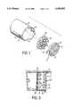
- FIG. 1is an exploded view of an improved receptacle for light emitting diodes
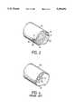
- FIG. 2is an assembled view of FIG. 1;
- FIG. 3is a cross-sectional view of the receptacle apparatus of FIG. 2 taken from lines 3--3;
- FIG. 4is a conventional receptacle for light emitting diodes.
- a receptacle for light emitting diodes in accordance with the present inventioncomprises the conventional receptacle of FIG. 4 and a light-resistant device 4. Similar to the conventional one, the receptacle of the present invention comprises a barrel-type housing 10 defining an opening 15 at one end and having a bottom at another end, a circuit board 30 from which a plurality of light emitting diodes 70 extend being adapted to be received in substantially a middle inner periphery of the barrel-type housing 10. The light emitting diodes 70 are secured to the circuit board 30 by soldering two pins thereto (see FIG. 3). A hole 12 is defined in the periphery of the barrel-type housing 10.
- a water outlet 13is defined adjacent to the hole 12 allowing water such as rain water to exit therethrough.
- a ridge 11is longitudinally formed along an inner periphery of the barrel-type housing 10.
- a stop 110is formed beside the ridge 11 substantially in a same longitudinal level with the hole 12.
- the circuit board 30defines a cut out (see dotted lines) preventing it from being obstructed by the ridge 11 and the stop 110 when it is placed in the barrel-type housing 10.
- the light-resistant device 4is a ring frame across which a plurality of louvers 43 are connected.
- a groove 41is defined at an outer periphery of the ring frame 40.
- a snapping member 42is formed on the outer periphery of the ring frame 40 diametrically opposite to the groove 41. Also referring to FIG.
- the circuit board 30is positioned in substantially a middle portion of the barrel 10.
- the ridge 11is used to guide the groove 41 of the ring frame 40 when the latter is positioned into the housing 10.
- the light-resistant device 4is positioned at substantially the opening 15 of the housing 10, with the groove 41 of the light-resistant device 4 receiving the ridge 11 of the housing 10 and the snapping member 42 of the light-resistant device 4 being retained in the hole 12, a portion of the outer periphery defining the groove 41 abutting against the stop 110 of the housing 10. With the light-resistant device 4, sunlight and/or other external light are restricted from entering the housing 10 to diminish illumination from the light emitting diodes 70.
Landscapes
- Engineering & Computer Science (AREA)
- General Engineering & Computer Science (AREA)
- Physics & Mathematics (AREA)
- General Physics & Mathematics (AREA)
- Theoretical Computer Science (AREA)
- Led Device Packages (AREA)
Abstract
Description
1. Field of the Invention
The present invention relates to a receptacle apparatus for light emitting diodes, especially one which provides a louvered effect to restrict external light such as sun light from entering therein thus increasing illumination from the light emitting diodes.
2. Description of the Prior Art
LED-type displaying boards are commonly used in the advertising field and each LED-type displaying board comprises a plurality of receptacles each of which comprises a plurality of LEDs installed thereon. FIG. 4 illustrates a conventional LED receptacle which includes a barrel-type housing 50 defining anopening 51 at one end and having a bottom at another end, acircuit board 30 adapted to be received in substantially a middle inner periphery of the barrel-type housing 50, a plurality ofLEDs 70 fixed on thecircuit board 30. This LED-type displaying board illuminates in a very satisfactory manner if it is positioned in a very dark area. However, if the LED-type displaying board is positioned in a very well-lit background such as outdoors and on a sunny day or in a scoring board where strong illuminating projecting lights are around, the light from theLEDs 70 is relatively weakened, thus reducing the displaying effect. Although the barrel-type housing contributes some light-resistant effect, external light such as sunlight still can project into the housing and strongly decrease the illumination effect from the LEDs. It is requisite to provide a new receptacle for preventing external light from entering the barrel-type housing yet allowing light from the light emitting diodes to emit therethrough.
The primary objective of the present invention is to provide a receptacle apparatus for light emitting diodes, which can prevent external light from decreasing the illumination effect from the light emitting diodes.
In accordance with one aspect of the invention, there is provided a receptacle for light emitting diodes comprising a barrel-type housing defining an opening at one end and shaving a bottom at another end; a circuit board from which a plurality of light emitting diodes extend being adapted to be received in substantially a middle inner periphery of the barrel-type housing; a hole being defined in a periphery of the barrel-type housing; a ridge being longitudinally formed along an inner periphery of the barrel-type housing; a stop being formed beside the ridge substantially in a same longitudinal level with the hole; a light-resistant device including a ring frame across which a plurality of louvers are connected, a groove defined at an outer periphery of the ring frame, a snapping member being formed on the outer periphery of the ring frame diametrically opposite to the groove; whereby the light-resistant device is positioned at substantially the opening of the housing, with the groove of the light-resistant device receiving the ridge of the housing and the snapping member of the light-resistant device being retained in the hole, a portion of the outer periphery defining the groove abutting against the stop of the barrel-type housing.
FIG. 1 is an exploded view of an improved receptacle for light emitting diodes;
FIG. 2 is an assembled view of FIG. 1;
FIG. 3 is a cross-sectional view of the receptacle apparatus of FIG. 2 taken from lines 3--3; and
FIG. 4 is a conventional receptacle for light emitting diodes.
Referring to the drawings and initially to FIG. 1, a receptacle for light emitting diodes in accordance with the present invention comprises the conventional receptacle of FIG. 4 and a light-resistant device 4. Similar to the conventional one, the receptacle of the present invention comprises a barrel-type housing 10 defining anopening 15 at one end and having a bottom at another end, acircuit board 30 from which a plurality oflight emitting diodes 70 extend being adapted to be received in substantially a middle inner periphery of the barrel-type housing 10. Thelight emitting diodes 70 are secured to thecircuit board 30 by soldering two pins thereto (see FIG. 3). Ahole 12 is defined in the periphery of the barrel-type housing 10. Awater outlet 13 is defined adjacent to thehole 12 allowing water such as rain water to exit therethrough. Aridge 11 is longitudinally formed along an inner periphery of the barrel-type housing 10. Astop 110 is formed beside theridge 11 substantially in a same longitudinal level with thehole 12. Thecircuit board 30 defines a cut out (see dotted lines) preventing it from being obstructed by theridge 11 and thestop 110 when it is placed in the barrel-type housing 10. The light-resistant device 4 is a ring frame across which a plurality oflouvers 43 are connected. Agroove 41 is defined at an outer periphery of thering frame 40. Asnapping member 42 is formed on the outer periphery of thering frame 40 diametrically opposite to thegroove 41. Also referring to FIG. 3, thecircuit board 30 is positioned in substantially a middle portion of thebarrel 10. Also referring to FIG. 2, theridge 11 is used to guide thegroove 41 of thering frame 40 when the latter is positioned into thehousing 10. The light-resistant device 4 is positioned at substantially the opening 15 of thehousing 10, with thegroove 41 of the light-resistant device 4 receiving theridge 11 of thehousing 10 and thesnapping member 42 of the light-resistant device 4 being retained in thehole 12, a portion of the outer periphery defining thegroove 41 abutting against thestop 110 of thehousing 10. With the light-resistant device 4, sunlight and/or other external light are restricted from entering thehousing 10 to diminish illumination from thelight emitting diodes 70.
Claims (2)
1. A receptacle for light emitting diodes comprising
a housing defining an opening at one end and having a bottom at another end;
a circuit board from which a plurality of light emitting diodes extend being adapted to be received in substantially a middle inner periphery of the housing;
a hole being defined in a periphery of the housing;
a ridge being longitudinally formed along an inner periphery of the housing;
a stop being formed beside the ridge substantially in a same longitudinal level with the hole;
a light-resistant device including a ring frame across which a plurality of louvers are connected, a groove defined at an outer periphery of the ring frame, a snapping member being formed on the outer periphery of the ring frame diametrically opposite to the groove;
whereby the light-resistant device is positioned at substantially the opening of the housing, with the groove of the light-resistant device receiving the ridge of the housing and the snapping member of the light-resistant device being retained in the hole, a portion of the outer periphery defining the groove abutting against the stop of the housing.
2. A receptacle for light emitting diodes as claimed in claim 1 further comprising a water outlet adjacent to the hole allowing water to exit therethrough.
Priority Applications (1)
| Application Number | Priority Date | Filing Date | Title |
|---|---|---|---|
| US08/252,360US5390092A (en) | 1994-06-01 | 1994-06-01 | Receptacle apparatus for light emitting diodes |
Applications Claiming Priority (1)
| Application Number | Priority Date | Filing Date | Title |
|---|---|---|---|
| US08/252,360US5390092A (en) | 1994-06-01 | 1994-06-01 | Receptacle apparatus for light emitting diodes |
Publications (1)
| Publication Number | Publication Date |
|---|---|
| US5390092Atrue US5390092A (en) | 1995-02-14 |
Family
ID=22955698
Family Applications (1)
| Application Number | Title | Priority Date | Filing Date |
|---|---|---|---|
| US08/252,360Expired - Fee RelatedUS5390092A (en) | 1994-06-01 | 1994-06-01 | Receptacle apparatus for light emitting diodes |
Country Status (1)
| Country | Link |
|---|---|
| US (1) | US5390092A (en) |
Cited By (32)
| Publication number | Priority date | Publication date | Assignee | Title |
|---|---|---|---|---|
| US5577832A (en)* | 1995-01-26 | 1996-11-26 | Lodhie; Pervaiz | Multilayer led assembly |
| US5658071A (en)* | 1995-12-12 | 1997-08-19 | Cooper Industries, Inc. | Lighting system including adjustable louver |
| EP0858064A1 (en)* | 1997-02-11 | 1998-08-12 | Signature SA | Sub-assembly for illuminated display and illuminated display screen using a juxtaposition of such sub-assemblies |
| US5808592A (en)* | 1994-04-28 | 1998-09-15 | Toyoda Gosei Co., Ltd. | Integrated light-emitting diode lamp and method of producing the same |
| USD402772S (en) | 1997-12-01 | 1998-12-15 | Ledtronics, Inc. | Illuminator |
| USD405426S (en) | 1997-02-07 | 1999-02-09 | Sanyo Electric Co., Ltd | Light emitting diode display |
| US6161910A (en)* | 1999-12-14 | 2000-12-19 | Aerospace Lighting Corporation | LED reading light |
| US6663269B1 (en)* | 2002-07-17 | 2003-12-16 | Poli-Auto, Inc. | Lighted exhaust pipe extension |
| US6739733B1 (en) | 2000-03-09 | 2004-05-25 | N.I.R., Inc. | LED lamp assembly |
| US20040218389A1 (en)* | 2000-03-09 | 2004-11-04 | Lamke Isidore I. | LED lamp assembly |
| US20040264206A1 (en)* | 2003-06-24 | 2004-12-30 | Miller William H. | LED sign cover and method of manufacture |
| US20040262472A1 (en)* | 2003-06-30 | 2004-12-30 | James Thomas | Angled mounting assembly for an LED cluster |
| US20050045175A1 (en)* | 2003-09-02 | 2005-03-03 | Mccawley Michael | Apparatus and method for delivery of an aerosol |
| EP1586814A3 (en)* | 2004-04-16 | 2006-06-07 | TRILUX-LENZE GmbH + Co. KG | Lighting system |
| US20070107281A1 (en)* | 2005-11-15 | 2007-05-17 | Skyline Products, Inc. | Hooded face plate for a message and display sign |
| US20070121325A1 (en)* | 2005-11-30 | 2007-05-31 | Benjamin Barber | Light directing louver |
| USD580580S1 (en) | 2008-01-11 | 2008-11-11 | Pervaiz Lodhie | Circular light structure |
| US20080278943A1 (en)* | 2005-11-11 | 2008-11-13 | Koninklijke Philips Electronics, N.V. | Luminaire Comprising Leds |
| US20090109674A1 (en)* | 2007-10-25 | 2009-04-30 | Pervaiz Lodhie | Led light |
| US20090109676A1 (en)* | 2007-10-30 | 2009-04-30 | Pervaiz Lodhie | Loop led light |
| USD613885S1 (en) | 2008-06-10 | 2010-04-13 | Pervaiz Lodhie | Two-stage LED light module |
| USD613886S1 (en) | 2008-06-10 | 2010-04-13 | Pervaiz Lodhie | LED light module with cutouts |
| USD614318S1 (en) | 2008-06-10 | 2010-04-20 | Pervaiz Lodhie | LED light module |
| US20100238671A1 (en)* | 2009-03-18 | 2010-09-23 | Koninklijke Philips Electronics N.V. | Led luminaire |
| US20110013397A1 (en)* | 2009-03-18 | 2011-01-20 | Koninklijke Philips Electronics N.V. | Led luminaire |
| USD631567S1 (en) | 2008-01-11 | 2011-01-25 | Pervaiz Lodhie | LED bulb |
| US20110128741A1 (en)* | 2009-11-30 | 2011-06-02 | Ge Investment Co., Ltd. | Lighting apparatus |
| US20110141728A1 (en)* | 2009-12-11 | 2011-06-16 | Koninklijke Philips Electronics N.V. | Lens frame with a led support surface and heat dissipating structure |
| US8123378B1 (en) | 2009-05-15 | 2012-02-28 | Koninklijke Philips Electronics N.V. | Heatsink for cooling at least one LED |
| US20150043220A1 (en)* | 2012-02-16 | 2015-02-12 | Koninklijke Philips N.V. | Using micro optical elements for depth perception in luminescent figurative structures illuminated by point sources |
| US10393363B2 (en) | 2017-04-25 | 2019-08-27 | Delta Faucet Company | Illumination device for a fluid delivery apparatus |
| EP4455553A1 (en)* | 2023-04-24 | 2024-10-30 | ZG Lighting France S.A.S | Lighting arrangement |
Citations (8)
| Publication number | Priority date | Publication date | Assignee | Title |
|---|---|---|---|---|
| US2530361A (en)* | 1948-02-03 | 1950-11-14 | Display Lighting Inc | Light baffle and support therefor |
| US2540389A (en)* | 1946-02-21 | 1951-02-06 | Elwood Wiles | Signal light ray director |
| US2701298A (en)* | 1952-05-14 | 1955-02-01 | Nicholas M Michailovsky | Driving light shield |
| US3446955A (en)* | 1966-04-29 | 1969-05-27 | Rotaflex Ltd | Lamp housing |
| US3987295A (en)* | 1975-10-21 | 1976-10-19 | Lawrence Peska Associates, Inc. | Automatically cleaned traffic light |
| US5023763A (en)* | 1988-10-21 | 1991-06-11 | Societe D'etudes Pour Le Developpement Des Productions Electroniques | Illuminated display panel |
| US5036248A (en)* | 1989-03-31 | 1991-07-30 | Ledstar Inc. | Light emitting diode clusters for display signs |
| US5268828A (en)* | 1991-04-19 | 1993-12-07 | Takiron Co., Ltd. | Illuminant display device |
- 1994
- 1994-06-01USUS08/252,360patent/US5390092A/ennot_activeExpired - Fee Related
Patent Citations (8)
| Publication number | Priority date | Publication date | Assignee | Title |
|---|---|---|---|---|
| US2540389A (en)* | 1946-02-21 | 1951-02-06 | Elwood Wiles | Signal light ray director |
| US2530361A (en)* | 1948-02-03 | 1950-11-14 | Display Lighting Inc | Light baffle and support therefor |
| US2701298A (en)* | 1952-05-14 | 1955-02-01 | Nicholas M Michailovsky | Driving light shield |
| US3446955A (en)* | 1966-04-29 | 1969-05-27 | Rotaflex Ltd | Lamp housing |
| US3987295A (en)* | 1975-10-21 | 1976-10-19 | Lawrence Peska Associates, Inc. | Automatically cleaned traffic light |
| US5023763A (en)* | 1988-10-21 | 1991-06-11 | Societe D'etudes Pour Le Developpement Des Productions Electroniques | Illuminated display panel |
| US5036248A (en)* | 1989-03-31 | 1991-07-30 | Ledstar Inc. | Light emitting diode clusters for display signs |
| US5268828A (en)* | 1991-04-19 | 1993-12-07 | Takiron Co., Ltd. | Illuminant display device |
Cited By (56)
| Publication number | Priority date | Publication date | Assignee | Title |
|---|---|---|---|---|
| US5808592A (en)* | 1994-04-28 | 1998-09-15 | Toyoda Gosei Co., Ltd. | Integrated light-emitting diode lamp and method of producing the same |
| US5577832A (en)* | 1995-01-26 | 1996-11-26 | Lodhie; Pervaiz | Multilayer led assembly |
| US5658071A (en)* | 1995-12-12 | 1997-08-19 | Cooper Industries, Inc. | Lighting system including adjustable louver |
| USD405426S (en) | 1997-02-07 | 1999-02-09 | Sanyo Electric Co., Ltd | Light emitting diode display |
| FR2759476A1 (en)* | 1997-02-11 | 1998-08-14 | Signature Sa | LUMINOUS DISPLAY SUB-ASSEMBLY AND LUMINOUS DISPLAY SCREEN CONSTITUTED BY JUXTAPOSITION OF SUCH SUB-ASSEMBLIES |
| EP0858064A1 (en)* | 1997-02-11 | 1998-08-12 | Signature SA | Sub-assembly for illuminated display and illuminated display screen using a juxtaposition of such sub-assemblies |
| USD402772S (en) | 1997-12-01 | 1998-12-15 | Ledtronics, Inc. | Illuminator |
| US6161910A (en)* | 1999-12-14 | 2000-12-19 | Aerospace Lighting Corporation | LED reading light |
| US7040779B2 (en) | 2000-03-09 | 2006-05-09 | Mongo Light Co. Inc | LED lamp assembly |
| US6739733B1 (en) | 2000-03-09 | 2004-05-25 | N.I.R., Inc. | LED lamp assembly |
| US20040174705A1 (en)* | 2000-03-09 | 2004-09-09 | Lamke Isidore I. | LED lamp assembly |
| US20040218389A1 (en)* | 2000-03-09 | 2004-11-04 | Lamke Isidore I. | LED lamp assembly |
| US7172315B2 (en) | 2000-03-09 | 2007-02-06 | Mongo Light Co., Inc. | LED lamp assembly |
| US6663269B1 (en)* | 2002-07-17 | 2003-12-16 | Poli-Auto, Inc. | Lighted exhaust pipe extension |
| US20040264206A1 (en)* | 2003-06-24 | 2004-12-30 | Miller William H. | LED sign cover and method of manufacture |
| US7287878B2 (en)* | 2003-06-24 | 2007-10-30 | Digital Recorders, Inc. | LED sign cover and method of manufacture |
| US20040262472A1 (en)* | 2003-06-30 | 2004-12-30 | James Thomas | Angled mounting assembly for an LED cluster |
| US20050045175A1 (en)* | 2003-09-02 | 2005-03-03 | Mccawley Michael | Apparatus and method for delivery of an aerosol |
| EP1586814A3 (en)* | 2004-04-16 | 2006-06-07 | TRILUX-LENZE GmbH + Co. KG | Lighting system |
| US20080278943A1 (en)* | 2005-11-11 | 2008-11-13 | Koninklijke Philips Electronics, N.V. | Luminaire Comprising Leds |
| US7520636B2 (en)* | 2005-11-11 | 2009-04-21 | Koninklijke Philips Electronics N.V. | Luminaire comprising LEDs |
| US20070107281A1 (en)* | 2005-11-15 | 2007-05-17 | Skyline Products, Inc. | Hooded face plate for a message and display sign |
| US7556403B2 (en)* | 2005-11-15 | 2009-07-07 | Skyline Products, Inc. | Hooded face plate for a message and display sign |
| US20070121325A1 (en)* | 2005-11-30 | 2007-05-31 | Benjamin Barber | Light directing louver |
| US20110128736A1 (en)* | 2007-10-25 | 2011-06-02 | Pervaiz Lodhie | LED Light |
| US7862204B2 (en) | 2007-10-25 | 2011-01-04 | Pervaiz Lodhie | LED light |
| US8157416B2 (en) | 2007-10-25 | 2012-04-17 | Pervaiz Lodhie | LED light |
| US20090109674A1 (en)* | 2007-10-25 | 2009-04-30 | Pervaiz Lodhie | Led light |
| US8128258B2 (en) | 2007-10-25 | 2012-03-06 | Pervaiz Lodhie | LED light |
| US20110122622A1 (en)* | 2007-10-25 | 2011-05-26 | Pervaiz Lodhie | LED Light |
| US7784967B2 (en) | 2007-10-30 | 2010-08-31 | Pervaiz Lodhie | Loop LED light |
| US20110002121A1 (en)* | 2007-10-30 | 2011-01-06 | Pervaiz Lodhie | Loop LED Light |
| US20090109676A1 (en)* | 2007-10-30 | 2009-04-30 | Pervaiz Lodhie | Loop led light |
| USD580580S1 (en) | 2008-01-11 | 2008-11-11 | Pervaiz Lodhie | Circular light structure |
| USD631567S1 (en) | 2008-01-11 | 2011-01-25 | Pervaiz Lodhie | LED bulb |
| USD595886S1 (en) | 2008-01-11 | 2009-07-07 | Pervaiz Lodhie | Circular light structure |
| USD599496S1 (en) | 2008-01-11 | 2009-09-01 | Pervaiz Lodhie | Circular light structure |
| USD613885S1 (en) | 2008-06-10 | 2010-04-13 | Pervaiz Lodhie | Two-stage LED light module |
| USD629957S1 (en) | 2008-06-10 | 2010-12-28 | Pervaiz Lodhie | LED light module |
| USD630372S1 (en) | 2008-06-10 | 2011-01-04 | Pervaiz Lodhie | Two-stage LED light module |
| USD613886S1 (en) | 2008-06-10 | 2010-04-13 | Pervaiz Lodhie | LED light module with cutouts |
| USD631601S1 (en) | 2008-06-10 | 2011-01-25 | Pervaiz Lodhie | LED light module with cutouts |
| USD614318S1 (en) | 2008-06-10 | 2010-04-20 | Pervaiz Lodhie | LED light module |
| US8414155B2 (en) | 2009-03-18 | 2013-04-09 | Koninklijke Philips Electronics N.V. | LED luminaire |
| US20100238671A1 (en)* | 2009-03-18 | 2010-09-23 | Koninklijke Philips Electronics N.V. | Led luminaire |
| US8376582B2 (en) | 2009-03-18 | 2013-02-19 | Koninklijke Philips Electronics N.V. | LED luminaire |
| US20110013397A1 (en)* | 2009-03-18 | 2011-01-20 | Koninklijke Philips Electronics N.V. | Led luminaire |
| US8123378B1 (en) | 2009-05-15 | 2012-02-28 | Koninklijke Philips Electronics N.V. | Heatsink for cooling at least one LED |
| US8292461B2 (en) | 2009-05-15 | 2012-10-23 | Koninklijke Philips Electronics N.V. | Heatsink for cooling at least one LED |
| US20110128741A1 (en)* | 2009-11-30 | 2011-06-02 | Ge Investment Co., Ltd. | Lighting apparatus |
| US20110141728A1 (en)* | 2009-12-11 | 2011-06-16 | Koninklijke Philips Electronics N.V. | Lens frame with a led support surface and heat dissipating structure |
| US8506127B2 (en) | 2009-12-11 | 2013-08-13 | Koninklijke Philips N.V. | Lens frame with a LED support surface and heat dissipating structure |
| US20150043220A1 (en)* | 2012-02-16 | 2015-02-12 | Koninklijke Philips N.V. | Using micro optical elements for depth perception in luminescent figurative structures illuminated by point sources |
| US10393363B2 (en) | 2017-04-25 | 2019-08-27 | Delta Faucet Company | Illumination device for a fluid delivery apparatus |
| US10697628B2 (en) | 2017-04-25 | 2020-06-30 | Delta Faucet Company | Faucet illumination device |
| EP4455553A1 (en)* | 2023-04-24 | 2024-10-30 | ZG Lighting France S.A.S | Lighting arrangement |
Similar Documents
| Publication | Publication Date | Title |
|---|---|---|
| US5390092A (en) | Receptacle apparatus for light emitting diodes | |
| US7033037B2 (en) | Dazzling light device | |
| US6851832B2 (en) | Led tube light housings | |
| DE60130546T2 (en) | OPTIMIZED SYMBOLOGY LIGHTING DEVICE AND METHOD | |
| US6076940A (en) | Planter light accessory | |
| WO2003066374A3 (en) | Center high mounted stop lamp including leds and tir lens | |
| US6942354B2 (en) | Lighting system and housing therefore | |
| DE102005028694B4 (en) | Device for illuminating a target surface of a vehicle, in particular a license plate | |
| DE112011101270T5 (en) | Low profile extrusion | |
| US5584565A (en) | Tool with workpiece illumination | |
| EP1495910B1 (en) | Lighting element with an illumination means | |
| US10890468B2 (en) | Light ring assembly and method of using the same | |
| EP1498656A3 (en) | Lighting device, in particular tunnel lighting | |
| US20040090777A1 (en) | LED flashlight assembly | |
| DE102021133846A1 (en) | LIGHTING DEVICE | |
| AU3946499A (en) | Warning light with light emitting diodes | |
| USD369573S (en) | Shaped plaque with light emitting diode chaser circuit | |
| EP0976971A3 (en) | Light emitting device, in particular lamp or lantern | |
| DE50005822D1 (en) | EXTERNAL REAR VIEW MIRROR FOR A VEHICLE WITH A LIGHTING DEVICE | |
| US20080239713A1 (en) | Solar door lighting system | |
| DE10147288A1 (en) | Illumination for vehicle trunk has at least one LED light source instead of incandescent lamp; white light emitting LED or combination of LEDs emitting different colors can be used | |
| JP2935677B2 (en) | Rail decoration of pachinko machine | |
| JP4488610B2 (en) | Construction safety light | |
| GB2340301A (en) | Side illuminating light emitting diode | |
| GB2404435A (en) | Illumination decoration for skateboard |
Legal Events
| Date | Code | Title | Description |
|---|---|---|---|
| AS | Assignment | Owner name:FORMOSA INDUSTRIAL COMPUTING INC., SWITZERLAND Free format text:ASSIGNMENT OF ASSIGNORS INTEREST;ASSIGNOR:LIN, SHARMING;REEL/FRAME:007024/0620 Effective date:19940526 | |
| FPAY | Fee payment | Year of fee payment:4 | |
| FPAY | Fee payment | Year of fee payment:8 | |
| REMI | Maintenance fee reminder mailed | ||
| LAPS | Lapse for failure to pay maintenance fees | ||
| STCH | Information on status: patent discontinuation | Free format text:PATENT EXPIRED DUE TO NONPAYMENT OF MAINTENANCE FEES UNDER 37 CFR 1.362 | |
| FP | Lapsed due to failure to pay maintenance fee | Effective date:20070214 |