US5390077A - Integrated circuit cooling device having internal baffle - Google Patents
Integrated circuit cooling device having internal baffleDownload PDFInfo
- Publication number
- US5390077A US5390077AUS08/274,937US27493794AUS5390077AUS 5390077 AUS5390077 AUS 5390077AUS 27493794 AUS27493794 AUS 27493794AUS 5390077 AUS5390077 AUS 5390077A
- Authority
- US
- United States
- Prior art keywords
- coolant
- pool
- baffle
- chamber
- orifice
- Prior art date
- Legal status (The legal status is an assumption and is not a legal conclusion. Google has not performed a legal analysis and makes no representation as to the accuracy of the status listed.)
- Expired - Lifetime
Links
Images


Classifications
- H—ELECTRICITY
- H01—ELECTRIC ELEMENTS
- H01L—SEMICONDUCTOR DEVICES NOT COVERED BY CLASS H10
- H01L23/00—Details of semiconductor or other solid state devices
- H01L23/34—Arrangements for cooling, heating, ventilating or temperature compensation ; Temperature sensing arrangements
- H01L23/42—Fillings or auxiliary members in containers or encapsulations selected or arranged to facilitate heating or cooling
- H01L23/427—Cooling by change of state, e.g. use of heat pipes
- H—ELECTRICITY
- H01—ELECTRIC ELEMENTS
- H01L—SEMICONDUCTOR DEVICES NOT COVERED BY CLASS H10
- H01L23/00—Details of semiconductor or other solid state devices
- H01L23/34—Arrangements for cooling, heating, ventilating or temperature compensation ; Temperature sensing arrangements
- H01L23/40—Mountings or securing means for detachable cooling or heating arrangements ; fixed by friction, plugs or springs
- H01L23/4093—Snap-on arrangements, e.g. clips
- H—ELECTRICITY
- H01—ELECTRIC ELEMENTS
- H01L—SEMICONDUCTOR DEVICES NOT COVERED BY CLASS H10
- H01L2924/00—Indexing scheme for arrangements or methods for connecting or disconnecting semiconductor or solid-state bodies as covered by H01L24/00
- H01L2924/0001—Technical content checked by a classifier
- H01L2924/0002—Not covered by any one of groups H01L24/00, H01L24/00 and H01L2224/00
- H—ELECTRICITY
- H01—ELECTRIC ELEMENTS
- H01L—SEMICONDUCTOR DEVICES NOT COVERED BY CLASS H10
- H01L2924/00—Indexing scheme for arrangements or methods for connecting or disconnecting semiconductor or solid-state bodies as covered by H01L24/00
- H01L2924/30—Technical effects
- H01L2924/301—Electrical effects
- H01L2924/3011—Impedance
- Y—GENERAL TAGGING OF NEW TECHNOLOGICAL DEVELOPMENTS; GENERAL TAGGING OF CROSS-SECTIONAL TECHNOLOGIES SPANNING OVER SEVERAL SECTIONS OF THE IPC; TECHNICAL SUBJECTS COVERED BY FORMER USPC CROSS-REFERENCE ART COLLECTIONS [XRACs] AND DIGESTS
- Y10—TECHNICAL SUBJECTS COVERED BY FORMER USPC
- Y10T—TECHNICAL SUBJECTS COVERED BY FORMER US CLASSIFICATION
- Y10T29/00—Metal working
- Y10T29/49—Method of mechanical manufacture
- Y10T29/4935—Heat exchanger or boiler making
- Y10T29/49353—Heat pipe device making
Definitions
- the present inventionrelates generally to dissipation of heat generated by electronic components, and more particularly to an apparatus for cooling an integrated circuit device.
- Cooling of certain integrated circuit devicesare necessary to ensure their proper operation and useful life. Also, cooling provides for enhanced performance of such integrated circuit devices.
- Such devicesinclude mechanisms which circulate coolants such as air, water and fluorocarbons through the housings in which they are contained.
- U.S. Pat. No. 4,572,286discloses a boiling cooling apparatus that includes a heat generating device which is completely immersed in a liquid coolant which partially fills a sealed container. At least one vertically extending passage is provided through the heat producing device whereby ascending bubbles formed in the passage by the heat transfer from the heat generating device to the liquid medium cause an upward current flow through the passage.
- a plurality of current flow control platesare provided for diverting the upward flow of liquid coolant laterally and downwardly along the sides of the container to provide convection cooling and directing the downward flow of the liquid coolant into the lower end of the passage in the heat generating device to provide a cyclic flow of the cooling liquid.
- U.S. Pat. No. 4,698,728which describes a liquid cooling system that includes a frame holding a plurality of printed circuit boards, each of which has electrical components attached thereto.
- the systemfurther includes a top reservoir for holding a liquid at atmospheric pressure, a conduit for conveying the liquid in a downward direction from the top reservoir over the components, a bottom reservoir for receiving the liquid plus any air due to leaks from the conduit, a pump for sucking the liquid and air through the conduit at subatmospheric pressures and for returning the liquid to the top reservoir.
- U.S. Pat. No. 5,216,580discloses an optimized integral heat pipe and electronic circuit module arrangement.
- a ceramic multi-chip module bearing electronic circuit componentshas applied to the side opposite the electronic circuit components preparatory metallization and a thermal wick.
- a heat pipe evaporator chamber and condenser assemblyis attached to the multi-chip module and wick assembly.
- a suitable working fluidis introduced into the vapor chamber and the vapor chamber hermetically sealed.
- Application of the thermal wick to the heat producing multi-chip moduleeliminates the thermal impedance contributed by the thermal transmission media, permitting a doubling of heat flux from the multi-chip module to the heat pipe evaporator.
- Some prior art devicesmay allow areas of the liquid coolant contained in the cooling device housing to stagnate thereby reducing the effectiveness of the heat transfer process. This is especially true for passive devices that cool integrated circuit chips (i.e. devices which do not utilize an electric pump or motor to circulate the coolant through the housing). Also, some prior art devices are relatively inefficient at transferring heat away from the integrated circuit device due to their overall configuration and design.
- an apparatus for cooling an integrated circuit deviceincludes a container defining a chamber that is partially filled with a coolant which forms a coolant pool in the chamber, wherein heat generated by the integrated circuit device causes boiling of the coolant at a heating area of the coolant pool so that vaporized coolant rises upwardly from the coolant pool and condenses on a ceiling of the chamber forming coolant droplets thereon.
- the apparatusfurther includes a baffle positioned within the chamber and at least partially out of the coolant pool, the baffle further being positioned within a path traveled by the coolant droplets falling from the ceiling due to gravity, wherein the baffle is configured to guide the coolant droplets away from the heating area of the coolant pool as the coolant droplets fall from the ceiling towards the coolant pool due to gravity.
- a method of cooling an integrated circuit deviceincludes the steps of (1) providing a container which defines a chamber; (2) partially filling the container with a coolant so as to form a coolant pool in the chamber; (3) generating heat by the integrated circuit device so as to boil the coolant at a heating area of the coolant pool so that vaporized coolant rises upwardly from the coolant pool and condenses on a ceiling of the chamber forming coolant droplets thereon; (4) positioning a baffle (a) within the chamber, (b) at least partially out of the coolant pool, and (c) within a path defined by the coolant droplets falling from the ceiling due to gravity; and (5) guiding coolant droplets away from the heating area of the coolant pool with the baffle as the coolant droplets fall from the ceiling due to gravity.
- FIG. 1is a sectional view taken in the direction of the arrows 1--1 of FIG. 3 showing an apparatus for cooling an integrated circuit device that incorporates the features of the present invention therein;
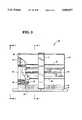
- FIG. 2is a side elevational view of the apparatus for cooling an integrated circuit device taken in the direction of the arrows 2--2 of FIG. 3;
- FIG. 3is a front elevational view of the apparatus for cooling an integrated circuit device of FIG. 1, with a portion of the container of the apparatus shown removed for clarity of description.
- FIGS. 1-3there is shown an apparatus 40 for cooling an integrated circuit 42 such as a Pentium integrated circuit device available from Intel Corporation of Santa Clara, Calif.
- an integrated circuit 42such as a Pentium integrated circuit device available from Intel Corporation of Santa Clara, Calif.
- a chip socket 43is secured to a printed circuit board 45 as shown in FIGS. 1-3.
- the printed circuit board 45has positioned thereon numerous electrical circuits (not shown).
- the integrated circuit device 42is plugged into the chip socket 43 so as to connect the integrated circuit device to the electrical circuits on the printed circuit board.
- the chip socket 43includes a pair of clips 47 which secure the cooling apparatus 40 at a location adjacent to the integrated circuit device 42.
- the cooling apparatus 40is positioned in contact with the integrated circuit device 42 as shown in FIGS. 1-3. Since the bottom of the cooling device and the top of the integrated circuit device 42 may each be microscopically uneven so that these two surfaces are not positioned entirely flush against each other, a conductive paste is interposed between these two surfaces to enhance heat transfer.
- a conductive paste which may be usedis a metal oxide filled, silicone-free synthetic grease.
- one metal oxide filled, silicone-free synthetic grease which may be usedis Sil-Free 1020, a trademark of Aavid Engineering, Inc. of Laconia, N.H.
- the cooling apparatus 40includes a container 44 defining a chamber 46.
- the container 44is extruded from an aluminum material.
- the container 44has a plurality of fins 48 extending therefrom.
- the chamber 46is partially filled with a coolant 50 which forms a coolant pool 52 in the chamber as shown in FIG. 1.
- the coolant 50is a non-electrically conductive liquid.
- the coolant 50may be a non-electrically conductive fluorinated liquid such as Fluourinert, a trademark of Minnesota Mining and Manufacturing Company of St. Paul, Minn. If the cooling apparatus 40 were to crack thereby leaking the coolant 50 onto the printed circuit board, the circuits on the printed circuit board would not be short circuited since the coolant 50 is non-electrically conductive.
- the integrated circuit device 42produces heat which causes boiling of the coolant 50 at a heating area 51 in the coolant pool 52.
- the heating area 51 of the coolant pool 52is defined by the area of the coolant pool which has the highest temperature within the coolant pool.
- the heating area 51 of the coolant pool 52would be an area of the coolant pool which is closest in distance to the integrated circuit device 42 as shown in FIG. 1.
- vaporized coolantAs the coolant 50 boils, vaporized coolant, schematically shown as arrows 53 in FIG. 1, rises upwardly from the coolant pool towards a ceiling of the chamber 46. Upon reaching the ceiling of the chamber, the vaporized coolant 53 condenses thus forming coolant droplets 55 thereon. Thereafter, the coolant droplets 55 fall downwardly from the ceiling due to gravity.
- the cooling apparatus 40further includes a cooling conduit 54 positioned within the chamber 16.
- the cooling conduit 54includes a first conduit segment 60 and a second conduit segment 62.
- the conduit segments 60 and 62are positioned partially out of the coolant pool 52 as shown in FIG. 1.
- the conduit segments 60 and 62are positioned in a first path traveled by the vaporized coolant 53 as it rises upwardly from the coolant pool towards the ceiling.
- coolant dropletsform on the conduit segments 60 and 62 as the vaporized coolant travels upwardly in the chamber 46.
- the conduit segments 60 and 62are positioned in a second path traveled by the coolant droplets 55 as they fall downwardly from the ceiling due to gravity.
- Each of the conduit segments 60 and 62is extruded into an elongated member having a central channel extending therethrough. Each of the conduit segments has an orifice on each side of thereof.
- the conduit segments 60 and 62are extruded from an aluminum material. As configured, each of the conduit segments 60 and 62 defines a passageway though which ambient air (from outside the chamber 46) may pass.
- the cooling apparatus 40further includes a first end cap 58 (see FIGS. 2 and 3) and a second end cap (not shown) which is friction fit between the container 44 and the cooling segments 60 and 62.
- a glueis applied between each end cap and the container 44, and each end cap and the conduit segments 60 and 62 so as to provide a liquid tight seal.
- the first and second end capssupport the conduit segments 60 and 62 within the cooling apparatus 40.
- the first and second end capsare stamped into shape from an aluminum material.
- Each of the end capshas two openings defined therein. When the end caps are secured to the conduit segments 60 and 62, the two openings of each end cap aligns with two respective orifices of the two conduit segments.
- alignis that an opening of an end cap and an orifice of a conduit segment overlaps (i.e. aligns) to some extent so as to allow a fluid, such as air, to advance through the opening and the orifice when the end cap is secured to the conduit segment. (See e.g. FIG. 3 which partially shows the alignment of one opening of end cap 58 with an orifice of conduit segment 62.)
- the coolant dropletsthen run downwardly over the surface of the conduit segments 60 and 62 until they eventually enter the coolant pool 52 at a return area 57 of the coolant pool as shown in FIG. 1. It is important to note that the return area 57 of the coolant pool is remote from the heating area 51 of the coolant pool. It is further important to note that each of the conduit segments 60 and 62 functions as a baffle to guide the coolant droplets 55 away from the heating area 51 of the coolant pool 52 as the coolant droplets fall from the ceiling toward the coolant pool due to gravity.
- the integrated circuit device 42As heat is generated by the integrated circuit device 42, it is transferred to the base of the container 44 and then to the coolant 50 in the coolant pool 52. As the coolant 50 boils, the vaporized coolant 53 rises upwardly in the container so as to contact the conduit segments 60 and 62. Some of the heat is then transferred to the conduit segments and then to the ambient air which is located within the passageways of the conduit segments 60 and 62. As ambient air advances through the conduit segments, the heat moves out of the passageways and is thereafter dissipated into the ambient surroundings.
- the coolant droplets 55As the coolant droplets 55 form on the ceiling of the chamber 46, they begin to drop downwardly due to gravity thereby contacting the conduit segments 60 and 62. The coolant droplets then run downwardly over the surface of the conduit segments 60 and 62. Some of the heat contained in these coolant droplets is transferred to the conduit segments and then to the ambient surroundings as described above. Thereafter, the coolant droplets enter the coolant pool 52 at the return area 57 as shown in FIG. 1. The above-described cycle is then repeated so as to further cool the integrated circuit device 42.
Landscapes
- Physics & Mathematics (AREA)
- Condensed Matter Physics & Semiconductors (AREA)
- General Physics & Mathematics (AREA)
- Engineering & Computer Science (AREA)
- Computer Hardware Design (AREA)
- Microelectronics & Electronic Packaging (AREA)
- Power Engineering (AREA)
- Cooling Or The Like Of Semiconductors Or Solid State Devices (AREA)
Abstract
Description
Cross reference is made to co-pending U.S. patent application Ser. No. 08/274,947, entitled "Cooling Device for an Integrated Circuit having Internal Cooling Conduit" by Robert W. Paterson which is assigned to the same assignee as the present invention, and filed concurrently herewith.
The present invention relates generally to dissipation of heat generated by electronic components, and more particularly to an apparatus for cooling an integrated circuit device.
Cooling of certain integrated circuit devices are necessary to ensure their proper operation and useful life. Also, cooling provides for enhanced performance of such integrated circuit devices.
Various designs for apparatus which cool integrated circuit devices have been developed. Such devices include mechanisms which circulate coolants such as air, water and fluorocarbons through the housings in which they are contained.
One example of such a design is U.S. Pat. No. 4,572,286 which discloses a boiling cooling apparatus that includes a heat generating device which is completely immersed in a liquid coolant which partially fills a sealed container. At least one vertically extending passage is provided through the heat producing device whereby ascending bubbles formed in the passage by the heat transfer from the heat generating device to the liquid medium cause an upward current flow through the passage. A plurality of current flow control plates are provided for diverting the upward flow of liquid coolant laterally and downwardly along the sides of the container to provide convection cooling and directing the downward flow of the liquid coolant into the lower end of the passage in the heat generating device to provide a cyclic flow of the cooling liquid.
Another example is U.S. Pat. No. 4,698,728 which describes a liquid cooling system that includes a frame holding a plurality of printed circuit boards, each of which has electrical components attached thereto. The system further includes a top reservoir for holding a liquid at atmospheric pressure, a conduit for conveying the liquid in a downward direction from the top reservoir over the components, a bottom reservoir for receiving the liquid plus any air due to leaks from the conduit, a pump for sucking the liquid and air through the conduit at subatmospheric pressures and for returning the liquid to the top reservoir.
Yet another example is U.S. Pat. No. 5,216,580 which discloses an optimized integral heat pipe and electronic circuit module arrangement. A ceramic multi-chip module bearing electronic circuit components has applied to the side opposite the electronic circuit components preparatory metallization and a thermal wick. A heat pipe evaporator chamber and condenser assembly is attached to the multi-chip module and wick assembly. A suitable working fluid is introduced into the vapor chamber and the vapor chamber hermetically sealed. Application of the thermal wick to the heat producing multi-chip module eliminates the thermal impedance contributed by the thermal transmission media, permitting a doubling of heat flux from the multi-chip module to the heat pipe evaporator.
Some prior art devices may allow areas of the liquid coolant contained in the cooling device housing to stagnate thereby reducing the effectiveness of the heat transfer process. This is especially true for passive devices that cool integrated circuit chips (i.e. devices which do not utilize an electric pump or motor to circulate the coolant through the housing). Also, some prior art devices are relatively inefficient at transferring heat away from the integrated circuit device due to their overall configuration and design.
It would be desirable to provide an apparatus for cooling an integrated circuit device that is passive (i.e. no electric pump or motor) and which does not allow significant stagnation of the liquid coolant in the cooling device housing. It would also be desirable to provide an apparatus for cooling an integrated circuit device that efficiently transfers heat away from the integrated circuit device. It would further be desirable if such cooling apparatus was easy to assemble and inexpensive to manufacture.
In accordance with one embodiment of the present invention, there is provided an apparatus for cooling an integrated circuit device. The apparatus includes a container defining a chamber that is partially filled with a coolant which forms a coolant pool in the chamber, wherein heat generated by the integrated circuit device causes boiling of the coolant at a heating area of the coolant pool so that vaporized coolant rises upwardly from the coolant pool and condenses on a ceiling of the chamber forming coolant droplets thereon. The apparatus further includes a baffle positioned within the chamber and at least partially out of the coolant pool, the baffle further being positioned within a path traveled by the coolant droplets falling from the ceiling due to gravity, wherein the baffle is configured to guide the coolant droplets away from the heating area of the coolant pool as the coolant droplets fall from the ceiling towards the coolant pool due to gravity.
Pursuant to another embodiment of the present invention, there is provided a method of cooling an integrated circuit device. The method includes the steps of (1) providing a container which defines a chamber; (2) partially filling the container with a coolant so as to form a coolant pool in the chamber; (3) generating heat by the integrated circuit device so as to boil the coolant at a heating area of the coolant pool so that vaporized coolant rises upwardly from the coolant pool and condenses on a ceiling of the chamber forming coolant droplets thereon; (4) positioning a baffle (a) within the chamber, (b) at least partially out of the coolant pool, and (c) within a path defined by the coolant droplets falling from the ceiling due to gravity; and (5) guiding coolant droplets away from the heating area of the coolant pool with the baffle as the coolant droplets fall from the ceiling due to gravity.
It is therefore an object of the present invention to provide a new and useful apparatus for cooling an integrated circuit device.
It is a further object of the present invention to provide an improved apparatus for cooling an integrated circuit device.
It is another object of the present invention to provide a new and useful method of cooling an integrated circuit device.
It is moreover an object of the present invention to provide an improved method of cooling an integrated circuit device.
It is still another object of the present invention to provide an apparatus for cooling an integrated circuit device which is relatively efficient at transferring heat away from the integrated circuit device.
It is moreover another object of the present invention to provide a method for cooling an integrated circuit device which is relatively efficient at transferring heat away from the integrated circuit device.
It is yet another object of the present invention to provide an apparatus for cooling an integrated circuit device that is passive (i.e. no electric motor or pump) and which reduces stagnation of the liquid coolant contained in the cooling device housing.
It is still another object of the present invention to provide a method of cooling an integrated circuit device which reduces stagnation of the liquid coolant contained in the cooling device housing without the use of electric pumps or motors.
The above and other objects, features, and advantages of the present invention will become apparent from the following description and the attached drawings.
FIG. 1 is a sectional view taken in the direction of thearrows 1--1 of FIG. 3 showing an apparatus for cooling an integrated circuit device that incorporates the features of the present invention therein;
FIG. 2 is a side elevational view of the apparatus for cooling an integrated circuit device taken in the direction of thearrows 2--2 of FIG. 3; and
FIG. 3 is a front elevational view of the apparatus for cooling an integrated circuit device of FIG. 1, with a portion of the container of the apparatus shown removed for clarity of description.
While the invention is susceptible to various modifications and alternative forms, a specific embodiment thereof has been shown by way of example in the drawings and will herein be described in detail. It should be understood, however, that there is no intent to limit the invention to the particular form disclosed, but on the contrary, the intention is to cover all modifications, equivalents, and alternatives falling within the spirit and scope of the invention as defined by the appended claims.
Referring now to FIGS. 1-3, there is shown anapparatus 40 for cooling an integratedcircuit 42 such as a Pentium integrated circuit device available from Intel Corporation of Santa Clara, Calif.
Achip socket 43 is secured to a printedcircuit board 45 as shown in FIGS. 1-3. The printedcircuit board 45 has positioned thereon numerous electrical circuits (not shown). Theintegrated circuit device 42 is plugged into thechip socket 43 so as to connect the integrated circuit device to the electrical circuits on the printed circuit board. Thechip socket 43 includes a pair ofclips 47 which secure thecooling apparatus 40 at a location adjacent to the integratedcircuit device 42.
Thecooling apparatus 40 is positioned in contact with the integratedcircuit device 42 as shown in FIGS. 1-3. Since the bottom of the cooling device and the top of the integratedcircuit device 42 may each be microscopically uneven so that these two surfaces are not positioned entirely flush against each other, a conductive paste is interposed between these two surfaces to enhance heat transfer. A conductive paste which may be used is a metal oxide filled, silicone-free synthetic grease. For example, one metal oxide filled, silicone-free synthetic grease which may be used is Sil-Free 1020, a trademark of Aavid Engineering, Inc. of Laconia, N.H.
Thecooling apparatus 40 includes acontainer 44 defining achamber 46. Thecontainer 44 is extruded from an aluminum material. Thecontainer 44 has a plurality offins 48 extending therefrom.
Thechamber 46 is partially filled with acoolant 50 which forms acoolant pool 52 in the chamber as shown in FIG. 1. Thecoolant 50 is a non-electrically conductive liquid. For example, thecoolant 50 may be a non-electrically conductive fluorinated liquid such as Fluourinert, a trademark of Minnesota Mining and Manufacturing Company of St. Paul, Minn. If thecooling apparatus 40 were to crack thereby leaking thecoolant 50 onto the printed circuit board, the circuits on the printed circuit board would not be short circuited since thecoolant 50 is non-electrically conductive.
During its operation, theintegrated circuit device 42 produces heat which causes boiling of thecoolant 50 at a heating area 51 in thecoolant pool 52. The heating area 51 of thecoolant pool 52 is defined by the area of the coolant pool which has the highest temperature within the coolant pool. In particular, the heating area 51 of thecoolant pool 52 would be an area of the coolant pool which is closest in distance to theintegrated circuit device 42 as shown in FIG. 1.
As thecoolant 50 boils, vaporized coolant, schematically shown asarrows 53 in FIG. 1, rises upwardly from the coolant pool towards a ceiling of thechamber 46. Upon reaching the ceiling of the chamber, the vaporizedcoolant 53 condenses thus formingcoolant droplets 55 thereon. Thereafter, thecoolant droplets 55 fall downwardly from the ceiling due to gravity.
Thecooling apparatus 40 further includes acooling conduit 54 positioned within the chamber 16. The coolingconduit 54 includes afirst conduit segment 60 and asecond conduit segment 62. Theconduit segments coolant pool 52 as shown in FIG. 1. Moreover, theconduit segments coolant 53 as it rises upwardly from the coolant pool towards the ceiling. As a result, coolant droplets form on theconduit segments chamber 46. In addition, theconduit segments coolant droplets 55 as they fall downwardly from the ceiling due to gravity.
Each of theconduit segments conduit segments conduit segments
Thecooling apparatus 40 further includes a first end cap 58 (see FIGS. 2 and 3) and a second end cap (not shown) which is friction fit between thecontainer 44 and the coolingsegments container 44, and each end cap and theconduit segments conduit segments cooling apparatus 40. The first and second end caps are stamped into shape from an aluminum material. Each of the end caps has two openings defined therein. When the end caps are secured to theconduit segments end cap 58 with an orifice ofconduit segment 62.)
During operation of theintegrated circuit device 42, heat is produced so that thecoolant 50 in thecoolant pool 52 boils. This causes vaporizedcoolant 53 to rise upwardly from the coolant pool and contact theconduit segments coolant 53 condenses on theconduit segments coolant 53 continues to rise until it reaches the ceiling of thechamber 46 thereby formingcoolant droplets 55 thereon. As thecoolant droplets 55 continue to form on the ceiling, they begin to fall downwardly onto theconduit segments conduit segments coolant pool 52 at a return area 57 of the coolant pool as shown in FIG. 1. It is important to note that the return area 57 of the coolant pool is remote from the heating area 51 of the coolant pool. It is further important to note that each of theconduit segments coolant droplets 55 away from the heating area 51 of thecoolant pool 52 as the coolant droplets fall from the ceiling toward the coolant pool due to gravity.
As heat is generated by theintegrated circuit device 42, it is transferred to the base of thecontainer 44 and then to thecoolant 50 in thecoolant pool 52. As thecoolant 50 boils, the vaporizedcoolant 53 rises upwardly in the container so as to contact theconduit segments conduit segments
As the remainder of thecoolant vapor 53 continues to rise, it eventually contacts the ceiling of thechamber 46. Some of the heat is then transferred through the wall of thecontainer 44 to the outside of thecooling apparatus 40 so as to be dissipated into the ambient surroundings.
As thecoolant droplets 55 form on the ceiling of thechamber 46, they begin to drop downwardly due to gravity thereby contacting theconduit segments conduit segments coolant pool 52 at the return area 57 as shown in FIG. 1. The above-described cycle is then repeated so as to further cool theintegrated circuit device 42.
While the invention has been illustrated and described in detail in the drawings and foregoing description, such illustration and description is to be considered as exemplary and not restrictive in character, it being understood that only the preferred embodiments have been shown and described and that all changes and modifications that come within the spirit of the invention are desired to be protected.
Claims (11)
1. An apparatus for cooling an integrated circuit device, comprising:
a container defining a chamber that is partially filled with a coolant which forms a coolant pool in the chamber, wherein heat generated by the integrated circuit device causes boiling of the coolant at a heating area of the coolant pool so that vaporized coolant rises upwardly from the coolant pool and condenses on a ceiling of the chamber forming coolant droplets thereon; and
a baffle positioned within the chamber and at least partially out of the coolant pool, said baffle further being positioned within a path traveled by the coolant droplets falling from the ceiling due to gravity, wherein said baffle is configured to guide the coolant droplets away from the heating area of the coolant pool as the coolant droplets fall from the ceiling towards the coolant pool due to gravity.
2. The apparatus of claim 1, wherein:
said container has a first opening and a second opening defined therein; and
said baffle is secured to said container and defines a conduit having a first orifice and a second orifice, wherein the first opening is aligned with the first orifice and the second opening is aligned with the second orifice,
wherein ambient air located outside of the chamber is able to pass through the conduit defined by said baffle.
3. The apparatus of claim 2, wherein said baffle is positioned in a path traveled by vaporized coolant rising from the coolant pool towards the ceiling.
4. The apparatus of claim 1, wherein said baffle includes:
a first baffle segment attached to said container; and
a second baffle segment attached to said container.
5. The apparatus of claim 4, wherein:
said container has defined therein a first opening, a second opening, a third opening, and a fourth opening;
said first baffle segment is secured to said container and defines a first conduit having a first orifice and a second orifice, wherein the first opening is aligned with the first orifice and the second opening is aligned with the second orifice; and
said second baffle segment is secured to said container and defines a second conduit having a third orifice and a fourth orifice, wherein the third opening is aligned with the third orifice and the fourth opening is aligned with the fourth orifice,
wherein ambient air located outside of the chamber is able to pass through the first baffle segment and the second baffle segment.
6. The apparatus of claim 5, wherein the first baffle segment and the second baffle segment are each positioned in the path traveled by vaporized coolant rising from the coolant pool towards the ceiling.
7. The apparatus of claim 1, wherein said baffle is configured to guide the coolant droplets to a return area of the coolant pool which is remote from the heating area of the coolant pool.
8. The apparatus of claim 1, wherein the coolant is a non-electrically conductive liquid.
9. A method of cooling an integrated circuit device, comprising the steps of:
providing a container which defines a chamber;
partially filling the container with a coolant so as to form a coolant pool in the chamber;
generating heat by the integrated circuit device so as to boil the coolant at a heating area of the coolant pool so that vaporized coolant rises upwardly from the coolant pool and condenses on a ceiling of the chamber forming coolant droplets thereon;
positioning a baffle (1) within the chamber, (2) at least partially out of the coolant pool, and (3) within a path defined by the coolant droplets falling from the ceiling due to gravity; and
guiding coolant droplets away from the heating area of the coolant pool with the baffle as the coolant droplets fall from the ceiling towards the coolant pool due to gravity.
10. The method of claim 9, wherein said guiding step further includes the step of guiding the coolant droplets with the baffle to a return area of the coolant pool which is remote from the heating area of the coolant pool.
11. The method of claim 1 0, further comprising the step of advancing coolant from the return area of the coolant pool to the heating area of the coolant pool.
Priority Applications (1)
| Application Number | Priority Date | Filing Date | Title |
|---|---|---|---|
| US08/274,937US5390077A (en) | 1994-07-14 | 1994-07-14 | Integrated circuit cooling device having internal baffle |
Applications Claiming Priority (1)
| Application Number | Priority Date | Filing Date | Title |
|---|---|---|---|
| US08/274,937US5390077A (en) | 1994-07-14 | 1994-07-14 | Integrated circuit cooling device having internal baffle |
Publications (1)
| Publication Number | Publication Date |
|---|---|
| US5390077Atrue US5390077A (en) | 1995-02-14 |
Family
ID=23050220
Family Applications (1)
| Application Number | Title | Priority Date | Filing Date |
|---|---|---|---|
| US08/274,937Expired - LifetimeUS5390077A (en) | 1994-07-14 | 1994-07-14 | Integrated circuit cooling device having internal baffle |
Country Status (1)
| Country | Link |
|---|---|
| US (1) | US5390077A (en) |
Cited By (54)
| Publication number | Priority date | Publication date | Assignee | Title |
|---|---|---|---|---|
| US5529115A (en)* | 1994-07-14 | 1996-06-25 | At&T Global Information Solutions Company | Integrated circuit cooling device having internal cooling conduit |
| EP0745819A3 (en)* | 1995-05-30 | 1997-11-05 | Fujikura Ltd. | Heat pipe and process for manufacturing the same |
| US5777852A (en)* | 1995-07-20 | 1998-07-07 | Bell; James S. | Clamping device for securing an electrical component to a circuit board |
| US5836381A (en)* | 1994-07-19 | 1998-11-17 | Nippondenso Co., Ltd. | Cooling apparatus using boiling and condensing refrigerant |
| US5864466A (en)* | 1994-07-19 | 1999-01-26 | Remsburg; Ralph | Thermosyphon-powered jet-impingement cooling device |
| US6064572A (en)* | 1996-11-27 | 2000-05-16 | Remsburg; Ralph | Thermosyphon-powered jet-impingement cooling device |
| US6144553A (en)* | 1998-09-09 | 2000-11-07 | Sun Microsystems, Inc. | Refrigeration cooled disk storage assembly |
| US6227287B1 (en)* | 1998-05-25 | 2001-05-08 | Denso Corporation | Cooling apparatus by boiling and cooling refrigerant |
| US6304447B1 (en) | 1998-12-31 | 2001-10-16 | Lucent Technologies, Inc. | Arrangement for cooling an electrical assembly |
| US6365260B1 (en)* | 1996-06-29 | 2002-04-02 | Robert Bosch Gmbh | Arrangement for heat dissipation in chip modules on multilayered ceramic carriers, in particular multichip modules |
| US6408937B1 (en) | 2000-11-15 | 2002-06-25 | Sanjay K. Roy | Active cold plate/heat sink |
| US6439298B1 (en)* | 2001-04-17 | 2002-08-27 | Jia Hao Li | Cylindrical heat radiator |
| US6457228B1 (en)* | 1999-06-14 | 2002-10-01 | Hitachi, Ltd. | Method for sealing liquid coolant into module |
| US6459581B1 (en)* | 2000-12-19 | 2002-10-01 | Harris Corporation | Electronic device using evaporative micro-cooling and associated methods |
| US20030034148A1 (en)* | 2001-08-16 | 2003-02-20 | Nec Corporation | Telecommunication device including a housing having improved heat conductivity |
| US6538883B1 (en)* | 2001-09-19 | 2003-03-25 | Turin Networks | Method and apparatus for thermally insulated and earth cooled electronic components within an electronic system |
| US6550531B1 (en)* | 2000-05-16 | 2003-04-22 | Intel Corporation | Vapor chamber active heat sink |
| US20030098588A1 (en)* | 2001-11-26 | 2003-05-29 | Kazuaki Yazawa | Method and apparatus for converting dissipated heat to work energy |
| US6625024B2 (en)* | 2001-07-06 | 2003-09-23 | Alstom | Power converter enclosure |
| US20030178184A1 (en)* | 2000-05-16 | 2003-09-25 | Kroliczek Edward J. | Wick having liquid superheat tolerance and being resistant to back-conduction, evaporator employing a liquid superheat tolerant wick, and loop heat pipe incorporating same |
| US6687124B2 (en)* | 2002-06-24 | 2004-02-03 | General Motors Corporation | Apparatus for cooling electronic components in a phase change electronic cooling system |
| US6820684B1 (en)* | 2003-06-26 | 2004-11-23 | International Business Machines Corporation | Cooling system and cooled electronics assembly employing partially liquid filled thermal spreader |
| US20040244951A1 (en)* | 1999-05-12 | 2004-12-09 | Dussinger Peter M. | Integrated circuit heat pipe heat spreader with through mounting holes |
| US6856510B2 (en) | 2001-03-26 | 2005-02-15 | Chi Mei Chang | Efficient cooler |
| US20050045309A1 (en)* | 2003-09-03 | 2005-03-03 | Yoshihiro Kondo | Electronic apparatus |
| US20050051307A1 (en)* | 1999-05-12 | 2005-03-10 | Dussinger Peter M. | Integrated circuit heat pipe heat spreader with through mounting holes |
| US20060144565A1 (en)* | 2004-12-30 | 2006-07-06 | Delta Electronics, Inc. | Heat dissipation devices and fabrication methods thereof |
| WO2007015696A1 (en)* | 2005-08-01 | 2007-02-08 | Mohammed Alam | Self-actuating and regulating heat exchange system |
| US20080041565A1 (en)* | 2006-08-16 | 2008-02-21 | Hon Hai Precision Industry Co., Ltd. | Integrated cooling system with multiple condensing passages for cooling electronic components |
| US20080236795A1 (en)* | 2007-03-26 | 2008-10-02 | Seung Mun You | Low-profile heat-spreading liquid chamber using boiling |
| JP2008294294A (en)* | 2007-05-25 | 2008-12-04 | Toyota Motor Corp | Cooling device |
| US20090002947A1 (en)* | 2007-04-13 | 2009-01-01 | Xcelaero Corporation | Evaporative cooling system for electronic components |
| CN100495691C (en)* | 2005-01-31 | 2009-06-03 | 杨开艳 | A kind of CPU cooler |
| US20090242174A1 (en)* | 2008-03-31 | 2009-10-01 | Mccutchen Co. | Vapor vortex heat sink |
| US20110277475A1 (en)* | 2010-05-11 | 2011-11-17 | Dell Products L.P. | Power regeneration for an information handling system |
| US20110315343A1 (en)* | 2010-06-29 | 2011-12-29 | International Business Machines Corporation | Interleaved, immersion-cooling apparatuses and methods for cooling electronic subsystems |
| US20110315344A1 (en)* | 2010-06-29 | 2011-12-29 | International Business Machines Corporation | Interleaved, immersion-cooling apparatus and method for an electronic subsystem of an electronics rack |
| US20120120604A1 (en)* | 2010-11-11 | 2012-05-17 | Mingliang Hao | Heat dissipation device |
| US20120268877A1 (en)* | 2011-04-25 | 2012-10-25 | Jeremy Rice | Thermosiphon Systems for Electronic Devices |
| US8351206B2 (en) | 2010-06-29 | 2013-01-08 | International Business Machines Corporation | Liquid-cooled electronics rack with immersion-cooled electronic subsystems and vertically-mounted, vapor-condensing unit |
| US20140068942A1 (en)* | 2012-09-13 | 2014-03-13 | International Business Machines Corporation | Vapor condenser with three-dimensional folded structure |
| US20140182132A1 (en)* | 2013-01-01 | 2014-07-03 | Asia Vital Components Co., Ltd. | Method of manufacturing a vapor chamber structure |
| EP2733569A3 (en)* | 2012-11-19 | 2014-10-01 | Acer Incorporated | Fluid heat exchange apparatus |
| US20140321053A1 (en)* | 2013-04-29 | 2014-10-30 | Brian G. Donnelly | Temperature Regulation Via Immersion In A Liquid |
| US20150144315A1 (en)* | 2013-11-27 | 2015-05-28 | Subtron Technology Co., Ltd. | Heat dissipation substrate |
| CN105283038A (en)* | 2014-07-22 | 2016-01-27 | 西门子公司 | Cooling device for cooling electronic and/or electric element in targeted manner |
| US9500413B1 (en) | 2012-06-14 | 2016-11-22 | Google Inc. | Thermosiphon systems with nested tubes |
| US9835383B1 (en) | 2013-03-15 | 2017-12-05 | Hrl Laboratories, Llc | Planar heat pipe with architected core and vapor tolerant arterial wick |
| US11121125B2 (en)* | 2018-12-12 | 2021-09-14 | Micron Technology, Inc. | Thermal chamber for a thermal control component |
| US11334129B2 (en) | 2019-12-11 | 2022-05-17 | Micron Technology, Inc. | Temperature control component for electronic systems |
| US11444004B2 (en)* | 2019-04-05 | 2022-09-13 | Fuji Electric Co., Ltd. | Cooler |
| US11493550B2 (en) | 2019-12-11 | 2022-11-08 | Micron Technology, Inc. | Standalone thermal chamber for a temperature control component |
| USD995530S1 (en) | 2018-12-12 | 2023-08-15 | Micron Technology, Inc. | Thermal control component |
| US20230389242A1 (en)* | 2022-05-31 | 2023-11-30 | GE Grid GmbH | Hybrid thermosyphon with immersion cooled evaporator |
Citations (15)
| Publication number | Priority date | Publication date | Assignee | Title |
|---|---|---|---|---|
| JPS57204156A (en)* | 1981-06-09 | 1982-12-14 | Mitsubishi Electric Corp | Ebullition type cooling device |
| US4519447A (en)* | 1980-08-04 | 1985-05-28 | Fine Particle Technology Corporation | Substrate cooling |
| US4572286A (en)* | 1981-04-07 | 1986-02-25 | Mitsubishi Denki Kabushiki Kaisha | Boiling cooling apparatus |
| US4698728A (en)* | 1986-10-14 | 1987-10-06 | Unisys Corporation | Leak tolerant liquid cooling system |
| US4750086A (en)* | 1985-12-11 | 1988-06-07 | Unisys Corporation | Apparatus for cooling integrated circuit chips with forced coolant jet |
| US4799543A (en)* | 1987-11-12 | 1989-01-24 | Arthur H. Iversen | Means for temperature control of heated surfaces |
| US4823863A (en)* | 1986-03-20 | 1989-04-25 | Hitachi, Ltd. | Thermal conduction device |
| US4866570A (en)* | 1988-08-05 | 1989-09-12 | Ncr Corporation | Apparatus and method for cooling an electronic device |
| US4870477A (en)* | 1986-05-23 | 1989-09-26 | Hitachi, Ltd. | Integrated circuit chips cooling module having coolant leakage prevention device |
| US4920574A (en)* | 1985-10-04 | 1990-04-24 | Fujitsu Limited | Cooling system for an electronic circuit device |
| US4928206A (en)* | 1988-11-23 | 1990-05-22 | Ncr Corporation | Foldable printed circuit board |
| US5000256A (en)* | 1990-07-20 | 1991-03-19 | Minnesota Mining And Manufacturing Company | Heat transfer bag with thermal via |
| US5212626A (en)* | 1990-11-09 | 1993-05-18 | International Business Machines Corporation | Electronic packaging and cooling system using superconductors for power distribution |
| US5216580A (en)* | 1992-01-14 | 1993-06-01 | Sun Microsystems, Inc. | Optimized integral heat pipe and electronic circuit module arrangement |
| US5263536A (en)* | 1991-07-19 | 1993-11-23 | Thermo Electron Technologies Corp. | Miniature heat exchanger |
- 1994
- 1994-07-14USUS08/274,937patent/US5390077A/ennot_activeExpired - Lifetime
Patent Citations (16)
| Publication number | Priority date | Publication date | Assignee | Title |
|---|---|---|---|---|
| US4519447A (en)* | 1980-08-04 | 1985-05-28 | Fine Particle Technology Corporation | Substrate cooling |
| US4572286A (en)* | 1981-04-07 | 1986-02-25 | Mitsubishi Denki Kabushiki Kaisha | Boiling cooling apparatus |
| US4653579A (en)* | 1981-04-07 | 1987-03-31 | Mitsubishi Denki Kabushiki Kaisha | Boiling cooling apparatus |
| JPS57204156A (en)* | 1981-06-09 | 1982-12-14 | Mitsubishi Electric Corp | Ebullition type cooling device |
| US4920574A (en)* | 1985-10-04 | 1990-04-24 | Fujitsu Limited | Cooling system for an electronic circuit device |
| US4750086A (en)* | 1985-12-11 | 1988-06-07 | Unisys Corporation | Apparatus for cooling integrated circuit chips with forced coolant jet |
| US4823863A (en)* | 1986-03-20 | 1989-04-25 | Hitachi, Ltd. | Thermal conduction device |
| US4870477A (en)* | 1986-05-23 | 1989-09-26 | Hitachi, Ltd. | Integrated circuit chips cooling module having coolant leakage prevention device |
| US4698728A (en)* | 1986-10-14 | 1987-10-06 | Unisys Corporation | Leak tolerant liquid cooling system |
| US4799543A (en)* | 1987-11-12 | 1989-01-24 | Arthur H. Iversen | Means for temperature control of heated surfaces |
| US4866570A (en)* | 1988-08-05 | 1989-09-12 | Ncr Corporation | Apparatus and method for cooling an electronic device |
| US4928206A (en)* | 1988-11-23 | 1990-05-22 | Ncr Corporation | Foldable printed circuit board |
| US5000256A (en)* | 1990-07-20 | 1991-03-19 | Minnesota Mining And Manufacturing Company | Heat transfer bag with thermal via |
| US5212626A (en)* | 1990-11-09 | 1993-05-18 | International Business Machines Corporation | Electronic packaging and cooling system using superconductors for power distribution |
| US5263536A (en)* | 1991-07-19 | 1993-11-23 | Thermo Electron Technologies Corp. | Miniature heat exchanger |
| US5216580A (en)* | 1992-01-14 | 1993-06-01 | Sun Microsystems, Inc. | Optimized integral heat pipe and electronic circuit module arrangement |
Cited By (91)
| Publication number | Priority date | Publication date | Assignee | Title |
|---|---|---|---|---|
| US5529115A (en)* | 1994-07-14 | 1996-06-25 | At&T Global Information Solutions Company | Integrated circuit cooling device having internal cooling conduit |
| US5836381A (en)* | 1994-07-19 | 1998-11-17 | Nippondenso Co., Ltd. | Cooling apparatus using boiling and condensing refrigerant |
| US5864466A (en)* | 1994-07-19 | 1999-01-26 | Remsburg; Ralph | Thermosyphon-powered jet-impingement cooling device |
| EP0745819A3 (en)* | 1995-05-30 | 1997-11-05 | Fujikura Ltd. | Heat pipe and process for manufacturing the same |
| US5694295A (en)* | 1995-05-30 | 1997-12-02 | Fujikura Ltd. | Heat pipe and process for manufacturing the same |
| US5777852A (en)* | 1995-07-20 | 1998-07-07 | Bell; James S. | Clamping device for securing an electrical component to a circuit board |
| US6365260B1 (en)* | 1996-06-29 | 2002-04-02 | Robert Bosch Gmbh | Arrangement for heat dissipation in chip modules on multilayered ceramic carriers, in particular multichip modules |
| US6064572A (en)* | 1996-11-27 | 2000-05-16 | Remsburg; Ralph | Thermosyphon-powered jet-impingement cooling device |
| US6227287B1 (en)* | 1998-05-25 | 2001-05-08 | Denso Corporation | Cooling apparatus by boiling and cooling refrigerant |
| US6144553A (en)* | 1998-09-09 | 2000-11-07 | Sun Microsystems, Inc. | Refrigeration cooled disk storage assembly |
| US6304447B1 (en) | 1998-12-31 | 2001-10-16 | Lucent Technologies, Inc. | Arrangement for cooling an electrical assembly |
| US7066240B2 (en) | 1999-05-12 | 2006-06-27 | Thermal Corp | Integrated circuit heat pipe heat spreader with through mounting holes |
| US7100680B2 (en) | 1999-05-12 | 2006-09-05 | Thermal Corp. | Integrated circuit heat pipe heat spreader with through mounting holes |
| US20060243425A1 (en)* | 1999-05-12 | 2006-11-02 | Thermal Corp. | Integrated circuit heat pipe heat spreader with through mounting holes |
| US7100679B2 (en) | 1999-05-12 | 2006-09-05 | Thermal Corp. | Integrated circuit heat pipe heat spreader with through mounting holes |
| US7028760B2 (en) | 1999-05-12 | 2006-04-18 | Thermal Corp. | Integrated circuit heat pipe heat spreader with through mounting holes |
| US20060032615A1 (en)* | 1999-05-12 | 2006-02-16 | Dussinger Peter M | Integrated circuit heat pipe heat spreader with through mounting holes |
| US20050145374A1 (en)* | 1999-05-12 | 2005-07-07 | Dussinger Peter M. | Integrated circuit heat pipe heat spreader with through mounting holes |
| US6896039B2 (en) | 1999-05-12 | 2005-05-24 | Thermal Corp. | Integrated circuit heat pipe heat spreader with through mounting holes |
| US20050051307A1 (en)* | 1999-05-12 | 2005-03-10 | Dussinger Peter M. | Integrated circuit heat pipe heat spreader with through mounting holes |
| US20040244951A1 (en)* | 1999-05-12 | 2004-12-09 | Dussinger Peter M. | Integrated circuit heat pipe heat spreader with through mounting holes |
| US6457228B1 (en)* | 1999-06-14 | 2002-10-01 | Hitachi, Ltd. | Method for sealing liquid coolant into module |
| US20030178184A1 (en)* | 2000-05-16 | 2003-09-25 | Kroliczek Edward J. | Wick having liquid superheat tolerance and being resistant to back-conduction, evaporator employing a liquid superheat tolerant wick, and loop heat pipe incorporating same |
| US9103602B2 (en) | 2000-05-16 | 2015-08-11 | Orbital Atk, Inc. | Evaporators including a capillary wick and a plurality of vapor grooves and two-phase heat transfer systems including such evaporators |
| US8397798B2 (en) | 2000-05-16 | 2013-03-19 | Alliant Techsystems Inc. | Evaporators including a capillary wick and a plurality of vapor grooves and two-phase heat transfer systems including such evaporators |
| US6550531B1 (en)* | 2000-05-16 | 2003-04-22 | Intel Corporation | Vapor chamber active heat sink |
| US6915843B2 (en)* | 2000-05-16 | 2005-07-12 | Swales & Associates, Inc. | Wick having liquid superheat tolerance and being resistant to back-conduction, evaporator employing a liquid superheat tolerant wick, and loop heat pipe incorporating same |
| US20050252643A1 (en)* | 2000-05-16 | 2005-11-17 | Swales & Associates, Inc. A Delaware Corporation | Wick having liquid superheat tolerance and being resistant to back-conduction, evaporator employing a liquid superheat tolerant wick, and loop heat pipe incorporating same |
| US6408937B1 (en) | 2000-11-15 | 2002-06-25 | Sanjay K. Roy | Active cold plate/heat sink |
| US6459581B1 (en)* | 2000-12-19 | 2002-10-01 | Harris Corporation | Electronic device using evaporative micro-cooling and associated methods |
| US6856510B2 (en) | 2001-03-26 | 2005-02-15 | Chi Mei Chang | Efficient cooler |
| US6439298B1 (en)* | 2001-04-17 | 2002-08-27 | Jia Hao Li | Cylindrical heat radiator |
| US6625024B2 (en)* | 2001-07-06 | 2003-09-23 | Alstom | Power converter enclosure |
| US7040383B2 (en)* | 2001-08-16 | 2006-05-09 | Nec Corporation | Telecommunication device including a housing having improved heat conductivity |
| US20030034148A1 (en)* | 2001-08-16 | 2003-02-20 | Nec Corporation | Telecommunication device including a housing having improved heat conductivity |
| US6538883B1 (en)* | 2001-09-19 | 2003-03-25 | Turin Networks | Method and apparatus for thermally insulated and earth cooled electronic components within an electronic system |
| US6804114B1 (en) | 2001-09-19 | 2004-10-12 | Turin Networks | Method and apparatus for thermally insulated and earth cooled electronic components within an electronic system |
| US20030098588A1 (en)* | 2001-11-26 | 2003-05-29 | Kazuaki Yazawa | Method and apparatus for converting dissipated heat to work energy |
| US6856037B2 (en)* | 2001-11-26 | 2005-02-15 | Sony Corporation | Method and apparatus for converting dissipated heat to work energy |
| US6687124B2 (en)* | 2002-06-24 | 2004-02-03 | General Motors Corporation | Apparatus for cooling electronic components in a phase change electronic cooling system |
| US6820684B1 (en)* | 2003-06-26 | 2004-11-23 | International Business Machines Corporation | Cooling system and cooled electronics assembly employing partially liquid filled thermal spreader |
| US20050045309A1 (en)* | 2003-09-03 | 2005-03-03 | Yoshihiro Kondo | Electronic apparatus |
| US20060144565A1 (en)* | 2004-12-30 | 2006-07-06 | Delta Electronics, Inc. | Heat dissipation devices and fabrication methods thereof |
| CN100495691C (en)* | 2005-01-31 | 2009-06-03 | 杨开艳 | A kind of CPU cooler |
| WO2007015696A1 (en)* | 2005-08-01 | 2007-02-08 | Mohammed Alam | Self-actuating and regulating heat exchange system |
| US7661465B2 (en)* | 2006-08-16 | 2010-02-16 | Hon Hai Precision Industry Co., Ltd. | Integrated cooling system with multiple condensing passages for cooling electronic components |
| US20080041565A1 (en)* | 2006-08-16 | 2008-02-21 | Hon Hai Precision Industry Co., Ltd. | Integrated cooling system with multiple condensing passages for cooling electronic components |
| US20080236795A1 (en)* | 2007-03-26 | 2008-10-02 | Seung Mun You | Low-profile heat-spreading liquid chamber using boiling |
| US20090002947A1 (en)* | 2007-04-13 | 2009-01-01 | Xcelaero Corporation | Evaporative cooling system for electronic components |
| US20100155027A1 (en)* | 2007-05-25 | 2010-06-24 | Toyota Jodosha Kabushiki Kaisha | Cooling device |
| JP2008294294A (en)* | 2007-05-25 | 2008-12-04 | Toyota Motor Corp | Cooling device |
| DE112008001282B4 (en)* | 2007-05-25 | 2013-04-18 | Toyota Jidosha Kabushiki Kaisha | cooler |
| US7980078B2 (en) | 2008-03-31 | 2011-07-19 | Mccutchen Co. | Vapor vortex heat sink |
| US20110232875A1 (en)* | 2008-03-31 | 2011-09-29 | Mccutchen Co. | Vapor vortex heat sink |
| US8739540B2 (en) | 2008-03-31 | 2014-06-03 | Mccutchen Co. | Vapor vortex heat sink |
| US20090242174A1 (en)* | 2008-03-31 | 2009-10-01 | Mccutchen Co. | Vapor vortex heat sink |
| US20110277475A1 (en)* | 2010-05-11 | 2011-11-17 | Dell Products L.P. | Power regeneration for an information handling system |
| US8850816B2 (en)* | 2010-05-11 | 2014-10-07 | Dell Products L.P. | Power regeneration for an information handling system |
| US8369091B2 (en)* | 2010-06-29 | 2013-02-05 | International Business Machines Corporation | Interleaved, immersion-cooling apparatus and method for an electronic subsystem of an electronics rack |
| US8345423B2 (en)* | 2010-06-29 | 2013-01-01 | International Business Machines Corporation | Interleaved, immersion-cooling apparatuses and methods for cooling electronic subsystems |
| US8351206B2 (en) | 2010-06-29 | 2013-01-08 | International Business Machines Corporation | Liquid-cooled electronics rack with immersion-cooled electronic subsystems and vertically-mounted, vapor-condensing unit |
| US20110315343A1 (en)* | 2010-06-29 | 2011-12-29 | International Business Machines Corporation | Interleaved, immersion-cooling apparatuses and methods for cooling electronic subsystems |
| US20110315344A1 (en)* | 2010-06-29 | 2011-12-29 | International Business Machines Corporation | Interleaved, immersion-cooling apparatus and method for an electronic subsystem of an electronics rack |
| US8737071B2 (en)* | 2010-11-11 | 2014-05-27 | Huawei Technologies Co., Ltd. | Heat dissipation device |
| US20120120604A1 (en)* | 2010-11-11 | 2012-05-17 | Mingliang Hao | Heat dissipation device |
| US20120268877A1 (en)* | 2011-04-25 | 2012-10-25 | Jeremy Rice | Thermosiphon Systems for Electronic Devices |
| US10225959B2 (en) | 2011-04-25 | 2019-03-05 | Google Llc | Thermosiphon systems for electronic devices |
| US8773854B2 (en)* | 2011-04-25 | 2014-07-08 | Google Inc. | Thermosiphon systems for electronic devices |
| US9521786B2 (en) | 2011-04-25 | 2016-12-13 | Google Inc. | Thermosiphon systems for electronic devices |
| US9500413B1 (en) | 2012-06-14 | 2016-11-22 | Google Inc. | Thermosiphon systems with nested tubes |
| US9713291B1 (en) | 2012-06-14 | 2017-07-18 | Google Inc. | Thermosiphon systems with nested tubes |
| US20140068942A1 (en)* | 2012-09-13 | 2014-03-13 | International Business Machines Corporation | Vapor condenser with three-dimensional folded structure |
| US8941994B2 (en) | 2012-09-13 | 2015-01-27 | International Business Machines Corporation | Vapor condenser with three-dimensional folded structure |
| US8739406B2 (en)* | 2012-09-13 | 2014-06-03 | International Business Machines Corporation | Vapor condenser with three-dimensional folded structure |
| US9423189B2 (en) | 2012-11-19 | 2016-08-23 | Acer Incorporated | Fluid heat exchange apparatus |
| EP2733569A3 (en)* | 2012-11-19 | 2014-10-01 | Acer Incorporated | Fluid heat exchange apparatus |
| US20140182132A1 (en)* | 2013-01-01 | 2014-07-03 | Asia Vital Components Co., Ltd. | Method of manufacturing a vapor chamber structure |
| US9835383B1 (en) | 2013-03-15 | 2017-12-05 | Hrl Laboratories, Llc | Planar heat pipe with architected core and vapor tolerant arterial wick |
| US20140321053A1 (en)* | 2013-04-29 | 2014-10-30 | Brian G. Donnelly | Temperature Regulation Via Immersion In A Liquid |
| US20150144315A1 (en)* | 2013-11-27 | 2015-05-28 | Subtron Technology Co., Ltd. | Heat dissipation substrate |
| CN105283038A (en)* | 2014-07-22 | 2016-01-27 | 西门子公司 | Cooling device for cooling electronic and/or electric element in targeted manner |
| US11658175B2 (en) | 2018-12-12 | 2023-05-23 | Micron Technology, Inc. | Thermal chamber for a thermal control component |
| US11121125B2 (en)* | 2018-12-12 | 2021-09-14 | Micron Technology, Inc. | Thermal chamber for a thermal control component |
| USD995530S1 (en) | 2018-12-12 | 2023-08-15 | Micron Technology, Inc. | Thermal control component |
| US11444004B2 (en)* | 2019-04-05 | 2022-09-13 | Fuji Electric Co., Ltd. | Cooler |
| US11493550B2 (en) | 2019-12-11 | 2022-11-08 | Micron Technology, Inc. | Standalone thermal chamber for a temperature control component |
| US11334129B2 (en) | 2019-12-11 | 2022-05-17 | Micron Technology, Inc. | Temperature control component for electronic systems |
| US11808803B2 (en) | 2019-12-11 | 2023-11-07 | Micron Technology, Inc. | Standalone thermal chamber for a temperature control component |
| US12181940B2 (en) | 2019-12-11 | 2024-12-31 | Micron Technology, Inc. | Temperature control component for electronic systems wherein a thermal transfer component is tappered |
| US20230389242A1 (en)* | 2022-05-31 | 2023-11-30 | GE Grid GmbH | Hybrid thermosyphon with immersion cooled evaporator |
| US11943904B2 (en)* | 2022-05-31 | 2024-03-26 | GE Grid GmbH | Hybrid thermosyphon with immersion cooled evaporator |
Similar Documents
| Publication | Publication Date | Title |
|---|---|---|
| US5390077A (en) | Integrated circuit cooling device having internal baffle | |
| US5529115A (en) | Integrated circuit cooling device having internal cooling conduit | |
| US6490160B2 (en) | Vapor chamber with integrated pin array | |
| US6324058B1 (en) | Heat-dissipating apparatus for an integrated circuit device | |
| KR100238769B1 (en) | Heat pipe | |
| US7770630B2 (en) | Modular capillary pumped loop cooling system | |
| US6863118B1 (en) | Micro grooved heat pipe | |
| US4503483A (en) | Heat pipe cooling module for high power circuit boards | |
| JPH04233259A (en) | Removal device of heat | |
| KR930016751A (en) | Optimized heat pipe and electronics integrated assembly | |
| US7143815B2 (en) | Liquid cooling device | |
| US20060096743A1 (en) | Liquid cooling device | |
| US20050083655A1 (en) | Dielectric thermal stack for the cooling of high power electronics | |
| CN101170087A (en) | Power module having self-contained cooling system | |
| US6749013B2 (en) | Heat sink | |
| CA2440522A1 (en) | Electronic module including a cooling substrate and related methods | |
| CA2235620A1 (en) | Liquid cooled heat sink for cooling electronic components | |
| JP2007059917A (en) | Combined heat dissipation device | |
| CN113811069B (en) | Cooling device and method for manufacturing same | |
| CN219677255U (en) | Electronic component integrating three-dimensional vapor cavity and liquid cooling heat dissipation | |
| US20020189791A1 (en) | Liquid circulation cooler | |
| US20030235036A1 (en) | Apparatus for cooling electronic components in a phase change electronic cooling system | |
| US20160095254A1 (en) | Managing heat transfer for electronic devices | |
| US20190339021A1 (en) | Joint vapor chamber assembly with vapor chambers connected by extension wick layer | |
| US4805691A (en) | Cooling technique for compact electronics inverter |
Legal Events
| Date | Code | Title | Description |
|---|---|---|---|
| AS | Assignment | Owner name:AT&T GLOBAL INFORMATION SOLUTIONS COMPANY LAW D Free format text:ASSIGNMENT OF ASSIGNORS INTEREST;ASSIGNOR:PATERSON, ROBERT W.;REEL/FRAME:007076/0995 Effective date:19940706 | |
| STCF | Information on status: patent grant | Free format text:PATENTED CASE | |
| AS | Assignment | Owner name:NCR CORPORATION, OHIO Free format text:ASSIGNMENT OF ASSIGNORS INTEREST;ASSIGNOR:AT&T GLOBAL INFORMATION SOLUTIONS COMPANY;REEL/FRAME:008047/0429 Effective date:19960109 | |
| FEPP | Fee payment procedure | Free format text:PAYOR NUMBER ASSIGNED (ORIGINAL EVENT CODE: ASPN); ENTITY STATUS OF PATENT OWNER: LARGE ENTITY | |
| FPAY | Fee payment | Year of fee payment:4 | |
| FPAY | Fee payment | Year of fee payment:8 | |
| FPAY | Fee payment | Year of fee payment:12 | |
| AS | Assignment | Owner name:TERADATA US, INC., OHIO Free format text:ASSIGNMENT OF ASSIGNORS INTEREST;ASSIGNOR:NCR CORPORATION;REEL/FRAME:020540/0786 Effective date:20070924 |