US5389850A - Rotational shock sensor - Google Patents
Rotational shock sensorDownload PDFInfo
- Publication number
- US5389850A US5389850AUS08/191,988US19198894AUS5389850AUS 5389850 AUS5389850 AUS 5389850AUS 19198894 AUS19198894 AUS 19198894AUS 5389850 AUS5389850 AUS 5389850A
- Authority
- US
- United States
- Prior art keywords
- sensor
- flywheel
- voltage
- case
- attached
- Prior art date
- Legal status (The legal status is an assumption and is not a legal conclusion. Google has not performed a legal analysis and makes no representation as to the accuracy of the status listed.)
- Expired - Lifetime
Links
Images


Classifications
- G—PHYSICS
- G01—MEASURING; TESTING
- G01P—MEASURING LINEAR OR ANGULAR SPEED, ACCELERATION, DECELERATION, OR SHOCK; INDICATING PRESENCE, ABSENCE, OR DIRECTION, OF MOVEMENT
- G01P15/00—Measuring acceleration; Measuring deceleration; Measuring shock, i.e. sudden change of acceleration
- G01P15/02—Measuring acceleration; Measuring deceleration; Measuring shock, i.e. sudden change of acceleration by making use of inertia forces using solid seismic masses
- G01P15/08—Measuring acceleration; Measuring deceleration; Measuring shock, i.e. sudden change of acceleration by making use of inertia forces using solid seismic masses with conversion into electric or magnetic values
- G01P15/0888—Measuring acceleration; Measuring deceleration; Measuring shock, i.e. sudden change of acceleration by making use of inertia forces using solid seismic masses with conversion into electric or magnetic values for indicating angular acceleration
Definitions
- the inventionrelates generally to the field of motion sensors; more specifically, to apparatus for sensing rotational displacements in mobile computing devices, including portable data storage devices.
- an actuator armis employed to position one or more transducers over a concentric data track of the magnetic medium.
- these actuator assembliesare generally immune to sudden linear accelerations or shock displacements. They are, however, very sensitive to rotational displacements. For example, a rotational acceleration component in the plane of the magnetic disk about the actuator center line essentially causes the disk to be rotated out from the underneath the transducer. If the acceleration is high enough and the drive is writing data to the disk there is a chance that data can be written over adjacent tracks.
- the present inventionovercomes the drawbacks of the prior art by providing a sensor for sensing rotational displacements of a body.
- the present inventioncomprises an elongated beam of a material which provides a piezoelectric effect.
- the elongated beamhas a first and second ends and a central portion.
- the respective ends of the elongated beamare attached to an interior surface of a case.
- the caseis attached to the body; it is the body that is subject to rotational displacements.
- a flywheelis attached to the central portion of the beam. Due to its own inertia the flywheel has a tendency to remain stationary whenever the body is subject to rotational accelerations. But because the flywheel is attached to the elongated beam, rotational accelerations of the body cause the beam to become stressed. Due to the piezoelectric nature of the elongated beam, these stresses generate a voltage across the length of the beam. When employed in a disk drive unit, this voltage may be utilized, by way of example, to turn off or disable the electrical signals coupled to the transducers for writing data to the magnetic medium.
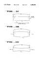
- FIGS. 1A-1Cillustrate piezoelectric voltages resulting from various forces applied to a ceramic or crystal element.
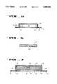
- FIG. 2Aillustrates the piezoelectric beam utilized in conjunction with the present invention.
- FIG. 2Billustrates the beam of FIG. 2A when the sensor of the present invention is subjected to a rotational displacement.
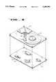
- FIG. 3is an exploded view of one embodiment of the present invention.
- FIG. 4is a bottom view of the sensor shown in FIG. 3, with the bottom cover removed.
- FIG. 5illustrates a cross-sectional side view of the outer case shown in the embodiment of FIG. 3.
- FIG. 6is a cross-sectional side view of the flywheel illustrated in the embodiment of FIG. 3.
- FIG. 7is a cross-sectional side view of the sensor illustrated in the embodiment of FIG. 3.
- FIG. 8illustrates a disk drive unit incorporating a shock sensor.
- Piezoelectricityis a property of certain classes of crystalline materials. Piezoelectric properties occur naturally in certain crystalline materials and can be induced in other polycrystalline ceramics. When mechanical pressure is applied to one of these materials the crystalline structure produces a voltage proportional to the applied force.
- Piezoelectric ceramicsprovide more versatility than natural piezoelectric crystals because their physical, chemical and piezoelectric characteristics can be tailored to specific applications.
- the mechanical and electrical axis of piezoelectric ceramic materialscan be precisely oriented in relation to the shape of the ceramic.
- the process that induces piezoelectric properties in these ceramicsis known as "poling".
- FIG. 1Aillustrates a piezoelectric ceramic element 11 which has been "poled” along a poling axis 10.
- ceramic element 11is shown oriented with a D.C. poling field (E P ) 12 from left to right.
- Poling field 12determines the orientation of the mechanical and electrical axis. Note that in FIG. 1A, the ceramic element is at rest (not subject to external mechanical stresses) so that no voltage appears across the length of element 11.
- FIGS. 1B and 1Cillustrate the generation of piezoelectric voltages from respective compressive and tensile forces applied to ceramic element 11.
- a compressive force F cis applied across the length of ceramic element 11.
- a voltage with the same polarity as the poling voltageresults from this compressive force applied parallel to the poling axis.
- a tensile force F Tis also applied parallel to the poling axis of element 11, resulting in a voltage with the opposite polarity across the length of the ceramic material.
- the deformation of ceramic element 11is exaggerated for illustration purposes. It is appreciated that the maximum dimensional change of a stressed ceramic element is relatively small--on the order of a few microinches. Similarly, the magnitude of the piezoelectric forces, actions and voltages are also relatively small. As will be discussed in more detail shortly, the present invention utilizes a piezoelectric material to produce an output voltage in response to rotational accelerations. This output voltage then is amplified by an electronic circuit, with the signal being used in one embodiment to disable the data writing process in a disk drive unit.
- FIG. 2Athere is shown a side view of the piezoelectric element utilized in the present invention to generate a voltage in response to a rotational acceleration.
- the piezoelectric material of FIG. 2Acomprises an elongated crystal or ceramic beam 20 having ends 22 and 23.
- Contacts 31a and 31bare attached on opposite sides of beam 20 near end 22, while contacts 32a and 32b are attached along opposite side of beam 20 near end 23.
- Disposed on opposite sides of the central region of beam 20are a third set of contacts 30a and 30b.
- contacts 30-32are utilized to apply voltages as part of the poling process.
- Contacts 31 and 32also function as voltage output terminals during motion sensing, as will be described shortly.
- beam 20is poled by applying a very high D.C. voltage (e.g., 10 kV) between terminals 31 and 30, and also terminals 32 and 30.
- the poling processestablishes the piezoelectric effect in beam 20.
- the poling fields, E Pare illustrated in FIG. 2A as being in a direction from the respective ends 22 and 23 toward the center of beam 20.
- a first poling fieldis produced by applying a very high voltage between terminals 31 and 30.
- a second poling fieldis established in the opposite direction in the other half of the bar by applying a high voltage between terminals 32 and 30.
- FIG. 2Billustrates the response of poled beam 20 (poled as described in conjunction with FIG. 2A) when subject to a rotational stress.
- the rotational stressis experienced as a rotational force, F r , applied to the center of the beam in a clockwise direction.
- F rrotational force
- This torquecauses piezoelectric voltages to be generated between each of the various terminals 30-32, as shown by voltages V a1 , V a2 , V b1 , V b2 .
- FIG. 2Billustrates voltage V a1 having a polarity opposite to the polarity of the poling field being generated between terminals 31a and 30a.
- the direction of voltage V a1is consistent with the application of a tensile force to this portion of beam 20.
- voltage V b2is shown being generated between terminals 32b and 30b in a direction opposite to that of the poling field, because of the tensile force experienced in this portion of beam 20.
- voltage V b1Due to the compressive force experienced in the portion of the beam between terminals 31b and 30b, voltage V b1 is generated with a polarity that is in the same direction as that of the poling field in this half of beam 20. The same is true of voltage V a2 which is generated between terminals 32a and 30a.
- FIG. 2Billustrates how appropriate connections may be made to a voltage sensing device, such as voltmeter 35, to measure or simply detect the output piezoelectric voltage generated by beam 20.
- the output voltage produced by beam 20ranges from several hundred millivolts up to a volt for stresses on the order of 10,000 psi. Also for a current embodiment, beam 20 has a cross-sectional area of approximately 20 ⁇ 30 mils, with a length of about 0.34 inches.
- Beam 20preferably comprises a piezoelectric ceramic material manufactured by Morgan Matroc, Inc. Several different types of piezoelectric ceramic materials may be utilized, such as Morgan Matroc, Inc. PZT-5A or PZT-5J. It is appreciated that other ceramic materials or crystals may also be utilized in the present invention. The only essential requirements are that the piezoelectric element be poled in the manner described in conjunction with FIG. 2A, and that it provide a piezoelectric output voltage which is detectable given the magnitude of the stresses that the sensor normally experiences.
- contacts 30-32comprise electroless nickel contacts. Gold may also be used for greater compatibility with tab automated bonding technologies.
- Each of the pads illustrated in FIG. 2Bis approximately 15 ⁇ 30 mils across.
- FIG. 3illustrates an exploded cross-sectional perspective view of shock sensor 25 including elongated ceramic beam 20. Shown attached to beam 20 are electrode pads 31 and 32 (the central contact pad 30 is not shown in FIG. 3). In sensor 25, beam 20 is mounted within the enclosure or cavity provided by outer case 40. As discussed earlier, ends 22 and 23 of beam 20 are attached to the interior surface of the enclosure formed by outer case 40. For example, ordinary epoxy glue may be utilized to secure the ends of beam 20 to the inside surface of outer case 40.
- the central region of crystal beam 20is attached to the raised portion 45 of flywheel 41.
- each half of flywheel 41is illustrated being connected by plate 38.
- flywheel 41When fully assembled, flywheel 41 only contacts portion 45 of the central region of beam 20, and nothing else. In other words, a clearance space is formed between flywheel 41 and the interior surface of case 40.
- a bottom cover 42is secured to flange 39 of the case 40. Again, ordinary epoxy glue may be utilized to secure bottom cover 42 to outer case 40.
- sensor 25may be mounted to a flat surface using tabs 47, which are shown to include an orifice for accommodating an attachment means such as a screw or rivet.
- flywheel 41When a moment is applied to the sensor--that is, when the body to which sensor 25 is attached is subjected to rotational acceleration--flywheel 41 tends to remain stationary because of its inertia. However, because flywheel 41 is only attached to the center of beam 20 (via raised attachment portion 45), and because beam 20 is also attached to the interior surface of case 40 at its ends, flywheel 41 torques beam 20 into an S-shape, as shown previously in FIG. 2. It is important to understand that flywheel 41 is totally free to move since it is only attached to beam 20 at the center of beam 20 via region 45. In essence, flywheel 41 is suspended within the enclosure formed by case 40 and bottom cover 42. This is best seen by the illustrations of FIGS. 4-7.
- FIG. 5is a cross-sectional side view of outer case 40.
- the interior space formed by the casingis shown in FIG. 5 by region 58, As before, tabs 47 are shown having an orifice 48 to accommodate various attachment methods.
- FIG. 6is a cross-sectional side view of flywheel 41 through cut lines 55 and 55' (see FIG. 4).
- FIG. 6clearly shows the raised attachment region 45.
- FIG. 7illustrates the assembled sensor 25 as shown through the cross-sectional side view of cut lines 55 and 55'.
- flywheel 41is shown being suspended from beam 20 via attachment region 45.
- a clearance space 53is formed between the outer sides of beam 20 and the interior sides surfaces of flywheel 41.
- FIG. 7also illustrates the clearance space 59 formed between the outer surface of flywheel 41 and the interior surface of the enclosure formed by case 40 and cover 42.
- clearance space 59is on the order of 1 to 5 mils wide.
- FIG. 4clearly illustrates the circular shape of flywheel 41 as it is suspended over elongated piezoelectric beam 20.
- the attachment area for flywheel 41 to beam 20is shown as rectangular region 45. In a current embodiment, this attachment area is approximately 15 ⁇ 30 mils.
- Outer case 40comprises injection-molded plastic with the ends of beam 20 being bonded to the interior surface of case 40 using an ordinary glue 51, such as epoxy.
- sensor 25includes an opening in either cover 42 or case 40 to accommodate the sensor wires.
- these wireswould typically be soldered to the printed circuit board on which sensor 25 is mounted. As explained earlier, these wires couple the piezoelectric voltage of beam 20 to an appropriate voltage sensing device or circuit.
- FIG. 8illustrates the shock sensor of the present invention finding application in conjunction with a disk drive unit.
- sensor 25is mounted on a printed circuit board 60 with wires 59 being shown connected to appropriate circuitry to detect the piezoelectric voltage generated as a result of rotational displacement of the drive unit.
- wires 59may be coupled to a charge amplifier and then to a voltmeter or similar sensor, such as a comparator or operational amplifier.
- a certain threshold leveli.e., a minimum detectable level
- the resulting signalmay be used to disable or turn-off the electronic circuitry on board 60 utilized in conjunction with the transfer of data to magnetic disk 61.
- the stiffness or first resonant frequency of flywheel 41 against beam 20 in a current embodimentis greater than 20 KHz. This provides the necessary response time needed to turn-off the write gate circuitry on board 60 under typical high shock conditions.
- sensor 25should be mounted in a plane which is either the same as, or substantially parallel to, the plane in which disk 61 resides.
- disk 61, actuator assembly 64, transducer or head 63 and actuator arm 62all lie in a first general plane.
- printed circuit board 60lies in a second plane substantially parallel to the plane formed by disk 61.
- the senor 25may be mounted either on the top or bottom of board 60, or alternatively anywhere within the housing of the disk drive assembly, as long as beam 20 lies in the same general plane, or substantially parallel to, the plane in which disk 61 resides.
- the sensor of the present inventionmay be built in a variety of different embodiments.
- flywheel 41may be a multitude of different shapes--its primary function being to stress the crystal or ceramic beam in order to generate a piezoelectric voltage under rotational acceleration conditions.
- flywheel 41is cast from a low temperature eutectic metal such as solder or lead; however, an assortment of other materials may also be used. In most situations, it is desirable that flywheel 41 have a high mass in order to apply maximum torque to beam 20 under shock conditions.
Landscapes
- Physics & Mathematics (AREA)
- General Physics & Mathematics (AREA)
- Force Measurement Appropriate To Specific Purposes (AREA)
Abstract
Description
Claims (20)
Priority Applications (2)
| Application Number | Priority Date | Filing Date | Title |
|---|---|---|---|
| US08/191,988US5389850A (en) | 1994-02-04 | 1994-02-04 | Rotational shock sensor |
| PCT/US1995/001493WO1995021464A1 (en) | 1994-02-04 | 1995-02-03 | Rotational shock sensor |
Applications Claiming Priority (1)
| Application Number | Priority Date | Filing Date | Title |
|---|---|---|---|
| US08/191,988US5389850A (en) | 1994-02-04 | 1994-02-04 | Rotational shock sensor |
Publications (1)
| Publication Number | Publication Date |
|---|---|
| US5389850Atrue US5389850A (en) | 1995-02-14 |
Family
ID=22707766
Family Applications (1)
| Application Number | Title | Priority Date | Filing Date |
|---|---|---|---|
| US08/191,988Expired - LifetimeUS5389850A (en) | 1994-02-04 | 1994-02-04 | Rotational shock sensor |
Country Status (2)
| Country | Link |
|---|---|
| US (1) | US5389850A (en) |
| WO (1) | WO1995021464A1 (en) |
Cited By (12)
| Publication number | Priority date | Publication date | Assignee | Title |
|---|---|---|---|---|
| US5757582A (en)* | 1992-11-18 | 1998-05-26 | Calluna Technology Limited | Miniature hard disk drive system |
| US5773916A (en)* | 1993-03-01 | 1998-06-30 | Murata Manufacturing Co. Ltd. | Piezoelectric vibrator and acceleration sensor using the same |
| US5923487A (en)* | 1997-06-05 | 1999-07-13 | Maxtor Corporation | Integrated shock sensing device |
| US6031317A (en)* | 1997-09-17 | 2000-02-29 | Aeptec Microsystems, Inc. | Piezoelecric shock sensor |
| US6414813B2 (en) | 2000-02-07 | 2002-07-02 | Seagate Technology Llc | Rotational acceleration correction in a disc drive |
| US6882489B1 (en) | 2000-08-15 | 2005-04-19 | Maxtor Corporation | Dynamic off-track detector |
| US20050179341A1 (en)* | 2004-01-14 | 2005-08-18 | Brantner Paul C. | Method and apparatus for a high output sensor system |
| US20060181176A1 (en)* | 2003-04-22 | 2006-08-17 | Paul Brantner | Method and apparatus for an ambient energy battery recharge system |
| US7253982B1 (en) | 2000-08-15 | 2007-08-07 | Maxtor Corporation | Dynamic shock detection in disk drive using hair trigger timer |
| US20080150396A1 (en)* | 2006-12-20 | 2008-06-26 | Clingman Dan J | Energy harvesting apparatus and method |
| US20100207490A1 (en)* | 2009-02-13 | 2010-08-19 | Southern Taiwan University | Piezoelectric tactile sensor |
| US20250258193A1 (en)* | 2024-02-09 | 2025-08-14 | Industrial Consulting Automation Research Engineering SRL | Method and apparatus for automated production of piezoelectric accelerometers |
Families Citing this family (1)
| Publication number | Priority date | Publication date | Assignee | Title |
|---|---|---|---|---|
| RU2123219C1 (en)* | 1997-05-20 | 1998-12-10 | Научное конструкторско-технологическое бюро "Пьезоприбор" при Ростовском государственном университете | Vibratory gyroscope |
Citations (28)
| Publication number | Priority date | Publication date | Assignee | Title |
|---|---|---|---|---|
| US2963911A (en)* | 1959-02-18 | 1960-12-13 | Bell Telephone Labor Inc | Piezoresistive accelerometer |
| US3142991A (en)* | 1960-08-08 | 1964-08-04 | Lear Siegler Inc | Fluid rotor sensor |
| US3558936A (en)* | 1967-07-19 | 1971-01-26 | John J Horan | Resonant energy-conversion system |
| US3561832A (en)* | 1969-12-05 | 1971-02-09 | Hewlett Packard Co | Quartz resonator pressure transducer |
| US3646536A (en)* | 1969-12-04 | 1972-02-29 | Sli Ind | Head-positioning apparatus |
| US3702997A (en)* | 1971-11-15 | 1972-11-14 | Diablo Systems Inc | Head loading system for magnetic memory disk drives |
| US3786457A (en)* | 1972-10-24 | 1974-01-15 | Memorex Corp | Disk recorder arm assembly mount |
| US3984873A (en)* | 1974-09-16 | 1976-10-05 | Information Storage Systems, Inc. | Head loading and unloading assembly for a magnetic disc drive having a rotary actuator |
| US4197737A (en)* | 1977-05-10 | 1980-04-15 | Applied Devices Corporation | Multiple sensing device and sensing devices therefor |
| US4211951A (en)* | 1976-03-29 | 1980-07-08 | Bruel & Kjaer A/S | Shear type prestressed piezoelectric force transducer |
| US4280156A (en)* | 1978-03-24 | 1981-07-21 | Compagnie Internationale Pour L'informatique Cii-Honeywell Bull (Societe Anonyme) | Lightly loaded ramp-launched read/write device for a data carrier |
| US4315289A (en)* | 1979-10-09 | 1982-02-09 | International Business Machines Corporation | Magnetic disk drive machine |
| US4345473A (en)* | 1980-11-26 | 1982-08-24 | Shell Oil Company | Vertical component accelerometer |
| US4535374A (en)* | 1982-11-04 | 1985-08-13 | Amcodyne Incorporated | Whitney-type head loading/unloading apparatus |
| US4686592A (en)* | 1985-05-02 | 1987-08-11 | Carroll Thomas D | Disk drive assembly |
| US4718276A (en)* | 1986-04-10 | 1988-01-12 | Applied Technology Associates, Inc. | Angular motion sensor |
| US4754646A (en)* | 1987-01-30 | 1988-07-05 | Quartztronics, Inc. | Resonator pressure transducer structure and method of manufacture |
| US4862298A (en)* | 1988-03-11 | 1989-08-29 | Magnetic Peripherals Inc. | Shock load detection device |
| US4933785A (en)* | 1988-03-01 | 1990-06-12 | Prairietek Corporation | Disk drive apparatus using dynamic loading/unloading |
| US5025336A (en)* | 1989-11-06 | 1991-06-18 | Prairietek Corporation | Disk drive apparatus |
| US5027241A (en)* | 1989-06-01 | 1991-06-25 | Quantum Corporation | Data head load beam for height compacted, low power fixed head and disk assembly |
| US5049776A (en)* | 1988-11-09 | 1991-09-17 | Aisin Seiki Kabushiki Kaisha | Apparatus for detecting rotation |
| US5067351A (en)* | 1989-10-25 | 1991-11-26 | Applied Technology Associates, Inc. | Magnetohydrodynamic angular rate sensor for measuring large angular rates |
| WO1992011630A1 (en)* | 1990-12-19 | 1992-07-09 | Integral Peripherals, Inc. | Rigid disk drive with dynamic head loading apparatus |
| US5170104A (en)* | 1991-08-20 | 1992-12-08 | Applied Technology Corporation | Linear actuator control system for platform stabilization |
| US5176030A (en)* | 1990-11-28 | 1993-01-05 | Applied Technology Associates, Inc. | Low frequency angular velocity sensor |
| US5189575A (en)* | 1989-10-06 | 1993-02-23 | Mitsubishi Denki Kabushiki Kaisha | Read/write head retract mechanism |
| US5272922A (en)* | 1991-03-06 | 1993-12-28 | Watson Industries, Inc. | Vibrating element angular rate sensor system and north seeking gyroscope embodiment thereof |
- 1994
- 1994-02-04USUS08/191,988patent/US5389850A/ennot_activeExpired - Lifetime
- 1995
- 1995-02-03WOPCT/US1995/001493patent/WO1995021464A1/enactiveApplication Filing
Patent Citations (28)
| Publication number | Priority date | Publication date | Assignee | Title |
|---|---|---|---|---|
| US2963911A (en)* | 1959-02-18 | 1960-12-13 | Bell Telephone Labor Inc | Piezoresistive accelerometer |
| US3142991A (en)* | 1960-08-08 | 1964-08-04 | Lear Siegler Inc | Fluid rotor sensor |
| US3558936A (en)* | 1967-07-19 | 1971-01-26 | John J Horan | Resonant energy-conversion system |
| US3646536A (en)* | 1969-12-04 | 1972-02-29 | Sli Ind | Head-positioning apparatus |
| US3561832A (en)* | 1969-12-05 | 1971-02-09 | Hewlett Packard Co | Quartz resonator pressure transducer |
| US3702997A (en)* | 1971-11-15 | 1972-11-14 | Diablo Systems Inc | Head loading system for magnetic memory disk drives |
| US3786457A (en)* | 1972-10-24 | 1974-01-15 | Memorex Corp | Disk recorder arm assembly mount |
| US3984873A (en)* | 1974-09-16 | 1976-10-05 | Information Storage Systems, Inc. | Head loading and unloading assembly for a magnetic disc drive having a rotary actuator |
| US4211951A (en)* | 1976-03-29 | 1980-07-08 | Bruel & Kjaer A/S | Shear type prestressed piezoelectric force transducer |
| US4197737A (en)* | 1977-05-10 | 1980-04-15 | Applied Devices Corporation | Multiple sensing device and sensing devices therefor |
| US4280156A (en)* | 1978-03-24 | 1981-07-21 | Compagnie Internationale Pour L'informatique Cii-Honeywell Bull (Societe Anonyme) | Lightly loaded ramp-launched read/write device for a data carrier |
| US4315289A (en)* | 1979-10-09 | 1982-02-09 | International Business Machines Corporation | Magnetic disk drive machine |
| US4345473A (en)* | 1980-11-26 | 1982-08-24 | Shell Oil Company | Vertical component accelerometer |
| US4535374A (en)* | 1982-11-04 | 1985-08-13 | Amcodyne Incorporated | Whitney-type head loading/unloading apparatus |
| US4686592A (en)* | 1985-05-02 | 1987-08-11 | Carroll Thomas D | Disk drive assembly |
| US4718276A (en)* | 1986-04-10 | 1988-01-12 | Applied Technology Associates, Inc. | Angular motion sensor |
| US4754646A (en)* | 1987-01-30 | 1988-07-05 | Quartztronics, Inc. | Resonator pressure transducer structure and method of manufacture |
| US4933785A (en)* | 1988-03-01 | 1990-06-12 | Prairietek Corporation | Disk drive apparatus using dynamic loading/unloading |
| US4862298A (en)* | 1988-03-11 | 1989-08-29 | Magnetic Peripherals Inc. | Shock load detection device |
| US5049776A (en)* | 1988-11-09 | 1991-09-17 | Aisin Seiki Kabushiki Kaisha | Apparatus for detecting rotation |
| US5027241A (en)* | 1989-06-01 | 1991-06-25 | Quantum Corporation | Data head load beam for height compacted, low power fixed head and disk assembly |
| US5189575A (en)* | 1989-10-06 | 1993-02-23 | Mitsubishi Denki Kabushiki Kaisha | Read/write head retract mechanism |
| US5067351A (en)* | 1989-10-25 | 1991-11-26 | Applied Technology Associates, Inc. | Magnetohydrodynamic angular rate sensor for measuring large angular rates |
| US5025336A (en)* | 1989-11-06 | 1991-06-18 | Prairietek Corporation | Disk drive apparatus |
| US5176030A (en)* | 1990-11-28 | 1993-01-05 | Applied Technology Associates, Inc. | Low frequency angular velocity sensor |
| WO1992011630A1 (en)* | 1990-12-19 | 1992-07-09 | Integral Peripherals, Inc. | Rigid disk drive with dynamic head loading apparatus |
| US5272922A (en)* | 1991-03-06 | 1993-12-28 | Watson Industries, Inc. | Vibrating element angular rate sensor system and north seeking gyroscope embodiment thereof |
| US5170104A (en)* | 1991-08-20 | 1992-12-08 | Applied Technology Corporation | Linear actuator control system for platform stabilization |
Non-Patent Citations (2)
| Title |
|---|
| "Retracting Reciprocating Magnetic Stripe Read Head Drive", R. A. Hampson and J. V. Vetrone, IBM Technical Disclosure Bulletin vol. 25, No. 4, pp. 1827-1828, Sep. 1981. |
| Retracting Reciprocating Magnetic Stripe Read Head Drive , R. A. Hampson and J. V. Vetrone, IBM Technical Disclosure Bulletin vol. 25, No. 4, pp. 1827 1828, Sep. 1981.* |
Cited By (21)
| Publication number | Priority date | Publication date | Assignee | Title |
|---|---|---|---|---|
| US5757582A (en)* | 1992-11-18 | 1998-05-26 | Calluna Technology Limited | Miniature hard disk drive system |
| US5773916A (en)* | 1993-03-01 | 1998-06-30 | Murata Manufacturing Co. Ltd. | Piezoelectric vibrator and acceleration sensor using the same |
| US5923487A (en)* | 1997-06-05 | 1999-07-13 | Maxtor Corporation | Integrated shock sensing device |
| US6018431A (en)* | 1997-06-05 | 2000-01-25 | Maxtor Corporation | Disk drive with shock evaluator |
| US6031317A (en)* | 1997-09-17 | 2000-02-29 | Aeptec Microsystems, Inc. | Piezoelecric shock sensor |
| US6414813B2 (en) | 2000-02-07 | 2002-07-02 | Seagate Technology Llc | Rotational acceleration correction in a disc drive |
| US7154690B1 (en)* | 2000-08-15 | 2006-12-26 | Maxtor Corporation | Dynamic shock detection in disk drive using accumulated average position error |
| US6882489B1 (en) | 2000-08-15 | 2005-04-19 | Maxtor Corporation | Dynamic off-track detector |
| US7253982B1 (en) | 2000-08-15 | 2007-08-07 | Maxtor Corporation | Dynamic shock detection in disk drive using hair trigger timer |
| US7183693B2 (en) | 2003-04-22 | 2007-02-27 | Infinite Power Solutions, Inc. | Method and apparatus for an ambient energy battery recharge system |
| US20060181176A1 (en)* | 2003-04-22 | 2006-08-17 | Paul Brantner | Method and apparatus for an ambient energy battery recharge system |
| US7102271B2 (en)* | 2004-01-14 | 2006-09-05 | Infinite Power Solutions, Inc. | Method and apparatus for a high output sensor system |
| US20060175931A1 (en)* | 2004-01-14 | 2006-08-10 | Brantner Paul C | Method and apparatus for a high output sensor system |
| US20050179341A1 (en)* | 2004-01-14 | 2005-08-18 | Brantner Paul C. | Method and apparatus for a high output sensor system |
| US7274130B2 (en) | 2004-01-14 | 2007-09-25 | Infinite Power Solutions, Inc. | Method and apparatus for a high output sensor system |
| US20080150396A1 (en)* | 2006-12-20 | 2008-06-26 | Clingman Dan J | Energy harvesting apparatus and method |
| US7541720B2 (en) | 2006-12-20 | 2009-06-02 | The Boeing Company | Energy harvesting apparatus and method |
| US20100207490A1 (en)* | 2009-02-13 | 2010-08-19 | Southern Taiwan University | Piezoelectric tactile sensor |
| US7781940B1 (en)* | 2009-02-13 | 2010-08-24 | Southern Taiwan University | Piezoelectric tactile sensor |
| US8158533B2 (en) | 2009-02-13 | 2012-04-17 | Southern Taiwan University | Piezoelectric tactile sensor |
| US20250258193A1 (en)* | 2024-02-09 | 2025-08-14 | Industrial Consulting Automation Research Engineering SRL | Method and apparatus for automated production of piezoelectric accelerometers |
Also Published As
| Publication number | Publication date |
|---|---|
| WO1995021464A1 (en) | 1995-08-10 |
Similar Documents
| Publication | Publication Date | Title |
|---|---|---|
| US5389850A (en) | Rotational shock sensor | |
| JP4298911B2 (en) | Suspension for disk unit | |
| US8443672B2 (en) | Low-power shock and vibration sensors and methods of making sensors | |
| US6661618B2 (en) | Suspension for disc drive with insulating cover film on piezoelectric element | |
| US5452612A (en) | Multi-mode accelerometer | |
| US6262868B1 (en) | Method and structures used for connecting recording head signal wires in a microactuator | |
| US5959808A (en) | Shielded electrostatic microactuators for magnetic-head positioning such devices | |
| JP3716164B2 (en) | Head support mechanism | |
| US6031317A (en) | Piezoelecric shock sensor | |
| EP0538976B1 (en) | Apparatus for sensing operating shock on a disk drive | |
| EP0332317A2 (en) | Shock load detection device | |
| US6195227B1 (en) | Integrated 3D limiters for microactuators | |
| US5721457A (en) | Shock isolation system with write inhibit | |
| US4905107A (en) | Torsion transducer for magnetic storage disk drives | |
| US5995334A (en) | Rotary electrostatic microactuator with area-efficient comb electrode arrangement | |
| US5982585A (en) | Rotary electrostatic microactuator with optimum flexure arrangement | |
| KR100906573B1 (en) | Acceleration sensor | |
| US4058843A (en) | Head and gimbal assembly | |
| EP0355289A1 (en) | Accelerometer | |
| US5378974A (en) | Vibration damping system | |
| KR0165714B1 (en) | Acceleration sensor and its manufacturing method | |
| JP2003168270A (en) | Magnetic head support mechanism and magnetic head positioning control mechanism | |
| US8964328B1 (en) | Shock sensor on an external surface of a disk drive base adjacent a disk drive printed circuit board | |
| US5058430A (en) | Sensor capsule mounting | |
| JP3732081B2 (en) | Magnetic disk unit |
Legal Events
| Date | Code | Title | Description |
|---|---|---|---|
| AS | Assignment | Owner name:MAXTOR CORPORATION, CALIFORNIA Free format text:ASSIGNMENT OF ASSIGNORS INTEREST;ASSIGNOR:WILMER RICHARD K.;REEL/FRAME:006885/0458 Effective date:19940202 | |
| STCF | Information on status: patent grant | Free format text:PATENTED CASE | |
| FPAY | Fee payment | Year of fee payment:4 | |
| FPAY | Fee payment | Year of fee payment:8 | |
| REMI | Maintenance fee reminder mailed | ||
| FPAY | Fee payment | Year of fee payment:12 | |
| AS | Assignment | Owner name:WELLS FARGO BANK, NATIONAL ASSOCIATION, AS COLLATERAL AGENT AND SECOND PRIORITY REPRESENTATIVE, CALIFORNIA Free format text:SECURITY AGREEMENT;ASSIGNORS:MAXTOR CORPORATION;SEAGATE TECHNOLOGY LLC;SEAGATE TECHNOLOGY INTERNATIONAL;REEL/FRAME:022757/0017 Effective date:20090507 Owner name:JPMORGAN CHASE BANK, N.A., AS ADMINISTRATIVE AGENT AND FIRST PRIORITY REPRESENTATIVE, NEW YORK Free format text:SECURITY AGREEMENT;ASSIGNORS:MAXTOR CORPORATION;SEAGATE TECHNOLOGY LLC;SEAGATE TECHNOLOGY INTERNATIONAL;REEL/FRAME:022757/0017 Effective date:20090507 Owner name:JPMORGAN CHASE BANK, N.A., AS ADMINISTRATIVE AGENT Free format text:SECURITY AGREEMENT;ASSIGNORS:MAXTOR CORPORATION;SEAGATE TECHNOLOGY LLC;SEAGATE TECHNOLOGY INTERNATIONAL;REEL/FRAME:022757/0017 Effective date:20090507 Owner name:WELLS FARGO BANK, NATIONAL ASSOCIATION, AS COLLATE Free format text:SECURITY AGREEMENT;ASSIGNORS:MAXTOR CORPORATION;SEAGATE TECHNOLOGY LLC;SEAGATE TECHNOLOGY INTERNATIONAL;REEL/FRAME:022757/0017 Effective date:20090507 | |
| AS | Assignment | Owner name:SEAGATE TECHNOLOGY LLC, CALIFORNIA Free format text:RELEASE;ASSIGNOR:JPMORGAN CHASE BANK, N.A., AS ADMINISTRATIVE AGENT;REEL/FRAME:025662/0001 Effective date:20110114 Owner name:MAXTOR CORPORATION, CALIFORNIA Free format text:RELEASE;ASSIGNOR:JPMORGAN CHASE BANK, N.A., AS ADMINISTRATIVE AGENT;REEL/FRAME:025662/0001 Effective date:20110114 Owner name:SEAGATE TECHNOLOGY INTERNATIONAL, CALIFORNIA Free format text:RELEASE;ASSIGNOR:JPMORGAN CHASE BANK, N.A., AS ADMINISTRATIVE AGENT;REEL/FRAME:025662/0001 Effective date:20110114 Owner name:SEAGATE TECHNOLOGY HDD HOLDINGS, CALIFORNIA Free format text:RELEASE;ASSIGNOR:JPMORGAN CHASE BANK, N.A., AS ADMINISTRATIVE AGENT;REEL/FRAME:025662/0001 Effective date:20110114 | |
| AS | Assignment | Owner name:THE BANK OF NOVA SCOTIA, AS ADMINISTRATIVE AGENT, CANADA Free format text:SECURITY AGREEMENT;ASSIGNOR:SEAGATE TECHNOLOGY LLC;REEL/FRAME:026010/0350 Effective date:20110118 Owner name:THE BANK OF NOVA SCOTIA, AS ADMINISTRATIVE AGENT, Free format text:SECURITY AGREEMENT;ASSIGNOR:SEAGATE TECHNOLOGY LLC;REEL/FRAME:026010/0350 Effective date:20110118 | |
| AS | Assignment | Owner name:EVAULT INC. (F/K/A I365 INC.), CALIFORNIA Free format text:TERMINATION AND RELEASE OF SECURITY INTEREST IN PATENT RIGHTS;ASSIGNOR:WELLS FARGO BANK, NATIONAL ASSOCIATION, AS COLLATERAL AGENT AND SECOND PRIORITY REPRESENTATIVE;REEL/FRAME:030833/0001 Effective date:20130312 Owner name:SEAGATE TECHNOLOGY US HOLDINGS, INC., CALIFORNIA Free format text:TERMINATION AND RELEASE OF SECURITY INTEREST IN PATENT RIGHTS;ASSIGNOR:WELLS FARGO BANK, NATIONAL ASSOCIATION, AS COLLATERAL AGENT AND SECOND PRIORITY REPRESENTATIVE;REEL/FRAME:030833/0001 Effective date:20130312 Owner name:SEAGATE TECHNOLOGY LLC, CALIFORNIA Free format text:TERMINATION AND RELEASE OF SECURITY INTEREST IN PATENT RIGHTS;ASSIGNOR:WELLS FARGO BANK, NATIONAL ASSOCIATION, AS COLLATERAL AGENT AND SECOND PRIORITY REPRESENTATIVE;REEL/FRAME:030833/0001 Effective date:20130312 Owner name:SEAGATE TECHNOLOGY INTERNATIONAL, CAYMAN ISLANDS Free format text:TERMINATION AND RELEASE OF SECURITY INTEREST IN PATENT RIGHTS;ASSIGNOR:WELLS FARGO BANK, NATIONAL ASSOCIATION, AS COLLATERAL AGENT AND SECOND PRIORITY REPRESENTATIVE;REEL/FRAME:030833/0001 Effective date:20130312 | |
| AS | Assignment | Owner name:SEAGATE TECHNOLOGY PUBLIC LIMITED COMPANY, CALIFORNIA Free format text:RELEASE BY SECURED PARTY;ASSIGNOR:THE BANK OF NOVA SCOTIA;REEL/FRAME:072193/0001 Effective date:20250303 Owner name:SEAGATE TECHNOLOGY, CALIFORNIA Free format text:RELEASE BY SECURED PARTY;ASSIGNOR:THE BANK OF NOVA SCOTIA;REEL/FRAME:072193/0001 Effective date:20250303 Owner name:SEAGATE TECHNOLOGY HDD HOLDINGS, CALIFORNIA Free format text:RELEASE BY SECURED PARTY;ASSIGNOR:THE BANK OF NOVA SCOTIA;REEL/FRAME:072193/0001 Effective date:20250303 Owner name:I365 INC., CALIFORNIA Free format text:RELEASE BY SECURED PARTY;ASSIGNOR:THE BANK OF NOVA SCOTIA;REEL/FRAME:072193/0001 Effective date:20250303 Owner name:SEAGATE TECHNOLOGY LLC, CALIFORNIA Free format text:RELEASE BY SECURED PARTY;ASSIGNOR:THE BANK OF NOVA SCOTIA;REEL/FRAME:072193/0001 Effective date:20250303 Owner name:SEAGATE TECHNOLOGY INTERNATIONAL, CAYMAN ISLANDS Free format text:RELEASE BY SECURED PARTY;ASSIGNOR:THE BANK OF NOVA SCOTIA;REEL/FRAME:072193/0001 Effective date:20250303 Owner name:SEAGATE HDD CAYMAN, CAYMAN ISLANDS Free format text:RELEASE BY SECURED PARTY;ASSIGNOR:THE BANK OF NOVA SCOTIA;REEL/FRAME:072193/0001 Effective date:20250303 Owner name:SEAGATE TECHNOLOGY (US) HOLDINGS, INC., CALIFORNIA Free format text:RELEASE BY SECURED PARTY;ASSIGNOR:THE BANK OF NOVA SCOTIA;REEL/FRAME:072193/0001 Effective date:20250303 |