US5389100A - Controller for manipulation of instruments within a catheter - Google Patents
Controller for manipulation of instruments within a catheterDownload PDFInfo
- Publication number
- US5389100A US5389100AUS07/788,338US78833891AUS5389100AUS 5389100 AUS5389100 AUS 5389100AUS 78833891 AUS78833891 AUS 78833891AUS 5389100 AUS5389100 AUS 5389100A
- Authority
- US
- United States
- Prior art keywords
- instrument
- catheter
- section
- drive
- controller
- Prior art date
- Legal status (The legal status is an assumption and is not a legal conclusion. Google has not performed a legal analysis and makes no representation as to the accuracy of the status listed.)
- Expired - Fee Related
Links
Images


Classifications
- A—HUMAN NECESSITIES
- A61—MEDICAL OR VETERINARY SCIENCE; HYGIENE
- A61M—DEVICES FOR INTRODUCING MEDIA INTO, OR ONTO, THE BODY; DEVICES FOR TRANSDUCING BODY MEDIA OR FOR TAKING MEDIA FROM THE BODY; DEVICES FOR PRODUCING OR ENDING SLEEP OR STUPOR
- A61M25/00—Catheters; Hollow probes
- A61M25/01—Introducing, guiding, advancing, emplacing or holding catheters
- A61M25/0105—Steering means as part of the catheter or advancing means; Markers for positioning
- A61M25/0119—Eversible catheters
- A—HUMAN NECESSITIES
- A61—MEDICAL OR VETERINARY SCIENCE; HYGIENE
- A61M—DEVICES FOR INTRODUCING MEDIA INTO, OR ONTO, THE BODY; DEVICES FOR TRANSDUCING BODY MEDIA OR FOR TAKING MEDIA FROM THE BODY; DEVICES FOR PRODUCING OR ENDING SLEEP OR STUPOR
- A61M25/00—Catheters; Hollow probes
- A61M25/01—Introducing, guiding, advancing, emplacing or holding catheters
- A61M25/0105—Steering means as part of the catheter or advancing means; Markers for positioning
- A61M25/0113—Mechanical advancing means, e.g. catheter dispensers
Definitions
- An everting cathetertypically includes an outer catheter having an outer catheter lumen and an inner catheter movable longitudinally in the outer catheter lumen and having an inner catheter lumen.
- An everting elementis coupled to the outer catheter and the inner catheter so that, with movement of the inner catheter distally in the outer catheter lumen, the everting element can be everted through an opening in the outer catheter.
- An everting catheter of this typecan be inserted through a passage in the human body with the everting element in an inverted position.
- An elongated, flexible instrumentcan then be introduced through the inner catheter lumen and the everting element to position the instrument into a desired body region and accomplish any of a variety of medical procedures and/or viewing of internal body regions.
- an everting catheterrequires the control and manipulation of several different components. For example, movement and control of the inner catheter is required in connection with the eversion and inversion of the everting element, and movement and control of the instrument relative to the inner catheter is necessary in order to properly position the instrument within the body of the patient. In addition, the outer catheter must be properly positioned. Because of these multiple controlling and positioning tasks, the use of an everting catheter system commonly requires two attendants.
- Non-everting cathetersalso may require multiple controlling and positioning functions during use.
- a non-everting cathetermay have an instrument extending through the lumen of the catheter and into the body of the patient. During use, it is commonly necessary to position the catheter and the instrument within the patient; however, unlike everting catheters, only a single catheter needs to be positioned.
- a guidewire torquerincludes a collet clamped onto a guidewire which extends through an access catheter or angioplasty catheter.
- the torquerallows the operator to operate the guidewire about a central axis and move the guidewire proximally and distally.
- the torquerdoes not control the position of the catheter.
- a hand-held controllerattached to a guiding catheter.
- the controllerrotates a drive cable or instrument shaft which manipulates cutting surfaces on the distal end of the instrument.
- the controllerhas a pull knob which can advance and withdraw the cutting surface of the instrument within the lumen of the catheter.
- Other controllers of this typerotate an instrument or drive cable which imparts rotational energy to the cutting surface.
- a controller of this typemay also have a pistol-trigger grip which allows an ultrasonic ablative surface to be advanced and withdrawn.
- Other types of pistol-trigger grip deviceswhich are attached to primary catheters can be used for grabbing forceps or scissors.
- This inventionprovides a controller which greatly simplifies catheter and instrument positioning and control within the body of a patient.
- the inventionis particularly adapted for use with an everting catheter where positioning and control functions are more complex, this invention is also adapted for use with a non-everting catheter.
- this inventionprovides an everting catheter system which includes an everting catheter and a controller.
- the controlleris coupled to the inner catheter for moving the inner catheter in the outer catheter lumen and for moving the instrument in the inner catheter lumen relative to the inner catheter. Because the controller is coupled to the inner catheter, it can move and position the inner catheter.
- the controllerhas the capability of moving and positioning the instrument in the inner catheter lumen. The controller enables one-handed control and positioning of both the inner catheter and the instrument leaving the other hand of the attendant free. This converts what has characteristically been a two-attendant operation to a one-attendant operation.
- the movement of the instrument in the inner catheter lumenmay be longitudinal and/or rotational.
- the controllerpreferably includes a driving device for moving the instrument.
- the driving devicemay take many different forms and, in a preferred construction, includes a movable, endless member for contacting and driving the instrument longitudinally in the inner catheter lumen.
- the movable, endless membermay be a drive wheel, drive belt, drive chain or other endless member.
- One advantage of an endless, movable memberis that no shuttle or back and forth movement is necessary for it to move the instrument through substantial distances. In addition, it promotes compactness and simplicity of the controller.
- the driving devicealso includes a secondary wheel engageable with the instrument and cooperable with the drive wheel for moving the instrument.
- a secondary wheelengageable with the instrument and cooperable with the drive wheel for moving the instrument.
- the secondary wheelmay also be a drive wheel or it may be an idler wheel which is driven solely by virtue of its contact with the instrument.
- the driving devicemay be driven manually or with a motor.
- a manual drivehas the advantage of light weight, lower cost and retention of "feel" by the operator.
- an endless, movable memberhaving a region engageable by a thumb of an operator to impart a manual driving force to the driving device for moving the instrument longitudinally.
- This latter endless, movable membermay be the same endless movable member which contacts and drives the instrument or it may be a separate member contacted by the thumb which drives the endless, movable member directly or through intermediate drive wheels or the like.
- the controlleris also able to rotate the instrument. At least a portion of the controller, and preferably the driving device, may be movable or rotatable to accomplish this function.
- the controllerpreferably includes a supporting structure which in turn may include a housing coupled to a proximal end portion of the inner catheter.
- the housingmay be a separate member permanently or releasably coupled to the proximal end portion of the inner catheter.
- the housing and inner cathetermay be of one-piece construction, in which event, the coupling of the housing to the catheter is an integral coupling.
- the housinghas a passage which communicates with the inner catheter lumen and which is adapted to receive the instrument.
- the housingcan be of various different constructions, it preferably forms a handle section or handle which is adapted to be manually grasped.
- the housingextends proximally of the region of the endless, movable member, which is engageable and drivable by the thumb of an operator, to form the handle.
- the housingcan advantageously be used to provide for rotation of the instrument.
- the housingincludes a rotatable section or drive section rotatable generally about the axis of the passage, and the driving device is carried by the rotatable section ,and is capable of gripping the instrument. Accordingly, rotation of the rotatable section rotates the instrument.
- the housingis a separate member which is coupled to the proximal end portion of the catheter.
- the housing of the controllercan advantageously include a mounting section adapted to be coupled to the catheter.
- the drive section of the housingis coupled to both the handle and the mounting section intermediate the handle and the mounting section.
- the peripheral surfaces of these wheelsare arranged in generally confronting relationship and adapted to receive the instrument therebetween. At least one of these peripheral surfaces of the wheels may have a groove for receiving the instrument.
- the grooveis particularly advantageous for an instrument, such as certain endoscopes, having a relatively fragile lens and/or optical system near the distal end portion of the instrument and a cross section which reduces toward the distal end. Instruments of this type can be slid through this groove without damaging the optical system, and the thicker, more proximal regions of the instrument can still be gripped with sufficient firmness by the wheels to form a driving connection between the wheels and the instrument.
- the controllerpreferably includes means in the passage for guiding the instrument from the proximal portion of the passage to the driving device.
- the guiding meansincludes first and second spaced alignment tabs for guiding the instrument between the drive wheel and the secondary wheel.
- the wheelspreferably define first and second annular spaces, and the tabs are received in the annular spaces, respectively.
- interlocking projections and recessesmay be provided on the instrument and the driving device to provide a positive driving relationship between these components.
- some of these projections and recessesare on the peripheral surface of the drive wheel of the driving device.
- the projections on the instrumentare preferably located proximally of the distal end of the instrument, and at least some of the projections are along a region of the instrument which is at the driving device when the distal end of the instrument is adjacent the opening of the catheter.
- the controllermay be coupled to the proximal end portion of a catheter which may be either everting or non-everting.
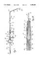
- FIG. 1is a plan view illustrating one form of catheter system constructed in accordance with the teachings of this invention with the everting element everted and the instrument extending from the everting element.
- FIG. 1Ais an enlarged, axial, fragmentary sectional view illustrating a distal region of the everting catheter of FIG. 1 with the everting element everted.
- FIG. 2is a perspective view with parts broken away of one form of controller constructed in accordance with the teachings of this invention.
- FIG. 3is a sectional view taken generally along line 3--3 of FIG. 2 and also illustrating a portion of the inner catheter.
- FIGS. 4, 5 and 6are enlarged sectional views taken generally along lines 4--4, 5--5 and 6--6, respectively, of FIG. 3.
- FIG. 6illustrates in phantom lines the rotation of the rotatable section of the housing.
- FIG. 7is a plan view of a non-everting catheter system constructed in accordance with the teachings of this invention.
- FIG. 8is a fragmentary, plan view partially in section illustrating one way to provide a positive drive connection between the drive wheel and the instrument.
- FIG. 1shows an everting catheter system 11 which is particularly adapted for accessing the fallopian tubes; however, it should be understood that the features of this invention are also applicable to catheter systems adapted for other purposes.
- the catheter system 11generally comprises an outer catheter 13, and inner catheter 15, an everting element 17 (FIG. 1A) and an elongated instrument 19.
- the outer catheter 13includes an elongated, flexible catheter body 21 and an outer catheter fitting 23 coupled to the proximal end of the catheter body 21.
- the outer catheter 13has an outer catheter lumen 25 (FIG. 1A) which extends from a proximal opening 27, which is provided by the outer catheter fitting 23, to a distal opening 29 (FIG. 1A) which, in this embodiment, is at the distal end of the catheter body 21.
- the catheter body 21may have multiple lumens, if desired, and the distal opening 29 need not be at the distal end of the catheter body.
- the catheter body 21has a distal end portion 31 which, in its unstressed condition, may be straight or of any other shape designed to best gain access to a desired region of the body. As shown in FIG. 1, the distal end portion 31 is curved and forms a portion of a circular arc in the unstressed condition, and this facilitates access to the ostia of the fallopian tubes. However, the shape of the distal end portion 31 forms no part of this invention, and the distal end portion is shown for convenience in FIG. 1A as linear.
- the outer catheter 13may be of conventional construction, and the catheter body 21 may be constructed of a flexible, biocompatible polymeric material.
- the outer catheter fitting 23has an injection leg 33 through which an inflation media can be supplied to the outer catheter lumen 25 to control the inversion and eversion of the everting element 17 in a known manner.
- the inner catheter 15is extendible through the proximal opening 27 of the outer catheter 13 and is movable longitudinally in the outer catheter lumen 25.
- the inner catheter 15also includes a catheter body 35 and an inner catheter fitting 37 coupled to the proximal end of the catheter body 35.
- the inner catheter 15has an inner catheter lumen 39 (FIG. 1A) which extends between a proximal opening 41 (FIG. 3) provided by one leg of the inner catheter fitting 37 and a distal opening 43 (FIG. 1A) at the distal end 44 of the catheter body 35.
- the catheter body 35may be flexible or rigid depending upon the nature and purpose of the catheter system 11. However, in this embodiment, a distal region of the catheter body 35 is flexible such that the portion of the catheter body 35 that is within the distal end portion 31 in all positions of the inner catheter 15 relative to the outer catheter 13 is flexible.
- the fitting 37has an injection leg 45 which can be used, for example, for injecting irrigation fluid, a contrast dye or drugs into the inner catheter lumen 39.
- the leg 45can also be used for aspiration, if desired.
- the everting element 17(FIG. 1A) is a thin, flexible membrane which is constructed of a suitable polymeric material.
- the everting element 17is bonded as by an adhesive to the catheter body 21 of the outer catheter 13 closely adjacent the distal opening 29 and to a distal tip region of the catheter body 35 of the inner catheter 15 in accordance with known techniques.
- Thisforms a chamber 47 with the catheter body 21 of the outer catheter 13. Consequently, inflation media from the injection leg 33 acting in the chamber 47 can bring about inversion and eversion of the everting element 17.
- the everting element 17has a distal end 49 which, in the everted position of FIG. 1A, is located distally of the distal opening 29.
- the everting element 17forms an extension 50 of the inner catheter lumen 39.
- the instrument 19is elongated and flexible.
- the instrument 19is introduced to the inner catheter lumen 39 through the proximal opening 41 and can be moved both proximally and distally relative to the inner catheter 15 independently of the inner catheter.
- the instrument 19terminates distally in a distal end 51 (FIG. 1A).
- the instrument 19is an endoscope for examination of the fallopian tubes.
- the instrumentmay be virtually any elongated, flexible instrument for medical purposes, such as a guidewire or other instrument for either visualizing or carrying out a procedure on an interior region of the body of a patient.
- the catheter system 11 as described to this point in the Description of the Preferred Embodimentmay be conventional. However, the catheter system 11 departs from conventional systems in providing a controller 53 (FIG. 1) coupled to the inner catheter 15 for moving the inner catheter in the outer catheter lumen 25 and instrument 19 in the inner catheter lumen 39 relative to the inner catheter.
- a controller 53FIG. 1
- the controller 53includes a supporting structure which, in this embodiment, is in the form of a housing 55 (FIG. 2).
- the housing 55can be of different constructions, in this embodiment, it is constructed of a suitable hard polymeric material, and it has a passage 57 extending therethrough which is adapted to receive the instrument 19 (FIG. 3).
- the housing 55includes a mounting section 59 adapted to be coupled to the inner catheter 15, a drive section or rotatable section 61 and an elongated handle or handle section 63 which is adapted to be manually grasped.
- the mounting section 59includes a short, internally threaded tube having an inner conical projection 65, a head 67 integral with the tube and an annular groove 69 between the head and the tube.
- the handle section 63includes an elongated tube 71 and a tubular connector 73 which receives and is affixed to the proximal end of the tube 71.
- the connector 73has an annular groove 75.
- the grooves 75 and 69are received within openings in the drive section 61 to mount the drive section 61 and the handle section 63 for rotational movement about the axis of the passage 57 relative to the mounting section 59 as described more specifically below.
- the drive section 61is located between the mounting section 59 and the handle section 63 and has an opening 77.
- the controller 53includes a driving device 79 for moving the instrument 19 longitudinally in the inner catheter lumen 39 relative to the inner catheter 15.
- the driving device 79can take different forms, including various ratchet or shuttle devices, it preferably includes a movable endless member, such as a drive wheel 81 for contacting and driving the instrument 19 longitudinally.
- the driving device 79 in this embodimentalso includes a secondary wheel 83 which is cooperable with the drive wheel 81 for moving the instrument 19 longitudinally.
- the wheels 81 and 83are rotatably mounted on the drive section 61, and for that purpose, the drive section has opposite side walls 85 (FIGS. 4-6) joined by end walls 87 (FIGS. 2 and 3) and a transverse wall 89 (FIGS. 4-6).
- the drive section 61forms a container with the opening 77 being generally opposite the transverse wall 89.
- the drive section 61can be a one-piece member, in this embodiment, it comprises two molded half sections 90 (FIGS. 5 and 6) suitably adhered together.
- each of the wheelsincludes oppositely extending stub shafts 91 (FIG. 4) received in inwardly facing bearings 93 integrally formed on the side walls 85, respectively. This mounts the wheels 81 and 83 for rotation about parallel rotational axes which extend transverse to the axis of the passage 57.
- the wheels 81 and 83can be configured in different ways, in this embodiment, they are identical, and each of them is of one-piece integral construction and includes a central drive disc 95 having a peripheral surface 97 and outer discs 99 having gear teeth 101 on their peripheral surfaces. With the wheels 81 and 83 rotatably mounted within the drive section 61 of the housing 55, the peripheral surfaces 97 are in generally confronting relationship and adapted to receive the instrument 19 therebetween so that, upon rotation of the drive wheel 81, the instrument 19 can be moved longitudinally in the passage 57 of the housing.
- the gear teeth 101 of the drive wheel 81drivingly engage the gear teeth 101 of the secondary wheel 83 so that there is a positive drive connection between these two wheels, and slippage between these wheels is, therefore, prevented.
- the controller 53may be constructed so that the secondary wheel 83 can be directly manually driven.
- the opening 77exposes a region of a portion of the drive wheel 81, and such region is engageable by a thumb of an operator to impart manual driving force to the drive wheel 81.
- the exposed portionincludes a portion of the peripheral surface of the drive wheel 81, i.e., a portion of the peripheral surface 97 and a portion of the peripheral surface containing the gear teeth 101.
- the drive section 61completely encloses the wheels 81 and 83, except for this exposed portion of the drive wheel 81 so that the driving motion of the driving device 79 is unlikely to be unintentionally impeded.
- the handle section 63 of the housing 55extends proximally of the region of the drive wheel 81 which is exposed through the opening 77 to conveniently position the handle section for manual grasping of the controller 53 and the exposed region of the drive wheel for being manually driven by the thumb of the operator.
- the wheels 81 and 83can be constructed of various different hard and soft materials, and it is not necessary that they both be constructed of the same material.
- the wheels 81 and 83may be constructed of a metal, they may also be constructed of soft material, such as a soft rubber or a relatively hard polymeric material, such as hard polyurethane. If desired, one or both of the wheels 81 and 83 may have an outer, relatively softer, jacket.
- each of the wheels 81 and 83is of one-piece integral construction and is constructed of a relatively hard polymeric material to provide a strong positive driving connection between the interengaging teeth 101.
- the peripheral surfaces 97 of the wheels 81 and 83each have a groove 103 arranged to confront the corresponding groove of the other wheel as shown in FIG. 4. These grooves 103 are sized and adapted to receive the instrument 19 with the desired amount of compressive force for driving the instrument 19 without damaging the instrument.
- the instrument 19is an endoscope of the type having a distal end portion 105 (FIG. 1) which contains relatively delicate optics and which is of smaller cross-sectional area than a region of the instrument located proximally of a location 107 (FIG. 1) on the instrument.
- the two grooves 103are sized to slidably receive the distal end portion 105 containing the delicate optics without compressively loading the distal end portion. It is not until the location 107 of the instrument 19 is located at the grooves 103 that the grooves begin to compressively load the instrument to form a driving connection therewith. In this manner, the instrument 19 can be more quickly advanced through the controller 53 up to the location 107 without turning of the wheels 81 and 83 and without risking damage to the optics in the distal end portion 105.
- the housing 55is constructed so that the drive section 61 and the handle section 63 are rotatable as a unit about the axis of the passage 57 relative to the mounting section 59.
- the connector 73has a head 109 (FIGS. 3 and 5) within the drive section 61.
- the head 109has lateral edges 111 (FIG. 5) which engage the opposite side walls 85, respectively, of the drive section 61 to prevent rotation of the connector 73 and the entire handle section 63 about the axis of the passage 57 relative to the drive section 61.
- the drive section 61 and the handle section 63are not relatively rotatable about the axis of the passage 57.
- the head 67 (FIGS. 3 and 6) of the mounting section 59is circular as viewed in FIG. 6 and is of small enough diameter so that the side walls 85 do not impede relative rotation between the mounting section 59 and the drive section 61 about the axis of the passage 57.
- the fit between the opening in the end wall 87 and the mounting section 59is sufficiently loose so as to permit this rotation.
- This structure which couples the drive section 61 to the mounting section 59 for relative rotationmay be considered to be a coupling.
- the controller 53can be coupled to the inner catheter 15 in various different ways, such as by constructing the housing 55 and the inner catheter fitting 37 of one-piece integral construction, in this embodiment, the housing 55 is a separate element, and the controller 53 is releasably coupled to the inner catheter 15.
- the inner catheter fitting 37has a leg 113 with external threads which is threaded into the mounting section 59.
- a seal 115is compressively loaded between the distal end of the projection 65 and an adjacent region of the leg 113 to provide a seal between the fitting 37 and the controller 53. The seal 115 is compressed sufficiently to provide a seal around the instrument 19.
- This inventionprovides means for guiding the instrument 19 to the wheels 81 and 83 and into the grooves 103.
- this meansmay take different forms, in the illustrated embodiment, it includes a pair of tabs 117 (FIGS. 2-5) which extend distally into the drive section 61 and into annular spaces or recesses 119 (FIGS. 2 and 4), respectively, between the discs 95 and 99.
- the alignment tabs 117extend at least to a location at which the wheels 81 and 83 are tangent to each other as shown in FIG. 3. Consequently, the tabs 117 serve to guide the instrument 19 into the grooves 103 when the instrument is being initially threaded into the controller 53.
- the outer catheter 13 with the everting element 17 in the inverted positionis inserted into the body of the patient to the desired region.
- the instrument 19is then inserted through the passage 57 and the grooves 103 of the controller and through the inner catheter fitting 37 into the inner catheter lumen 39. If the instrument 19 is of the type described above having the distal end portion 105 of reduced diameter, it may be slid through the grooves 103 without rotation of the wheels 81 and 83. However, when the location 107 reaches the wheels 81 and 83, the instrument 19 can be advanced or moved distally only by rotating the drive wheel 81. In this position, the instrument 19 is frictionally gripped between the drive wheel 81 and the secondary wheel 83 so that rotation of the drive wheel 81 moves the instrument 19 longitudinally.
- the everting element 17When the everting element 17 is everted, it grips the instrument 19 and pulls it distally. However, when it is desired to move the instrument 19 relative to the everting element 17, the controller 53 can be used. Movement of the instrument 19 longitudinally and longitudinal movement of the inner catheter 15 can be easily accomplished in a one-handed operation. Thus, the physician merely grasps the handle section 63 with his thumb contacting the drive wheel 81 and, by so doing, his thumb can drive the drive wheel and instrument, and his hand can move the inner catheter. These movements of the instrument 19 can be coordinated with the eversion and inversion of the everting element 17 as desired.
- the driving device 79grip the instrument 19. Accordingly, rotation of the handle section 63 and the drive section 61 of the housing 55 relative to the mounting section 59 as shown, for example, in phantom lines in FIG. 6 rotates the instrument relative to the inner catheter 15. This may be useful, for example, if the instrument 19 has an angled distal tip section.
- FIG. 7shows a catheter system 11a which is identical to the catheter system 11 in all respects not shown or described herein. Portions of the catheter system 11a corresponding to portions of the catheter system 11 are designated by corresponding reference numerals followed by the letter "a.”
- the catheter system 11ais identical to the catheter system 11, except that the catheter is of the non-everting type.
- the catheter system 11ahas no everting element and may be considered as comprising only the inner catheter 15a and the controller 53a.
- the catheter 15ais not an inner catheter but rather the only catheter of the system.
- the controller 53ais identical to the controller 53 and controls the longitudinal and rotational position of the instrument 19a within the catheter 15a.
- FIG. 8shows a catheter system 11b which is identical to the catheter system 11 in all respects not shown or described herein. Portions of the catheter system 11b corresponding to portions of the catheter system 11 are designated by corresponding reference numerals followed by the letter "b.”
- the only difference between the catheter systems 11 and 11bis that the latter provides interlocking projections or gear teeth 131 and recesses 133 on the instrument 19b and the drive wheel 81b and the secondary wheel 83b.
- Thisprovides a positive driving relationship between the driving device 79b and, in particular, the wheels 81b and 83b, and the instrument 19b.
- the teeth 131 and the recesses 133 of the wheels 81b and 83bare located on the peripheral surfaces 97b, and they cooperate with the teeth 131 and recesses 133 of the instrument 19b to form a gear drive between these members.
- the teeth 131 and the recesses 133can be provided on the instrument 19b in any suitable manner, such as by encasing the basic instrument in a jacket containing the teeth and recesses.
- the teeth 131 and recesses 133can also be incorporated into the catheter system 11a of FIG. 7.
- the teeth 131 and recesses 133may be located proximally of the distal end 51 of the instrument 19b and along a length of the instrument which includes a region of the instrument which is at the driving device 79b when the distal end of the instrument is adjacent the distal opening 29.
- the teeth 131may be proximally of the location 107 (FIG. 1) on the instrument 19b and will not hamper sliding movement of the instrument through the controller 53b up to the location 107.
- the positive drive connection between the instrument and the wheels 81b and 83bis obtained where that driving connection is desirable. By providing the positive drive connection, slippage between the drive wheel 81b and the instrument 19b is eliminated, and the physician is assured of having precise control over the longitudinal movements of the instrument.
Landscapes
- Health & Medical Sciences (AREA)
- Life Sciences & Earth Sciences (AREA)
- Biophysics (AREA)
- Pulmonology (AREA)
- Engineering & Computer Science (AREA)
- Anesthesiology (AREA)
- Biomedical Technology (AREA)
- Heart & Thoracic Surgery (AREA)
- Hematology (AREA)
- Animal Behavior & Ethology (AREA)
- General Health & Medical Sciences (AREA)
- Public Health (AREA)
- Veterinary Medicine (AREA)
- Media Introduction/Drainage Providing Device (AREA)
- Endoscopes (AREA)
Abstract
Description
Claims (24)
Priority Applications (7)
| Application Number | Priority Date | Filing Date | Title |
|---|---|---|---|
| US07/788,338US5389100A (en) | 1991-11-06 | 1991-11-06 | Controller for manipulation of instruments within a catheter |
| DE69216209TDE69216209T2 (en) | 1991-11-06 | 1992-10-13 | Control for instrument treatment in a catheter |
| EP92309324AEP0541258B1 (en) | 1991-11-06 | 1992-10-13 | Controller for manipulation of instruments within a catheter |
| AU26383/92AAU657798B2 (en) | 1991-11-06 | 1992-10-13 | Controller for manipulation of instruments within a catheter |
| CA002080535ACA2080535A1 (en) | 1991-11-06 | 1992-10-14 | Controller for manipulation of instruments within a catheter |
| JP4297364AJP2669515B2 (en) | 1991-11-06 | 1992-11-06 | Abduction catheter device and its control device |
| US08/008,774US5346498A (en) | 1991-11-06 | 1993-01-25 | Controller for manipulation of instruments within a catheter |
Applications Claiming Priority (1)
| Application Number | Priority Date | Filing Date | Title |
|---|---|---|---|
| US07/788,338US5389100A (en) | 1991-11-06 | 1991-11-06 | Controller for manipulation of instruments within a catheter |
Related Child Applications (1)
| Application Number | Title | Priority Date | Filing Date |
|---|---|---|---|
| US08/008,774Continuation-In-PartUS5346498A (en) | 1991-11-06 | 1993-01-25 | Controller for manipulation of instruments within a catheter |
Publications (1)
| Publication Number | Publication Date |
|---|---|
| US5389100Atrue US5389100A (en) | 1995-02-14 |
Family
ID=25144196
Family Applications (1)
| Application Number | Title | Priority Date | Filing Date |
|---|---|---|---|
| US07/788,338Expired - Fee RelatedUS5389100A (en) | 1991-11-06 | 1991-11-06 | Controller for manipulation of instruments within a catheter |
Country Status (6)
| Country | Link |
|---|---|
| US (1) | US5389100A (en) |
| EP (1) | EP0541258B1 (en) |
| JP (1) | JP2669515B2 (en) |
| AU (1) | AU657798B2 (en) |
| CA (1) | CA2080535A1 (en) |
| DE (1) | DE69216209T2 (en) |
Cited By (91)
| Publication number | Priority date | Publication date | Assignee | Title |
|---|---|---|---|---|
| US5534007A (en)* | 1995-05-18 | 1996-07-09 | Scimed Life Systems, Inc. | Stent deployment catheter with collapsible sheath |
| US5578045A (en)* | 1992-01-21 | 1996-11-26 | Regents Of The University Of Minnesota | Septal defect closure device |
| US5586968A (en)* | 1992-12-15 | 1996-12-24 | Gruendl; Andreas | Method and apparatus for moving an endoscope along a canal-shaped cavity |
| US5630797A (en)* | 1995-01-17 | 1997-05-20 | Imagyn Medical, Inc. | Everting catheter system and method of utilizing the same |
| US5772669A (en)* | 1996-09-27 | 1998-06-30 | Scimed Life Systems, Inc. | Stent deployment catheter with retractable sheath |
| US5788713A (en)* | 1994-07-22 | 1998-08-04 | University Of Washington | Method and apparatus for stereotactic implantation |
| US5827241A (en)* | 1995-06-07 | 1998-10-27 | C. R. Bard, Inc. | Rapid exchange guidewire mechanism |
| US5843091A (en)* | 1995-05-12 | 1998-12-01 | Ballard Medical Products | Extension regulator for catheter carried medical instruments |
| US6017327A (en)* | 1995-03-06 | 2000-01-25 | Wiklund; Ernst Sigurd Gustaf Folke | Accessory to syringes |
| US6090063A (en)* | 1995-12-01 | 2000-07-18 | C. R. Bard, Inc. | Device, system and method for implantation of filaments and particles in the body |
| US6099514A (en)* | 1996-08-13 | 2000-08-08 | Oratec Interventions, Inc. | Method and apparatus for delivering or removing material from the interior of an intervertebral disc |
| US6171234B1 (en)* | 1998-09-25 | 2001-01-09 | Scimed Life Systems, Inc. | Imaging gore loading tool |
| US6416504B2 (en) | 1998-10-19 | 2002-07-09 | Surx, Inc. | Urethral catheter holder |
| US6461332B1 (en)* | 1998-10-19 | 2002-10-08 | Surx, Inc. | Urinary incontinence diagnostic system |
| US20020177789A1 (en)* | 2001-05-06 | 2002-11-28 | Ferry Steven J. | System and methods for advancing a catheter |
| US6514261B1 (en) | 1998-09-30 | 2003-02-04 | Impra, Inc. | Delivery mechanism for implantable stent |
| US6517477B1 (en) | 2000-01-27 | 2003-02-11 | Scimed Life Systems, Inc. | Catheter introducer system for exploration of body cavities |
| US20030109825A1 (en)* | 2000-03-30 | 2003-06-12 | Michael Loser | Medical device with a drive unit for a needle |
| US20040127918A1 (en)* | 1995-06-07 | 2004-07-01 | Conceptus, Inc. | Contraceptive transcervical fallopian tube occlusion devices and methods |
| US20040127963A1 (en)* | 1999-01-25 | 2004-07-01 | Uchida Andy H. | Intervertebral decompression |
| US6770066B1 (en) | 1992-05-11 | 2004-08-03 | Ballard Medical Products | Multi-lumen endoscopic catheter |
| US20040163650A1 (en)* | 1999-08-23 | 2004-08-26 | Conceptus, Inc. | Deployment actuation system for intrafallopian contraception |
| US20040193146A1 (en)* | 2001-02-15 | 2004-09-30 | Endo Via Medical, Inc. | Robotically controlled surgical instruments |
| US20040211429A1 (en)* | 1995-06-07 | 2004-10-28 | Conceptus, Inc. | Contraceptive transcervical fallopian tube occlusion devices and their delivery |
| US20050061329A1 (en)* | 2003-09-18 | 2005-03-24 | Conceptus, Inc. | Catheter for intrafallopian contraceptive delivery |
| US20050124877A1 (en)* | 2003-12-08 | 2005-06-09 | Henry Nita | Device and method for supporting placement of a therapeutic device in a blood vessel |
| US20050216033A1 (en)* | 2001-02-15 | 2005-09-29 | Endo Via Medical Inc. | Robotically controlled medical instrument with a flexible section |
| US20050245847A1 (en)* | 2004-04-30 | 2005-11-03 | Cook, Inc. | Wire guide apparatus |
| US20050267327A1 (en)* | 2004-02-26 | 2005-12-01 | Shuhei Iizuka | Endoscope |
| US20060247523A1 (en)* | 1996-09-13 | 2006-11-02 | Scimed Life Systems, Inc. | Guide wire insertion and re-insertion tools and methods of use |
| US20070005084A1 (en)* | 2004-06-16 | 2007-01-04 | Clague Cynthia T | Minimally invasive coring vein harvester |
| US7172552B2 (en) | 2000-01-27 | 2007-02-06 | Boston Scientific Scimed, Inc. | Catheter introducer system for exploration of body cavities |
| US20070060879A1 (en)* | 2001-02-15 | 2007-03-15 | Hansen Medical, Inc. | Coaxial catheter system |
| US20070123904A1 (en)* | 2005-10-31 | 2007-05-31 | Depuy Spine, Inc. | Distraction instrument and method for distracting an intervertebral site |
| US20070219617A1 (en)* | 2006-03-17 | 2007-09-20 | Sean Saint | Handle for Long Self Expanding Stent |
| US20070239120A1 (en)* | 1998-02-24 | 2007-10-11 | Brock David L | Flexible instrument |
| US20070239170A1 (en)* | 1998-02-24 | 2007-10-11 | Brock David L | Flexible instrument |
| US20070250074A1 (en)* | 1998-02-24 | 2007-10-25 | Brock David L | Flexible instrument |
| US20080045892A1 (en)* | 2001-05-06 | 2008-02-21 | Ferry Steven J | System and Methods for Advancing a Catheter |
| US20080045859A1 (en)* | 2006-08-19 | 2008-02-21 | Fritsch Michael H | Devices and Methods for In-Vivo Pathology Diagnosis |
| USRE40305E1 (en) | 1998-07-31 | 2008-05-06 | Zuli Holdings Ltd. | Apparatus and method for selectively positioning a device and manipulating it |
| US20090082722A1 (en)* | 2007-08-21 | 2009-03-26 | Munger Gareth T | Remote navigation advancer devices and methods of use |
| US20090209888A1 (en)* | 2008-02-18 | 2009-08-20 | Seyed Hessam Khatami | Spine Wheel |
| US20090275918A1 (en)* | 2008-05-01 | 2009-11-05 | Stemcor Systems, Inc. | Pancreatic delivery catheter |
| US20100081878A1 (en)* | 2008-05-19 | 2010-04-01 | Boston Scientific Scimed, Inc. | Integrated Locking Device With Active Sealing |
| US20100305502A1 (en)* | 2001-05-06 | 2010-12-02 | Ferry Steven J | Systems and methods for medical device advancement and rotation |
| US20120035596A1 (en)* | 2010-08-04 | 2012-02-09 | Tegg Troy T | Disposable Drive Interface for Longitudinal Movement of an Elongate Medical Device |
| US8343041B2 (en) | 2008-05-19 | 2013-01-01 | Boston Scientific Scimed, Inc. | Integrated locking device with passive sealing |
| US8414598B2 (en) | 1998-02-24 | 2013-04-09 | Hansen Medical, Inc. | Flexible instrument |
| US8414505B1 (en) | 2001-02-15 | 2013-04-09 | Hansen Medical, Inc. | Catheter driver system |
| US20140039465A1 (en)* | 2011-03-10 | 2014-02-06 | Ecp Entwicklungsgesellschaft Mbh | Push device for the axial insertion of an elongate, flexible body |
| US8652193B2 (en) | 2005-05-09 | 2014-02-18 | Angiomed Gmbh & Co. Medizintechnik Kg | Implant delivery device |
| US20140100552A1 (en)* | 2012-10-02 | 2014-04-10 | The Queen's Medical Center | Vascular access systems having a guidewire anti-migration feature |
| US9060773B2 (en) | 2011-12-16 | 2015-06-23 | Covidien Lp | Occlusive implant delivery devices and associated methods |
| US9717886B2 (en) | 2013-03-12 | 2017-08-01 | Teleflex Medical Incorporated | Safety clip for a needle |
| US20170303939A1 (en)* | 2016-04-25 | 2017-10-26 | Stryker Corporation | Methods for advancing inverting mechanical thrombectomy apparatuses in the vasculature |
| US9962178B2 (en) | 2016-04-25 | 2018-05-08 | Stryker Corporation | Pre-loaded inverting tractor thrombectomy apparatuses |
| US10028759B2 (en) | 2016-04-25 | 2018-07-24 | Stryker Corporation | Anti-jamming and macerating thrombectomy apparatuses and methods |
| US10213329B2 (en) | 2011-08-12 | 2019-02-26 | W. L. Gore & Associates, Inc. | Evertable sheath devices, systems, and methods |
| US10271864B2 (en) | 2015-09-28 | 2019-04-30 | Stryker Corporation | Mechanical thrombectomy apparatuses and methods |
| US10357635B2 (en) | 2013-03-12 | 2019-07-23 | Teleflex Medical Incorporated | Catheter insertion device |
| US10406321B1 (en)* | 2013-01-07 | 2019-09-10 | Johnathan Ivan Macy | Method and apparatus for insertion of a catheter with a proximal connector while monitoring blood pressure |
| WO2019222117A1 (en)* | 2018-05-14 | 2019-11-21 | Stryker Corporation | Inverting thrombectomy apparatuses and methods of use |
| US10517624B2 (en) | 2016-06-03 | 2019-12-31 | Stryker Corporation | Inverting thrombectomy apparatuses and methods |
| US10610245B2 (en) | 2016-09-12 | 2020-04-07 | Stryker Corporation | Self-rolling thrombectomy apparatuses and methods |
| US10737063B2 (en) | 2017-04-13 | 2020-08-11 | Teleflex Medical Incorporated | Catheter insertion device |
| US10779843B2 (en) | 2017-11-09 | 2020-09-22 | Stryker Corporation | Inverting thrombectomy apparatuses having enhanced tracking |
| US10835269B1 (en) | 2018-09-10 | 2020-11-17 | Stryker Corporation | Inverting thrombectomy apparatuses and methods of use |
| US20210045619A1 (en)* | 2019-08-14 | 2021-02-18 | Lsi Solutions, Inc. | Endoscope guide port |
| CN113081192A (en)* | 2021-02-09 | 2021-07-09 | 中国人民解放军海军军医大学第一附属医院 | Extendable tubular medical device |
| US11064870B2 (en) | 2017-08-11 | 2021-07-20 | Boston Scientific Limited | Biopsy cap for use with endoscope |
| US11166806B2 (en) | 2014-01-10 | 2021-11-09 | W. L. Gore & Associates, Inc. | Implantable intraluminal device |
| US11224724B2 (en) | 2013-03-12 | 2022-01-18 | Teleflex Medical Incorporated | Catheter insertion device |
| US11253291B2 (en) | 2018-09-10 | 2022-02-22 | Stryker Corporation | Laser slotted grabbing device |
| US20220252804A1 (en)* | 2021-02-08 | 2022-08-11 | Scholly Fiberoptic Gmbh | Coupling device for light guides |
| US11497512B2 (en) | 2016-04-25 | 2022-11-15 | Stryker Corporation | Inverting thrombectomy apparatuses and methods |
| US11529158B2 (en) | 2004-03-25 | 2022-12-20 | Inari Medical, Inc. | Method for treating vascular occlusion |
| US11540933B2 (en) | 2017-10-11 | 2023-01-03 | W. L. Gore & Associates, Inc. | Implantable medical device constraint and deployment apparatus |
| US11554005B2 (en) | 2018-08-13 | 2023-01-17 | Inari Medical, Inc. | System for treating embolism and associated devices and methods |
| US11648028B2 (en) | 2012-11-20 | 2023-05-16 | Inari Medical, Inc. | Methods and apparatus for treating embolism |
| US11660119B2 (en) | 2015-05-19 | 2023-05-30 | Medtronic, Inc. | Catheter system for left heart access |
| US11697012B2 (en) | 2017-09-06 | 2023-07-11 | Inari Medical, Inc. | Hemostasis valves and methods of use |
| US11801155B2 (en) | 2014-03-06 | 2023-10-31 | W. L. Gore & Associates, Inc. | Implantable medical device constraint and deployment apparatus |
| US11806033B2 (en) | 2017-01-10 | 2023-11-07 | Inari Medical, Inc. | Devices and methods for treating vascular occlusion |
| US11849963B2 (en) | 2018-01-26 | 2023-12-26 | Inari Medical, Inc. | Single insertion delivery system for treating embolism and associated systems and methods |
| US11864779B2 (en) | 2019-10-16 | 2024-01-09 | Inari Medical, Inc. | Systems, devices, and methods for treating vascular occlusions |
| US11896247B2 (en) | 2016-04-25 | 2024-02-13 | Stryker Corporation | Inverting mechanical thrombectomy apparatuses |
| US11903856B1 (en) | 2013-03-05 | 2024-02-20 | W. L. Gore & Associates, Inc. | Tapered sleeve |
| US11918243B2 (en) | 2015-10-23 | 2024-03-05 | Inari Medical, Inc. | Intravascular treatment of vascular occlusion and associated devices, systems, and methods |
| US11937838B2 (en) | 2013-10-21 | 2024-03-26 | Inari Medical, Inc. | Methods and apparatus for treating embolism |
| US12364496B2 (en) | 2022-01-11 | 2025-07-22 | Inari Medical, Inc. | Devices for removing clot material from intravascularly implanted devices, and associated systems and methods |
Families Citing this family (18)
| Publication number | Priority date | Publication date | Assignee | Title |
|---|---|---|---|---|
| EP0820784B1 (en)* | 1996-07-24 | 2003-06-11 | Cordis Corporation | Balloon catheter and methods of use |
| US5954715A (en) | 1997-06-05 | 1999-09-21 | Adiana, Inc. | Method and apparatus for tubal occlusion |
| US5906619A (en)* | 1997-07-24 | 1999-05-25 | Medtronic, Inc. | Disposable delivery device for endoluminal prostheses |
| LV12474B (en)* | 1997-10-03 | 2001-01-20 | Sergejs Matasovs | ENDOSKOPS WITH SINGLE USE PATRONS FOR ENDOSCOPIC PIPELINE INVAGATION |
| DE19815119C1 (en)* | 1998-04-03 | 2000-01-05 | Braun Melsungen Ag | Drive unit with handle and wheel, useful for advancing and retracting resilient medical probes used in diagnosis and therapy, e.g. drainage tube |
| US6309384B1 (en) | 1999-02-01 | 2001-10-30 | Adiana, Inc. | Method and apparatus for tubal occlusion |
| US8702727B1 (en)* | 1999-02-01 | 2014-04-22 | Hologic, Inc. | Delivery catheter with implant ejection mechanism |
| DE60020719T2 (en)* | 1999-08-23 | 2006-03-23 | Conceptus, Inc., San Carlos | ACTUATING SYSTEM FOR UNFOLDING A CONTRACEPTANT IN THE ELEPHANT |
| US7201770B2 (en) | 2000-03-21 | 2007-04-10 | Cordis Corporation | Everting balloon stent delivery system having tapered leading edge |
| US6391010B1 (en)* | 2001-03-19 | 2002-05-21 | Medical Technologies Of Georgia, Inc. | Catheter movement control device and method |
| US20070161969A1 (en)* | 2004-01-29 | 2007-07-12 | Erik Andersen | Lock for a guide wire or an intravascular catheter |
| US20080064920A1 (en)* | 2006-09-08 | 2008-03-13 | Ethicon Endo-Surgery, Inc. | Medical drive system for providing motion to at least a portion of a medical apparatus |
| WO2010110043A1 (en)* | 2009-03-25 | 2010-09-30 | テルモ株式会社 | Balloon catheter and balloon cathter assembly |
| US8231619B2 (en) | 2010-01-22 | 2012-07-31 | Cytyc Corporation | Sterilization device and method |
| US8550086B2 (en) | 2010-05-04 | 2013-10-08 | Hologic, Inc. | Radiopaque implant |
| JP2012065871A (en)* | 2010-09-24 | 2012-04-05 | Nihon Covidien Kk | Guidewire insertion aid |
| DE102015218301A1 (en)* | 2015-09-23 | 2017-03-23 | Siemens Aktiengesellschaft | Hand-operated endoscope |
| CN109771795B (en)* | 2019-03-19 | 2021-08-13 | 韩燕臣 | Emergency department inserts with stomach and puts supplementary device of inserting of pipe |
Citations (24)
| Publication number | Priority date | Publication date | Assignee | Title |
|---|---|---|---|---|
| FR450345A (en)* | 1912-11-08 | 1913-03-21 | Steenbrugghe Et Breton Soc Van | Mechanical propellant for ureteral catheters in cystoscopic ureters catheterization |
| US1087845A (en)* | 1913-07-16 | 1914-02-17 | James H Stevens | Salvarsan-needle. |
| US1901731A (en)* | 1932-05-09 | 1933-03-14 | Buerger Leo | Cystoscope and the like |
| US3552384A (en)* | 1967-07-03 | 1971-01-05 | American Hospital Supply Corp | Controllable tip guide body and catheter |
| US3835854A (en)* | 1970-02-27 | 1974-09-17 | Jewett Ashley Holding Corp | Catheter advancing device with nip rollers |
| DE2406823A1 (en)* | 1974-02-13 | 1975-08-14 | Peter Udo | Catheterisation of straight or sinuous tubular body organs - using double tube, with inner tube continuously turned inside out |
| US4027510A (en)* | 1974-05-15 | 1977-06-07 | Siegfried Hiltebrandt | Forceps |
| US4178920A (en)* | 1977-10-03 | 1979-12-18 | American Hospital Supply Corporation | Urological instrument with deflecting element |
| US4243040A (en)* | 1979-09-17 | 1981-01-06 | Beecher William H | Extracting device for removing objects from human body passages |
| US4383532A (en)* | 1980-10-14 | 1983-05-17 | Medtronic, Inc. | Epidural lead advancer |
| US4397091A (en)* | 1980-10-22 | 1983-08-09 | Bengt Gustavsson | Dispensing container for venus catheters |
| US4421106A (en)* | 1976-03-19 | 1983-12-20 | Takami Uehara | Fiber scope for biopsy operable by a single operator |
| US4530698A (en)* | 1979-03-19 | 1985-07-23 | The United States Of America As Represented By The Department Of Health And Human Services | Method and apparatus for traversing blood vessels |
| US4606347A (en)* | 1983-03-25 | 1986-08-19 | Thomas J. Fogarty | Inverted balloon catheter having sealed through lumen |
| US4607620A (en)* | 1983-02-08 | 1986-08-26 | Karl Storz | Medical gripping instrument |
| US4616648A (en)* | 1985-01-08 | 1986-10-14 | Devices For Vascular Intervention | Device facilitating the exchange of dilatation catheters during an angioplasty procedure |
| US4641634A (en)* | 1985-05-07 | 1987-02-10 | Karl Storz | One-hand hysteroscope |
| US4656999A (en)* | 1984-01-30 | 1987-04-14 | Karl Storz | Contact endoscope |
| US4791913A (en)* | 1987-12-14 | 1988-12-20 | Baxter Travenol Laboratories, Inc. | Optical valvulotome |
| US4846785A (en)* | 1987-01-22 | 1989-07-11 | Robert Cassou | Instrument for artificial insemination, embryo transfer or sampling follicular liquids in mammals |
| US4946440A (en)* | 1988-10-05 | 1990-08-07 | Hall John E | Evertible membrane catheter and method of use |
| US5064415A (en)* | 1989-10-26 | 1991-11-12 | Becton, Dickinson And Company | Catheter obturator with automatic feed and control |
| US5100383A (en)* | 1986-05-08 | 1992-03-31 | Meir Lichtenstein | Catheters permitting controlled diffusion |
| US5163927A (en)* | 1991-10-17 | 1992-11-17 | Imagyn Medical, Inc. | Linear eversion catheter system with position indicating indicia |
Family Cites Families (1)
| Publication number | Priority date | Publication date | Assignee | Title |
|---|---|---|---|---|
| US4820283A (en)* | 1988-01-13 | 1989-04-11 | Baxter Travenol Laboratories, Inc. | Shear force gauge |
- 1991
- 1991-11-06USUS07/788,338patent/US5389100A/ennot_activeExpired - Fee Related
- 1992
- 1992-10-13DEDE69216209Tpatent/DE69216209T2/ennot_activeExpired - Fee Related
- 1992-10-13AUAU26383/92Apatent/AU657798B2/ennot_activeCeased
- 1992-10-13EPEP92309324Apatent/EP0541258B1/ennot_activeExpired - Lifetime
- 1992-10-14CACA002080535Apatent/CA2080535A1/ennot_activeAbandoned
- 1992-11-06JPJP4297364Apatent/JP2669515B2/ennot_activeExpired - Fee Related
Patent Citations (24)
| Publication number | Priority date | Publication date | Assignee | Title |
|---|---|---|---|---|
| FR450345A (en)* | 1912-11-08 | 1913-03-21 | Steenbrugghe Et Breton Soc Van | Mechanical propellant for ureteral catheters in cystoscopic ureters catheterization |
| US1087845A (en)* | 1913-07-16 | 1914-02-17 | James H Stevens | Salvarsan-needle. |
| US1901731A (en)* | 1932-05-09 | 1933-03-14 | Buerger Leo | Cystoscope and the like |
| US3552384A (en)* | 1967-07-03 | 1971-01-05 | American Hospital Supply Corp | Controllable tip guide body and catheter |
| US3835854A (en)* | 1970-02-27 | 1974-09-17 | Jewett Ashley Holding Corp | Catheter advancing device with nip rollers |
| DE2406823A1 (en)* | 1974-02-13 | 1975-08-14 | Peter Udo | Catheterisation of straight or sinuous tubular body organs - using double tube, with inner tube continuously turned inside out |
| US4027510A (en)* | 1974-05-15 | 1977-06-07 | Siegfried Hiltebrandt | Forceps |
| US4421106A (en)* | 1976-03-19 | 1983-12-20 | Takami Uehara | Fiber scope for biopsy operable by a single operator |
| US4178920A (en)* | 1977-10-03 | 1979-12-18 | American Hospital Supply Corporation | Urological instrument with deflecting element |
| US4530698A (en)* | 1979-03-19 | 1985-07-23 | The United States Of America As Represented By The Department Of Health And Human Services | Method and apparatus for traversing blood vessels |
| US4243040A (en)* | 1979-09-17 | 1981-01-06 | Beecher William H | Extracting device for removing objects from human body passages |
| US4383532A (en)* | 1980-10-14 | 1983-05-17 | Medtronic, Inc. | Epidural lead advancer |
| US4397091A (en)* | 1980-10-22 | 1983-08-09 | Bengt Gustavsson | Dispensing container for venus catheters |
| US4607620A (en)* | 1983-02-08 | 1986-08-26 | Karl Storz | Medical gripping instrument |
| US4606347A (en)* | 1983-03-25 | 1986-08-19 | Thomas J. Fogarty | Inverted balloon catheter having sealed through lumen |
| US4656999A (en)* | 1984-01-30 | 1987-04-14 | Karl Storz | Contact endoscope |
| US4616648A (en)* | 1985-01-08 | 1986-10-14 | Devices For Vascular Intervention | Device facilitating the exchange of dilatation catheters during an angioplasty procedure |
| US4641634A (en)* | 1985-05-07 | 1987-02-10 | Karl Storz | One-hand hysteroscope |
| US5100383A (en)* | 1986-05-08 | 1992-03-31 | Meir Lichtenstein | Catheters permitting controlled diffusion |
| US4846785A (en)* | 1987-01-22 | 1989-07-11 | Robert Cassou | Instrument for artificial insemination, embryo transfer or sampling follicular liquids in mammals |
| US4791913A (en)* | 1987-12-14 | 1988-12-20 | Baxter Travenol Laboratories, Inc. | Optical valvulotome |
| US4946440A (en)* | 1988-10-05 | 1990-08-07 | Hall John E | Evertible membrane catheter and method of use |
| US5064415A (en)* | 1989-10-26 | 1991-11-12 | Becton, Dickinson And Company | Catheter obturator with automatic feed and control |
| US5163927A (en)* | 1991-10-17 | 1992-11-17 | Imagyn Medical, Inc. | Linear eversion catheter system with position indicating indicia |
Non-Patent Citations (2)
| Title |
|---|
| "The Ins And Outs of Toposcopy and The Everting Catheter", D. R. Shook, SOMA, pp. 22-27, Jul. 1987. |
| The Ins And Outs of Toposcopy and The Everting Catheter , D. R. Shook, SOMA, pp. 22 27, Jul. 1987.* |
Cited By (251)
| Publication number | Priority date | Publication date | Assignee | Title |
|---|---|---|---|---|
| US6077291A (en)* | 1992-01-21 | 2000-06-20 | Regents Of The University Of Minnesota | Septal defect closure device |
| US5578045A (en)* | 1992-01-21 | 1996-11-26 | Regents Of The University Of Minnesota | Septal defect closure device |
| US6770066B1 (en) | 1992-05-11 | 2004-08-03 | Ballard Medical Products | Multi-lumen endoscopic catheter |
| US5586968A (en)* | 1992-12-15 | 1996-12-24 | Gruendl; Andreas | Method and apparatus for moving an endoscope along a canal-shaped cavity |
| US5788713A (en)* | 1994-07-22 | 1998-08-04 | University Of Washington | Method and apparatus for stereotactic implantation |
| US5630797A (en)* | 1995-01-17 | 1997-05-20 | Imagyn Medical, Inc. | Everting catheter system and method of utilizing the same |
| US6017327A (en)* | 1995-03-06 | 2000-01-25 | Wiklund; Ernst Sigurd Gustaf Folke | Accessory to syringes |
| US5843091A (en)* | 1995-05-12 | 1998-12-01 | Ballard Medical Products | Extension regulator for catheter carried medical instruments |
| US5534007A (en)* | 1995-05-18 | 1996-07-09 | Scimed Life Systems, Inc. | Stent deployment catheter with collapsible sheath |
| US8066007B2 (en) | 1995-06-07 | 2011-11-29 | Conceptus, Inc. | Contraceptive transcervical fallopian tube occlusion devices and their delivery |
| US20110030696A1 (en)* | 1995-06-07 | 2011-02-10 | Nikolchev Julian N | Contraceptive transcervical fallopian tube occlusion devices and methods |
| US7921848B2 (en) | 1995-06-07 | 2011-04-12 | Conceptus, Inc. | Contraceptive transcervical fallopian tube occlusion devices and methods |
| US20040127918A1 (en)* | 1995-06-07 | 2004-07-01 | Conceptus, Inc. | Contraceptive transcervical fallopian tube occlusion devices and methods |
| US8171936B2 (en) | 1995-06-07 | 2012-05-08 | Conceptus, Inc. | Contraceptive transcervical fallopian tube occlusion devices and methods |
| US8327852B2 (en) | 1995-06-07 | 2012-12-11 | Conceptus, Inc. | Occlusion devices and methods |
| US8356599B2 (en) | 1995-06-07 | 2013-01-22 | Conceptus, Inc. | Occlusion devices and methods |
| US20040211429A1 (en)* | 1995-06-07 | 2004-10-28 | Conceptus, Inc. | Contraceptive transcervical fallopian tube occlusion devices and their delivery |
| US20070044808A1 (en)* | 1995-06-07 | 2007-03-01 | Conceptus, Inc., A California Corporation | Contraceptive transcervical fallopian tube occlusion devices and their delivery |
| US8733361B2 (en) | 1995-06-07 | 2014-05-27 | Bayer Essure Inc. | Occlusion devices and methods |
| US5827241A (en)* | 1995-06-07 | 1998-10-27 | C. R. Bard, Inc. | Rapid exchange guidewire mechanism |
| US6090063A (en)* | 1995-12-01 | 2000-07-18 | C. R. Bard, Inc. | Device, system and method for implantation of filaments and particles in the body |
| US7267683B2 (en) | 1996-08-13 | 2007-09-11 | Oratec Interventions, Inc. | Method for treating intervertebral discs |
| US7282061B2 (en) | 1996-08-13 | 2007-10-16 | Oratec Interventions, Inc. | Method of treating intervertebral disc |
| US20080058910A1 (en)* | 1996-08-13 | 2008-03-06 | Oratec Interventions, Inc. | Method for Treating Intervertebral Discs |
| US20080051859A1 (en)* | 1996-08-13 | 2008-02-28 | Oratec Interventions, Inc. | Method for treating intervertebral discs |
| US20030181964A1 (en)* | 1996-08-13 | 2003-09-25 | Oratec Interventions, Inc. a Delaware corporation | Method and apparatus for treating annular fissures in intervertebral discs |
| US20040102824A1 (en)* | 1996-08-13 | 2004-05-27 | Sharkey Hugh R. | Method for treating intervertebral discs |
| US7647123B2 (en) | 1996-08-13 | 2010-01-12 | Oratec Interventions, Inc. | Method for treating intervertebral discs |
| US20040111137A1 (en)* | 1996-08-13 | 2004-06-10 | Oratec Interventions, Inc., A Delaware Corporation | Method of treating intervertebral disc |
| US6547810B1 (en) | 1996-08-13 | 2003-04-15 | Oratec Interventions, Inc. | Method for treating intervertebral discs |
| US20080039908A1 (en)* | 1996-08-13 | 2008-02-14 | Oratec Interventions, Inc., A California Corporation | Method for treating intervertebral disc |
| US6099514A (en)* | 1996-08-13 | 2000-08-08 | Oratec Interventions, Inc. | Method and apparatus for delivering or removing material from the interior of an intervertebral disc |
| US6997941B2 (en) | 1996-08-13 | 2006-02-14 | Oratec Interventions, Inc. | Method and apparatus for treating annular fissures in intervertebral discs |
| US8128619B2 (en) | 1996-08-13 | 2012-03-06 | Neurotherm, Inc. | Method for treating intervertebral discs |
| US8187312B2 (en) | 1996-08-13 | 2012-05-29 | Neurotherm, Inc. | Method for treating intervertebral disc |
| US7400930B2 (en) | 1996-08-13 | 2008-07-15 | Oratec Interventions, Inc. | Method for treating intervertebral discs |
| US8226697B2 (en) | 1996-08-13 | 2012-07-24 | Neurotherm, Inc. | Method for treating intervertebral disc |
| US7706861B2 (en)* | 1996-09-13 | 2010-04-27 | Boston Scientific Scimed, Inc. | Guide wire insertion and re-insertion tools and methods of use |
| US8043208B2 (en) | 1996-09-13 | 2011-10-25 | Boston Scientific Scimed, Inc. | Guide wire insertion and re-insertion tools and methods of use |
| US20060247523A1 (en)* | 1996-09-13 | 2006-11-02 | Scimed Life Systems, Inc. | Guide wire insertion and re-insertion tools and methods of use |
| US5772669A (en)* | 1996-09-27 | 1998-06-30 | Scimed Life Systems, Inc. | Stent deployment catheter with retractable sheath |
| US6254611B1 (en) | 1996-09-27 | 2001-07-03 | Scimed Life Systems, Inc. | Stent deployment catheter with midshaft seal |
| US5957930A (en)* | 1996-09-27 | 1999-09-28 | Scimed Life Systems, Inc. | Stent deployment catheter with midshaft seal |
| US8613282B2 (en) | 1997-09-24 | 2013-12-24 | Conceptus, Inc. | Occlusion devices and methods |
| US8733360B2 (en) | 1997-09-24 | 2014-05-27 | Bayer Essure Inc. | Occlusion devices and methods |
| US7713190B2 (en) | 1998-02-24 | 2010-05-11 | Hansen Medical, Inc. | Flexible instrument |
| US20070239120A1 (en)* | 1998-02-24 | 2007-10-11 | Brock David L | Flexible instrument |
| US7931586B2 (en) | 1998-02-24 | 2011-04-26 | Hansen Medical, Inc. | Flexible instrument |
| US7371210B2 (en) | 1998-02-24 | 2008-05-13 | Hansen Medical, Inc. | Flexible instrument |
| US20070260115A1 (en)* | 1998-02-24 | 2007-11-08 | Brock David L | Flexible instrument |
| US8114097B2 (en) | 1998-02-24 | 2012-02-14 | Hansen Medical, Inc. | Flexible instrument |
| US7918861B2 (en) | 1998-02-24 | 2011-04-05 | Hansen Medical, Inc. | Flexible instrument |
| US7905828B2 (en) | 1998-02-24 | 2011-03-15 | Hansen Medical, Inc. | Flexible instrument |
| US20070255291A1 (en)* | 1998-02-24 | 2007-11-01 | Brock David L | Flexible instrument |
| US20070250074A1 (en)* | 1998-02-24 | 2007-10-25 | Brock David L | Flexible instrument |
| US7867241B2 (en) | 1998-02-24 | 2011-01-11 | Hansen Medical, Inc. | Flexible instrument |
| US7775972B2 (en) | 1998-02-24 | 2010-08-17 | Hansen Medical, Inc. | Flexible instrument |
| US8414598B2 (en) | 1998-02-24 | 2013-04-09 | Hansen Medical, Inc. | Flexible instrument |
| US20070239170A1 (en)* | 1998-02-24 | 2007-10-11 | Brock David L | Flexible instrument |
| USRE40305E1 (en) | 1998-07-31 | 2008-05-06 | Zuli Holdings Ltd. | Apparatus and method for selectively positioning a device and manipulating it |
| US6171234B1 (en)* | 1998-09-25 | 2001-01-09 | Scimed Life Systems, Inc. | Imaging gore loading tool |
| US20030144671A1 (en)* | 1998-09-30 | 2003-07-31 | Brooks Christopher J. | Delivery mechanism for implantable stents-grafts |
| US8852266B2 (en) | 1998-09-30 | 2014-10-07 | Bard Peripheral Vascular, Inc. | Delivery mechanism for implantable stent |
| US6514261B1 (en) | 1998-09-30 | 2003-02-04 | Impra, Inc. | Delivery mechanism for implantable stent |
| US20070032860A1 (en)* | 1998-09-30 | 2007-02-08 | Brooks Christopher J | Delivery mechanism for implantable stent |
| US7122050B2 (en) | 1998-09-30 | 2006-10-17 | Bard Peripheral Vascular, Inc. | Delivery mechanism for implantable stent |
| US6461332B1 (en)* | 1998-10-19 | 2002-10-08 | Surx, Inc. | Urinary incontinence diagnostic system |
| US6743165B2 (en) | 1998-10-19 | 2004-06-01 | Solarant Medical, Inc. | Urinary incontinence diagnostic system |
| US6579266B2 (en) | 1998-10-19 | 2003-06-17 | Surx, Inc. | Urinary incontinence diagnostic system |
| US6416504B2 (en) | 1998-10-19 | 2002-07-09 | Surx, Inc. | Urethral catheter holder |
| US7449019B2 (en) | 1999-01-25 | 2008-11-11 | Smith & Nephew, Inc. | Intervertebral decompression |
| US20040127963A1 (en)* | 1999-01-25 | 2004-07-01 | Uchida Andy H. | Intervertebral decompression |
| US8381733B2 (en) | 1999-08-23 | 2013-02-26 | Conceptus, Inc. | Deployment actuation system |
| US20090277463A1 (en)* | 1999-08-23 | 2009-11-12 | Conceptus, Inc., A California Corporation | Deployment Actuation System for Intrafallopian Contraception |
| US8695604B2 (en) | 1999-08-23 | 2014-04-15 | Bayer Essure Inc. | Deployment actuation system |
| US7934504B2 (en) | 1999-08-23 | 2011-05-03 | Conceptus, Inc. | Deployment actuation system for intrafallopian contraception |
| US7506650B2 (en) | 1999-08-23 | 2009-03-24 | Conceptus, Inc. | Deployment actuation system for intrafallopian contraception |
| US8079364B2 (en) | 1999-08-23 | 2011-12-20 | Conceptus, Inc. | Deployment actuation system for intrafallopian contraception |
| US20050232961A1 (en)* | 1999-08-23 | 2005-10-20 | Conceptus, Inc. | Deployment actuation system for intrafallopian contraception |
| US9597224B2 (en) | 1999-08-23 | 2017-03-21 | Bayer Healthcare Llc | Deployment actuation system |
| US7591268B2 (en) | 1999-08-23 | 2009-09-22 | Conceptus, Inc. | Deployment actuation system for intrafallopian contraception |
| US8584679B2 (en) | 1999-08-23 | 2013-11-19 | Conceptus, Inc. | Deployment actuation system |
| US20040163650A1 (en)* | 1999-08-23 | 2004-08-26 | Conceptus, Inc. | Deployment actuation system for intrafallopian contraception |
| US7066880B2 (en) | 2000-01-27 | 2006-06-27 | Boston Scientific Scimed, Inc. | Catheter introducer system for exploration of body cavities |
| US8602973B2 (en) | 2000-01-27 | 2013-12-10 | Boston Scientific Scimed, Inc. | Catheter introducer system for exploration of body cavities |
| US20100016665A1 (en)* | 2000-01-27 | 2010-01-21 | Boston Scientific Scimed, Inc. | Catheter introducer system for exploration of body cavities |
| US7699771B2 (en) | 2000-01-27 | 2010-04-20 | Boston Scientific Scimed, Inc. | Catheter introducer system for exploration of body cavities |
| US20100210906A1 (en)* | 2000-01-27 | 2010-08-19 | Boston Scientific Scimed Inc. | Catheter introducer system for exploration of body cavities |
| US20030060680A1 (en)* | 2000-01-27 | 2003-03-27 | Wendlandt Jeffrey Michael | Catheter introducer system for exploration of body cavities |
| US8747301B2 (en) | 2000-01-27 | 2014-06-10 | Boston Scientific Scimed, Inc. | Catheter introducer system for exploration of body cavities |
| US20060287577A1 (en)* | 2000-01-27 | 2006-12-21 | Wendlandt Jeffrey M | Catheter introducer system for exploration of body cavities |
| US6517477B1 (en) | 2000-01-27 | 2003-02-11 | Scimed Life Systems, Inc. | Catheter introducer system for exploration of body cavities |
| US7172552B2 (en) | 2000-01-27 | 2007-02-06 | Boston Scientific Scimed, Inc. | Catheter introducer system for exploration of body cavities |
| US20070118015A1 (en)* | 2000-01-27 | 2007-05-24 | Wendlandt Jeffrey M | Catheter introducer system for exploration of body cavities |
| US20030109825A1 (en)* | 2000-03-30 | 2003-06-12 | Michael Loser | Medical device with a drive unit for a needle |
| US7175635B2 (en)* | 2000-03-30 | 2007-02-13 | Siemens Aktiengesellschaft | Medical device with a drive unit for a needle |
| US20070239106A1 (en)* | 2001-02-15 | 2007-10-11 | Hansen Medical, Inc. | Coaxial catheter system |
| US8187229B2 (en) | 2001-02-15 | 2012-05-29 | Hansen Medical, Inc. | Coaxial catheter system |
| US20080177284A1 (en)* | 2001-02-15 | 2008-07-24 | Hansen Medical, Inc. | Robotically controlled medical instrument |
| US7854738B2 (en) | 2001-02-15 | 2010-12-21 | Hansen Medical, Inc. | Robotically controlled medical instrument |
| US8684952B2 (en) | 2001-02-15 | 2014-04-01 | Hansen Medical, Inc. | Catheter driver system |
| US20090105639A1 (en)* | 2001-02-15 | 2009-04-23 | Hansen Medical, Inc. | Catheter driver system |
| US8603068B2 (en) | 2001-02-15 | 2013-12-10 | Hansen Medical Inc. | Coaxial catheter system |
| US20070060879A1 (en)* | 2001-02-15 | 2007-03-15 | Hansen Medical, Inc. | Coaxial catheter system |
| US7608083B2 (en) | 2001-02-15 | 2009-10-27 | Hansen Medical, Inc. | Robotically controlled medical instrument with a flexible section |
| US7766894B2 (en) | 2001-02-15 | 2010-08-03 | Hansen Medical, Inc. | Coaxial catheter system |
| US7744608B2 (en) | 2001-02-15 | 2010-06-29 | Hansen Medical, Inc. | Robotically controlled medical instrument |
| US7955316B2 (en) | 2001-02-15 | 2011-06-07 | Han Sen Medical, Inc. | Coaxial catheter system |
| US20110144656A1 (en)* | 2001-02-15 | 2011-06-16 | Hansen Medical, Inc. | Robotically controlled medical instrument |
| US8414505B1 (en) | 2001-02-15 | 2013-04-09 | Hansen Medical, Inc. | Catheter driver system |
| US7727185B2 (en) | 2001-02-15 | 2010-06-01 | Hansen Medical, Inc. | Coaxial catheter system |
| US20070239105A1 (en)* | 2001-02-15 | 2007-10-11 | Hansen Medical, Inc. | Coaxial catheter system |
| US10695536B2 (en) | 2001-02-15 | 2020-06-30 | Auris Health, Inc. | Catheter driver system |
| US20040193146A1 (en)* | 2001-02-15 | 2004-09-30 | Endo Via Medical, Inc. | Robotically controlled surgical instruments |
| US7699835B2 (en) | 2001-02-15 | 2010-04-20 | Hansen Medical, Inc. | Robotically controlled surgical instruments |
| US20080119824A1 (en)* | 2001-02-15 | 2008-05-22 | Hansen Medical, Inc. | Coaxial catheter system |
| US20050216033A1 (en)* | 2001-02-15 | 2005-09-29 | Endo Via Medical Inc. | Robotically controlled medical instrument with a flexible section |
| US7819884B2 (en) | 2001-02-15 | 2010-10-26 | Hansen Medical, Inc. | Robotically controlled medical instrument |
| US20080045892A1 (en)* | 2001-05-06 | 2008-02-21 | Ferry Steven J | System and Methods for Advancing a Catheter |
| US20100305502A1 (en)* | 2001-05-06 | 2010-12-02 | Ferry Steven J | Systems and methods for medical device advancement and rotation |
| US20020177789A1 (en)* | 2001-05-06 | 2002-11-28 | Ferry Steven J. | System and methods for advancing a catheter |
| US7276044B2 (en) | 2001-05-06 | 2007-10-02 | Stereotaxis, Inc. | System and methods for advancing a catheter |
| US7766856B2 (en) | 2001-05-06 | 2010-08-03 | Stereotaxis, Inc. | System and methods for advancing a catheter |
| US8114032B2 (en)* | 2001-05-06 | 2012-02-14 | Stereotaxis, Inc. | Systems and methods for medical device advancement and rotation |
| US20050061329A1 (en)* | 2003-09-18 | 2005-03-24 | Conceptus, Inc. | Catheter for intrafallopian contraceptive delivery |
| US20050124877A1 (en)* | 2003-12-08 | 2005-06-09 | Henry Nita | Device and method for supporting placement of a therapeutic device in a blood vessel |
| US20050267327A1 (en)* | 2004-02-26 | 2005-12-01 | Shuhei Iizuka | Endoscope |
| US11839393B2 (en) | 2004-03-25 | 2023-12-12 | Inari Medical, Inc. | Method for treating vascular occlusion |
| US11925369B2 (en) | 2004-03-25 | 2024-03-12 | Inari Medical, Inc. | Method for treating vascular occlusion |
| US11832837B2 (en) | 2004-03-25 | 2023-12-05 | Inari Medical, Inc. | Method for treating vascular occlusion |
| US12023057B2 (en) | 2004-03-25 | 2024-07-02 | Inari Medical, Inc. | Method for treating vascular occlusion |
| US11529158B2 (en) | 2004-03-25 | 2022-12-20 | Inari Medical, Inc. | Method for treating vascular occlusion |
| US11969178B2 (en) | 2004-03-25 | 2024-04-30 | Inari Medical, Inc. | Method for treating vascular occlusion |
| US11832838B2 (en) | 2004-03-25 | 2023-12-05 | Inari Medical, Inc. | Method for treating vascular occlusion |
| US20050245847A1 (en)* | 2004-04-30 | 2005-11-03 | Cook, Inc. | Wire guide apparatus |
| US20070005084A1 (en)* | 2004-06-16 | 2007-01-04 | Clague Cynthia T | Minimally invasive coring vein harvester |
| US8480696B2 (en)* | 2004-06-16 | 2013-07-09 | Medtronic, Inc. | Minimally invasive coring vein harvester |
| US8652193B2 (en) | 2005-05-09 | 2014-02-18 | Angiomed Gmbh & Co. Medizintechnik Kg | Implant delivery device |
| US20070123904A1 (en)* | 2005-10-31 | 2007-05-31 | Depuy Spine, Inc. | Distraction instrument and method for distracting an intervertebral site |
| US20070219617A1 (en)* | 2006-03-17 | 2007-09-20 | Sean Saint | Handle for Long Self Expanding Stent |
| US20080045859A1 (en)* | 2006-08-19 | 2008-02-21 | Fritsch Michael H | Devices and Methods for In-Vivo Pathology Diagnosis |
| US20090082722A1 (en)* | 2007-08-21 | 2009-03-26 | Munger Gareth T | Remote navigation advancer devices and methods of use |
| US9131831B2 (en) | 2008-02-11 | 2015-09-15 | Boston Scientific Scimed, Inc. | Integrated locking device with passive sealing |
| US20090209888A1 (en)* | 2008-02-18 | 2009-08-20 | Seyed Hessam Khatami | Spine Wheel |
| US20090275918A1 (en)* | 2008-05-01 | 2009-11-05 | Stemcor Systems, Inc. | Pancreatic delivery catheter |
| US8343041B2 (en) | 2008-05-19 | 2013-01-01 | Boston Scientific Scimed, Inc. | Integrated locking device with passive sealing |
| US8388521B2 (en) | 2008-05-19 | 2013-03-05 | Boston Scientific Scimed, Inc. | Integrated locking device with active sealing |
| US20100081878A1 (en)* | 2008-05-19 | 2010-04-01 | Boston Scientific Scimed, Inc. | Integrated Locking Device With Active Sealing |
| US20120035596A1 (en)* | 2010-08-04 | 2012-02-09 | Tegg Troy T | Disposable Drive Interface for Longitudinal Movement of an Elongate Medical Device |
| US10391278B2 (en)* | 2011-03-10 | 2019-08-27 | Ecp Entwicklungsgesellschaft Mbh | Push device for the axial insertion of an elongate, flexible body |
| US20140039465A1 (en)* | 2011-03-10 | 2014-02-06 | Ecp Entwicklungsgesellschaft Mbh | Push device for the axial insertion of an elongate, flexible body |
| US20220218946A1 (en)* | 2011-03-10 | 2022-07-14 | Ecp Entwicklungsgesellschaft Mbh | Push device for the axial insertion of an elongate, flexible body |
| US11235125B2 (en)* | 2011-03-10 | 2022-02-01 | Ecp Entwicklungsgesellschaft Mbh | Push device for the axial insertion of an elongate, flexible body |
| US11229539B2 (en) | 2011-08-12 | 2022-01-25 | W. L. Gore & Associates, Inc. | Evertable sheath devices, systems, and methods |
| US10213329B2 (en) | 2011-08-12 | 2019-02-26 | W. L. Gore & Associates, Inc. | Evertable sheath devices, systems, and methods |
| US9060773B2 (en) | 2011-12-16 | 2015-06-23 | Covidien Lp | Occlusive implant delivery devices and associated methods |
| US20140100552A1 (en)* | 2012-10-02 | 2014-04-10 | The Queen's Medical Center | Vascular access systems having a guidewire anti-migration feature |
| US9504806B2 (en) | 2012-10-02 | 2016-11-29 | The Queen's Medical Center | Vascular access systems having a guidewire anti-migration feature |
| US8992480B2 (en)* | 2012-10-02 | 2015-03-31 | The Queen's Medical Center | Vascular access systems having a guidewire anti-migration feature |
| US11648028B2 (en) | 2012-11-20 | 2023-05-16 | Inari Medical, Inc. | Methods and apparatus for treating embolism |
| US10406321B1 (en)* | 2013-01-07 | 2019-09-10 | Johnathan Ivan Macy | Method and apparatus for insertion of a catheter with a proximal connector while monitoring blood pressure |
| US11903856B1 (en) | 2013-03-05 | 2024-02-20 | W. L. Gore & Associates, Inc. | Tapered sleeve |
| US10357635B2 (en) | 2013-03-12 | 2019-07-23 | Teleflex Medical Incorporated | Catheter insertion device |
| US9717886B2 (en) | 2013-03-12 | 2017-08-01 | Teleflex Medical Incorporated | Safety clip for a needle |
| US11224724B2 (en) | 2013-03-12 | 2022-01-18 | Teleflex Medical Incorporated | Catheter insertion device |
| US12343028B2 (en) | 2013-10-21 | 2025-07-01 | Inari Medical, Inc. | Methods and apparatus for treating embolism |
| US11937838B2 (en) | 2013-10-21 | 2024-03-26 | Inari Medical, Inc. | Methods and apparatus for treating embolism |
| US11857407B2 (en) | 2014-01-10 | 2024-01-02 | W. L. Gore & Associates, Inc. | Implantable intraluminal device |
| US11166806B2 (en) | 2014-01-10 | 2021-11-09 | W. L. Gore & Associates, Inc. | Implantable intraluminal device |
| US11801155B2 (en) | 2014-03-06 | 2023-10-31 | W. L. Gore & Associates, Inc. | Implantable medical device constraint and deployment apparatus |
| US12310871B2 (en) | 2014-03-06 | 2025-05-27 | W. L. Gore & Associates, Inc. | Implantable medical device constraint and deployment apparatus |
| US11660119B2 (en) | 2015-05-19 | 2023-05-30 | Medtronic, Inc. | Catheter system for left heart access |
| US11471176B2 (en) | 2015-09-28 | 2022-10-18 | Stryker Corporation | Biopsy methods |
| US10271864B2 (en) | 2015-09-28 | 2019-04-30 | Stryker Corporation | Mechanical thrombectomy apparatuses and methods |
| US11026709B2 (en) | 2015-09-28 | 2021-06-08 | Stryker Corporation | Mechanical thrombectomy apparatuses and methods |
| US12310608B2 (en) | 2015-10-23 | 2025-05-27 | Inari Medical, Inc. | Intravascular treatment of vascular occlusion and associated devices, systems, and methods |
| US11918244B2 (en) | 2015-10-23 | 2024-03-05 | Inari Medical, Inc. | Intravascular treatment of vascular occlusion and associated devices, systems, and methods |
| US11918243B2 (en) | 2015-10-23 | 2024-03-05 | Inari Medical, Inc. | Intravascular treatment of vascular occlusion and associated devices, systems, and methods |
| US11896247B2 (en) | 2016-04-25 | 2024-02-13 | Stryker Corporation | Inverting mechanical thrombectomy apparatuses |
| US10561431B2 (en) | 2016-04-25 | 2020-02-18 | Stryker Corporation | Pre-loaded inverting tractor thrombectomy apparatuses and methods |
| US12059165B2 (en) | 2016-04-25 | 2024-08-13 | Stryker Corporation | Pre-loaded inverting tractor thrombectomy apparatuses and methods |
| US10888343B2 (en) | 2016-04-25 | 2021-01-12 | Stryker Corporation | Anti-jamming and macerating thrombectomy apparatuses and methods |
| US10888342B2 (en) | 2016-04-25 | 2021-01-12 | Stryker Corporation | Anti-jamming and macerating thrombectomy apparatuses and methods |
| US10028759B2 (en) | 2016-04-25 | 2018-07-24 | Stryker Corporation | Anti-jamming and macerating thrombectomy apparatuses and methods |
| US10010335B2 (en)* | 2016-04-25 | 2018-07-03 | Stryker Corporation | Inverting mechanical thrombectomy apparatuses |
| US10512478B2 (en) | 2016-04-25 | 2019-12-24 | Stryker Corporation | Clot-engulfing mechanical thrombectomy apparatuses |
| US9962178B2 (en) | 2016-04-25 | 2018-05-08 | Stryker Corporation | Pre-loaded inverting tractor thrombectomy apparatuses |
| US11497514B2 (en) | 2016-04-25 | 2022-11-15 | Stryker Corporation | Pre-loaded inverting tractor thrombectomy apparatuses and methods |
| US11497512B2 (en) | 2016-04-25 | 2022-11-15 | Stryker Corporation | Inverting thrombectomy apparatuses and methods |
| US20170303939A1 (en)* | 2016-04-25 | 2017-10-26 | Stryker Corporation | Methods for advancing inverting mechanical thrombectomy apparatuses in the vasculature |
| US10842513B2 (en) | 2016-04-25 | 2020-11-24 | Stryker Corporation | Methods for advancing inverting mechanical thrombectomy apparatuses in the vasculature |
| US12042161B2 (en) | 2016-04-25 | 2024-07-23 | Stryker Corporation | Inverting thrombectomy apparatuses and methods |
| US10517624B2 (en) | 2016-06-03 | 2019-12-31 | Stryker Corporation | Inverting thrombectomy apparatuses and methods |
| US11559320B2 (en) | 2016-06-03 | 2023-01-24 | Stryker Corporation | Inverting thrombectomy apparatuses and methods |
| US10610245B2 (en) | 2016-09-12 | 2020-04-07 | Stryker Corporation | Self-rolling thrombectomy apparatuses and methods |
| US11627973B2 (en) | 2016-09-12 | 2023-04-18 | Stryker Corporation | Self-rolling apparatuses and methods for removing material from a body lumen |
| US11806033B2 (en) | 2017-01-10 | 2023-11-07 | Inari Medical, Inc. | Devices and methods for treating vascular occlusion |
| US12251120B2 (en) | 2017-01-10 | 2025-03-18 | Inari Medical, Inc. | Devices and methods for treating vascular occlusion |
| US12017017B2 (en) | 2017-04-13 | 2024-06-25 | Teleflex Medical Incorporated | Catheter insertion device |
| US10737063B2 (en) | 2017-04-13 | 2020-08-11 | Teleflex Medical Incorporated | Catheter insertion device |
| US11064870B2 (en) | 2017-08-11 | 2021-07-20 | Boston Scientific Limited | Biopsy cap for use with endoscope |
| US12109384B2 (en) | 2017-09-06 | 2024-10-08 | Inari Medical, Inc. | Hemostasis valves and methods of use |
| US11697012B2 (en) | 2017-09-06 | 2023-07-11 | Inari Medical, Inc. | Hemostasis valves and methods of use |
| US11697011B2 (en) | 2017-09-06 | 2023-07-11 | Inari Medical, Inc. | Hemostasis valves and methods of use |
| US11865291B2 (en) | 2017-09-06 | 2024-01-09 | Inari Medical, Inc. | Hemostasis valves and methods of use |
| US11844921B2 (en) | 2017-09-06 | 2023-12-19 | Inari Medical, Inc. | Hemostasis valves and methods of use |
| US11540933B2 (en) | 2017-10-11 | 2023-01-03 | W. L. Gore & Associates, Inc. | Implantable medical device constraint and deployment apparatus |
| US12295601B2 (en) | 2017-11-09 | 2025-05-13 | Stryker Corporation | Inverting thrombectomy apparatuses having enhanced tracking |
| US10912576B2 (en) | 2017-11-09 | 2021-02-09 | Stryker Corporation | Inverting thrombectomy apparatuses having enhanced tracking |
| US10863999B2 (en) | 2017-11-09 | 2020-12-15 | Stryker Corporation | Inverting thrombectomy apparatuses having enhanced tracking |
| US11812980B2 (en) | 2017-11-09 | 2023-11-14 | Stryker Corporation | Inverting thrombectomy apparatuses having enhanced tracking |
| US10779843B2 (en) | 2017-11-09 | 2020-09-22 | Stryker Corporation | Inverting thrombectomy apparatuses having enhanced tracking |
| US10856894B2 (en) | 2017-11-09 | 2020-12-08 | Stryker Corporation | Inverting thrombectomy apparatuses having enhanced tracking |
| US10835268B2 (en) | 2017-11-09 | 2020-11-17 | Stryker Corporation | Inverting thrombectomy apparatuses having enhanced tracking |
| US11849963B2 (en) | 2018-01-26 | 2023-12-26 | Inari Medical, Inc. | Single insertion delivery system for treating embolism and associated systems and methods |
| US12102343B2 (en) | 2018-01-26 | 2024-10-01 | Inari Medical, Inc. | Single insertion delivery system for treating embolism and associated systems and methods |
| US12156669B2 (en) | 2018-01-26 | 2024-12-03 | Inari Medical, Inc. | Single insertion delivery system for treating embolism and associated systems and methods |
| US12016580B2 (en) | 2018-01-26 | 2024-06-25 | Inari Medical, Inc. | Single insertion delivery system for treating embolism and associated systems and methods |
| US12239333B2 (en) | 2018-01-26 | 2025-03-04 | Inari Medical, Inc. | Single insertion delivery system for treating embolism and associated systems and methods |
| US11896251B2 (en) | 2018-05-14 | 2024-02-13 | Stryker Corporation | Inverting thrombectomy apparatuses and methods of use |
| US11103265B2 (en) | 2018-05-14 | 2021-08-31 | Stryker Corporation | Inverting thrombectomy apparatuses and methods of use |
| WO2019222117A1 (en)* | 2018-05-14 | 2019-11-21 | Stryker Corporation | Inverting thrombectomy apparatuses and methods of use |
| CN112423683A (en)* | 2018-05-14 | 2021-02-26 | 史赛克公司 | Reverse thrombectomy device and method of use |
| US11963861B2 (en) | 2018-08-13 | 2024-04-23 | Inari Medical, Inc. | System for treating embolism and associated devices and methods |
| US11890180B2 (en) | 2018-08-13 | 2024-02-06 | Inari Medical, Inc. | System for treating embolism and associated devices and methods |
| US11969333B2 (en) | 2018-08-13 | 2024-04-30 | Inari Medical, Inc. | System for treating embolism and associated devices and methods |
| US11969331B2 (en) | 2018-08-13 | 2024-04-30 | Inari Medical, Inc. | System for treating embolism and associated devices and methods |
| US11969332B2 (en) | 2018-08-13 | 2024-04-30 | Inari Medical, Inc. | System for treating embolism and associated devices and methods |
| US11559382B2 (en) | 2018-08-13 | 2023-01-24 | Inari Medical, Inc. | System for treating embolism and associated devices and methods |
| US11974909B2 (en) | 2018-08-13 | 2024-05-07 | Inari Medical, Inc. | System for treating embolism and associated devices and methods |
| US11974910B2 (en) | 2018-08-13 | 2024-05-07 | Inari Medical, Inc. | System for treating embolism and associated devices and methods |
| US11980537B2 (en) | 2018-08-13 | 2024-05-14 | Inari Medical, Inc. | System for treating embolism and associated devices and methods |
| US11986382B2 (en) | 2018-08-13 | 2024-05-21 | Inari Medical, Inc. | System for treating embolism and associated devices and Methods |
| US11998436B2 (en) | 2018-08-13 | 2024-06-04 | Inari Medical, Inc. | System for treating embolism and associated devices and methods |
| US11744691B2 (en) | 2018-08-13 | 2023-09-05 | Inari Medical, Inc. | System for treating embolism and associated devices and methods |
| US11554005B2 (en) | 2018-08-13 | 2023-01-17 | Inari Medical, Inc. | System for treating embolism and associated devices and methods |
| US11642209B2 (en) | 2018-08-13 | 2023-05-09 | Inari Medical, Inc. | System for treating embolism and associated devices and methods |
| US11833023B2 (en) | 2018-08-13 | 2023-12-05 | Inari Medical, Inc. | System for treating embolism and associated devices and methods |
| US11771450B2 (en) | 2018-09-10 | 2023-10-03 | Stryker Corporation | Inverting thrombectomy apparatuses and methods of use |
| US11253291B2 (en) | 2018-09-10 | 2022-02-22 | Stryker Corporation | Laser slotted grabbing device |
| US10835269B1 (en) | 2018-09-10 | 2020-11-17 | Stryker Corporation | Inverting thrombectomy apparatuses and methods of use |
| US12070190B2 (en)* | 2019-08-14 | 2024-08-27 | Lsi Solutions, Inc. | Endoscope guide port |
| US20210045619A1 (en)* | 2019-08-14 | 2021-02-18 | Lsi Solutions, Inc. | Endoscope guide port |
| US11864779B2 (en) | 2019-10-16 | 2024-01-09 | Inari Medical, Inc. | Systems, devices, and methods for treating vascular occlusions |
| US11937834B2 (en) | 2019-10-16 | 2024-03-26 | Inari Medical, Inc. | Systems, devices, and methods for treating vascular occlusions |
| US12274459B2 (en) | 2019-10-16 | 2025-04-15 | Inari Medical, Inc. | Systems, devices, and methods for treating vascular occlusions |
| US20220252804A1 (en)* | 2021-02-08 | 2022-08-11 | Scholly Fiberoptic Gmbh | Coupling device for light guides |
| US11828994B2 (en)* | 2021-02-08 | 2023-11-28 | Schölly Fiberoptic GmbH | Coupling device for light guides |
| CN113081192A (en)* | 2021-02-09 | 2021-07-09 | 中国人民解放军海军军医大学第一附属医院 | Extendable tubular medical device |
| CN113081192B (en)* | 2021-02-09 | 2022-10-28 | 中国人民解放军海军军医大学第一附属医院 | Extendable tubular medical device |
| US12364496B2 (en) | 2022-01-11 | 2025-07-22 | Inari Medical, Inc. | Devices for removing clot material from intravascularly implanted devices, and associated systems and methods |
Also Published As
| Publication number | Publication date |
|---|---|
| AU657798B2 (en) | 1995-03-23 |
| AU2638392A (en) | 1993-05-13 |
| JP2669515B2 (en) | 1997-10-29 |
| EP0541258B1 (en) | 1996-12-27 |
| EP0541258A1 (en) | 1993-05-12 |
| DE69216209D1 (en) | 1997-02-06 |
| JPH05208051A (en) | 1993-08-20 |
| DE69216209T2 (en) | 1997-04-17 |
| CA2080535A1 (en) | 1993-05-07 |
Similar Documents
| Publication | Publication Date | Title |
|---|---|---|
| US5389100A (en) | Controller for manipulation of instruments within a catheter | |
| US5346498A (en) | Controller for manipulation of instruments within a catheter | |
| US12102290B2 (en) | Device for automatically inserting and manipulating a medical tool into and within a bodily lumen | |
| US12336687B2 (en) | Steering system with locking mechanism | |
| US6802835B2 (en) | Apparatus and method for using a steerable catheter device | |
| US7618413B2 (en) | Medical device control system | |
| CN101513338A (en) | Medical treatment endoscope | |
| WO1990005491A2 (en) | Device for applying an aneurysm clip | |
| US5882294A (en) | Medical instrument having a manipulator | |
| EP4079366A1 (en) | Device for automatically inserting and manipulating a medical tool into and within a bodily lumen | |
| IL292274A (en) | A system for inserting and automatically maneuvering a medical tool in the body cavity | |
| CN118019559A (en) | Guide catheter | |
| MXPA99008469A (en) | Slidable control mechanism for steerable catheter |
Legal Events
| Date | Code | Title | Description |
|---|---|---|---|
| AS | Assignment | Owner name:IMAGYN MEDICAL, INC., CALIFORNIA Free format text:ASSIGNMENT OF ASSIGNORS INTEREST.;ASSIGNORS:BACICH, STEVEN R.;WOKER, GARY;LOWERY, GUY R.;AND OTHERS;REEL/FRAME:005964/0413 Effective date:19920103 | |
| CC | Certificate of correction | ||
| AS | Assignment | Owner name:IMAGYN MEDICAL, INC., CALIFORNIA Free format text:MERGER;ASSIGNOR:IMAGYN MEDICAL, INC.;REEL/FRAME:008430/0739 Effective date:19970324 | |
| FEPP | Fee payment procedure | Free format text:PAT HLDR NO LONGER CLAIMS SMALL ENT STAT AS INDIV INVENTOR (ORIGINAL EVENT CODE: LSM1); ENTITY STATUS OF PATENT OWNER: SMALL ENTITY | |
| AS | Assignment | Owner name:BT COMMERCIAL CORPORATION, ILLINOIS Free format text:SECURITY AGREEMENT;ASSIGNOR:IMAGYN MEDICAL, INC.;REEL/FRAME:008886/0739 Effective date:19971230 | |
| FPAY | Fee payment | Year of fee payment:4 | |
| AS | Assignment | Owner name:BT COMMERICIAL CORPORATION, A DELAWARE CORPORATION Free format text:SECURITY AGREEMENT;ASSIGNOR:IMAGYN MEDICAL, INC., A DELAWARE CORPORATION;REEL/FRAME:010444/0289 Effective date:19991029 | |
| AS | Assignment | Owner name:BT COMMERCIAL CORPORATION, ILLINOIS Free format text:SECURITY AGREEMENT;ASSIGNORS:IMAGYN MEDICAL TECHNOLGIES CALIFORNIA, INC.;DACOMED CORPORATION;ALLSTATE MEDICAL PRODUCTS, INC.;AND OTHERS;REEL/FRAME:010395/0972 Effective date:19991029 | |
| FEPP | Fee payment procedure | Free format text:PAT HOLDER CLAIMS SMALL ENTITY STATUS, ENTITY STATUS SET TO SMALL (ORIGINAL EVENT CODE: LTOS); ENTITY STATUS OF PATENT OWNER: SMALL ENTITY | |
| FPAY | Fee payment | Year of fee payment:8 | |
| AS | Assignment | Owner name:CREDIT SUISSE FIRST BOSTON MANAGEMENT CORPORATION, Free format text:ASSIGNMENT OF ASSIGNORS INTEREST;ASSIGNOR:IMAGYN MEDICAL INC.;REEL/FRAME:013742/0461 Effective date:20021106 | |
| REMI | Maintenance fee reminder mailed | ||
| LAPS | Lapse for failure to pay maintenance fees | ||
| STCH | Information on status: patent discontinuation | Free format text:PATENT EXPIRED DUE TO NONPAYMENT OF MAINTENANCE FEES UNDER 37 CFR 1.362 | |
| FP | Lapsed due to failure to pay maintenance fee | Effective date:20070214 |