US5388972A - Peristaltic pump with removable tubing of precise length - Google Patents
Peristaltic pump with removable tubing of precise lengthDownload PDFInfo
- Publication number
- US5388972A US5388972AUS08/208,638US20863894AUS5388972AUS 5388972 AUS5388972 AUS 5388972AUS 20863894 AUS20863894 AUS 20863894AUS 5388972 AUS5388972 AUS 5388972A
- Authority
- US
- United States
- Prior art keywords
- tubing
- pump
- fittings
- platen
- recesses
- Prior art date
- Legal status (The legal status is an assumption and is not a legal conclusion. Google has not performed a legal analysis and makes no representation as to the accuracy of the status listed.)
- Expired - Lifetime
Links
Images


Classifications
- F—MECHANICAL ENGINEERING; LIGHTING; HEATING; WEAPONS; BLASTING
- F04—POSITIVE - DISPLACEMENT MACHINES FOR LIQUIDS; PUMPS FOR LIQUIDS OR ELASTIC FLUIDS
- F04B—POSITIVE-DISPLACEMENT MACHINES FOR LIQUIDS; PUMPS
- F04B43/00—Machines, pumps, or pumping installations having flexible working members
- F04B43/12—Machines, pumps, or pumping installations having flexible working members having peristaltic action
- F04B43/1253—Machines, pumps, or pumping installations having flexible working members having peristaltic action by using two or more rollers as squeezing elements, the rollers moving on an arc of a circle during squeezing
- F04B43/1284—Means for pushing the backing-plate against the tubular flexible member
- A—HUMAN NECESSITIES
- A61—MEDICAL OR VETERINARY SCIENCE; HYGIENE
- A61M—DEVICES FOR INTRODUCING MEDIA INTO, OR ONTO, THE BODY; DEVICES FOR TRANSDUCING BODY MEDIA OR FOR TAKING MEDIA FROM THE BODY; DEVICES FOR PRODUCING OR ENDING SLEEP OR STUPOR
- A61M5/00—Devices for bringing media into the body in a subcutaneous, intra-vascular or intramuscular way; Accessories therefor, e.g. filling or cleaning devices, arm-rests
- A61M5/14—Infusion devices, e.g. infusing by gravity; Blood infusion; Accessories therefor
- A61M5/142—Pressure infusion, e.g. using pumps
- A61M5/14212—Pumping with an aspiration and an expulsion action
- A61M5/14232—Roller pumps
Definitions
- This inventionrelates to peristaltic pumps and more particularly to enhanced precision for such pumps by precise control of the length and orientation of tubing being operated on by the pump.
- peristaltic pumpsfor pumping such fluids, the fluid in such pumps passing through a tube and not coming in contact with any of the pump parts.
- the tubing through which the fluid flowsis easily removed for cleaning and is generally relatively inexpensive so that contaminated tubing may be replaced where either initial cleaning or further cleaning is not possible, or is not economically feasible.
- the length of the flexible tube which is operated on by the pump in existing peristaltic pumpscannot be precisely controlled, leading to variations in the volume of the fluid being pumped for each pump revolution. Even if the pump is calibrated for a particular piece of tubing, if that piece of tubing is removed (either for cleaning, to prevent contamination when the pump is used for a different sample or reagent, or for other purposes) the set which the tube inherently takes when in the pump will cause volume variations unless the tube is replaced in exactly the same orientation as the tube had when the calibration was performed.
- this inventionprovides a precision peristaltic pump which utilizes a plurality of rollers mounted at spaced intervals along the periphery of a circular member.
- a motorrotates the circulate member through a precise number of fractional rotations and a platen is provided having a curved surface facing the rollers, the curve of the curved surface being complementary to that of the member-mounted rollers.
- the member and platenare mounted such that they are movable relative to each other between an inoperative position where they are substantially spaced from each other and an operative position where there is a small, precise gap between the platen and a selected number of adjacent rollers.
- only the platenis moved to move the member and platen between their operative and inoperative positions and a stop is provided for precisely defining the operative position of the platen.
- the platenis preferably latched in its operative position.
- First and second recessesare formed on opposite sides, respectively, of the gap, the recesses being sized and/or shaped differently so that a complementary fitting which fits in at least one of the recesses will not fit in the other.
- An elementis provided for covering each of the recesses when the member and platen are in their operative position, but for not covering the recesses when the member and platen are in their inoperative positions.
- a precise length of tubingis removably mounted between the rollers and the platen so as to be squeezed in the gap by the rollers when the member and platen are in their operative position.
- the tubingis specially designed to have fittings of different size and/or shape formed at opposite ends of the precise length, which fittings nest in corresponding ones of the recesses only when the tubing is in a single orientation with respect to the member and platen. For all other orientations of the tubing, at least one of the fittings will not fully nest in an adjacent recess.
- the fittingscoact with the element covering the corresponding recess to prevent relative movement between the member and platen from the inoperative to the operative position if the fitting is not fully nested in the recess. This assures that the member and platen are moved to their operative position only when the tubing therebetween is in the desired single orientation. Thus, even if the tubing is removed from the pump, the tubing, when reinserted in the pump, will be inserted in the same orientation each time.
- the pumppreferably includes at least one means for precisely adjusting the gap.
- the position of the stopmay be adjustable to precisely control the quantity of fluid which is pumped for each fractional rotation of the member.
- the stopis an eccentric which is rotated to adjust its position.
- the membermay also for example be mounted so as to permit adjustment of its position relative to the platen when the member and platen are in the operative position and a gap tool may be provided for fitting in the gap during such adjustment.
- Each of the fittings formed on the tubingmay include a block formed as part of the tubing, with the blocks for the fittings preferably having a different size and/or shape to facilitate orientation of the tubing.
- At least one of the fittingsmay also include a stop of a hard material, such as a hard plastic, mounted to at least one side of the corresponding block. For preferred embodiments, at least one of the stops sandwiches the corresponding block therebetween.
- the tubingextends beyond the opposite end of each block for at least a sufficient distance to permit the barb of a connector fitting to be fitted therein, permitting the tubing to be attached to additional lengths of tubing or other attachments such as heat exchangers.
- FIG. 1is a front side perspective view of a peristaltic pump incorporating the teachings of this invention, the pump being shown in an inoperative position and with one cover removed.
- FIG. 2is a front view of the pump of FIG. 1 showing the pump in an inoperative position with a tube not inserted.
- FIG. 3is a front view of the pump in its operative position with a tube inserted and with some elements shown in phantom lines.
- FIG. 3Ais a sectional view taken along the line 3A--3A in FIG. 3.
- FIGS. 4A and 4Bare partial sectional views of the pump illustrating how movement from the inoperative to the operative position is blocked when fittings are not fully nested and permitted when a fitting is fully nested, respectively.
- FIG. 5is a partially cut-away front view of the pump in its operative position.
- FIG. 6is a sectional side view taken along the line 6--6 in FIG. 5 and featuring the eccentric stop.
- FIG. 7is a rear plane view of the pump.
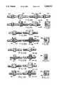
- FIGS. 8A, 9A, 10A and 11Aare enlarged top views of various embodiments of tubing suitable for use with a pump of this invention illustrating various fittings and placement of fittings relative to the tubing.
- FIGS. 8B, 9B, 10B and 11Bare partially sectioned side views of the tubing embodiments shown in FIGS. 8A, 9A, 10A and 11A, respectively.
- FIGS. 8C, 9C, 10C and 11Care end views of the tubing embodiments taken along the line 8C--8C of
- the pump 10 for a preferred embodiment of the inventionhas a precision rotary motor 12 which may for example be a DC stepper motor or other rotary motor for which the number of revolutions may be precisely controlled and which has minimal "run out” or "wobble".
- the motoris attached to a mounting plate 14 by a pair of screws 16 (FIG. 7).
- the rotatable shaft 18 of motor 12passes through a hole (not shown) in plate 14 and has a circular member 20 connected to the portion thereof extending through plate 14.
- Member 20has a circular projection 22 at its center for the preferred embodiment which extends over shaft 18 and is secured thereto by pressure fit, gluing or other suitable means which will not cause any eccentricity between shaft 18 and member 20.
- Member 20also has a plurality of shafts 24 evenly spaced about a circle having a center at shaft 18, each of the shafts 24 extending perpendicular to the member 20.
- a roller 26is rotatably mounted on each shaft 24 and is normally held in place by a cover plate 28 mounted over member 20 and rollers 24.
- Plate 28has an alignment pin (not shown) on its underside which mates with a corresponding hole 32 on projection 22 and is held in place by a screw 34 (FIG. 5) which passes through plate 28 and is screwed into a corresponding opening 36 in projection 22.
- Mounting plate 14also has a post 38 secured to and projecting from the front face thereof.
- a platen 40is mounted to pivot on post 38 between an inoperative position as shown in FIGS. 1 and 2 and an operative position as shown in FIGS. 3 and 5.
- Platen 40has a curved surface 42 with a radius that substantially matches the maximum radius from shaft 18 to the outer edge of rollers 26, but is slightly greater.
- Platen 40also has a pair of tube receiving grooves 44 and 46 (FIG. 2) each of which has a recess, 48 and 50, respectively, formed near the end thereof.
- Recesses 48 and 50are different in size and/or shape so that a fitting which fits in at least one of such recesses will not fit in the other recess.
- the recessesare preferably different in a sufficient number of ways that a fitting adapted to fit in each of the recesses will not fit or nest in the other recess.
- Platen 40also has a stop surface 52, a cam surface 54 with a detent notch or recess 55 formed near one end thereof, and a cam groove 61 formed in its underside. Stop surface 52 engages eccentric stop member 56 when platen 40 is moved to the operative position, thereby defining at least in part the size of the gap 57 between the rollers and platen surface 42.
- Cam surface 54coacts with a roller 58 on drive and latch member 60 and pin 59 on which roller 58 is mounted coacts with cam groove 61 to move platen 40 between its operative and inoperative positions as member 60 is rotated about a pivot post 62.
- Post 62is fitted in a hole formed at one end of web 64 (FIG. 7), the other end of web 64 passing over and being secured to a post 66 mounted to plate 14. Web 64 may be held on post 66 by for example a locking washer or other suitable means.
- Post 62has a spring 68 wrapped therearound which normally biases the post, and member 60 affixed thereto, in the counterclockwise direction (as viewed from the front in FIGS. 2 and 3).
- Web 64also has a post 70 formed slightly below post 62 to which one end of a spring 72 is connected, the other end of spring 72 being connected to a post 74 fixed to plate 14 and extending from the rear thereof.
- Member 60has a handle 76 which may be grasped between the thumb and forefinger of a user and used to pivot member 60, and thus platen 40, between the operative and inoperative positions.
- platen 40has a cover 78 mounted thereto.
- cover 78has a shaft 80 (FIG. 3) extending from the rear thereof which fits into a corresponding opening 82 in platen 40 and is secured to the back thereof by a lock washer or other suitable means so as to permit cover 78 to pivot relative to the platen about shaft 80.
- a spring 84 wrapped around shaft 80normally biases the cover in the counterclockwise direction to the position shown in FIG. 2. Rotation in a counterclockwise direction by cover 78 is limited by projection 86 extending from the rear of the cover contacting stop surface 88 of platen 40.
- cover 78has a surface 90 which coacts with a camming surface 92 of a cover 94 to pivot cover 78 to the operative position shown in FIG. 3 in which this cover covers recess 50.
- Cover 94has openings (not shown) in its rear side which coact with posts 96 secured to and extending from the front face of plate 14 to orient and mount the cover. A screw 98 passing through mating holes in the cover and mounting plate 14 secures cover 94 to the mounting plate. Cover 94 has a raised portion 100 which overlies cover 28 to protect motor 12 and is operative to cover recess 48 when the elements are in their operative position.
- eccentric stop member 56has a larger countersink or hole 102, a smaller countersink or hole 104 and a shaft 106 projecting from the rear end thereof, which shaft is slightly off center. There is a screw hole 107 in the rear center of shaft 106. Holes 102 and 104 are used, preferably with a suitable tool (not shown), to orient the stop. Preferably, the stop is initially oriented to its normal position (i.e. in a position where rotation in one direction results in an increase in the size of the gap and rotation in the opposite direction results in a decrease in the size of the gap). The different sizes of holes 102 and 104 permit a user to visually determine the proper orientation for the stop when assembling the device. Stop 56 is secured to plate 14 by a screw 108 which passes through plate 14 and into hole 107. Screw 108 may be loosened to permit rotation of the stop.
- pump 10also has a drain 109 to permit any accumulated fluid to drain from the pump so as to protect the motor, electrical connectors 113 for permitting desired electrical connections to be made to motor 12, and screws 115 which pass through corresponding holes 117 at the corners of plate 14 to permit the pump to be mounted to a frame, chassis or housing of equipment with which the pump is to be utilized.
- the final elements of the pumpare tubes 110 which are used in conjunction with pump 10.
- Each tube 110has a pair of fittings 112 and 114 with a precise length 116 of tubing therebetween, which tubing is to fit in the gap 57 between rollers 26 and platen surface 42.
- a portion 120 of tubingextends beyond each of the fittings 112 and 114.
- a connector fitting 122is provided which has a barb at one end fitting into the corresponding tube section 120 and a barb at its other end which fits into a length of extension tubing 124.
- tubing 116 and 120are formed of a silicon rubber or other suitable flexible material and each fixture 112-114 includes a block molded as part of the tubing.
- FIGS. 8A-8Cillustrate fittings which includes only blocks 130-132.
- the blocks 130 and 132are of different size and/or shape (preferably both) and are further shaped so as to fit in only a single one of the recesses 48 and 50 and to fully nest in such recess only for a single orientation of the block in the corresponding recess.
- the desired nesting of the fitting in only one orientationmay be accomplished by providing notches, projections, flanges or other structural variations on each block which mate with corresponding projections, indentations, ridges or the like on recesses 48 and 50 so as to permit the blocks to be inserted with only a single orientation.
- Examples of such shape variations in the blocksare shown in the various FIGS. 8A-11C.
- a flange 131is shown for the block 130 and a recess or indentation 133 is shown for the block 132.
- fittings formed of blocks 130,132 aloneWhile the desired single permitted orientation may be achieved with fittings formed of blocks 130,132 alone, such fittings have two potential disadvantages. First, the rubber tends to grip the walls of the corresponding recess, complicating insertion and withdrawal of the fittings, particularly for a relatively close fit. Since it is desirable that these operations be performed quickly, such sticking or grabbing is undesirable. Second, as is shown in FIGS. 4A and 4B, and as will be discussed in greater detail later, one function of the fittings is to inhibit movement from the inoperative to the operative position when either one of the fittings is not fully nested or seated. This assures that the pump cannot be operated unless tubing 110 has been inserted with the proper orientation.
- the single acceptable orientationalso assures that any seam in the tubing which is present for some tubing construction techniques is on a portion of the tube which is not contacted by either rollers 26 or platen 40 so that the existence of such seams does not impact the accuracy of fluid delivery from the pump.
- the blockage of platen movementis caused by any portion of the fitting projecting above the recess interacting with the cover for such recess to prevent the cover from passing over the recess and thus to prevent completion of movement from the inoperative to the operative position.
- silicon rubber and other flexible tubing materialsare relatively soft and it is therefore possible, when the blocks are formed of such material, for the blocks to deform and permit movement to the operative position even when a fitting is not fully nested. Therefore, if the configuration of FIGS. 8A-8C is to be utilized in accordance with preferred embodiments of the invention, the tubing, or at least the block portion thereof, must be formed of a harder rubber or other material which is not easily deformed. However, harder rubber tends to not work well as a peristaltic pumping medium.
- a hard plastic stopis preferably fitted over or attached to a portion of each block to form the fittings.
- The(as shown in FIGS. 9A-9C for 134 and 136) maybe snapped over tubing 116 and glued or otherwise secured to the block (130'-132') to form the fitting, or, as shown in FIGS. 10A-11C, the stop (138, 140 or 142, 144) may snap over the tubing and sandwich the corresponding block.
- FIG. 11Cillustrates one of the stops 144 having additional material on one side rendering the stop asymmetric so as to facilitate the fitting of the fixture embodying the stop in only one of the recesses and in only a single orientation.
- Other variationsincluding projections, recesses, flanges 145,147 and the like can be provided on the stops to facilitate single-orientation insertion in corresponding recesses.
- the stopsperform a number of functions. First, they protect the blocks which, as previously indicated, may be formed of a soft silicon rubber. Second, they have smooth surfaces which makes the fixtures easier and thus quicker to insert and remove into the corresponding recesses. Third, and perhaps most important, they assure that movement to an operative position for the pump cannot occur unless both fixtures are fully seated in their corresponding recess. This prevents incorrect volumes being delivered and possible wrong answers being given by the analyzer. If no volume is delivered, the system will give "No Result Detected" as an answer and the operator will know something is wrong.
- the first stepis to assure that eccentric stop 56 is properly oriented, with for example the larger hole 102 to the right and the holes horizontally aligned as shown in FIGS. 1-3 and 5.
- the next stepis to fit the gap tool in the space between rollers 26 and platen 40, to loosen screws and to then use handle 76 to rotate drive and latch member 60 in the clockwise direction to move the pump to its operative position. Since there is no tubing 110 in the pump at this time, seating of fixtures 112, 114 is not a factor.
- the position of the motor assembly including circular member 20 affixed to the end thereof,is then adjusted so that the rollers 26 press against the nondeformable tool to establish the desired gap 57 between the rollers and the platen. Screws 16 are then tightened.
- pump 10is precision designed, it is still possible that there may be slight variations in the radius of platen surface 42, in the rollers, in the shape of member 20 or a slight eccentricity in the mounting of this member so that the desired volume of fluid per revolution of the pump, for example 50 microliters per revolution, is not being achieved.
- the exact volume being pumped by the pumpcan be determined by putting a length of tubing 110 in pump 10, moving the pump to its operative position, running motor 12 for a known number of whole and/or fractional revolutions and measuring the volume of fluid pumped.
- screw 108may be loosened and eccentric stop 56 rotated slightly in the proper direction to either slightly enlarge or slightly reduce the size of the gap in order to effect a slight increase or decrease, respectively, in volume pumped. Several iterations of measurement and adjustment may be required until the pump is producing the exact volume desired within for example a few microliters.
- tubing 110having fittings 112 and 114 which are sized and shaped to fit and nest in recesses 48 and 50, respectively, is fitted with the section 116 in the space between rollers 26 and platen 40 with the pump in its inoperative position.
- tubing 116is properly oriented in the gap and handle 76 may be manually operated by a user to move drive and latch member 60 in the clockwise direction. This causes roller 58 on member 60 to ride up cam surface 54 of platen 40 and pin 59 to move in cam groove 61 pivoting the platen counterclockwise about post 38 toward its operative position.
- upper fixture 114clears the front upper surface of cover 94.
- Surface 90 of cover 78also engages cam surface 92 of cover 94 rotating cover 78 clockwise about pivot 80 against the force of spring 84. Since fixture 112 is also fully nested in recess 50 at this time, cover 78 passes over the fixture as a result of this rotation.
- roller 58 under pressure from spring 72drops into recess 55 in cam surface 54. This locks the pump in its operative position.
- tube section 116is pinched in gap 57 between rollers 26 and platen surface 42, with there being a precise quantity of fluid pinched in tubing 116 between each pair of adjacent rollers.
- motor 12is turned on to rotate rollers 26, the fluid trapped between each pair of adjacent rollers is moved with the rollers along tubing 116 from fitting 112 to fitting 114. This fluid forces fluid above or ahead of it in tubing 116 and into the tubing 120 and 124 therebeyond in the pump. As the fluid is pushed forward, a vacuum is created behind it in tubing 110 which draws additional fluid into the tubing. A pumping action is thus accomplished.
- the pumpis capable of providing precise quantities of fluid. For example, if the pump is calibrated to deliver 50 microliters for a complete revolution, 50/8 or 6.25 microliters are delivered by the pump for each 1/8 th revolution thereof, permitting precise delivery of fluid within the microliter range.
- tubing 110When the pumping operation from a given reservoir to an end location, for example a cuvette, has been completed, the appropriate ends of tubing 110 may be moved to a new reservoir and a new receiving receptacle or, to avoid contamination, the pump may be moved to its inoperative position and tubing 110 replaced before a new pumping operation is performed.
- handle 76is operated to move drive and latch member 60 in the counterclockwise direction. This permits roller 58 to disengage from recess 55 as the camming action of the roller against the walls of the recess overcome the spring force of spring 72.
- roller 58then rides down camming surface 42 under the action of spring 68, and pin 59 moves in camming groove 61, these movements combining to cam platen 42 to rotate in the clockwise direction to its inoperative position.
- cover 78is also returned to its inoperative position shown in FIG. 2 by the action of spring 84.
- a section of tubing 110When a section of tubing 110 is removed, it may either be discarded, sent to an appropriate location for cleaning or sterilization, which can normally be easily accomplished even with viscous fluids passing therethrough, or may be retained and reinserted in the pump the next time pumping is required from the same reservoir. For example, if reagents are being pumped, the same section of tubing may be used for pumping reagents into successive cuvettes. However, a section of tubing is slightly deformed when it is used in pump 10 and it is therefore important that the tubing be reinserted in the pump in the same precise orientation each time it is used in order to assure precise pumping. The coaction of fittings 112 and 114 with recesses 48 and 50 assure that this occurs in the manner previously described for each insertion of a given tubing section 110.
- a peristaltic pumpis thus provided which is easily used with all types of fluids, including viscous fluids, while still permitting precise quantities of fluid to be pumped. While the invention has been particularly described above with reference to a preferred embodiment for the pump and preferred embodiments for the various tubing sections, it is apparent that these embodiments are for purposes of illustration only and that other mechanisms known in the art could be utilized for operating the pump, for moving the pump between its operative and inoperative positions, for blocking movement from the inoperative to the operative position when a fixture is not fully seated and for performing the various adjustments.
Landscapes
- Engineering & Computer Science (AREA)
- Mechanical Engineering (AREA)
- General Engineering & Computer Science (AREA)
- Reciprocating Pumps (AREA)
Abstract
Description
Claims (16)
Priority Applications (3)
| Application Number | Priority Date | Filing Date | Title |
|---|---|---|---|
| US08/208,638US5388972A (en) | 1994-03-09 | 1994-03-09 | Peristaltic pump with removable tubing of precise length |
| AU27061/95AAU2706195A (en) | 1994-03-09 | 1995-03-09 | Peristaltic pump with removable tubing of precise length |
| PCT/US1995/003111WO1995024558A1 (en) | 1994-03-09 | 1995-03-09 | Peristaltic pump with removable tubing of precise length |
Applications Claiming Priority (1)
| Application Number | Priority Date | Filing Date | Title |
|---|---|---|---|
| US08/208,638US5388972A (en) | 1994-03-09 | 1994-03-09 | Peristaltic pump with removable tubing of precise length |
Publications (1)
| Publication Number | Publication Date |
|---|---|
| US5388972Atrue US5388972A (en) | 1995-02-14 |
Family
ID=22775390
Family Applications (1)
| Application Number | Title | Priority Date | Filing Date |
|---|---|---|---|
| US08/208,638Expired - LifetimeUS5388972A (en) | 1994-03-09 | 1994-03-09 | Peristaltic pump with removable tubing of precise length |
Country Status (3)
| Country | Link |
|---|---|
| US (1) | US5388972A (en) |
| AU (1) | AU2706195A (en) |
| WO (1) | WO1995024558A1 (en) |
Cited By (40)
| Publication number | Priority date | Publication date | Assignee | Title |
|---|---|---|---|---|
| US5549461A (en)* | 1995-07-21 | 1996-08-27 | Newland; George | Peristaltic pump attachment for slurry mixers |
| US5688112A (en)* | 1996-02-22 | 1997-11-18 | Garay; Thomas William | Rotor axis aligned tube and outlet for a peristaltic pump system |
| US5709539A (en)* | 1994-01-24 | 1998-01-20 | Varian Associates, Inc. | Pressing plate for linearized pulses from a peristaltic pump |
| GB2349431A (en)* | 1999-04-29 | 2000-11-01 | Watson Marlow Limited | Peristaltic pump having tube end location and seal means |
| US6537244B2 (en) | 1999-01-19 | 2003-03-25 | Assistive Technology Products, Inc. | Methods and apparatus for delivering fluids |
| US20050025647A1 (en)* | 2003-07-28 | 2005-02-03 | Ortega Victor J. | Quick loading peristaltic pump |
| US20050196307A1 (en)* | 2004-03-04 | 2005-09-08 | Cole-Parmer Instrument Company | Peristaltic pump |
| FR2871858A1 (en)* | 2004-06-22 | 2005-12-23 | Gilson Sas Soc Par Actions Sim | PERISTALTIC PUMP COMPRISING A LOCKABLE REMOVABLE CASSETTE |
| US20060002805A1 (en)* | 2004-06-30 | 2006-01-05 | Millipore Corporation | Peristaltic pump comprising members for locating a tube |
| US20060002799A1 (en)* | 2004-06-30 | 2006-01-05 | Millipore Corporation | Peristaltic pump comprising a bearing member and a counter-member adapted to cooperate with a tube |
| US20060083644A1 (en)* | 2004-10-12 | 2006-04-20 | Zumbrum Michael A | Dynamically tensioned peristaltic tubing pump |
| US20060177328A1 (en)* | 2005-02-10 | 2006-08-10 | Novasys Medical, Inc. | Peristaltic pump providing simplified loading and improved tubing kink resistance |
| US20080175734A1 (en)* | 2007-01-19 | 2008-07-24 | Cole-Parmer Instrument Company | Tube retainer system |
| US20090129944A1 (en)* | 2007-10-18 | 2009-05-21 | Cole-Palmer Instrument Company | Peristaltic pump |
| USD605286S1 (en) | 2007-01-19 | 2009-12-01 | Cole-Parmer Instrument Company | Tube retainer |
| US20100008793A1 (en)* | 2008-07-14 | 2010-01-14 | Blue-White Industries, Ltd. | Safety switch on a peristaltic pump |
| US20100049186A1 (en)* | 1997-08-13 | 2010-02-25 | Ams Research Corporation | Noninvasive devices, methods, and systems for shrinking of tissues |
| US20100114087A1 (en)* | 1998-02-19 | 2010-05-06 | Edwards Stuart D | Methods and devices for treating urinary incontinence |
| DE202010009736U1 (en) | 2009-07-15 | 2010-10-14 | Sartorius Stedim Biotech Gmbh | hose system |
| US20100301071A1 (en)* | 2007-12-05 | 2010-12-02 | Bunn-O-Matic Corporation | Peristaltic pump |
| US20110004161A1 (en)* | 2008-02-28 | 2011-01-06 | Jms Co., Ltd. | Injection device for semi-solidified nutritiional supplement |
| US20110171052A1 (en)* | 2007-09-27 | 2011-07-14 | Curlin Medical Inc. | Peristaltic pump assembly |
| US8177781B2 (en) | 2000-10-02 | 2012-05-15 | Novasys Medical, Inc. | Apparatus and methods for treating female urinary incontinence |
| US20130071272A1 (en)* | 2011-09-19 | 2013-03-21 | Jeffery T. Juretich | Peristaltic pump cassette and method of installing same |
| US8403927B1 (en) | 2012-04-05 | 2013-03-26 | William Bruce Shingleton | Vasectomy devices and methods |
| EP2592270A1 (en) | 2011-11-11 | 2013-05-15 | Connectors Verbindungstechnik AG | Pump hose for a peristaltic pump |
| US20130315763A1 (en)* | 2012-05-24 | 2013-11-28 | Cook Medical Technologies Llc | Peristaltic pump tubing securing system |
| US8740846B2 (en) | 1996-09-20 | 2014-06-03 | Verathon, Inc. | Treatment of tissue in sphincters, sinuses, and orifices |
| US9239049B2 (en)* | 2010-07-16 | 2016-01-19 | Boston Scientific Limited | Peristaltic pump having a self-closing occlusion bed |
| CN105697343A (en)* | 2016-02-19 | 2016-06-22 | 重庆杰恒蠕动泵有限公司 | Linear type fast-assembling peristaltic pump assembly |
| USD809909S1 (en) | 2013-03-15 | 2018-02-13 | Cook Medical Technologies Llc | Tubing clips |
| US20210372392A1 (en)* | 2020-05-26 | 2021-12-02 | Surpass Industry Co., Ltd. | Tube pump system |
| US11542937B2 (en) | 2019-02-15 | 2023-01-03 | Surpass Industry Co., Ltd. | Tube pump system and method for controlling the tube pump system |
| US11644026B2 (en)* | 2016-09-20 | 2023-05-09 | Medela Holding Ag | Device for suctioning bodily fluids and for supplying a substance |
| US11692540B2 (en) | 2017-11-08 | 2023-07-04 | Oina Vv Ab | Peristaltic pump |
| CN117462800A (en)* | 2023-12-27 | 2024-01-30 | 广州君霖医疗科技有限公司 | Catheter for pressurized atomizing equipment, peristaltic pump and pressurized atomizing equipment |
| EP4371916A1 (en)* | 2022-10-25 | 2024-05-22 | EAR Ritterbach GmbH & Co. KG | Conveying device for the directed conveyance of powdery substances and associated method |
| US12025117B2 (en) | 2020-05-26 | 2024-07-02 | Surpass Industry Co., Ltd. | Tube holding member and tube pump |
| US12163512B2 (en) | 2019-03-26 | 2024-12-10 | Grifols, S.A. | Method for calibrating a peristaltic pump, method for dispensing a quantity of liquid by means of a peristaltic pump and device for producing sterile preparations that can execute said methods |
| US12221956B2 (en) | 2020-01-31 | 2025-02-11 | Surpass Industry Co., Ltd. | Tube pump |
Citations (14)
| Publication number | Priority date | Publication date | Assignee | Title |
|---|---|---|---|---|
| US3841799A (en)* | 1971-08-23 | 1974-10-15 | East West Med Prod | Medical cassette pump |
| US3927955A (en)* | 1971-08-23 | 1975-12-23 | East West Medical Products Inc | Medical cassette pump |
| US4138205A (en)* | 1975-12-15 | 1979-02-06 | Hydro Pulse Corporation | Movable stator walls permitting access to tubing in peristaltic pump |
| US4179249A (en)* | 1977-12-07 | 1979-12-18 | Cole-Parmer Instrument Company | Quick loading peristaltic pump |
| US4187057A (en)* | 1978-01-11 | 1980-02-05 | Stewart-Naumann Laboratories, Inc. | Peristaltic infusion pump and disposable cassette for use therewith |
| US4493706A (en)* | 1982-08-12 | 1985-01-15 | American Hospital Supply Corporation | Linear peristaltic pumping apparatus and disposable casette therefor |
| US4519754A (en)* | 1981-09-29 | 1985-05-28 | Minick Dale E | Peristaltic pump having variable occlusion rates |
| US4527323A (en)* | 1983-10-11 | 1985-07-09 | Cole-Parmer Instrument Company | Tubing loading key |
| US4585399A (en)* | 1984-06-19 | 1986-04-29 | Richard Wolf Gmbh | Hose pump |
| US4673334A (en)* | 1984-05-25 | 1987-06-16 | Isco, Inc. | Peristaltic pump |
| US4886431A (en)* | 1988-04-29 | 1989-12-12 | Cole-Parmer Instrument Company | Peristaltic pump having independently adjustable cartridges |
| US4925376A (en)* | 1987-06-26 | 1990-05-15 | Tek-Aids, Inc. | Peristaltic pump with tube holding mechanism |
| US5082429A (en)* | 1990-08-28 | 1992-01-21 | Cole-Parmer Instrument Company | Peristaltic pump |
| US5213483A (en)* | 1991-06-19 | 1993-05-25 | Strato Medical Corporation | Peristaltic infusion pump with removable cassette and mechanically keyed tube set |
- 1994
- 1994-03-09USUS08/208,638patent/US5388972A/ennot_activeExpired - Lifetime
- 1995
- 1995-03-09AUAU27061/95Apatent/AU2706195A/ennot_activeAbandoned
- 1995-03-09WOPCT/US1995/003111patent/WO1995024558A1/enactiveApplication Filing
Patent Citations (14)
| Publication number | Priority date | Publication date | Assignee | Title |
|---|---|---|---|---|
| US3841799A (en)* | 1971-08-23 | 1974-10-15 | East West Med Prod | Medical cassette pump |
| US3927955A (en)* | 1971-08-23 | 1975-12-23 | East West Medical Products Inc | Medical cassette pump |
| US4138205A (en)* | 1975-12-15 | 1979-02-06 | Hydro Pulse Corporation | Movable stator walls permitting access to tubing in peristaltic pump |
| US4179249A (en)* | 1977-12-07 | 1979-12-18 | Cole-Parmer Instrument Company | Quick loading peristaltic pump |
| US4187057A (en)* | 1978-01-11 | 1980-02-05 | Stewart-Naumann Laboratories, Inc. | Peristaltic infusion pump and disposable cassette for use therewith |
| US4519754A (en)* | 1981-09-29 | 1985-05-28 | Minick Dale E | Peristaltic pump having variable occlusion rates |
| US4493706A (en)* | 1982-08-12 | 1985-01-15 | American Hospital Supply Corporation | Linear peristaltic pumping apparatus and disposable casette therefor |
| US4527323A (en)* | 1983-10-11 | 1985-07-09 | Cole-Parmer Instrument Company | Tubing loading key |
| US4673334A (en)* | 1984-05-25 | 1987-06-16 | Isco, Inc. | Peristaltic pump |
| US4585399A (en)* | 1984-06-19 | 1986-04-29 | Richard Wolf Gmbh | Hose pump |
| US4925376A (en)* | 1987-06-26 | 1990-05-15 | Tek-Aids, Inc. | Peristaltic pump with tube holding mechanism |
| US4886431A (en)* | 1988-04-29 | 1989-12-12 | Cole-Parmer Instrument Company | Peristaltic pump having independently adjustable cartridges |
| US5082429A (en)* | 1990-08-28 | 1992-01-21 | Cole-Parmer Instrument Company | Peristaltic pump |
| US5213483A (en)* | 1991-06-19 | 1993-05-25 | Strato Medical Corporation | Peristaltic infusion pump with removable cassette and mechanically keyed tube set |
Cited By (76)
| Publication number | Priority date | Publication date | Assignee | Title |
|---|---|---|---|---|
| US5709539A (en)* | 1994-01-24 | 1998-01-20 | Varian Associates, Inc. | Pressing plate for linearized pulses from a peristaltic pump |
| US5549461A (en)* | 1995-07-21 | 1996-08-27 | Newland; George | Peristaltic pump attachment for slurry mixers |
| US5688112A (en)* | 1996-02-22 | 1997-11-18 | Garay; Thomas William | Rotor axis aligned tube and outlet for a peristaltic pump system |
| US8740846B2 (en) | 1996-09-20 | 2014-06-03 | Verathon, Inc. | Treatment of tissue in sphincters, sinuses, and orifices |
| US20100049186A1 (en)* | 1997-08-13 | 2010-02-25 | Ams Research Corporation | Noninvasive devices, methods, and systems for shrinking of tissues |
| US9023031B2 (en) | 1997-08-13 | 2015-05-05 | Verathon Inc. | Noninvasive devices, methods, and systems for modifying tissues |
| US20100114087A1 (en)* | 1998-02-19 | 2010-05-06 | Edwards Stuart D | Methods and devices for treating urinary incontinence |
| US6537244B2 (en) | 1999-01-19 | 2003-03-25 | Assistive Technology Products, Inc. | Methods and apparatus for delivering fluids |
| US6752779B2 (en) | 1999-01-19 | 2004-06-22 | Assistive Technology Products, Inc. | Methods and apparatus for delivering fluids |
| GB2349431A (en)* | 1999-04-29 | 2000-11-01 | Watson Marlow Limited | Peristaltic pump having tube end location and seal means |
| US6494692B1 (en) | 1999-04-29 | 2002-12-17 | Watson-Marlow Limited | Peristaltic pumps |
| GB2349431B (en)* | 1999-04-29 | 2002-06-12 | Watson Marlow Ltd | Peristaltic pumps |
| EP1048848A1 (en)* | 1999-04-29 | 2000-11-02 | Watson-Marlow Limited | peristaltic pumps |
| US8465482B2 (en) | 2000-10-02 | 2013-06-18 | Verathon, Inc. | Apparatus and methods for treating female urinary incontinence |
| US8968284B2 (en) | 2000-10-02 | 2015-03-03 | Verathon Inc. | Apparatus and methods for treating female urinary incontinence |
| US8177781B2 (en) | 2000-10-02 | 2012-05-15 | Novasys Medical, Inc. | Apparatus and methods for treating female urinary incontinence |
| US7223079B2 (en) | 2003-07-28 | 2007-05-29 | The Coca-Cola Company | Quick loading peristaltic pump |
| US20050025647A1 (en)* | 2003-07-28 | 2005-02-03 | Ortega Victor J. | Quick loading peristaltic pump |
| US7478999B2 (en) | 2004-03-04 | 2009-01-20 | Cole-Parmer Instrument Company | Peristaltic pump |
| WO2005088130A1 (en)* | 2004-03-04 | 2005-09-22 | Cole-Parmer Instrument Company | Peristaltic pump |
| US20050196307A1 (en)* | 2004-03-04 | 2005-09-08 | Cole-Parmer Instrument Company | Peristaltic pump |
| US20070212240A1 (en)* | 2004-06-22 | 2007-09-13 | Claude Voyeux | Peristaltic pump with a removable cassette |
| FR2871858A1 (en)* | 2004-06-22 | 2005-12-23 | Gilson Sas Soc Par Actions Sim | PERISTALTIC PUMP COMPRISING A LOCKABLE REMOVABLE CASSETTE |
| WO2006008364A1 (en)* | 2004-06-22 | 2006-01-26 | Gilson Sas | Peristaltic pump comprising a lockable removable cassette |
| CN100381704C (en)* | 2004-06-30 | 2008-04-16 | 米利波尔公司 | Peristaltic pump including tubing retainer |
| US20060002799A1 (en)* | 2004-06-30 | 2006-01-05 | Millipore Corporation | Peristaltic pump comprising a bearing member and a counter-member adapted to cooperate with a tube |
| CN100554685C (en)* | 2004-06-30 | 2009-10-28 | 米利波尔公司 | Comprise and being used for and the pipe supporting member of cooperating and the peristaltic pump of counterpart |
| US7467932B2 (en)* | 2004-06-30 | 2008-12-23 | Millipore Corporation | Peristaltic pump comprising members for locating a tube |
| US20060002805A1 (en)* | 2004-06-30 | 2006-01-05 | Millipore Corporation | Peristaltic pump comprising members for locating a tube |
| US7878773B2 (en) | 2004-10-12 | 2011-02-01 | Maztech, Inc. | Dynamically tensioned peristaltic tubing pump |
| US20060083644A1 (en)* | 2004-10-12 | 2006-04-20 | Zumbrum Michael A | Dynamically tensioned peristaltic tubing pump |
| US20060177328A1 (en)* | 2005-02-10 | 2006-08-10 | Novasys Medical, Inc. | Peristaltic pump providing simplified loading and improved tubing kink resistance |
| US7722338B2 (en)* | 2005-02-10 | 2010-05-25 | Novasys Medical, Inc. | Peristaltic pump providing simplified loading and improved tubing kink resistance |
| USD605286S1 (en) | 2007-01-19 | 2009-12-01 | Cole-Parmer Instrument Company | Tube retainer |
| US20080175734A1 (en)* | 2007-01-19 | 2008-07-24 | Cole-Parmer Instrument Company | Tube retainer system |
| US7980835B2 (en) | 2007-01-19 | 2011-07-19 | Cole-Parmer Instrument Company | Tube retainer system for a peristaltic pump |
| US8257054B2 (en)* | 2007-09-27 | 2012-09-04 | Curlin Medical Inc. | Method of installing and removing a cassette from a pump body having a mounting pin |
| US20110171052A1 (en)* | 2007-09-27 | 2011-07-14 | Curlin Medical Inc. | Peristaltic pump assembly |
| US20090129944A1 (en)* | 2007-10-18 | 2009-05-21 | Cole-Palmer Instrument Company | Peristaltic pump |
| US8052399B2 (en) | 2007-10-18 | 2011-11-08 | Cole-Parmer Instrument Company | Peristaltic pump |
| US8550310B2 (en)* | 2007-12-05 | 2013-10-08 | Bunn-O-Matic Corporation | Peristaltic pump |
| CN101918714A (en)* | 2007-12-05 | 2010-12-15 | 班奥麦迪克公司 | Peristaltic pump |
| US20100301071A1 (en)* | 2007-12-05 | 2010-12-02 | Bunn-O-Matic Corporation | Peristaltic pump |
| US20110004161A1 (en)* | 2008-02-28 | 2011-01-06 | Jms Co., Ltd. | Injection device for semi-solidified nutritiional supplement |
| US8215931B2 (en) | 2008-07-14 | 2012-07-10 | Blue-White Industries, Ltd. | Safety switch on a peristaltic pump |
| US8418364B2 (en) | 2008-07-14 | 2013-04-16 | Blue-White Industries, Ltd. | Method of extending tubing life of a peristaltic pump |
| US20100008793A1 (en)* | 2008-07-14 | 2010-01-14 | Blue-White Industries, Ltd. | Safety switch on a peristaltic pump |
| US20100005655A1 (en)* | 2008-07-14 | 2010-01-14 | Blue-White Industries, Ltd. | Tubing installation tool for a peristaltic pump and methods of use |
| US20100008755A1 (en)* | 2008-07-14 | 2010-01-14 | Blue-White Industries, Ltd. | Method of extending tubing life of a peristaltic pump |
| DE102009033401B3 (en)* | 2009-07-15 | 2011-04-21 | Sartorius Stedim Biotech Gmbh | hose system |
| US10267304B2 (en) | 2009-07-15 | 2019-04-23 | Sartorius Stedim Biotech Gmbh | Hose system |
| US20110014075A1 (en)* | 2009-07-15 | 2011-01-20 | Sartorius Stedim Biotech Gmbh | Hose system |
| DE202010009736U1 (en) | 2009-07-15 | 2010-10-14 | Sartorius Stedim Biotech Gmbh | hose system |
| US9239049B2 (en)* | 2010-07-16 | 2016-01-19 | Boston Scientific Limited | Peristaltic pump having a self-closing occlusion bed |
| US20130071272A1 (en)* | 2011-09-19 | 2013-03-21 | Jeffery T. Juretich | Peristaltic pump cassette and method of installing same |
| US8459968B2 (en)* | 2011-09-19 | 2013-06-11 | Curlin Medical Inc. | Peristaltic pump cassette and method of installing same |
| EP2592270A1 (en) | 2011-11-11 | 2013-05-15 | Connectors Verbindungstechnik AG | Pump hose for a peristaltic pump |
| US9086178B2 (en) | 2011-11-11 | 2015-07-21 | Connectors Verbindungstechnik Ag | Pump hose for a peristaltic pump |
| WO2013068206A1 (en) | 2011-11-11 | 2013-05-16 | Connectors Verbindungstechnik Ag | Pump hose for a peristaltic pump |
| US8403927B1 (en) | 2012-04-05 | 2013-03-26 | William Bruce Shingleton | Vasectomy devices and methods |
| US20130315763A1 (en)* | 2012-05-24 | 2013-11-28 | Cook Medical Technologies Llc | Peristaltic pump tubing securing system |
| US10113542B2 (en)* | 2012-05-24 | 2018-10-30 | Cook Medical Technologies Llc | Peristaltic pump tubing securing system |
| USD809909S1 (en) | 2013-03-15 | 2018-02-13 | Cook Medical Technologies Llc | Tubing clips |
| CN105697343A (en)* | 2016-02-19 | 2016-06-22 | 重庆杰恒蠕动泵有限公司 | Linear type fast-assembling peristaltic pump assembly |
| US11644026B2 (en)* | 2016-09-20 | 2023-05-09 | Medela Holding Ag | Device for suctioning bodily fluids and for supplying a substance |
| US12320348B2 (en) | 2017-11-08 | 2025-06-03 | Oina Vv Ab | Peristaltic pump |
| US11692540B2 (en) | 2017-11-08 | 2023-07-04 | Oina Vv Ab | Peristaltic pump |
| US11542937B2 (en) | 2019-02-15 | 2023-01-03 | Surpass Industry Co., Ltd. | Tube pump system and method for controlling the tube pump system |
| US12163512B2 (en) | 2019-03-26 | 2024-12-10 | Grifols, S.A. | Method for calibrating a peristaltic pump, method for dispensing a quantity of liquid by means of a peristaltic pump and device for producing sterile preparations that can execute said methods |
| US12221956B2 (en) | 2020-01-31 | 2025-02-11 | Surpass Industry Co., Ltd. | Tube pump |
| JP2021188522A (en)* | 2020-05-26 | 2021-12-13 | サーパス工業株式会社 | Tube pump system |
| US12018670B2 (en)* | 2020-05-26 | 2024-06-25 | Surpass Industry Co., Ltd. | Tube pump system |
| US12025117B2 (en) | 2020-05-26 | 2024-07-02 | Surpass Industry Co., Ltd. | Tube holding member and tube pump |
| US20210372392A1 (en)* | 2020-05-26 | 2021-12-02 | Surpass Industry Co., Ltd. | Tube pump system |
| EP4371916A1 (en)* | 2022-10-25 | 2024-05-22 | EAR Ritterbach GmbH & Co. KG | Conveying device for the directed conveyance of powdery substances and associated method |
| CN117462800A (en)* | 2023-12-27 | 2024-01-30 | 广州君霖医疗科技有限公司 | Catheter for pressurized atomizing equipment, peristaltic pump and pressurized atomizing equipment |
Also Published As
| Publication number | Publication date |
|---|---|
| WO1995024558A1 (en) | 1995-09-14 |
| AU2706195A (en) | 1995-09-25 |
Similar Documents
| Publication | Publication Date | Title |
|---|---|---|
| US5388972A (en) | Peristaltic pump with removable tubing of precise length | |
| EP3226933B1 (en) | Pump cassettes with flow stop and infusion pump systems | |
| US5340290A (en) | Double feed peristaltic pump | |
| US12403242B2 (en) | Pump systems with positioning features | |
| US5213483A (en) | Peristaltic infusion pump with removable cassette and mechanically keyed tube set | |
| US5927956A (en) | Peristaltic pump tubing system with latching cassette | |
| US6457609B1 (en) | Cartridge dispenser including drive for dynamic mixer | |
| EP3263898B1 (en) | Peristaltic pumphead and methods for assembly thereof | |
| CA2697577C (en) | Peristaltic pump and removable cassette therefor | |
| US5246354A (en) | Valveless metering pump with reciprocating, rotating piston | |
| DE112008003624B4 (en) | Hydraulic machine and fan drive device | |
| US10293102B2 (en) | Pump cassettes with piston and infusion pump systems | |
| JPH04272485A (en) | Valveless positive motion displacement metering pump and actuating method thereof | |
| US6234771B1 (en) | Precision pumping device | |
| GB2076476A (en) | Peristaltic fluid-machines | |
| EP0591449B1 (en) | Apparatus for calibrating a multiple port pump | |
| US6884231B1 (en) | Dual chambered fluid displacement apparatus | |
| US20050023291A1 (en) | Peristaltic precision metering device, system and method of use thereof | |
| CN117491443A (en) | Sample analysis equipment and kits | |
| CN216200822U (en) | Rotary valve | |
| EP0144240B1 (en) | Precision reagent metering and delivery device | |
| WO2000057173A1 (en) | Pulse damper |
Legal Events
| Date | Code | Title | Description |
|---|---|---|---|
| AS | Assignment | Owner name:MEDICAL LABORATORY AUTOMATION, INC., NEW YORK Free format text:ASSIGNMENT OF ASSIGNORS INTEREST;ASSIGNORS:CALHOUN, JEFFREY E.;WICKHAM, TIMOTHY F.;REEL/FRAME:006906/0056 Effective date:19940215 | |
| FEPP | Fee payment procedure | Free format text:PAYOR NUMBER ASSIGNED (ORIGINAL EVENT CODE: ASPN); ENTITY STATUS OF PATENT OWNER: LARGE ENTITY | |
| STCF | Information on status: patent grant | Free format text:PATENTED CASE | |
| REMI | Maintenance fee reminder mailed | ||
| FEPP | Fee payment procedure | Free format text:PAT HLDR NO LONGER CLAIMS SMALL ENT STAT AS SMALL BUSINESS (ORIGINAL EVENT CODE: LSM2); ENTITY STATUS OF PATENT OWNER: LARGE ENTITY | |
| FPAY | Fee payment | Year of fee payment:4 | |
| SULP | Surcharge for late payment | ||
| FEPP | Fee payment procedure | Free format text:PAYER NUMBER DE-ASSIGNED (ORIGINAL EVENT CODE: RMPN); ENTITY STATUS OF PATENT OWNER: LARGE ENTITY Free format text:PAYOR NUMBER ASSIGNED (ORIGINAL EVENT CODE: ASPN); ENTITY STATUS OF PATENT OWNER: LARGE ENTITY | |
| FEPP | Fee payment procedure | Free format text:PAYER NUMBER DE-ASSIGNED (ORIGINAL EVENT CODE: RMPN); ENTITY STATUS OF PATENT OWNER: LARGE ENTITY Free format text:PAYOR NUMBER ASSIGNED (ORIGINAL EVENT CODE: ASPN); ENTITY STATUS OF PATENT OWNER: LARGE ENTITY | |
| FPAY | Fee payment | Year of fee payment:8 | |
| SULP | Surcharge for late payment | Year of fee payment:7 | |
| REMI | Maintenance fee reminder mailed | ||
| FPAY | Fee payment | Year of fee payment:12 | |
| SULP | Surcharge for late payment | Year of fee payment:11 | |
| FEPP | Fee payment procedure | Free format text:PAYER NUMBER DE-ASSIGNED (ORIGINAL EVENT CODE: RMPN); ENTITY STATUS OF PATENT OWNER: LARGE ENTITY Free format text:PAYOR NUMBER ASSIGNED (ORIGINAL EVENT CODE: ASPN); ENTITY STATUS OF PATENT OWNER: LARGE ENTITY |