US5388680A - Coin handling system with an improved coin chute - Google Patents
Coin handling system with an improved coin chuteDownload PDFInfo
- Publication number
- US5388680A US5388680AUS07/841,379US84137992AUS5388680AUS 5388680 AUS5388680 AUS 5388680AUS 84137992 AUS84137992 AUS 84137992AUS 5388680 AUS5388680 AUS 5388680A
- Authority
- US
- United States
- Prior art keywords
- chute
- coin
- pieces
- foreign object
- backwall
- Prior art date
- Legal status (The legal status is an assumption and is not a legal conclusion. Google has not performed a legal analysis and makes no representation as to the accuracy of the status listed.)
- Expired - Fee Related
Links
Images
Classifications
- G—PHYSICS
- G07—CHECKING-DEVICES
- G07F—COIN-FREED OR LIKE APPARATUS
- G07F1/00—Coin inlet arrangements; Coins specially adapted to operate coin-freed mechanisms
- G07F1/04—Coin chutes
- G07F1/041—Coin chutes with means, other than for testing currency, for dealing with inserted foreign matter, e.g. "stuffing", "stringing" or "salting"
- G07F1/045—Coin chutes with means, other than for testing currency, for dealing with inserted foreign matter, e.g. "stuffing", "stringing" or "salting" the foreign matter being in the form of liquids
Definitions
- This inventionrelates in general to the field of coin handling systems and more particularly to a coin handling system having an improved coin chute for use in coin operated machines.
- Jammed coin handlerspresent a serious problem for coin operated machines. For example, it is estimated that 80% of service calls for pay telephones are to repair jammed coin handlers within the telephones. In pay telephones, the coin handlers are typically jammed by thieves who stuff matchbooks, partially inflated balloons or other foreign objects into the coin chute. These foreign objects cause the coin chute to fill up with coins as pay telephone callers unsuccessfully attempt to use the telephone. The thief retrieves these coins by pushing a coat hanger, a dipstick or other similar object into the coin chute, thereby forcing the coins through an adjacent coin validator and into a coin return slot.
- the thiefretrieves the coins by inserting a coat hanger, a dipstick or another similar elongated object with a hook-type device at its end into the coin chute and drawing the lodged coins out through the coin slot with the hook-type device.
- hook-type objectsWhen hook-type objects are forced into a coin chute, they often become caught in the chute. This may lead to breakage of the chute if the thief attempts to forcibly retrieve the caught foreign object.
- a needhas arisen for a coin handling system that prevents the intentional or accidental jamming of a coin operated machine and that safeguards the machine from potential damage from attempts to jam the machine. Further, there is a need for a coin handling system that prevents hook-type devices from becoming caught on coin chutes, thereby preventing damage to the coin chute that would occur if attempts were made to forcibly retrieve a caught hook-type device.
- a coin handling systemthat prevents the jamming of foreign objects and coins in coin operated machines and prevents foreign objects forced into the machines from entering and damaging coin validators and other internal mechanisms of the machines.
- the coin handling system of the present inventioncomprises a coin chute that can be divided into two separate pieces to clear coins and other objects lodged in the chute.
- the coin chutecan easily be cleared by a "sweep and clear" mechanism.
- a coin release lever outside the machineWhen actuated, the coin chute rotates from its biased rest position, usually above the entry to an electronic coin validator, to a position above a trash and coin return chute. When it is at this second position, the coin chute separates, releasing the lodged coins and foreign objects.
- An important technical advantage of the present inventionis that it prevents theft by intentional jamming of coin operated machines. If foreign material is lodged into the chute by a thief to block the passage of and to collect coins inserted by later users, the foreign material can be easily cleared by activating the "sweep and clear" operation of the invention. No coins will accumulate for the thief.
- a further technical advantage of the present inventionis that activation of the "sweep and clear" operation also activates a clearing mechanism in the coin validator so that the coin validator can be simultaneously cleared.
- ridgesare integrated in the inner side surfaces of the coin chute. These ridges tend to trap foreign material in the upper portions of the chute, preventing the foreign material from traveling further along the coin path. These ridges also prevent wet coins from sticking to the inner surfaces of the coin chute.
- the coin chutemay comprise a multidirectional shape such that coins or other objects attempting to pass through the chute must change directions and consequently impact a wall of the chute.
- the multidirectional shapecomprises an L-shape such that foreign object cannot be guided through the chute without impacting a back wall of the chute near the single bend in the chute.
- the back end of the coin chutemay comprise several slots.
- the interior rear edge of one of the two pieces that forms the chuteis bevelled.
- the chuteseparates and causes the object to leave the chute rather than travel down the chute into the internal mechanisms disposed below the chute.
- ridgesare integrated into the backwall of the chute. These ridges inhibit downward movement of foreign objects that are forced into the coin chutes and against the coin chute backwall.
- the chute pieces forming the coin chuteare provided with external bevelled surfaces. If a foreign object with a hook at its end is forced into the chute, the chute initially separates as the foreign object impacts the previously described internal bevelled surface, causing the foreign object to harmlessly move out of the chute. Then, if the thief attempts to withdraw the foreign object, the foreign object impacts the external bevelled surface, causing the chute to reopen and allowing the thief to remove the object. Because of the external bevelled surface, no damage is done to the chute as the foreign object does not become hooked to any outside edge of the coin chute.
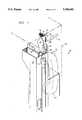
- FIG. 1is a three dimensional view showing the location and position of a coin handling system in a pay telephone
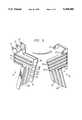
- FIG. 2is an exploded view of one embodiment of the coin chute used in the present invention.
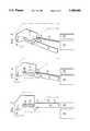
- FIG. 3, 4 and 5are sequential diagrams that illustrate the operation of the invention's "sweep and clear" mechanism
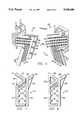
- FIG. 6is an exploded view of a coin chute constructed in accordance with another embodiment of the invention.
- FIG. 7is a sectional view taken generally along lines 7--7 of FIG. 6;
- FIGS. 8 through 11are further sectional views of chutes constructed in accordance with further embodiments of the invention.
- FIG. 12is a view of the FIG. 7 chute, illustrating operation of the bevelled surface feature of the invention when a hook-type object is forced into the chute.
- FIG. 1shows an embodiment of the present invention as it may be used in a generally indicated pay telephone 10.
- Pay telephone 10comprises a receiver 11 which, when not in use, is placed on a cradle 12.
- Cradle 12is mounted to the outside of a chassis 13.
- a coin release lever 14is pivotally connected to the outside of chassis 13.
- Coin release lever 14is connected by a linkage (not shown) to a coin chute 15.
- the top of coin chute 15is pivotally connected to a bracket 16, which is mounted on the inside of chassis 13.
- a pivot pin 17is used to connect coin chute 15 to bracket 16.
- a first biasing spring 18 and a second biasing spring 19are wound around pivot pin 17.
- a first coin slot 20is formed in bracket 16.
- a second coin slot 21is aligned with first coin slot 20 when the coin chute 15 is in a rest position and forms the entry to coin chute 15.
- Coin chute 15comprises a first chute piece 22 and a second chute piece 23. First and second chute pieces 22 and 23 are biased together by first biasing spring 18. Coin chute 15 is biased into a vertical position by second biasing spring 19. When in its vertical position, coin chute 15 is disposed directly above the entry to a coin validator 24, which is also mounted on the bracket 16.
- Coin validator 24may comprise, for example, an "MS16" model coin validator manufactured by Mars Electronics. Coin validator 24 functions to electronically detect counterfeit coins as well as to determine the value of coins inserted by a patron. It should be understood that while the preferred embodiment comprises an electronic coin validator, any type of coin validator may be used to determine the value of coins deposited including those functioning mechanically or optically.
- Coin validator 24selectively routes coins to a coin box (not shown) or a coin return box 26.
- the internal mechanisms of coin validator 24can be easily damaged by foreign objects forced through coin validator 24.
- a trash and coin release chute 25is positioned adjacent to coin validator 24, such that coin chute 15 can be rotated from its position above coin validator 24 to a position in which its lower end is above trash and coin return chute 25.
- At the lower end of trash and coin return chute 25is a coin return box 26, from which a telephone user can retrieve coins and foreign objects that have been jammed in and dislodged from coin chute 15.
- FIG. 2is an exploded view of coin chute 15, showing first coin chute piece 22 and second coin chute piece 23.
- Both chute piece 22 and chute piece 23have pivot pin holders 27 formed at their upper edges. Pivot pin 17 fits in pivot pin holders 27, pivotally coupling first chute piece 22 to second chute piece 23. Both first chute piece 22 and second chute piece 23 also have ridges 28 formed on their interior surfaces.
- Second chute piece 23has a bevelled edge 29 formed on its rear edge. Second chute piece 23 also contains slots 30 formed in and generally shown on the rear edge.
- a stop plate 31is formed near the center of the front edge of chute piece 22.
- the phone userWhen the pay telephone 10 is used normally, the phone user inserts a coin in coin slot 20, which is aligned with coin slot 21 at the entry to coin chute 15. The coin rolls through coin chute 15 and enters coin validator 24, which is directly beneath coin chute 15 when coin chute 15 is in its normal rest position. The coin validator then examines the coin to determine whether it is sufficient to allow the caller to use the phone.
- FIGS. 3, 4 and 5are sequential diagrams illustrating the "sweep and clear" operation.
- FIG. 3shows a front view of coin chute 15 in its biased vertical rest position in which the bottom end of coin chute 15 is directly above the entry to coin validator 24.
- Coin chute 15is biased in this rest position by second biasing spring 19.
- First coin chute piece 22 and second coin chute piece 23are biased together to form coin chute 15 by first biasing spring 18.
- coin release lever 14To activate the sweep and clear operation, the user of pay telephone 10 depresses coin release lever 14. This causes the coin chute 15, which is pivotally connected at its top to bracket 16, to rotate from its rest position to a second position in which the exit end of coin chute 15 is above the trash and coin return chute 25 as shown in FIG. 4. When the coin chute 15 reaches this second position, stop plate 31 of first chute piece 22 engages a stop 32 fixed with respect to bracket 16 which prevents first chute piece 22 from further rotation. Second chute piece 23 is unhindered by the stop 32 and rotates away from first chute piece 22 as shown in FIG. 11. When the chute 15 is in this divided position, coins or foreign matter jammed in coin chute 15 are dislodged into the trash and coin return chute 25. When the telephone user releases coin release lever 14, chute 15 closes and rotates back into the biased rest position shown in FIG. 10. Coin release lever 14 is connected to and controls the movement of coin chute 15 by means of a suitable linkage (not shown).
- coin validator 24may itself comprise a clearing system operable to clear foreign objects trapped in the coin path of coin validator 24.
- the entrance to coin validator 24may comprise hinged sidewalls (not shown) to allow for the clearing of foreign objects that somehow become jammed in coin validator 24.
- any clearing features of coin validator 24can be actuated after coin chute 15 is moved to the position shown in FIG. 3. Accordingly, any foreign objects jammed in coin chute 15 as well as any foreign objects jammed in coin validator 24 may be-cleared simultaneously.
- coin chute 15comprises a multidirectional shape such that coins passing through chute 15 are forced to change directions during their passage. This shape makes it difficult to negotiate foreign objects such as dipsticks, coat hangers or the like through chute 15 as any such objects will necessarily be forced into a wall of chute 15.
- Chute 15is shown comprising an L shape, however, chute 15 may comprise a variety of arcuate or other multidirectional shapes.
- the general L shape of chute 15is shown solely for the purpose of teaching the present invention and should not be construed to limit the scope of the present invention to this or any specific embodiment.
- An additional technical advantage of the coin handling system of the present inventioninheres in the fact that the back edge of chute piece 23 is bevelled.
- a foreign objectlike a coat hanger or dipstick is forced into coin chute 15, due to the multidirectional shape discussed previously, it impacts the bevelled edge 29, causing chute piece 23 to separate from chute piece 22.
- the coat hanger or other objectis forced to leave coin chute 15 and prevented from going further into coin chute 15 or into coin validator 24.
- the slots 30located in the back edge of chute piece 23.
- the slots 30cause the foreign object to protrude through one of the slots and prevent it from going further into chute 15 or into coin validator 24.
- a third aspect of the present inventionis the set of ridges 28 formed on the inside surface of chute piece 22 and chute piece 23. Ridges 28 function to trap foreign material in the upper portion of chute 15, preventing such foreign material from passing through chute 15 until the "sweep and clear" operation of the present invention is implemented. Additionally, ridges 28 reduce the surface area of chute 15 that comes into contact with coins and, as a result, prevent wet coins from sticking to the insides of coin chute 15.
- chute 15can be easily cleared by the invention's "sweep and clear" operation.
- coin chute 15can be first moved and then separated into two pieces, allowing the matchbook or other objects to fall out into trash and coin return chute 25. As a result, coins do not accumulate for thieves. The phone 10 is then ready for normal operation.
- FIG. 6is an exploded view similar to FIG. 2 of a coin chute 115 constructed in accordance with an alternative embodiment of the invention.
- Coin chute 115is comprised of a first coin chute piece 122 and a second coin chute piece 123.
- chute pieces 122 and 123each comprise the pivot pin holders 27 and the ridges 28 on their interior surfaces.
- First chute piece 122also comprises the stop plate 31.
- Second chute piece 123comprises a backwall 140.
- the backwall 140extends from the rest of the second chute piece 123 at an obtuse angle, forming an internal bevelled surface 129.
- chute piece 123does not comprise the slots 30 on the backwall 140.
- a plurality of ridges 130are formed on the backwall 140. In operation, when foreign objects like coat hangers are forced into the coin chute 115, the foreign objects impact the ridges 130 on the backwall 140. The ridges 130 thereby obstruct and inhibit downward movement of the foreign objects.
- the ridges 130may be replaced by a plurality of grooves (not shown) formed into the backwall 140.
- the ridges 130may be replaced by a plurality of grooves (not shown) formed into the backwall 140.
- the ridgesengage the foreign objects and thereby inhibit their downward movement.
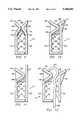
- FIG. 7is a cross-sectional view of coin chute 115 taken generally along the lines 7--7 shown in FIG. 6, illustrating the additional external bevelled surface feature of the invention.
- the chute pieces 122 and 123are shown in FIG. 7 as they are biased together.
- first chute piece 122comprises a first wing member 141
- second chute piece 123comprises a second wing member 142. Note that the wing members 141 and 142 are not visible in the view of the chute pieces 122 and 123 shown in FIG. 6 because of the particular angle at which the chute pieces 122 and 123 are illustrated.
- the second wing member 142is integral with the second chute piece 123 along the entire length of the backwall 140.
- the second wing member 142extends from the backwall 140 at an angle, thereby forming an external bevelled surface 144.
- the connection of the second wing member 142 to the backwall 140may be strengthened or supported by, for example, a plurality of vertically spaced support ribs 146, which extend perpendicular to the backwall 140 across the space between the backwall 140 and the wing member 142 and are integral with the backwall 140 and the wing member 142.
- the first chute piece 122comprises the first wing member 141, which extends at an angle from the rest of the chute piece 122, forming a second external bevelled surface 148. Like the second wing member 142, the connection of the first wing member 141 to the rest of the chute piece 122 may be strengthened or supported by a set of support ribs 150.
- the external bevelled surface feature of the present inventionis apparent. It should be noted that the external bevelled surfaces 144 and 148 are integral with the exterior of the chute 115. The bevelled surfaces 144 and 148 are not exterior to the coin operated machine, in which the chute 115 is mounted.
- the bevelled surfaces 144 and 148allow foreign objects with hook-like features that have been forced to move through the coin chute 115 to reenter without becoming caught on one of the edges of the chute 115. The foreign object can thus be removed without breaking or otherwise damaging the chute 115.
- Support ribs 146 and 150may be omitted if the wing members 141 and 142 are relatively small in size.
- the wing members 141 and 142should be sufficiently large, however, so that commonly used hooks on the foreign objects do not become caught on the far edges of the wing members 141 and 142.
- the size of the wing members 141 and 142may, however, have to be restricted because of space limitations within the coin operated machine.
- FIGS. 8 through 11show cross-sectional views of coin chutes similar to chute 115 constructed in accordance with alternative embodiments. The views shown in FIGS. 8 through 11 are included for the purpose of showing various alternative designs for the external bevelled edge feature of the invention. It should be noted that like reference characters denote like parts in all figures.
- a coin chuteindicated generally at 215, is shown comprising chute pieces 222 and 223.
- the rear portion of the chute piece 223resembles a triangle in the cross-sectional view.
- One side of the triangleforms an internal bevelled surface 229.
- a second side of the triangleforms an external bevelled surface 244.
- the third side of the triangleis aligned and integral with the exterior side wall of the chute piece 223.
- the triangular portionmay comprise a hollow portion 254 formed near its center. Ridges 230, similar to the ridges 130 shown in FIG. 6 are formed on the bevelled surface 229.
- the first chute piece 222is similar to the first chute piece 122 shown in FIG. 7.
- the first chute piece 222comprises a first wing member 241, which extends outwardly from the rest of the chute piece 222, forming an external bevelled surface 248.
- the connection of the first wing member 241 to the rest of the first chute piece 222may be supported by a plurality of support ribs 250, which are similar to the ribs 150 shown in FIG. 7.
- a technical advantage of the second chute piece 223is that it is particularly resistant to breakage as the external bevelled surface 244 is continuously supported by the triangular structure.
- the coin chute 315 shown in FIG. 9comprises first and second chute pieces 322 and 323.
- the second chute piece 323comprises an angled backwall portion 340, forming an internal bevelled surface 329.
- first chute piece 322comprises an angled backwall portion 352, forming an internal bevelled surface 343.
- the backwall portions 340 and 352join to form a complete backwall for the chute 315.
- each of the backwall portions 340 and 352may comprise one-half of the complete backwall for the chute 315.
- the proportion of the complete backwall comprised by each of the backwall portions 340 and 352may be varied.
- the backwall portion 340may be made larger than backwall portion 352 and may therefore comprise more than one-half of the complete backwall. Ridges 330 and 331 are formed on the backwall portions 340 and 352, respectively.
- the wing members 341 and 342are integral with the backwall portions 352 and 340, respectively.
- the wing members 341 and 342each project at an angle, respectively forming external bevelled surfaces 348 and 344.
- Support ribs 346 and 350help support the wing members 342 and 341, respectively.
- a technical advantage of the coin chute 315is that it permits smooth separation of the chute pieces 322 and 323 when either the internal bevelled surfaces 329 and 343 or the external bevelled surfaces 344 and 348 are impacted by a foreign object.
- the coin chute 415 shown in FIG. 10comprises first and second chute pieces 422 and 423.
- the second chute piece 423is similar to the second chute piece 123 shown in FIG. 7. It comprises an angled backwall 440, forming an internal bevelled surface 429.
- a wing member 442extends outwardly at an angle from the backwall 440, forming an external bevelled surface 444.
- a plurality of support ribs 446helps support the connection of the wing member 442 to the backwall 440.
- Ridges 430similar to ridges 130 shown in FIG. 6, are formed on the backwall 440.
- the coin chute piece 422comprises a rear portion 452, which extends from the rest of chute piece 422 in a direction toward the chute piece 423.
- Rear portion 452runs generally parallel to and fits behind the wing member 442 of the chute piece 423 when the chute 415 is in a closed position.
- Extending in a direction away from the rear portion 452is a wing member 441, forming an external bevelled surface 448.
- the connection of the wing member 441 to the rear portion 452may be supported by a plurality of support ribs 450.
- a technical advantage of the chute 415is that it is particularly effective in preventing coins from inadvertently causing the separation of the chute pieces 422 and 423.
- FIG. 11shows a further alternative coin chute 515 comprising first and second chute pieces 522 and 523.
- the second chute piece 523is similar to the second chute piece 123 shown in FIG. 7.
- Chute piece 523comprises a backwall 540 extending from the rest of the chute piece 523 at an angle, forming an internal bevelled surface 529.
- a wing member 542extends at an angle from the backwall 540, forming an external bevelled surface 544.
- a plurality of support ribs 546help support the connection of the wing members 542 to the backwall 540.
- Ridges 530similar to the ridges 130 shown in FIG. 6, are formed on the backwall 540.
- the first chute piece 522comprises an end portion 541 that is integral with and extends from the rest of the chute piece 522 without bending.
- a technical advantage of coin chute 515is that it can be used in coin operated machines that have internal space constraints that prevent use of two bent chute pieces.
- FIGS. 7 through 11are included herein for the purpose of teaching various technical advantages of the present invention. The presentation of these embodiments should not be construed to limit the scope of the present invention to any specific embodiment.
- FIG. 12illustrates the interaction of a hook-type object with coin chute 115, which was previously described with reference to FIG. 7. If an elongated foreign object 600 having a hook-end 602 is forced into coin chute 115, the chute pieces 122 and 123 separate upon impact of the hook-end 602 against the internal bevelled edge 129. The foreign object 600 thus travels harmlessly through the separated chute 115.
- the external bevelled surfaces 144 and 148prevent the hook-end 602 from becoming caught on a part of one of the chute pieces 122 or 123.
- the thiefmay cause damage to the chute 115 if he forcibly attempts to retrieve a foreign object 600 that has become caught on one of the chute pieces 122 or 123.
- the phonebecomes inoperable for future users, who will probably also be unable to withdraw the foreign object 600. The phone will thus require servicing.
- the external bevelled surfaces 144 and 148reduce the possibility of having the hook-end 602 of the foreign object 600 becoming caught on the outside of the chute pieces 122 and 123. If the hook-end 602 is forced against the outside of the coin chute 115, the bevelled surfaces 144 and 148 will cause the chute 115 to separate, allowing continued movement and eventual removal of the foreign object 600. The foreign object 600 can thus be removed without causing damage to the chute 115.
Landscapes
- Physics & Mathematics (AREA)
- General Physics & Mathematics (AREA)
- Control Of Vending Devices And Auxiliary Devices For Vending Devices (AREA)
Abstract
Description
Claims (25)
Priority Applications (2)
| Application Number | Priority Date | Filing Date | Title |
|---|---|---|---|
| US07/841,379US5388680A (en) | 1990-10-09 | 1992-02-25 | Coin handling system with an improved coin chute |
| US08/200,481US5441138A (en) | 1990-10-09 | 1994-02-23 | Coin handling system with an improved coin chute |
Applications Claiming Priority (2)
| Application Number | Priority Date | Filing Date | Title |
|---|---|---|---|
| US07/594,272US5090548A (en) | 1990-10-09 | 1990-10-09 | Coin handling system |
| US07/841,379US5388680A (en) | 1990-10-09 | 1992-02-25 | Coin handling system with an improved coin chute |
Related Parent Applications (1)
| Application Number | Title | Priority Date | Filing Date |
|---|---|---|---|
| US07/594,272Continuation-In-PartUS5090548A (en) | 1990-10-09 | 1990-10-09 | Coin handling system |
Related Child Applications (1)
| Application Number | Title | Priority Date | Filing Date |
|---|---|---|---|
| US08/200,481ContinuationUS5441138A (en) | 1990-10-09 | 1994-02-23 | Coin handling system with an improved coin chute |
Publications (1)
| Publication Number | Publication Date |
|---|---|
| US5388680Atrue US5388680A (en) | 1995-02-14 |
Family
ID=27081920
Family Applications (2)
| Application Number | Title | Priority Date | Filing Date |
|---|---|---|---|
| US07/841,379Expired - Fee RelatedUS5388680A (en) | 1990-10-09 | 1992-02-25 | Coin handling system with an improved coin chute |
| US08/200,481Expired - Fee RelatedUS5441138A (en) | 1990-10-09 | 1994-02-23 | Coin handling system with an improved coin chute |
Family Applications After (1)
| Application Number | Title | Priority Date | Filing Date |
|---|---|---|---|
| US08/200,481Expired - Fee RelatedUS5441138A (en) | 1990-10-09 | 1994-02-23 | Coin handling system with an improved coin chute |
Country Status (1)
| Country | Link |
|---|---|
| US (2) | US5388680A (en) |
Cited By (26)
| Publication number | Priority date | Publication date | Assignee | Title |
|---|---|---|---|---|
| US5746299A (en)* | 1995-04-27 | 1998-05-05 | Coinstar, Inc. | Coin counter dejamming method and apparatus |
| US5799767A (en)* | 1992-09-04 | 1998-09-01 | Coinstar, Inc. | Cleaning apparatus and method for a coin counter and voucher dispenser |
| US5909794A (en)* | 1992-09-04 | 1999-06-08 | Coinstar, Inc. | Donation transaction method and apparatus |
| US5988348A (en) | 1996-06-28 | 1999-11-23 | Coinstar, Inc. | Coin discrimination apparatus and method |
| US6301344B1 (en) | 1997-11-05 | 2001-10-09 | Protel, Inc. | Intelligent public telephone system and method |
| US6494776B1 (en) | 1992-09-04 | 2002-12-17 | Coinstar, Inc. | Coin counter/sorter and coupon/voucher dispensing machine and method |
| US20030057054A1 (en)* | 2001-09-21 | 2003-03-27 | Waechter Mark L. | Method and apparatus for coin or object sensing using adaptive operating point control |
| US6602125B2 (en) | 2001-05-04 | 2003-08-05 | Coinstar, Inc. | Automatic coin input tray for a self-service coin-counting machine |
| US6736251B2 (en) | 1992-09-04 | 2004-05-18 | Coinstar, Inc. | Coin counter and voucher dispensing machine and method |
| US6766892B2 (en) | 1996-06-28 | 2004-07-27 | Coinstar, Inc. | Coin discrimination apparatus and method |
| US20060037835A1 (en)* | 2002-02-15 | 2006-02-23 | Michael Doran | Methods and systems for exchanging and or transferring various forms of value |
| US20060064379A1 (en)* | 2002-02-15 | 2006-03-23 | Michael Doran | Methods and systems for exchanging and/or transferring various forms of valve |
| US20060069642A1 (en)* | 2002-02-15 | 2006-03-30 | Michael Doran | Methods and systems for exchanging and or transferring various forms of value |
| US7028827B1 (en) | 1992-09-04 | 2006-04-18 | Coinstar, Inc. | Coin counter/sorter and coupon/voucher dispensing machine and method |
| US20060207856A1 (en)* | 2002-02-15 | 2006-09-21 | Dean Scott A | Methods and systems for exchanging and/or transferring various forms of value |
| EP1992687A2 (en) | 2002-03-08 | 2008-11-19 | Vivalis | Useful avian cell lines for producing useful substances |
| US7464802B2 (en) | 1996-03-07 | 2008-12-16 | Coinstar, Inc. | Method and apparatus for conditioning coins prior to discrimination |
| US8874467B2 (en) | 2011-11-23 | 2014-10-28 | Outerwall Inc | Mobile commerce platforms and associated systems and methods for converting consumer coins, cash, and/or other forms of value for use with same |
| US8967361B2 (en) | 2013-02-27 | 2015-03-03 | Outerwall Inc. | Coin counting and sorting machines |
| US9022841B2 (en) | 2013-05-08 | 2015-05-05 | Outerwall Inc. | Coin counting and/or sorting machines and associated systems and methods |
| US9036890B2 (en) | 2012-06-05 | 2015-05-19 | Outerwall Inc. | Optical coin discrimination systems and methods for use with consumer-operated kiosks and the like |
| US9064268B2 (en) | 2010-11-01 | 2015-06-23 | Outerwall Inc. | Gift card exchange kiosks and associated methods of use |
| US9129294B2 (en) | 2012-02-06 | 2015-09-08 | Outerwall Inc. | Coin counting machines having coupon capabilities, loyalty program capabilities, advertising capabilities, and the like |
| US9235945B2 (en) | 2014-02-10 | 2016-01-12 | Outerwall Inc. | Coin input apparatuses and associated methods and systems |
| US9443367B2 (en) | 2014-01-17 | 2016-09-13 | Outerwall Inc. | Digital image coin discrimination for use with consumer-operated kiosks and the like |
| US10346819B2 (en) | 2015-11-19 | 2019-07-09 | Coinstar Asset Holdings, Llc | Mobile device applications, other applications and associated kiosk-based systems and methods for facilitating coin saving |
Families Citing this family (2)
| Publication number | Priority date | Publication date | Assignee | Title |
|---|---|---|---|---|
| US5915519A (en)* | 1998-06-25 | 1999-06-29 | L. M. Becker & Co., Inc. | Coin chute |
| US6966417B2 (en)* | 2003-02-10 | 2005-11-22 | Cummins-Allison Corp. | Coin chute |
Citations (19)
| Publication number | Priority date | Publication date | Assignee | Title |
|---|---|---|---|---|
| US1317953A (en)* | 1919-10-07 | boomer | ||
| US1711049A (en)* | 1926-12-11 | 1929-04-30 | Nixon Vending And Change Makin | Self-cleaning coin-receiving device |
| US2277018A (en)* | 1939-10-02 | 1942-03-17 | Patzer William | Coin chute |
| US2292472A (en)* | 1939-10-07 | 1942-08-11 | Patzer William | Coin chute |
| US2298009A (en)* | 1940-04-24 | 1942-10-06 | T Mfg Corp Ab | Coin chute deflector |
| US2904151A (en)* | 1957-01-30 | 1959-09-15 | Lloyd F Brogan | Escrow device for coin operated mechanisms |
| US3030008A (en)* | 1960-05-31 | 1962-04-17 | Seeburg Corp | Escrow cup for coin operated vending machines and the like |
| US3337125A (en)* | 1965-12-30 | 1967-08-22 | Eddy Match Company Ltd | Coin escrow device |
| US3372864A (en)* | 1966-10-31 | 1968-03-12 | Cornelius Co | Coin return mechanism |
| GB1334157A (en)* | 1972-05-30 | 1973-10-17 | Ass Automation Ltd | Coin storage mechanisms and the like |
| US3810575A (en)* | 1972-11-29 | 1974-05-14 | Bell Telephone Labor Inc | Coin collecting apparatus |
| DE2428528A1 (en)* | 1974-06-13 | 1976-01-02 | Wulff Apparatebau | Security system for coin operated machines - has seesaw action barrier arranged in coil channel to exclude fraudulent objects |
| US4211317A (en)* | 1976-10-07 | 1980-07-08 | Coin Controls Limited | Coin chute |
| US4410077A (en)* | 1981-06-01 | 1983-10-18 | Umc Industries, Inc. | Coin handling apparatus with coin retardation feature |
| DE3345149A1 (en)* | 1983-12-14 | 1985-06-27 | Standard Elektrik Lorenz Ag, 7000 Stuttgart | Coin-insertion device on automatic coin-operated machines |
| US4687090A (en)* | 1984-08-29 | 1987-08-18 | Autelca Ag. | Coin guide having track sections arranged in zig zag form |
| US4842120A (en)* | 1988-04-29 | 1989-06-27 | Mars, Incorporated | Jam reducing apparatus for use in a coin operated machine |
| JPH01311396A (en)* | 1988-06-09 | 1989-12-15 | Nippon Conlux Co Ltd | Coin selecting device |
| JPH0276093A (en)* | 1988-09-12 | 1990-03-15 | Nippon Conlux Co Ltd | Coin selection device |
- 1992
- 1992-02-25USUS07/841,379patent/US5388680A/ennot_activeExpired - Fee Related
- 1994
- 1994-02-23USUS08/200,481patent/US5441138A/ennot_activeExpired - Fee Related
Patent Citations (19)
| Publication number | Priority date | Publication date | Assignee | Title |
|---|---|---|---|---|
| US1317953A (en)* | 1919-10-07 | boomer | ||
| US1711049A (en)* | 1926-12-11 | 1929-04-30 | Nixon Vending And Change Makin | Self-cleaning coin-receiving device |
| US2277018A (en)* | 1939-10-02 | 1942-03-17 | Patzer William | Coin chute |
| US2292472A (en)* | 1939-10-07 | 1942-08-11 | Patzer William | Coin chute |
| US2298009A (en)* | 1940-04-24 | 1942-10-06 | T Mfg Corp Ab | Coin chute deflector |
| US2904151A (en)* | 1957-01-30 | 1959-09-15 | Lloyd F Brogan | Escrow device for coin operated mechanisms |
| US3030008A (en)* | 1960-05-31 | 1962-04-17 | Seeburg Corp | Escrow cup for coin operated vending machines and the like |
| US3337125A (en)* | 1965-12-30 | 1967-08-22 | Eddy Match Company Ltd | Coin escrow device |
| US3372864A (en)* | 1966-10-31 | 1968-03-12 | Cornelius Co | Coin return mechanism |
| GB1334157A (en)* | 1972-05-30 | 1973-10-17 | Ass Automation Ltd | Coin storage mechanisms and the like |
| US3810575A (en)* | 1972-11-29 | 1974-05-14 | Bell Telephone Labor Inc | Coin collecting apparatus |
| DE2428528A1 (en)* | 1974-06-13 | 1976-01-02 | Wulff Apparatebau | Security system for coin operated machines - has seesaw action barrier arranged in coil channel to exclude fraudulent objects |
| US4211317A (en)* | 1976-10-07 | 1980-07-08 | Coin Controls Limited | Coin chute |
| US4410077A (en)* | 1981-06-01 | 1983-10-18 | Umc Industries, Inc. | Coin handling apparatus with coin retardation feature |
| DE3345149A1 (en)* | 1983-12-14 | 1985-06-27 | Standard Elektrik Lorenz Ag, 7000 Stuttgart | Coin-insertion device on automatic coin-operated machines |
| US4687090A (en)* | 1984-08-29 | 1987-08-18 | Autelca Ag. | Coin guide having track sections arranged in zig zag form |
| US4842120A (en)* | 1988-04-29 | 1989-06-27 | Mars, Incorporated | Jam reducing apparatus for use in a coin operated machine |
| JPH01311396A (en)* | 1988-06-09 | 1989-12-15 | Nippon Conlux Co Ltd | Coin selecting device |
| JPH0276093A (en)* | 1988-09-12 | 1990-03-15 | Nippon Conlux Co Ltd | Coin selection device |
Cited By (64)
| Publication number | Priority date | Publication date | Assignee | Title |
|---|---|---|---|---|
| US6854581B2 (en) | 1992-09-04 | 2005-02-15 | Coinstar, Inc. | Coin counter and voucher dispensing machine and method |
| US6736251B2 (en) | 1992-09-04 | 2004-05-18 | Coinstar, Inc. | Coin counter and voucher dispensing machine and method |
| US5909794A (en)* | 1992-09-04 | 1999-06-08 | Coinstar, Inc. | Donation transaction method and apparatus |
| US7131580B2 (en) | 1992-09-04 | 2006-11-07 | Coinstar, Inc. | Coin counter and voucher dispensing machine and method |
| US7971699B2 (en) | 1992-09-04 | 2011-07-05 | Coinstar, Inc. | Coin counter/sorter and coupon/voucher dispensing machine and method |
| US6047807A (en) | 1992-09-04 | 2000-04-11 | Coinstar, Inc. | Restricted access coin counter |
| US7527193B2 (en) | 1992-09-04 | 2009-05-05 | Coinstar, Inc. | Coin counter and voucher dispensing machine and method |
| US7874478B2 (en) | 1992-09-04 | 2011-01-25 | Coinstar, Inc. | Coin counter and voucher dispensing machine and method |
| US20060060445A1 (en)* | 1992-09-04 | 2006-03-23 | Molbak Jens H | Coin counter and voucher dispensing machine and method |
| US6494776B1 (en) | 1992-09-04 | 2002-12-17 | Coinstar, Inc. | Coin counter/sorter and coupon/voucher dispensing machine and method |
| US5799767A (en)* | 1992-09-04 | 1998-09-01 | Coinstar, Inc. | Cleaning apparatus and method for a coin counter and voucher dispenser |
| US20070069007A1 (en)* | 1992-09-04 | 2007-03-29 | Molbak Jens H | Coin counter and voucher dispensing machine and method |
| US7303119B2 (en) | 1992-09-04 | 2007-12-04 | Coinstar, Inc. | Coin counter and voucher dispensing machine and method |
| US20040124062A1 (en)* | 1992-09-04 | 2004-07-01 | Molbak Jens H. | Coin counter and voucher dispensing machine and method |
| US6758316B2 (en) | 1992-09-04 | 2004-07-06 | Coinstar, Inc. | Coin counter and voucher dispensing machine and method |
| US6976570B2 (en) | 1992-09-04 | 2005-12-20 | Coinstar, Inc. | Coin counter and voucher dispensing machine and method |
| US7028827B1 (en) | 1992-09-04 | 2006-04-18 | Coinstar, Inc. | Coin counter/sorter and coupon/voucher dispensing machine and method |
| US20080087520A1 (en)* | 1992-09-04 | 2008-04-17 | Coinstar, Inc. | Coin counter and voucher dispensing machine and method |
| US6484863B1 (en) | 1994-05-03 | 2002-11-26 | Coinstar Inc. | Coin counter/sorter and coupon/voucher dispensing machine and method |
| US5746299A (en)* | 1995-04-27 | 1998-05-05 | Coinstar, Inc. | Coin counter dejamming method and apparatus |
| US6095313A (en)* | 1995-04-27 | 2000-08-01 | Coinstar, Inc. | Coin counter dejamming method and apparatus |
| US5957262A (en)* | 1995-04-27 | 1999-09-28 | Coinstar, Inc. | Coin counter dejamming method and apparatus |
| US20090159395A1 (en)* | 1996-03-07 | 2009-06-25 | Dan Gerrity | Method and apparatus for conditioning coins prior to discrimination |
| US7464802B2 (en) | 1996-03-07 | 2008-12-16 | Coinstar, Inc. | Method and apparatus for conditioning coins prior to discrimination |
| US20050016815A1 (en)* | 1996-06-28 | 2005-01-27 | Martin Douglas Alan | Coin discrimination apparatus and method |
| US5988348A (en) | 1996-06-28 | 1999-11-23 | Coinstar, Inc. | Coin discrimination apparatus and method |
| US7213697B2 (en) | 1996-06-28 | 2007-05-08 | Coinstar, Inc. | Coin discrimination apparatus and method |
| US20090166151A1 (en)* | 1996-06-28 | 2009-07-02 | Douglas Alan Martin | Coin discrimination apparatus and method |
| US6766892B2 (en) | 1996-06-28 | 2004-07-27 | Coinstar, Inc. | Coin discrimination apparatus and method |
| US7520374B2 (en) | 1996-06-28 | 2009-04-21 | Coinstar, Inc. | Coin discrimination apparatus and method |
| US6301344B1 (en) | 1997-11-05 | 2001-10-09 | Protel, Inc. | Intelligent public telephone system and method |
| US6850607B2 (en) | 1997-11-05 | 2005-02-01 | Protel, Inc. | Intelligent vending system and method |
| US6602125B2 (en) | 2001-05-04 | 2003-08-05 | Coinstar, Inc. | Automatic coin input tray for a self-service coin-counting machine |
| US7152727B2 (en) | 2001-09-21 | 2006-12-26 | Coinstar, Inc. | Method and apparatus for coin or object sensing using adaptive operating point control |
| US20030057054A1 (en)* | 2001-09-21 | 2003-03-27 | Waechter Mark L. | Method and apparatus for coin or object sensing using adaptive operating point control |
| US8024272B2 (en) | 2002-02-15 | 2011-09-20 | Coinstar, Inc. | Methods and systems for exchanging/transferring gift cards |
| US8229851B2 (en) | 2002-02-15 | 2012-07-24 | Coinstar, Inc. | Methods and systems for exchanging/transferring gift cards |
| US20060037835A1 (en)* | 2002-02-15 | 2006-02-23 | Michael Doran | Methods and systems for exchanging and or transferring various forms of value |
| US7653599B2 (en) | 2002-02-15 | 2010-01-26 | Coinstar, Inc. | Methods and systems for exchanging and/or transferring various forms of value |
| US20100198726A1 (en)* | 2002-02-15 | 2010-08-05 | Coinstar, Inc. | Methods and systems for exchanging/transferring gift cards |
| US7865432B2 (en) | 2002-02-15 | 2011-01-04 | Coinstar, Inc. | Methods and systems for exchanging and/or transferring various forms of value |
| US20060064379A1 (en)* | 2002-02-15 | 2006-03-23 | Michael Doran | Methods and systems for exchanging and/or transferring various forms of valve |
| US20060069642A1 (en)* | 2002-02-15 | 2006-03-30 | Michael Doran | Methods and systems for exchanging and or transferring various forms of value |
| US20060207856A1 (en)* | 2002-02-15 | 2006-09-21 | Dean Scott A | Methods and systems for exchanging and/or transferring various forms of value |
| US8033375B2 (en) | 2002-02-15 | 2011-10-11 | Coinstar, Inc. | Methods and systems for exchanging and/or transferring various forms of value |
| US8103586B2 (en) | 2002-02-15 | 2012-01-24 | Coinstar, Inc. | Methods and systems for exchanging and/or transferring various forms of value |
| US8332313B2 (en) | 2002-02-15 | 2012-12-11 | Coinstar, Inc. | Methods and systems for exchanging and/or transferring various forms of value |
| EP1992687A2 (en) | 2002-03-08 | 2008-11-19 | Vivalis | Useful avian cell lines for producing useful substances |
| US9064268B2 (en) | 2010-11-01 | 2015-06-23 | Outerwall Inc. | Gift card exchange kiosks and associated methods of use |
| US10600069B2 (en) | 2010-11-01 | 2020-03-24 | Cardpool, Inc. | Gift card exchange kiosks and associated methods of use |
| US9799014B2 (en) | 2011-11-23 | 2017-10-24 | Coinstar Asset Holdings, Llc | Mobile commerce platforms and associated systems and methods for converting consumer coins, cash, and/or other forms of value for use with same |
| US8874467B2 (en) | 2011-11-23 | 2014-10-28 | Outerwall Inc | Mobile commerce platforms and associated systems and methods for converting consumer coins, cash, and/or other forms of value for use with same |
| US11100744B2 (en) | 2011-11-23 | 2021-08-24 | Coinstar Asset Holdings, Llc | Mobile commerce platforms and associated systems and methods for converting consumer coins, cash, and/or other forms of value for use with same |
| US10716675B2 (en) | 2011-11-23 | 2020-07-21 | Coinstar Asset Holdings, Llc | Mobile commerce platforms and associated systems and methods for converting consumer coins, cash, and/or other forms of value for use with same |
| US9129294B2 (en) | 2012-02-06 | 2015-09-08 | Outerwall Inc. | Coin counting machines having coupon capabilities, loyalty program capabilities, advertising capabilities, and the like |
| US9036890B2 (en) | 2012-06-05 | 2015-05-19 | Outerwall Inc. | Optical coin discrimination systems and methods for use with consumer-operated kiosks and the like |
| US9594982B2 (en) | 2012-06-05 | 2017-03-14 | Coinstar, Llc | Optical coin discrimination systems and methods for use with consumer-operated kiosks and the like |
| US8967361B2 (en) | 2013-02-27 | 2015-03-03 | Outerwall Inc. | Coin counting and sorting machines |
| US9230381B2 (en) | 2013-02-27 | 2016-01-05 | Outerwall Inc. | Coin counting and sorting machines |
| US9022841B2 (en) | 2013-05-08 | 2015-05-05 | Outerwall Inc. | Coin counting and/or sorting machines and associated systems and methods |
| US9183687B2 (en) | 2013-05-08 | 2015-11-10 | Outerwall Inc. | Coin counting and/or sorting machines and associated systems and methods |
| US9443367B2 (en) | 2014-01-17 | 2016-09-13 | Outerwall Inc. | Digital image coin discrimination for use with consumer-operated kiosks and the like |
| US9235945B2 (en) | 2014-02-10 | 2016-01-12 | Outerwall Inc. | Coin input apparatuses and associated methods and systems |
| US10346819B2 (en) | 2015-11-19 | 2019-07-09 | Coinstar Asset Holdings, Llc | Mobile device applications, other applications and associated kiosk-based systems and methods for facilitating coin saving |
Also Published As
| Publication number | Publication date |
|---|---|
| US5441138A (en) | 1995-08-15 |
Similar Documents
| Publication | Publication Date | Title |
|---|---|---|
| US5388680A (en) | Coin handling system with an improved coin chute | |
| US5513738A (en) | Coin handling system | |
| US5299673A (en) | Coin receiving mechanism having a foreign object release device | |
| EP0688000B1 (en) | Tamper-resistant vending machine | |
| US5018193A (en) | Coin telephone box with anti-stuffing coin return chute | |
| US5090548A (en) | Coin handling system | |
| US6193045B1 (en) | Coin pullout prevention lever of coin sorting device | |
| US5054056A (en) | Tamper-deterrent device | |
| US4687090A (en) | Coin guide having track sections arranged in zig zag form | |
| US4795087A (en) | Fare box | |
| EP0340023B1 (en) | Jam reducing apparatus for use in a coin operated machine | |
| US4735344A (en) | Device in an automatic vending machine for holding objects dispensed by the latter | |
| JP3926956B2 (en) | Coin processing equipment | |
| CA1130691A (en) | Self-locking coin receptacle and cover therefor | |
| US6668998B1 (en) | Hook array for a bill acceptor | |
| US4946095A (en) | Change return protection device | |
| US5647470A (en) | Tamper resistant coin race | |
| US4456165A (en) | Break-away security means for self-locking covered coin receptacle | |
| US5361979A (en) | Change return protection device | |
| US5871076A (en) | Coin handling apparatus protection device | |
| EP0781438B1 (en) | Coin gate | |
| US4966325A (en) | Change return protection device | |
| US5887053A (en) | Coin return anti-stuffing apparatus and method | |
| US6286755B1 (en) | Coin retrieval device for a pay phone | |
| US4227604A (en) | Coin selecting funnel |
Legal Events
| Date | Code | Title | Description |
|---|---|---|---|
| AS | Assignment | Owner name:INTELLICALL, INC., A CORPORATION OF DELAWARE, TEXA Free format text:ASSIGNMENT OF ASSIGNORS INTEREST.;ASSIGNOR:HIRD, JOHN A.;REEL/FRAME:006105/0436 Effective date:19920225 Owner name:INTELLICALL, INC., A DELAWARE CORPORATION, TEXAS Free format text:ASSIGNMENT OF ASSIGNORS INTEREST.;ASSIGNOR:KERR, MARK E.;REEL/FRAME:006105/0432 Effective date:19920412 | |
| AS | Assignment | Owner name:INTELLICALL, INC., A CORP. OF DELAWARE, TEXAS Free format text:LICENSE;ASSIGNOR:FIRST CITY TEXAS-DALLAS;REEL/FRAME:006232/0004 Effective date:19920731 Owner name:FIRST CITY, TEXAS-DALLAS, TEXAS Free format text:ASSIGNMENT OF ASSIGNORS INTEREST.;ASSIGNOR:INTELLICALL, INC.;REEL/FRAME:006256/0574 Effective date:19920729 | |
| AS | Assignment | Owner name:FEDERAL DEPOSIT INSURANCE CORPORATION, AS RECEIVER Free format text:ASSIGNMENT OF ASSIGNORS INTEREST;ASSIGNOR:FEDERAL DEPOSIT INSURANCE CORPORATION, AS RECEIVER FOR FIRST CITY, TEXAS-DALLAS, AS AGENT FOR THE LENDERS UNDER THE AGENCY AGREEMENT;REEL/FRAME:006677/0140 Effective date:19930823 Owner name:FIRST INTERSTATE BANK OF TEXAS, N.A., A NATIONAL B Free format text:ASSIGNMENT OF ASSIGNORS INTEREST;ASSIGNOR:FEDERAL DEPOSIT INSURANCE CORPORATION, AS RECEIVER FOR NEW FIRST CITY, TEXAS-DALLAS, N.A., AS AGENT FOR THE LENDERS UNDER THE AGENCY AGREEMENT;REEL/FRAME:006677/0131 Effective date:19930830 | |
| AS | Assignment | Owner name:NOMURA HOLDING AMERICA, INC., NEW YORK Free format text:ASSIGNMENT OF ASSIGNORS INTEREST;ASSIGNOR:INTELLICALL, INC.;REEL/FRAME:007107/0745 Effective date:19940811 Owner name:INTELLICALL, INC., TEXAS Free format text:ASSIGNMENT OF ASSIGNORS INTEREST;ASSIGNOR:FIRST INTERSTATE BANK OF TEXAS, N.A.;REEL/FRAME:007107/0738 Effective date:19940809 | |
| AS | Assignment | Owner name:FINOVA CAPITAL CORPORATION, ARIZONA Free format text:SECURITY AGREEMENT;ASSIGNOR:INTELLICALL, INC.;REEL/FRAME:008321/0230 Effective date:19961113 | |
| FEPP | Fee payment procedure | Free format text:PAT HLDR NO LONGER CLAIMS SMALL ENT STAT AS SMALL BUSINESS (ORIGINAL EVENT CODE: LSM2); ENTITY STATUS OF PATENT OWNER: LARGE ENTITY | |
| FPAY | Fee payment | Year of fee payment:4 | |
| FEPP | Fee payment procedure | Free format text:PAYOR NUMBER ASSIGNED (ORIGINAL EVENT CODE: ASPN); ENTITY STATUS OF PATENT OWNER: LARGE ENTITY | |
| REMI | Maintenance fee reminder mailed | ||
| LAPS | Lapse for failure to pay maintenance fees | ||
| FP | Lapsed due to failure to pay maintenance fee | Effective date:20030214 | |
| STCH | Information on status: patent discontinuation | Free format text:PATENT EXPIRED DUE TO NONPAYMENT OF MAINTENANCE FEES UNDER 37 CFR 1.362 |