US5388649A - Drilling equipment and a method for regulating its penetration - Google Patents
Drilling equipment and a method for regulating its penetrationDownload PDFInfo
- Publication number
- US5388649A US5388649AUS08/119,234US11923493AUS5388649AUS 5388649 AUS5388649 AUS 5388649AUS 11923493 AUS11923493 AUS 11923493AUS 5388649 AUS5388649 AUS 5388649A
- Authority
- US
- United States
- Prior art keywords
- drilling
- drill
- members
- forward position
- rotatable tool
- Prior art date
- Legal status (The legal status is an assumption and is not a legal conclusion. Google has not performed a legal analysis and makes no representation as to the accuracy of the status listed.)
- Expired - Fee Related
Links
- 238000005553drillingMethods0.000titleclaimsabstractdescription20
- 238000000034methodMethods0.000titleclaimsabstractdescription8
- 230000035515penetrationEffects0.000titleclaimsabstractdescription5
- 230000001105regulatory effectEffects0.000titleclaimsabstractdescription4
- 239000011435rockSubstances0.000claimsabstractdescription12
- 239000002689soilSubstances0.000claimsabstractdescription9
- 230000000694effectsEffects0.000claims3
- 238000010586diagramMethods0.000description3
- 238000001514detection methodMethods0.000description1
- 238000006073displacement reactionMethods0.000description1
- 230000008030eliminationEffects0.000description1
- 238000003379elimination reactionMethods0.000description1
- 230000035939shockEffects0.000description1
Images

Classifications
- E—FIXED CONSTRUCTIONS
- E21—EARTH OR ROCK DRILLING; MINING
- E21B—EARTH OR ROCK DRILLING; OBTAINING OIL, GAS, WATER, SOLUBLE OR MELTABLE MATERIALS OR A SLURRY OF MINERALS FROM WELLS
- E21B44/00—Automatic control systems specially adapted for drilling operations, i.e. self-operating systems which function to carry out or modify a drilling operation without intervention of a human operator, e.g. computer-controlled drilling systems; Systems specially adapted for monitoring a plurality of drilling variables or conditions
- E21B44/005—Below-ground automatic control systems
- E—FIXED CONSTRUCTIONS
- E21—EARTH OR ROCK DRILLING; MINING
- E21B—EARTH OR ROCK DRILLING; OBTAINING OIL, GAS, WATER, SOLUBLE OR MELTABLE MATERIALS OR A SLURRY OF MINERALS FROM WELLS
- E21B4/00—Drives for drilling, used in the borehole
- E21B4/16—Plural down-hole drives, e.g. for combined percussion and rotary drilling; Drives for multi-bit drilling units
Definitions
- the inventionrelates to an apparatus for drilling in soil or rock and a method for regulating its penetration, where the penetration is restricted if one or more drill bits are overloaded.
- the present inventionenables elimination of possible damage to the single bits and dependable control of the backing of the drill bits.
- the inventionis characterized by the features described in the patent claims.
- FIG. 1is a multi-bit drilling tool
- FIG. 2is a cross-section of a shock-absorbing cylinder of a bit
- FIG. 3is a diagram of a hydraulic system
- FIG. 4is a diagram of an alternative hydraulic system.
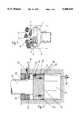
- FIG. 1shows a rotatable tool 1 at the head of which there are several drill bits of different types.
- all the bitsare cutting discs 4 which, on cutting soil or rock, move into slow rotation around their shaft while tool 1 is rotated and fed forward.
- the drill bit rods 5are at the same time rods of pistons 6 of hydraulic cylinders 7, at the heads of which supporting parts 2,3 for the cutting discs 4 are fixed.
- FIG. 2shows a hydraulic system by means of which the backing of a bit is functioning. From the former cylinder, hydraulic pressure enters into cylinder 7 through back-valve 18. The drill bit and the piston are then in a slightly backed, or rearward position.
- the pistonis affected by pressure, e.g. adjusted to 100 bar, over valve 18, pushing the piston to its extreme, or forward position. From the other side of the piston, oil escapes through valve 15, the opening pressure of which is, for instance, 120 bar. Due to the considerably smaller cross-sectional area of the piston, pressure can rise even more thereby opening valve 15 and allowing oil to flow to lower pressure. When no oil leaks out through the oil outlet pipe 12, this is a sign that the piston is in a backed position at least in one of the cylinders.
- valve 19opens letting oil through the piston. Proper opening pressure would be 180 bar for instance. Then also valve 11 must let some oil forward and its opening pressure could be 140 bar. Backing stops as soon as the forward feeding of tool is switched off.
- a situation where a cylinder has moved into backing positioncan be detected from the total or almost total interruption of oil flow from channel 12.
- FIG. 3shows a hydraulic diagram of a series connection of cylinders 24.
- the feeding pressure upper limitis kept at least in 100 bar with regulation valve 22.
- the valvelets oil into tank 21 when the pressure limit is clearly exceeded.
- Valve 23regulates and sustains pressure in cylinders.
- the valve opening pressurecan be 100 bar. If valve 23 allows oil through the same flow as the pump displacement, all drill bits are then in their extreme position. A smaller flow of oil indicates that one or more drill bits are backed.
- FIG. 4shows cylinders 25 connected in parallel.
- a pressure of ab. 100 baris conducted along line 29 to the rear of each cylinder.
- sensor valves 28connected to each cylinder, the same oil is circulated back to the pump. With the pistons in their extreme position, said valves 28 are opened by levers 27, and the oil circulates. Stopping of oil circulation indicates that a bit or the bits are backed. Oil returns over the back valve 33 to the regulation valve 34, which sustains a pressure of ab. 100 bar.
- Regulation valve 31directs oil to the return line if a cylinder is backed and has closed respective valve 28.
- the opening pressure of valve 31can be for instance 140 bar.
- Valve 32is adjustable, and with this valve it is possible to regulate certain counter pressure on the other side of the pistons in situations where pistons are driven outward by pressure.
Landscapes
- Engineering & Computer Science (AREA)
- Life Sciences & Earth Sciences (AREA)
- Geology (AREA)
- Mining & Mineral Resources (AREA)
- Physics & Mathematics (AREA)
- Environmental & Geological Engineering (AREA)
- Fluid Mechanics (AREA)
- General Life Sciences & Earth Sciences (AREA)
- Geochemistry & Mineralogy (AREA)
- Mechanical Engineering (AREA)
- Earth Drilling (AREA)
Abstract
Description
The invention relates to an apparatus for drilling in soil or rock and a method for regulating its penetration, where the penetration is restricted if one or more drill bits are overloaded.
Previously known drilling equipment is described in Finnish Application No. 891706, in which drilling is carried out either by means of a hammering or a rotating tool. The application describes how a hammer furnished with a drill bit and with or without a bit-rotating tool can be backed into its cylinders if the drilling unit is driven too far forward.
The pressure shocks caused by the tool upon drilling are a disadvantage of the above solution, because they disturb the control of backing the whole tool unit. Generally, it is possible to control the backing of the tool only when the drill head is driven on the wall which is being drilled and detection of the whole drill head reading the target is possible as a result of the backing of the tool.
The present invention enables elimination of possible damage to the single bits and dependable control of the backing of the drill bits. The invention is characterized by the features described in the patent claims.
It can be considered the major advantage of the invention that even in a multi-bit tool the single bits can be controlled individually, their overload detected and, accordingly, the feed motion stopped or feeding force restricted in order to prevent the bits from being damaged. With such a tool it is possible to drill in soft soil very fast and on facing rock, no matter at which angle, even at the reach of one bit only, because, due to its backing capacity, the bit is not damaged. A single bit in a conventional multi-bit tool would not remain undamaged in such a situation since it would then have to sustain the whole feeding force alone.
In the following, the invention is described in detail with reference to the enclosed drawings where:
FIG. 1 is a multi-bit drilling tool;
FIG. 2 is a cross-section of a shock-absorbing cylinder of a bit;
FIG. 3 is a diagram of a hydraulic system; and
FIG. 4 is a diagram of an alternative hydraulic system.
FIG. 1 shows arotatable tool 1 at the head of which there are several drill bits of different types. As a matter of principle, all the bits are cuttingdiscs 4 which, on cutting soil or rock, move into slow rotation around their shaft whiletool 1 is rotated and fed forward. Thedrill bit rods 5 are at the same time rods ofpistons 6 of hydraulic cylinders 7, at the heads of which supportingparts cutting discs 4 are fixed.
FIG. 2 shows a hydraulic system by means of which the backing of a bit is functioning. From the former cylinder, hydraulic pressure enters into cylinder 7 through back-valve 18. The drill bit and the piston are then in a slightly backed, or rearward position.
1. If feeding is stopped because of overload in this drill bit, the piston is affected by pressure, e.g. adjusted to 100 bar, overvalve 18, pushing the piston to its extreme, or forward position. From the other side of the piston, oil escapes throughvalve 15, the opening pressure of which is, for instance, 120 bar. Due to the considerably smaller cross-sectional area of the piston, pressure can rise even more thereby openingvalve 15 and allowing oil to flow to lower pressure. When no oil leaks out through theoil outlet pipe 12, this is a sign that the piston is in a backed position at least in one of the cylinders.
When the piston reaches its extreme position thespindles channel 17 and further alongchannel 12 to the next cylinder. The piston remains in its extreme position if there is no overload, though the same pressure of ab. 100 bar prevails on both sides of the piston. In the piston, a force remains active which is caused by the cross-sectional ratio and considered proper load for the drill bit. If there was a similar backed situation in other series-connected cylinders, the pressure of ab. 100 bar alongchannel 12 to the next cylinder would cause travel of the corresponding piston to its extreme position and only then a forward flow of oil alongchannel 12 again.
2. If there is an overload situation in FIG. 2 wherepiston 6 is still backing, valve 19 opens letting oil through the piston. Proper opening pressure would be 180 bar for instance. Then alsovalve 11 must let some oil forward and its opening pressure could be 140 bar. Backing stops as soon as the forward feeding of tool is switched off.
A situation where a cylinder has moved into backing position can be detected from the total or almost total interruption of oil flow fromchannel 12.
FIG. 3 shows a hydraulic diagram of a series connection ofcylinders 24. The feeding pressure upper limit is kept at least in 100 bar withregulation valve 22. The valve lets oil intotank 21 when the pressure limit is clearly exceeded. Valve 23 regulates and sustains pressure in cylinders. The valve opening pressure can be 100 bar. Ifvalve 23 allows oil through the same flow as the pump displacement, all drill bits are then in their extreme position. A smaller flow of oil indicates that one or more drill bits are backed.
FIG. 4 showscylinders 25 connected in parallel. A pressure of ab. 100 bar is conducted alongline 29 to the rear of each cylinder. Throughsensor valves 28 connected to each cylinder, the same oil is circulated back to the pump. With the pistons in their extreme position, saidvalves 28 are opened bylevers 27, and the oil circulates. Stopping of oil circulation indicates that a bit or the bits are backed. Oil returns over the back valve 33 to theregulation valve 34, which sustains a pressure of ab. 100 bar.Regulation valve 31 directs oil to the return line if a cylinder is backed and has closedrespective valve 28. The opening pressure ofvalve 31 can be for instance 140 bar. Valve 32 is adjustable, and with this valve it is possible to regulate certain counter pressure on the other side of the pistons in situations where pistons are driven outward by pressure.
By means of the systems, overload of even one single bit can be detected as an interruption of back-flow oil. Then the feeding of the tool may be switched-off or the feeding force reduced so much that even a single bit sustains the force without damage if only one of the bits hits on a hard surface such as rock. After this, driving is continued with a small pushing force till the bit has managed the rock and moved off the backed position or till the oncoming rock has broadened out in front of several bits. Then the backed single bit is no longer loaded by a very great pushing force and has the possibility of reaching its extreme position. Hereafter it can be tested whether a greater pushing force could be used. The invention is not limited only to the described embodiments but it can be modified within the limits of the inventive ideas introduced in the patent claims. The flexibility of drill bits can be provided even mechanically in using, for instance, springs or combinations of mechanical and medium operated devices.
Claims (7)
1. Apparatus for drilling soil or rock comprising a rotatable tool having a drill head, said rotatable tool being moveable in a direction towards said drill head along its axis of rotation to effect drilling;
a plurality of drill bits mounted on said drill head, each of said drill bits being mounted on a respective member secured to said rotatable tool for movement therewith, each of said members being individually moveable between a forward position towards the forward end of said drill head and a rearward position;
means for maintaining said member in said forward position when, in use, the drill bits are under proper load;
means for permitting any one of said members to move rearwardly to said rearward position when, in use, the drill bit is overloaded; and
means for determining that, in use, any one of said members has moved rearwardly away from said forward position as a result of overload to enable a driving force applied to said tool to be restricted.
2. Apparatus according to claim 1 wherein said members comprise pistons, said pistons being mounted in cylinders which are fixedly secured to said rotatable tool, and wherein said determining means comprises hydraulic means for determining that, in use, any one of said pistons has moved rearwardly away from said forward position.
3. Apparatus according to claim 2 wherein said piston position maintaining means comprises hydraulic means for applying a hydraulic force to any one of said pistons.
4. Apparatus according to claim 3 further comprising means for adjusting said hydraulic force.
5. A method for regulating the penetration of a drilling apparatus in rock or soil, said method comprising the steps of:
a) providing an apparatus for drilling rock or soil, said apparatus comprising:
a rotatable tool having a drill head, said rotatable tool being moveable in a direction towards said drill head along its axis of rotation to effect drilling;
a plurality of drill bits mounted on said drill head, each of said drill bits being mounted on a respective member secured to said rotatable tool for movement therewith, each of said members being individually moveable between a forward position towards the forward end of said drill head and a rearward position;
means for maintaining said member in said forward position when, in use, the drill bits are under proper load;
means for permitting any one of said members to move rearwardly to said rearward position when, in use, the respective drill bit is overloaded; and
means for determining that, in use, any one of said members has moved rearwardly away from said forward position as a result of overload to enable a driving force applied to said tool to be restricted;
b) applying a drilling force to said rotatable tool to effect drilling of rock or soil with the drill bit under proper load; and
c) upon determining that one or more of said members has moved rearwardly away from said forward position, restricting said drilling force.
6. A method according to claim 5 further comprising the steps of:
d) after restricting said drilling force, continuing drilling until said one or more members return to their forward position; and
e) increasing said drilling force to again place the drill bits under proper load.
7. A method according to claim 5 wherein, in step c), the drilling force is restricted, at most, to an amount such that a single drill bit, in use, is under proper load.
Applications Claiming Priority (3)
| Application Number | Priority Date | Filing Date | Title |
|---|---|---|---|
| FI911415 | 1991-03-25 | ||
| FI911415AFI91552C (en) | 1991-03-25 | 1991-03-25 | Drilling rig and method of adjusting its progress |
| PCT/FI1992/000085WO1992016718A1 (en) | 1991-03-25 | 1992-03-25 | A drilling equipment and a method for regulating its penetration |
Publications (1)
| Publication Number | Publication Date |
|---|---|
| US5388649Atrue US5388649A (en) | 1995-02-14 |
Family
ID=8532175
Family Applications (1)
| Application Number | Title | Priority Date | Filing Date |
|---|---|---|---|
| US08/119,234Expired - Fee RelatedUS5388649A (en) | 1991-03-25 | 1992-03-25 | Drilling equipment and a method for regulating its penetration |
Country Status (8)
| Country | Link |
|---|---|
| US (1) | US5388649A (en) |
| EP (1) | EP0577664B1 (en) |
| JP (1) | JPH06506031A (en) |
| AU (1) | AU1431692A (en) |
| CA (1) | CA2107099A1 (en) |
| DE (1) | DE69223614T2 (en) |
| FI (1) | FI91552C (en) |
| WO (1) | WO1992016718A1 (en) |
Cited By (34)
| Publication number | Priority date | Publication date | Assignee | Title |
|---|---|---|---|---|
| US5564455A (en)* | 1995-01-06 | 1996-10-15 | The Charles Machine Works, Inc. | Hydraulic circuit for automatic control of a horizontal boring machine |
| US6142250A (en)* | 1997-04-26 | 2000-11-07 | Camco International (Uk) Limited | Rotary drill bit having moveable formation-engaging members |
| US6186248B1 (en) | 1995-12-12 | 2001-02-13 | Boart Longyear Company | Closed loop control system for diamond core drilling |
| US6298930B1 (en)* | 1999-08-26 | 2001-10-09 | Baker Hughes Incorporated | Drill bits with controlled cutter loading and depth of cut |
| US6460631B2 (en) | 1999-08-26 | 2002-10-08 | Baker Hughes Incorporated | Drill bits with reduced exposure of cutters |
| US6659199B2 (en) | 2001-08-13 | 2003-12-09 | Baker Hughes Incorporated | Bearing elements for drill bits, drill bits so equipped, and method of drilling |
| US20060048973A1 (en)* | 2004-09-09 | 2006-03-09 | Brackin Van J | Rotary drill bits including at least one substantially helically extending feature, methods of operation and design thereof |
| US20060054362A1 (en)* | 2002-11-18 | 2006-03-16 | Teijo Hulkkonen | Bit assembly for a hammering drill |
| US7198119B1 (en)* | 2005-11-21 | 2007-04-03 | Hall David R | Hydraulic drill bit assembly |
| US20070151770A1 (en)* | 2005-12-14 | 2007-07-05 | Thomas Ganz | Drill bits with bearing elements for reducing exposure of cutters |
| US20070221408A1 (en)* | 2005-11-21 | 2007-09-27 | Hall David R | Drilling at a Resonant Frequency |
| US20070229232A1 (en)* | 2006-03-23 | 2007-10-04 | Hall David R | Drill Bit Transducer Device |
| US20080099243A1 (en)* | 2006-10-27 | 2008-05-01 | Hall David R | Method of Assembling a Drill Bit with a Jack Element |
| US20090133936A1 (en)* | 2006-03-23 | 2009-05-28 | Hall David R | Lead the Bit Rotary Steerable Tool |
| US20090236148A1 (en)* | 2005-11-21 | 2009-09-24 | Hall David R | Flow Guide Actuation |
| US20100000794A1 (en)* | 2005-11-21 | 2010-01-07 | Hall David R | Lead the Bit Rotary Steerable Tool |
| US20100044109A1 (en)* | 2007-09-06 | 2010-02-25 | Hall David R | Sensor for Determining a Position of a Jack Element |
| US20100065334A1 (en)* | 2005-11-21 | 2010-03-18 | Hall David R | Turbine Driven Hammer that Oscillates at a Constant Frequency |
| US20100108385A1 (en)* | 2007-09-06 | 2010-05-06 | Hall David R | Downhole Jack Assembly Sensor |
| US20100263937A1 (en)* | 2009-04-15 | 2010-10-21 | Overstreet James L | Methods of forming and repairing cutting element pockets in earth-boring tools with depth-of-cut control features, and tools and structures formed by such methods |
| US20100276200A1 (en)* | 2009-04-30 | 2010-11-04 | Baker Hughes Incorporated | Bearing blocks for drill bits, drill bit assemblies including bearing blocks and related methods |
| US7866416B2 (en) | 2007-06-04 | 2011-01-11 | Schlumberger Technology Corporation | Clutch for a jack element |
| US20110079438A1 (en)* | 2009-10-05 | 2011-04-07 | Baker Hughes Incorporated | Drill bits and tools for subterranean drilling, methods of manufacturing such drill bits and tools and methods of directional and off center drilling |
| US20110100721A1 (en)* | 2007-06-14 | 2011-05-05 | Baker Hughes Incorporated | Rotary drill bits including bearing blocks |
| US8011457B2 (en) | 2006-03-23 | 2011-09-06 | Schlumberger Technology Corporation | Downhole hammer assembly |
| US8020471B2 (en) | 2005-11-21 | 2011-09-20 | Schlumberger Technology Corporation | Method for manufacturing a drill bit |
| US8225883B2 (en) | 2005-11-21 | 2012-07-24 | Schlumberger Technology Corporation | Downhole percussive tool with alternating pressure differentials |
| US8281882B2 (en) | 2005-11-21 | 2012-10-09 | Schlumberger Technology Corporation | Jack element for a drill bit |
| US8297375B2 (en) | 2005-11-21 | 2012-10-30 | Schlumberger Technology Corporation | Downhole turbine |
| US8528664B2 (en) | 2005-11-21 | 2013-09-10 | Schlumberger Technology Corporation | Downhole mechanism |
| US8701799B2 (en) | 2009-04-29 | 2014-04-22 | Schlumberger Technology Corporation | Drill bit cutter pocket restitution |
| US20140262511A1 (en)* | 2013-03-12 | 2014-09-18 | Baker Hughes Incorporated | Drill Bit with Extension Elements in Hydraulic Communications to Adjust Loads Thereon |
| US8950517B2 (en) | 2005-11-21 | 2015-02-10 | Schlumberger Technology Corporation | Drill bit with a retained jack element |
| US11795763B2 (en) | 2020-06-11 | 2023-10-24 | Schlumberger Technology Corporation | Downhole tools having radially extendable elements |
Citations (7)
| Publication number | Priority date | Publication date | Assignee | Title |
|---|---|---|---|---|
| DE158410C (en)* | ||||
| US1612338A (en)* | 1923-10-03 | 1926-12-28 | Joseph R Wilson | Drilling mechanism |
| US2819041A (en)* | 1953-02-24 | 1958-01-07 | William J Beckham | Percussion type rock bit |
| US2942850A (en)* | 1957-07-23 | 1960-06-28 | Mckee Company | Multiple drill |
| SU434168A1 (en)* | 1973-01-25 | 1974-06-30 | Э. И. Завь лов, П. М. Степанов , А. П. Моторненко | MECHANICAL BREEDING DESTROYING BODY |
| US3924690A (en)* | 1973-01-09 | 1975-12-09 | Halifax Tool Co Ltd | Percussion drill control means |
| US4386669A (en)* | 1980-12-08 | 1983-06-07 | Evans Robert F | Drill bit with yielding support and force applying structure for abrasion cutting elements |
- 1991
- 1991-03-25FIFI911415Apatent/FI91552C/ennot_activeIP Right Cessation
- 1992
- 1992-03-25USUS08/119,234patent/US5388649A/ennot_activeExpired - Fee Related
- 1992-03-25EPEP92907201Apatent/EP0577664B1/ennot_activeExpired - Lifetime
- 1992-03-25CACA002107099Apatent/CA2107099A1/ennot_activeAbandoned
- 1992-03-25AUAU14316/92Apatent/AU1431692A/ennot_activeAbandoned
- 1992-03-25JPJP4506879Apatent/JPH06506031A/enactivePending
- 1992-03-25WOPCT/FI1992/000085patent/WO1992016718A1/enactiveIP Right Grant
- 1992-03-25DEDE69223614Tpatent/DE69223614T2/ennot_activeExpired - Fee Related
Patent Citations (7)
| Publication number | Priority date | Publication date | Assignee | Title |
|---|---|---|---|---|
| DE158410C (en)* | ||||
| US1612338A (en)* | 1923-10-03 | 1926-12-28 | Joseph R Wilson | Drilling mechanism |
| US2819041A (en)* | 1953-02-24 | 1958-01-07 | William J Beckham | Percussion type rock bit |
| US2942850A (en)* | 1957-07-23 | 1960-06-28 | Mckee Company | Multiple drill |
| US3924690A (en)* | 1973-01-09 | 1975-12-09 | Halifax Tool Co Ltd | Percussion drill control means |
| SU434168A1 (en)* | 1973-01-25 | 1974-06-30 | Э. И. Завь лов, П. М. Степанов , А. П. Моторненко | MECHANICAL BREEDING DESTROYING BODY |
| US4386669A (en)* | 1980-12-08 | 1983-06-07 | Evans Robert F | Drill bit with yielding support and force applying structure for abrasion cutting elements |
Non-Patent Citations (2)
| Title |
|---|
| Derwent s Abstract, No. 84 80 378/13; 16.06.81.* |
| Derwent's Abstract, No. 84-80 378/13; 16.06.81. |
Cited By (76)
| Publication number | Priority date | Publication date | Assignee | Title |
|---|---|---|---|---|
| USRE37923E1 (en) | 1995-01-06 | 2002-12-10 | The Charles Machine Works, Inc. | Hydraulic circuit for automatic control of a horizontal boring machine |
| US5564455A (en)* | 1995-01-06 | 1996-10-15 | The Charles Machine Works, Inc. | Hydraulic circuit for automatic control of a horizontal boring machine |
| US6186248B1 (en) | 1995-12-12 | 2001-02-13 | Boart Longyear Company | Closed loop control system for diamond core drilling |
| US6142250A (en)* | 1997-04-26 | 2000-11-07 | Camco International (Uk) Limited | Rotary drill bit having moveable formation-engaging members |
| US20050284660A1 (en)* | 1999-08-26 | 2005-12-29 | Dykstra Mark W | Drill bits with reduced exposure of cutters |
| US7096978B2 (en) | 1999-08-26 | 2006-08-29 | Baker Hughes Incorporated | Drill bits with reduced exposure of cutters |
| US7814990B2 (en) | 1999-08-26 | 2010-10-19 | Baker Hughes Incorporated | Drilling apparatus with reduced exposure of cutters and methods of drilling |
| US6779613B2 (en) | 1999-08-26 | 2004-08-24 | Baker Hughes Incorporated | Drill bits with controlled exposure of cutters |
| US20040216926A1 (en)* | 1999-08-26 | 2004-11-04 | Dykstra Mark W. | Drill bits with reduced exposure of cutters |
| US6935441B2 (en) | 1999-08-26 | 2005-08-30 | Baker Hughes Incorporated | Drill bits with reduced exposure of cutters |
| US20110114392A1 (en)* | 1999-08-26 | 2011-05-19 | Baker Hughes Incorporated | Drilling apparatus with reduced exposure of cutters and methods of drilling |
| US6298930B1 (en)* | 1999-08-26 | 2001-10-09 | Baker Hughes Incorporated | Drill bits with controlled cutter loading and depth of cut |
| US8066084B2 (en) | 1999-08-26 | 2011-11-29 | Baker Hughes Incorporated | Drilling apparatus with reduced exposure of cutters and methods of drilling |
| US6460631B2 (en) | 1999-08-26 | 2002-10-08 | Baker Hughes Incorporated | Drill bits with reduced exposure of cutters |
| US8172008B2 (en) | 1999-08-26 | 2012-05-08 | Baker Hughes Incorporated | Drilling apparatus with reduced exposure of cutters and methods of drilling |
| US20060278436A1 (en)* | 1999-08-26 | 2006-12-14 | Dykstra Mark W | Drilling apparatus with reduced exposure of cutters |
| US6659199B2 (en) | 2001-08-13 | 2003-12-09 | Baker Hughes Incorporated | Bearing elements for drill bits, drill bits so equipped, and method of drilling |
| US7124843B2 (en)* | 2002-11-18 | 2006-10-24 | Teijo Hulkkonen | Bit assembly for a hammering drill |
| US20060054362A1 (en)* | 2002-11-18 | 2006-03-16 | Teijo Hulkkonen | Bit assembly for a hammering drill |
| US8011275B2 (en) | 2004-09-09 | 2011-09-06 | Baker Hughes Incorporated | Methods of designing rotary drill bits including at least one substantially helically extending feature |
| US20060048973A1 (en)* | 2004-09-09 | 2006-03-09 | Brackin Van J | Rotary drill bits including at least one substantially helically extending feature, methods of operation and design thereof |
| US20080142271A1 (en)* | 2004-09-09 | 2008-06-19 | Baker Hughes Incorporated | Methods of designing rotary drill bits including at least one substantially helically extending feature |
| US7360608B2 (en) | 2004-09-09 | 2008-04-22 | Baker Hughes Incorporated | Rotary drill bits including at least one substantially helically extending feature and methods of operation |
| US8950517B2 (en) | 2005-11-21 | 2015-02-10 | Schlumberger Technology Corporation | Drill bit with a retained jack element |
| US7328755B2 (en)* | 2005-11-21 | 2008-02-12 | Hall David R | Hydraulic drill bit assembly |
| US8281882B2 (en) | 2005-11-21 | 2012-10-09 | Schlumberger Technology Corporation | Jack element for a drill bit |
| US7591327B2 (en)* | 2005-11-21 | 2009-09-22 | Hall David R | Drilling at a resonant frequency |
| US20090236148A1 (en)* | 2005-11-21 | 2009-09-24 | Hall David R | Flow Guide Actuation |
| US20100000794A1 (en)* | 2005-11-21 | 2010-01-07 | Hall David R | Lead the Bit Rotary Steerable Tool |
| US8267196B2 (en) | 2005-11-21 | 2012-09-18 | Schlumberger Technology Corporation | Flow guide actuation |
| US20100065334A1 (en)* | 2005-11-21 | 2010-03-18 | Hall David R | Turbine Driven Hammer that Oscillates at a Constant Frequency |
| US8528664B2 (en) | 2005-11-21 | 2013-09-10 | Schlumberger Technology Corporation | Downhole mechanism |
| US8297375B2 (en) | 2005-11-21 | 2012-10-30 | Schlumberger Technology Corporation | Downhole turbine |
| US8522897B2 (en) | 2005-11-21 | 2013-09-03 | Schlumberger Technology Corporation | Lead the bit rotary steerable tool |
| US8225883B2 (en) | 2005-11-21 | 2012-07-24 | Schlumberger Technology Corporation | Downhole percussive tool with alternating pressure differentials |
| US8408336B2 (en) | 2005-11-21 | 2013-04-02 | Schlumberger Technology Corporation | Flow guide actuation |
| US7198119B1 (en)* | 2005-11-21 | 2007-04-03 | Hall David R | Hydraulic drill bit assembly |
| US20070114064A1 (en)* | 2005-11-21 | 2007-05-24 | Hall David R | Hydraulic Drill Bit Assembly |
| US8020471B2 (en) | 2005-11-21 | 2011-09-20 | Schlumberger Technology Corporation | Method for manufacturing a drill bit |
| US20070221408A1 (en)* | 2005-11-21 | 2007-09-27 | Hall David R | Drilling at a Resonant Frequency |
| US8297378B2 (en) | 2005-11-21 | 2012-10-30 | Schlumberger Technology Corporation | Turbine driven hammer that oscillates at a constant frequency |
| US20070151770A1 (en)* | 2005-12-14 | 2007-07-05 | Thomas Ganz | Drill bits with bearing elements for reducing exposure of cutters |
| US8141665B2 (en) | 2005-12-14 | 2012-03-27 | Baker Hughes Incorporated | Drill bits with bearing elements for reducing exposure of cutters |
| US8448726B2 (en) | 2005-12-14 | 2013-05-28 | Baker Hughes Incorporated | Drill bits with bearing elements for reducing exposure of cutters |
| US8752654B2 (en) | 2005-12-14 | 2014-06-17 | Baker Hughes Incorporated | Drill bits with bearing elements for reducing exposure of cutters |
| US8011457B2 (en) | 2006-03-23 | 2011-09-06 | Schlumberger Technology Corporation | Downhole hammer assembly |
| US20070229232A1 (en)* | 2006-03-23 | 2007-10-04 | Hall David R | Drill Bit Transducer Device |
| US8316964B2 (en) | 2006-03-23 | 2012-11-27 | Schlumberger Technology Corporation | Drill bit transducer device |
| US8360174B2 (en) | 2006-03-23 | 2013-01-29 | Schlumberger Technology Corporation | Lead the bit rotary steerable tool |
| US20090133936A1 (en)* | 2006-03-23 | 2009-05-28 | Hall David R | Lead the Bit Rotary Steerable Tool |
| US7954401B2 (en) | 2006-10-27 | 2011-06-07 | Schlumberger Technology Corporation | Method of assembling a drill bit with a jack element |
| US20080099243A1 (en)* | 2006-10-27 | 2008-05-01 | Hall David R | Method of Assembling a Drill Bit with a Jack Element |
| US7866416B2 (en) | 2007-06-04 | 2011-01-11 | Schlumberger Technology Corporation | Clutch for a jack element |
| US8307919B2 (en) | 2007-06-04 | 2012-11-13 | Schlumberger Technology Corporation | Clutch for a jack element |
| US8757297B2 (en) | 2007-06-14 | 2014-06-24 | Baker Hughes Incorporated | Rotary drill bits including bearing blocks |
| US20110100721A1 (en)* | 2007-06-14 | 2011-05-05 | Baker Hughes Incorporated | Rotary drill bits including bearing blocks |
| US8459382B2 (en) | 2007-06-14 | 2013-06-11 | Baker Hughes Incorporated | Rotary drill bits including bearing blocks |
| US20100044109A1 (en)* | 2007-09-06 | 2010-02-25 | Hall David R | Sensor for Determining a Position of a Jack Element |
| US8499857B2 (en) | 2007-09-06 | 2013-08-06 | Schlumberger Technology Corporation | Downhole jack assembly sensor |
| US7967083B2 (en) | 2007-09-06 | 2011-06-28 | Schlumberger Technology Corporation | Sensor for determining a position of a jack element |
| US20100108385A1 (en)* | 2007-09-06 | 2010-05-06 | Hall David R | Downhole Jack Assembly Sensor |
| US8943663B2 (en) | 2009-04-15 | 2015-02-03 | Baker Hughes Incorporated | Methods of forming and repairing cutting element pockets in earth-boring tools with depth-of-cut control features, and tools and structures formed by such methods |
| US9291002B2 (en) | 2009-04-15 | 2016-03-22 | Baker Hughes Incorporated | Methods of repairing cutting element pockets in earth-boring tools with depth-of-cut control features |
| US20100263937A1 (en)* | 2009-04-15 | 2010-10-21 | Overstreet James L | Methods of forming and repairing cutting element pockets in earth-boring tools with depth-of-cut control features, and tools and structures formed by such methods |
| US10221628B2 (en) | 2009-04-15 | 2019-03-05 | Baker Hughes Incorporated | Methods of repairing cutting element pockets in earth-boring tools with depth-of-cut control features |
| US8701799B2 (en) | 2009-04-29 | 2014-04-22 | Schlumberger Technology Corporation | Drill bit cutter pocket restitution |
| US20100276200A1 (en)* | 2009-04-30 | 2010-11-04 | Baker Hughes Incorporated | Bearing blocks for drill bits, drill bit assemblies including bearing blocks and related methods |
| US9890597B2 (en) | 2009-10-05 | 2018-02-13 | Baker Hughes Incorporated | Drill bits and tools for subterranean drilling including rubbing zones and related methods |
| US9309723B2 (en) | 2009-10-05 | 2016-04-12 | Baker Hughes Incorporated | Drill bits and tools for subterranean drilling, methods of manufacturing such drill bits and tools and methods of directional and off center drilling |
| US20110079438A1 (en)* | 2009-10-05 | 2011-04-07 | Baker Hughes Incorporated | Drill bits and tools for subterranean drilling, methods of manufacturing such drill bits and tools and methods of directional and off center drilling |
| US9267329B2 (en)* | 2013-03-12 | 2016-02-23 | Baker Hughes Incorporated | Drill bit with extension elements in hydraulic communications to adjust loads thereon |
| CN105189907A (en)* | 2013-03-12 | 2015-12-23 | 贝克休斯公司 | Drill bit with extension elements in hydraulic communications to adjust loads thereon |
| US20140262511A1 (en)* | 2013-03-12 | 2014-09-18 | Baker Hughes Incorporated | Drill Bit with Extension Elements in Hydraulic Communications to Adjust Loads Thereon |
| RU2690240C2 (en)* | 2013-03-12 | 2019-05-31 | Бейкер Хьюз Инкорпорейтед | Drilling bit with sliding elements with hydraulic link to control load acting on them |
| US11795763B2 (en) | 2020-06-11 | 2023-10-24 | Schlumberger Technology Corporation | Downhole tools having radially extendable elements |
| US12435575B2 (en) | 2020-06-11 | 2025-10-07 | Schlumberger Technology Corporation | Downhole tools having radially extendable elements |
Also Published As
| Publication number | Publication date |
|---|---|
| EP0577664A1 (en) | 1994-01-12 |
| JPH06506031A (en) | 1994-07-07 |
| FI911415A0 (en) | 1991-03-25 |
| EP0577664B1 (en) | 1997-12-17 |
| DE69223614T2 (en) | 1998-07-30 |
| CA2107099A1 (en) | 1992-09-26 |
| DE69223614D1 (en) | 1998-01-29 |
| FI91552B (en) | 1994-03-31 |
| FI911415L (en) | 1992-09-26 |
| AU1431692A (en) | 1992-10-21 |
| WO1992016718A1 (en) | 1992-10-01 |
| FI91552C (en) | 1994-07-11 |
Similar Documents
| Publication | Publication Date | Title |
|---|---|---|
| US5388649A (en) | Drilling equipment and a method for regulating its penetration | |
| US4006783A (en) | Hydraulic operated rock drilling apparatus | |
| CA1084900A (en) | Controls for hydraulic percussion drill | |
| EP1064123B1 (en) | Method and apparatus for controlling drilling of rock drill | |
| US5117921A (en) | Hydraulically operated hammer drill | |
| US4355691A (en) | Hydraulic drilling apparatus | |
| US10610868B2 (en) | Hydraulic cylinder system for rock crushers | |
| FI86008C (en) | Method and apparatus for controlling a rock drilling machine | |
| US5913371A (en) | Apparatus for controlling the feed drive of a boring mechanism for making earth bores | |
| EP1558836A1 (en) | Arrangement for controlling rock drilling | |
| DE69024222T2 (en) | CONTROL METHOD FOR DRILLING DEVICES | |
| US20030155140A1 (en) | Method of opening joints between drilling components, and rock drill | |
| JP5830223B2 (en) | Rock drill and method related to the rock drill | |
| DE3336540A1 (en) | IMPACT DRILLING MACHINE | |
| AU2005286447B2 (en) | Arrangement for controlling percussive rock drilling | |
| SE441850B (en) | Tunneling machine | |
| FI85178B (en) | FOERFARANDE I ROTATIONSBORRNING OCH ROTATIONSBORRNINGSANORDNING. | |
| US6119793A (en) | Rock drill | |
| FI81886C (en) | ANORDINATION FOR SLAGBORRNING. | |
| FI90277B (en) | drilling | |
| FI56722C (en) | HYDRAULISK BORRMASKIN SPECIELLT BERGBORRMASKIN | |
| CA2893559C (en) | Hydraulic cylinder system for rock crushers | |
| AT407071B (en) | DEVICE FOR DAMPING VIBRATIONS OF PARTIAL CUTTING MACHINES | |
| KR100661394B1 (en) | Overload protection system of mixing mill for tire manufacturing | |
| DE1427104C (en) | Vice for machine tool tables |
Legal Events
| Date | Code | Title | Description |
|---|---|---|---|
| FEPP | Fee payment procedure | Free format text:PAYOR NUMBER ASSIGNED (ORIGINAL EVENT CODE: ASPN); ENTITY STATUS OF PATENT OWNER: SMALL ENTITY | |
| REMI | Maintenance fee reminder mailed | ||
| LAPS | Lapse for failure to pay maintenance fees | ||
| FP | Lapsed due to failure to pay maintenance fee | Effective date:19990214 | |
| STCH | Information on status: patent discontinuation | Free format text:PATENT EXPIRED DUE TO NONPAYMENT OF MAINTENANCE FEES UNDER 37 CFR 1.362 |