US5388099A - Backplane wiring for hub in packet data communications system - Google Patents
Backplane wiring for hub in packet data communications systemDownload PDFInfo
- Publication number
- US5388099A US5388099AUS07/964,791US96479192AUS5388099AUS 5388099 AUS5388099 AUS 5388099AUS 96479192 AUS96479192 AUS 96479192AUS 5388099 AUS5388099 AUS 5388099A
- Authority
- US
- United States
- Prior art keywords
- line cards
- ports
- transmit
- line
- port
- Prior art date
- Legal status (The legal status is an assumption and is not a legal conclusion. Google has not performed a legal analysis and makes no representation as to the accuracy of the status listed.)
- Expired - Lifetime
Links
- 238000004891communicationMethods0.000titleclaimsabstractdescription17
- 238000000034methodMethods0.000claimsdescription16
- 239000011159matrix materialSubstances0.000claims2
- 230000008878couplingEffects0.000abstractdescription2
- 238000010168coupling processMethods0.000abstractdescription2
- 238000005859coupling reactionMethods0.000abstractdescription2
- 238000010586diagramMethods0.000description11
- 230000006870functionEffects0.000description7
- 230000008569processEffects0.000description7
- 230000001360synchronised effectEffects0.000description6
- 238000010276constructionMethods0.000description5
- 230000005540biological transmissionEffects0.000description2
- 238000012986modificationMethods0.000description2
- 230000004048modificationEffects0.000description2
- 238000012545processingMethods0.000description2
- 238000012546transferMethods0.000description2
- 241000191291Abies albaSpecies0.000description1
- 230000006399behaviorEffects0.000description1
- 230000002457bidirectional effectEffects0.000description1
- 230000001010compromised effectEffects0.000description1
- 239000000835fiberSubstances0.000description1
- 230000008571general functionEffects0.000description1
- 230000013011matingEffects0.000description1
- 230000004044responseEffects0.000description1
- 230000003068static effectEffects0.000description1
- 238000013519translationMethods0.000description1
Images


Classifications
- H—ELECTRICITY
- H04—ELECTRIC COMMUNICATION TECHNIQUE
- H04L—TRANSMISSION OF DIGITAL INFORMATION, e.g. TELEGRAPHIC COMMUNICATION
- H04L12/00—Data switching networks
- H04L12/28—Data switching networks characterised by path configuration, e.g. LAN [Local Area Networks] or WAN [Wide Area Networks]
- H04L12/44—Star or tree networks
- H—ELECTRICITY
- H05—ELECTRIC TECHNIQUES NOT OTHERWISE PROVIDED FOR
- H05K—PRINTED CIRCUITS; CASINGS OR CONSTRUCTIONAL DETAILS OF ELECTRIC APPARATUS; MANUFACTURE OF ASSEMBLAGES OF ELECTRICAL COMPONENTS
- H05K1/00—Printed circuits
- H05K1/02—Details
- H05K1/14—Structural association of two or more printed circuits
Definitions
- This inventionrelates to a backplane wiring scheme as used in hub in a packet data communications system, and more particularly to a backplane wiring scheme which allows line cards to be connected as either a bus or a ring configuration.
- each line cardis a network segment, a station or a bridge to other stations or segments
- the connectionis usually in either a ring or a bus topology.
- a bus topologyuses a collection of parallel wires running across the backplane. Each line card connects to the bus and uses one or more of the bus wires to communicate with the other line cards.
- the busis often divided into channels, each channel containing some fixed number of bus wires. The bus wires in a given channel are all used in the same manner, whereas different channels can be used independently.
- a channelcan be used as a broadcast bus, with some specified arbitration scheme, to provide a dynamic communication capability between two or more line cards; or it can be used in a fixed manner with the channel forming a dedicated communication link between two or more cards, the broadcast bus scheme is typically used to support connections amongst Ethernet repeaters in smart hubs; the fixed channel scheme is often used to support ring topologies as found in FDDI wiring concentrators. Bus topologies often require the use of bus-terminating resistors placed at each end of the bus to improve the electrical performance. Without these resistors, communication bandwidth is compromised.
- the ring topologyis used exclusively to support interconnection amongst line cards that are wired together in a closed one-way ring.
- the backplaneconnects the output of one line card to the input of the next line card.
- the disadvantage of this topologyis (as with Christmas tree lights) if one line card dies or is removed, the whole ring dies. Palliative schemes to overcome this problem have been suggested, but none match the richness of interconnect offered by bus topologies.
- a backplane wiring schemefor use in a hub of a packet data communications system.
- Line cardsare connected to the backplane wiring arrangement in the hub, where each line card is a coupling to a network segment, a station or a to a bridge to other stations or segments.
- the connectionis usually in either a ring or a bus topology, and increased flexibility, reduced power consumption, and easier implementation are provided by a unique wiring scheme.
- Each line cardhas a number of receive ports (e.g., N-1) and has two transmit ports, the transmit ports including a transmit-left port and a transmit-right port.
- the receive ports and transmit portsare arranged in a regular linear pattern on an edge of each of said line cards.
- the line cardsare inserted in backplane slots, and backplane wiring paths are configured diagonally between ports of the cards to connect the transmit-left ports of the line cards to receive ports of line cards to the left and to connect the transmit-right ports of the line cards to receive ports of line cards to the right.
- the line cardsare thereby configured as a bus.
- the transmit-left port and a top one of the receive portsare activated for all of the line cards, and the transmit-right port of only the left-most line card, are activated, the line cards are thereby configured as a ring.
- FIG. 1is a diagram in block form of a communications network which may use features according to one embodiment of the invention
- FIG. 1ais an electrical diagram in block form of a controller for the communications network of FIG. 1;
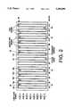
- FIG. 2is a diagram of construction of a hub used in the system of FIG. 1, with slots for line cards and a backplane wiring scheme;
- FIG. 3is a diagram of a form of a backplane wiring parallel bus used in the hub of FIG. 2;
- FIG. 4is a diagram of a way of wiring the backplane of FIG. 2, according to one example of construction
- FIG. 5is a diagram of a backplane wiring scheme according to one embodiment of the invention.
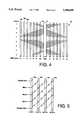
- FIG. 6is a diagram of a wiring arrangement using the scheme of FIG. 5 to create a bus topology
- FIG. 7is a diagram of a wiring arrangement using the scheme of FIG. 5 to create a ring topology
- FIG. 8is a diagram of a crossbar arrangement according to a separate embodiment of construction of the system of FIG. 1;
- FIG. 9is a diagram of a detail of the crosspoints in the embodiment of FIG. 8.
- FIG. 10is a diagram of implementation of a bus topology in the embodiment of FIGS. 8 and 9.
- a packet data communications networkwhich may use the features of the invention includes a controller 10 for interface between an FDDI link 11 and a crossbar switch device 12.
- the crossbar switch device 12has a number of input/output ports 13, and each one of these ports 13 may be connected by another controller 10 to another network segment 11 such as an FDDI link or a token ring or Ethernet bus, for example.
- the crossbar switch 10ordinarily makes a direct point-to-point interconnect between one port 13 and another port 13, so that the crossbar acts as a bridge or router in the network, linking one network segment to another.
- a station on a link 11sends a packet onto its network segment with a destination address which is on another, different segment.
- the controller 10 for this segmentdetects the address as being that of a station on one of the remote segments, and generates local switching information to send to the crossbar 12 so that the appropriate interconnect can be made to send the packet to the proper port 13 and link 11, via another controller 10.
- the crossbar switch devicecan function as a flexible interconnect device to create a ring or bus using the ports 13, as well as functioning as a point-to-point connector as is the usual case for crossbar switches.
- each port 13 of the crossbarhas a data-in path 14 and a separate data-out path 15.
- the interface between the controller 10 and the FDDI link 11is by way of a media access control (MAC) device 16, functioning to convert the serial light transmission on the incoming fiber optic cable 17 to electrical pulses, to recover the clock, convert the serial data on the optic loop to 6-bit parallel symbols, act as an elastic buffer to allow reclocking of data entering the controller 10, etc.
- MACmedia access control
- the interface between the controller 10 and the MAC device 16is by an incoming 8-bit parallel data path 19a (with additional parity and control lines) and an outgoing 8-bit parallel path 19b.
- the controller 10contains a processor or state machine 20 to execute various processes as will be described, and accesses a packet memory 21 via an interface 22, as well as a content addressable memory (CAM) 23 via interface 24.
- the packet memory 21is addressed by a 20-bit address bus, and data is transferred by a 56-bit bidirectional data bus, included in the interface 22; various control lines are also in the interface 22.
- the CAM 23is driven by a 14-bit bus and various control lines in the interface 24.
- the packet memory 21is a RAM which stores a number of queues for incoming and outgoing data packets, as well as translation tables and hash tables as will be described. In addition, the packet memory stores certain data for which addresses are matched in the CAM 23.
- the controller 10also interfaces with a line card processor 25 by bus 26.
- the line card processor 25is used to execute some diagnostic and initialization functions, and does not operate in routine packet transfer.
- the controller 10contains a processor or state machine 20 to execute various processes for packet data transfer as will be described.
- This processor 20is a microprocessor or the like, executing a stored program, as is well known.
- a hub in a communications network including the system of FIG. 1is constructed, in one embodiment, using a housing or cabinet 30 having a number of line cards 10a, 10b, 10c, etc., (up to twelve line cards in one embodiment, each line card having a controller 10 therein) which are plugged into slots 31 for a backplane wiring arrangement 32 as will be described.
- the crossbar switch 12is also constructed on a card 12a plugged into a slot 33 to connect to the backplane wiring.
- a clock card 34is plugged into a slot in the backplane wiring to supply clocks to provide synchronous timing for all of the components of the backplane on the bus.
- Each one of the line cards 10a, 10b, etc.can contain one of the controllers 10 to engage a port 13 of the crossbar, or, alternatively, more than one of the controllers 10 can be located on one line card so that a line card supports more than one of the ports 13.
- a controller 10 of a line cardhas a network segment such as an FDDI link 11 or another crossbar connected to it; if there are more than one port supported, then there is a link 11 for each port.
- the backplane wiring 32is constructed as a synchronous parallel bus which is arbitrated, with the various line cards 10a, 10b, etc., and the crossbar 12, requesting and being granted access to the bus for each cycle.
- the crossbar switch 12can handle only thirty-six ports, total, in one embodiment.
- the slotsusually not all of the slots have line cards in them, and on a line card there is only one (or two) ports.
- the particular one of the seven potential port positions on a card that is useddepends upon the function to be implemented, as will be described.
- the synchronous parallel busmust contain both input path 14 and output path 15 for each port 13, so the synchronous parallel bus interconnecting all of the slots with the crossbar switch 12 contains a number of complete sets of data-in and data-out lines 14 and 15, with each set including six lines for data-in and six lines for data-out, as seen in FIG. 3.
- the backplane wiring 32includes arbitration lines 36 going from each line card processor 25 to the crossbar; the arbitration lines include a request line and a grant line separately for each one of the line cards.
- Address lines 37are used to designate the port to which data is to be sent, along with a code indicating the type of bus cycle.
- the backplane busacts in a pipelined manner. Data is exchanged in each bus clock cycle, while arbitration and addressing for subsequent cycles are going on. That is, an entire data exchange requires several cycles, but these are pipelined so a complete data exchange occurs on average in every bus cycle.
- the cycles for a data exchangeinclude a request cycle, a grant cycle and address cycle occurring simultaneously, a data send/receive cycle with a response (acknowledge), and an error reporting cycle.
- a controller 10If a controller 10 is sending a packet to another controller 10 on the crossbar, it is handled on a cycle-by-cycle basis; the controller requests the bus when a symbol is ready to send, then when the bus is granted sends to the crossbar the address of the destination followed by the data of this symbol.
- a common path(the backplane bus) is thus shared for all connections between ports 13 of the crossbar, on a time-division multiplexed basis.
- a crossbar switch control processor 38 in the crossbar card 33receives all of the lines of the backplane wiring 32 and controls arbitration for the bus as described.
- At least one of the seven potential ports on a line cardis usually connected by the backplane wiring directly to the crossbar switch 12 for point-to-point communication with any of the ports 13 of the crossbar.
- port #3 and port #4 of each of twelve line cardsis connected to the crossbar switch 12 by the backplane bus, and port #0 and port #7 are likewise directly connected to the crossbar for line cards #4, #5, #8, #9, and #10.
- any of the directly-connected ports #'scan have their crossbar connections controlled by the controller 38.
- other port #'s of the line cards for the hubhave differently-wired connections to provide "smart" hub functions.
- an important feature of one embodimentis the provision of separate connecting paths between certain ones of the line cards, these paths not using the backplane wiring 32 of FIG. 3 or going through the crossbar switch 12.
- a four-slot backplaneincludes slots 31 for line cards 10m, 10n, 10p and 10q, referred to as backplane slot-1, slot-2, slot-3, and slot-4.
- Each line card 10p, etc.has five logical connections to the backplane, two indicated by a " ⁇ being transmit ports and three indicated by a " ⁇ " being receive ports. Data flows from the line card into the backplane at the transmit ports, and data flows from backplane onto the line card at the receive ports.
- N-1 receive portsfor a backplane with N slots.
- the wiring pattern shownis diagonal, rather than horizontal, with connections 10s allowing data to flow from a transmit port to a receive port.
- the connections (ports)are either transmit or receive, whereas in a typical bus topology of a backplane, each port is required to support both transmit and receive capability, as is used for the backplane wiring of FIGS. 2 and 3 connecting all of the slots to the crossbar and clock card.
- the wiring scheme of FIG. 5includes the "bus” and "ring” topologies as subsets. If each daughter card 10m, 10n, 10p, and 10q connects the two transmit ports (transmit-left and transmit-right) together internally (indicated by a jumper 10j) as seen in FIG. 6, a bus is provided in which any port (card) can transmit to the bus and all other ports will simultaneously receive.
- the backplane wiring to implement this constructionlooks like a typical bus, except that the bus is "helical” rather than horizontal.
- a ring topologyis provided. The ring is completed by including the transmit-right port of slot-1.
- the three cards in slot-1 to slot-3 of FIG. 7each receive at their receive-1 port data frown the transmit-left port of the card to their right, will the card in slot-4 receives from the transmit-right port of the card in slot-1, completing a closed ring.
- No cardcan transmit to any other card except by the connection of FIG. 7.
- the port-0, port-1, port-2, port-3, port-5, port-6, and port-7 of line cards in slot-0 to slot-3for example, can be connected as in FIGS. 5-7, simulating a bus or a ring in a permanent configuration, not using the crossbar switch 12.
- the scheme of FIGS. 8-10can support multiple rings, where each ring includes an arbitrary collection of line cards (where each line card belongs to only one ring). This flexibility is often required in token ring hubs and FDDI wiring concentrators, and is typically supported by having N backplane bus channels where there are N slots. Clearly, both the N horizontal channels and the (N+1)-port proposed scheme can support such arbitrary ring connectivity requirements.
- FIGS. 5-7offer several advantages over an N-channel backplane bus.
- each line cardrequires only (N-1) receivers, in contrast to the requirement for N receivers for a typical backplane having N channels.
- each line card's transmitteris always transmitting at one end of the diagonal bus; in a typical horizontal bus scheme, the transmitters must be capable of driving a bus at any point along its physical length.
- the transmittersees a lower load impedance; its drive requirements are lower, which may translate into cheaper, smaller faster or lower power transmitters.
- reflections on the buscan be controlled by terminating the bus at one end only, namely at the transmitter. This is not possible in a horizontal scheme, since the transmitter is not guaranteed to be at the end of the bus. Accordingly, termination resistors are usually required on a horizontal bus.
- termination resistorsmust be physically mounted on the backplane (or arranged to be permanently at the bus ends by other means).
- the termination resistorsoften consume power, complicate backplane implementation, and reduce reliability.
- the series termination scheme available with the diagonal bus wiring of FIG. 5eliminates the need for terminating resistors on the backplane and reduces power requirements.
- a relay card(such as a bridge or router card) will often be required to connect to two (or more) rings, where each ring connects together a collection of mutually exclusive daughter cards.
- the increased flexibilityis offered by connecting one ring to one transmit port, and the other ring to the other transmit port of the relay card. This places the restriction that the relay card must have at lest one line card on the left and one on the right (i.e., the relay card cannot be in the leftmost or rightmost slot of the backplane).
- the slot into which a line card is placeddetermines its possible functions in a system.
- the port number(port-0 to port-7) that is used to connect a given line card in a given slot to the backplane wiring (or to wiring of FIGS. 5-7) also determines the possible functions in the system.
- the port number usedcan be changed by programming the line card controller 10, dynamically or statically, as well as by mechanically changing the wiring connections.
- connections to form a ring or bus topologymay be implemented in the crossbar switch itself, instead of in the backplane wiring configuration. This alternative will now be described in reference to FIG. 8-10.
- the crossbar switch 12has the general function of making a connection between one of its ports 13 and another port 13, upon request.
- the crossbar switch 12is shown in simplified form, for illustrative purposes. In this example, only five inputs 14a-14e (horizontal lines or “rows") and five outputs 15a-15e (vertical lines or “columns”) are shown, though it is understood that in an embodiment of the invention there are thirty-six ports 13, and of course larger crossbar switches can be constructed.
- the five inputs lines 14a, etc.are labelled input-1, input-2, etc., and the five output lines 15a, etc., are labelled output-A, output-B, etc., for reference in the explanation of operation.
- each crosspoint 40represents an arbitrated connection to the bus, under control of arbitration logic or the processor 38. Also, the connections at crosspoints 40 in FIG. 8 are unidirectional, so for the data path of a port 13 with both input and output paths 14, 15 an input line and an output line are connected.
- a line card mating with a backplane as illustrated in FIG. 2will submit an input/output pair 14, 15 to the crossbar switch 12, e.g., card #1 will connect to input-1 and output-A, card #2 will connect to input-2 and output-B, etc.
- the crossbar switch 12 of FIG. 2can thus be programmed dynamically to support packet switched point-to-point connections, using the processor 37. However, in some situations static connections need to be established for supporting ring topologies, for example.
- a crosspoint 1Bmeans the crosspoint 40 at the intersection of input-1 and output 1B.
- any desired ring topologycan be synthesized by programming the crossbar 12 appropriately, particularly by programming the controller 37 to allow only these connections and to reject a request for a direct point-to-point connection between arbitrary ports 13.
- While a classic crossbar switch as describedcan be configured as a ring as described, it is sometimes necessary to support broadcast bus topologies, as used, for example, in Ethernet repeaters. This can be done by adding another capability at each crosspoint 40, according to this embodiment of the invention.
- the crosspoint switches 40include, in addition to the unidirectional switch 41 of FIG. 9 controlled by processor 37, other logic elements; in the simplest case the logic elements are OR gates 42. Of course, this is simulated in the controller 37 for the crossbar 12 using the synchronous parallel bus rather than in direct-wired circuitry.
- the OR gate 42allows multiple inputs 14a, etc., to connect simultaneously to an output 15a, etc. This removes the fourth restriction mentioned above. Now each crosspoint 40 in the switch 12 can be either "on” or “off” completely independently of all the other crosspoints. If the crossbar switch is supporting analog, rather than digital, signals, then the OR gate can be replaced by an analog equivalent, e.g., a greatest magnitude selector or voltage summation operator.
- the controller 10consists of six independent processes. There are two for inbound packet processing, two for outbound packet processing, one for interfacing to the external packet memory 21, and one for line card processor 25 access. Packets inbound on FDDI line 17 and going through the controller 10 to the crossbar switch 12 are referred to as "inbound.” Likewise, packets going in the direction of crossbar switch 12 through the controller 10 to the FDDI output line 18 are referred to as "outbound.” By having independent processes which can operate in parallel, the controller 10 can process inbound and outbound packets at full speed. Distributed among the processes are control, parameter and status registers that are used to define the operational modes and to determine the internal state of the controller 10; these registers are accessed through the line card processor interface 26. These processes are described in above-mentioned copending applications Ser. Nos. 07/964,792, 07/965,651, 07/964,738, 07/965,121, filed herewith and assigned to Digital Equipment Corporation, assignee of this invention.
Landscapes
- Engineering & Computer Science (AREA)
- Microelectronics & Electronic Packaging (AREA)
- Computer Networks & Wireless Communication (AREA)
- Signal Processing (AREA)
- Data Exchanges In Wide-Area Networks (AREA)
Abstract
Description
#1 →#2 →#3 →#1
Claims (13)
Priority Applications (3)
| Application Number | Priority Date | Filing Date | Title |
|---|---|---|---|
| US07/964,791US5388099A (en) | 1992-10-22 | 1992-10-22 | Backplane wiring for hub in packet data communications system |
| EP93117160AEP0594200A3 (en) | 1992-10-22 | 1993-10-22 | Backplane wiring for hub in packet data communications system. |
| US08/321,345US5583867A (en) | 1992-10-22 | 1994-10-11 | Backplane wiring for hub in packet data communications system |
Applications Claiming Priority (1)
| Application Number | Priority Date | Filing Date | Title |
|---|---|---|---|
| US07/964,791US5388099A (en) | 1992-10-22 | 1992-10-22 | Backplane wiring for hub in packet data communications system |
Related Child Applications (1)
| Application Number | Title | Priority Date | Filing Date |
|---|---|---|---|
| US08/321,345ContinuationUS5583867A (en) | 1992-10-22 | 1994-10-11 | Backplane wiring for hub in packet data communications system |
Publications (1)
| Publication Number | Publication Date |
|---|---|
| US5388099Atrue US5388099A (en) | 1995-02-07 |
Family
ID=25509005
Family Applications (2)
| Application Number | Title | Priority Date | Filing Date |
|---|---|---|---|
| US07/964,791Expired - LifetimeUS5388099A (en) | 1992-10-22 | 1992-10-22 | Backplane wiring for hub in packet data communications system |
| US08/321,345Expired - LifetimeUS5583867A (en) | 1992-10-22 | 1994-10-11 | Backplane wiring for hub in packet data communications system |
Family Applications After (1)
| Application Number | Title | Priority Date | Filing Date |
|---|---|---|---|
| US08/321,345Expired - LifetimeUS5583867A (en) | 1992-10-22 | 1994-10-11 | Backplane wiring for hub in packet data communications system |
Country Status (2)
| Country | Link |
|---|---|
| US (2) | US5388099A (en) |
| EP (1) | EP0594200A3 (en) |
Cited By (33)
| Publication number | Priority date | Publication date | Assignee | Title |
|---|---|---|---|---|
| US5546378A (en)* | 1994-07-21 | 1996-08-13 | Newbridge Networks Corporation | Fault tolerant FDDI wiring hub |
| US5583867A (en)* | 1992-10-22 | 1996-12-10 | Digital Equipment Corporation | Backplane wiring for hub in packet data communications system |
| WO1996041454A1 (en)* | 1995-06-07 | 1996-12-19 | 3Com Corporation | Backplane architecture for stackable ethernet repeater |
| US5809253A (en)* | 1994-06-29 | 1998-09-15 | Cabletron Systems, Inc. | Method and apparatus for interconnecting network devices in a networking hub |
| US5903442A (en)* | 1995-08-21 | 1999-05-11 | Hitachi, Ltd. | Hard disk drive and hard disk apparatus having bus and its installing method |
| US6043988A (en)* | 1996-08-14 | 2000-03-28 | Hitachi, Ltd. | Hard disk drive and hard disk apparatus having bus and its installing method |
| US6101169A (en)* | 1997-11-06 | 2000-08-08 | Cisco Technology, Inc. | Method and apparatus for unambiguous topological determinancy in an unpowered stack configuration |
| US6141349A (en)* | 1998-02-13 | 2000-10-31 | Matsushita Electric Industrial Co., Ltd. | Network system |
| US20030189930A1 (en)* | 2001-10-18 | 2003-10-09 | Terrell William C. | Router with routing processors and methods for virtualization |
| US20040136374A1 (en)* | 2003-01-14 | 2004-07-15 | Ballard Curtis C. | Backplane system and method for its use |
| US6791977B1 (en) | 2000-10-17 | 2004-09-14 | Gennum Corporation | Reclocker circuit and router cell |
| US20050083666A1 (en)* | 2003-10-16 | 2005-04-21 | Tsutomu Koga | Fitting substrate for connection and fitting substrate for connection for use in disk array control apparatus |
| US20050153577A1 (en)* | 2004-01-09 | 2005-07-14 | Hon Hai Precision Industry Co., Ltd. | Electronic system for expandably connecting backplanes of hard disks |
| US20050232285A1 (en)* | 2001-10-18 | 2005-10-20 | Terrell William C | System and method of providing network node services |
| US6996663B1 (en)* | 2001-09-12 | 2006-02-07 | Cisco Technology, Inc. | Method and apparatus for performing address translation using a CAM |
| US20060143357A1 (en)* | 2004-12-29 | 2006-06-29 | Hewlett-Packard Development Company, L.P. | Multiple cell computer systems and methods |
| US20070025094A1 (en)* | 2003-07-11 | 2007-02-01 | Juergen Fischer | Backplane having a wired coupling between card slots |
| US20150296619A1 (en)* | 2013-08-06 | 2015-10-15 | Bedrock Automation Platforms Inc. | Industrial control system cable |
| US10613567B2 (en) | 2013-08-06 | 2020-04-07 | Bedrock Automation Platforms Inc. | Secure power supply for an industrial control system |
| US10628361B2 (en) | 2011-12-30 | 2020-04-21 | Bedrock Automation Platforms Inc. | Switch fabric having a serial communications interface and a parallel communications interface |
| US10824711B2 (en) | 2013-08-06 | 2020-11-03 | Bedrock Automation Platforms Inc. | Secure industrial control system |
| US10833872B2 (en) | 2013-08-06 | 2020-11-10 | Bedrock Automation Platforms Inc. | Industrial control system redundant communication/control modules authentication |
| US10834094B2 (en) | 2013-08-06 | 2020-11-10 | Bedrock Automation Platforms Inc. | Operator action authentication in an industrial control system |
| US10832861B2 (en) | 2011-12-30 | 2020-11-10 | Bedrock Automation Platforms Inc. | Electromagnetic connector for an industrial control system |
| US10848012B2 (en) | 2011-12-30 | 2020-11-24 | Bedrock Automation Platforms Inc. | Electromagnetic connectors for an industrial control system |
| US10896145B2 (en) | 2011-12-30 | 2021-01-19 | Bedrock Automation Platforms Inc. | Communications control system with a serial communications interface and a parallel communications interface |
| US11055246B2 (en) | 2011-12-30 | 2021-07-06 | Bedrock Automation Platforms Inc. | Input-output module with multi-channel switching capability |
| US11144630B2 (en) | 2011-12-30 | 2021-10-12 | Bedrock Automation Platforms Inc. | Image capture devices for a secure industrial control system |
| US11314854B2 (en) | 2011-12-30 | 2022-04-26 | Bedrock Automation Platforms Inc. | Image capture devices for a secure industrial control system |
| US11967839B2 (en) | 2011-12-30 | 2024-04-23 | Analog Devices, Inc. | Electromagnetic connector for an industrial control system |
| US11966349B2 (en) | 2011-12-30 | 2024-04-23 | Analog Devices, Inc. | Electromagnetic connector for for an industrial control system |
| US12061685B2 (en) | 2011-12-30 | 2024-08-13 | Analog Devices, Inc. | Image capture devices for a secure industrial control system |
| US12120819B2 (en) | 2014-07-07 | 2024-10-15 | Analog Devices, Inc. | Industrial control system cable |
Families Citing this family (26)
| Publication number | Priority date | Publication date | Assignee | Title |
|---|---|---|---|---|
| US6377874B1 (en) | 1994-09-07 | 2002-04-23 | Spd Technologies Inc. | Power distribution system including integrated power node control center |
| CA2157846A1 (en)* | 1994-09-09 | 1996-03-10 | Ashraf Mansur Dahod | Reconfigurable switch matrix for local area network |
| US5751710A (en)* | 1996-06-11 | 1998-05-12 | Cisco Technology, Inc. | Technique for connecting cards of a distributed network switch |
| US5889850A (en)* | 1996-10-15 | 1999-03-30 | Lucent Technologies Inc. | Interface card for use in a telecommunications network |
| US6015300A (en)* | 1997-08-28 | 2000-01-18 | Ascend Communications, Inc. | Electronic interconnection method and apparatus for minimizing propagation delays |
| US6728206B1 (en)* | 1998-08-03 | 2004-04-27 | Silicon Grpahics, Inc. | Crossbar switch with communication ring bus |
| US6425034B1 (en)* | 1998-10-30 | 2002-07-23 | Agilent Technologies, Inc. | Fibre channel controller having both inbound and outbound control units for simultaneously processing both multiple inbound and outbound sequences |
| US7005938B1 (en)* | 1998-11-09 | 2006-02-28 | Alcatel Usa Sourcing, L.P. | Software controllable termination network for high speed backplane bus |
| KR20010108027A (en)* | 1998-12-17 | 2001-12-07 | 추후기재 | Power node control center |
| US6154373A (en)* | 1999-03-24 | 2000-11-28 | Lucent Technologies Inc. | High density cross-connection system |
| JP3621608B2 (en)* | 1999-07-28 | 2005-02-16 | ケル株式会社 | Motherboard |
| US6735670B1 (en)* | 2000-05-12 | 2004-05-11 | 3Com Corporation | Forwarding table incorporating hash table and content addressable memory |
| WO2002030069A1 (en)* | 2000-10-06 | 2002-04-11 | Irvine Sensors Corporation | High speed multi-stage stacked layers switch |
| US6812803B2 (en) | 2002-02-05 | 2004-11-02 | Force10 Networks, Inc. | Passive transmission line equalization using circuit-board thru-holes |
| US7088711B2 (en) | 2002-02-05 | 2006-08-08 | Forcelo Networks, Inc. | High-speed router backplane |
| US6822876B2 (en) | 2002-02-05 | 2004-11-23 | Force10 Networks, Inc. | High-speed electrical router backplane with noise-isolated power distribution |
| US6941649B2 (en) | 2002-02-05 | 2005-09-13 | Force10 Networks, Inc. | Method of fabricating a high-layer-count backplane |
| US6988162B2 (en)* | 2002-02-05 | 2006-01-17 | Force10 Networks, Inc. | High-speed router with single backplane distributing both power and signaling |
| US7558193B2 (en)* | 2002-08-12 | 2009-07-07 | Starent Networks Corporation | Redundancy in voice and data communications systems |
| US20040131072A1 (en)* | 2002-08-13 | 2004-07-08 | Starent Networks Corporation | Communicating in voice and data communications systems |
| US7426216B2 (en)* | 2002-11-21 | 2008-09-16 | Rmi Corporation | Advanced telecommunications router and crossbar switch controller |
| US7152452B2 (en)* | 2002-12-26 | 2006-12-26 | Advanced Cardiovascular Systems, Inc. | Assembly for crimping an intraluminal device and method of use |
| US7336502B1 (en) | 2003-06-03 | 2008-02-26 | Force10 Networks, Inc. | High-speed router with backplane using tuned-impedance thru-holes and vias |
| US8327031B2 (en)* | 2005-02-08 | 2012-12-04 | Hewlett-Packard Development Company, L.P. | Support chip for handling network chips on a network device |
| US8510244B2 (en) | 2009-03-20 | 2013-08-13 | ISC8 Inc. | Apparatus comprising artificial neuronal assembly |
| US8499336B2 (en) | 2010-11-23 | 2013-07-30 | Cisco Technology, Inc. | Session redundancy among a server cluster |
Citations (5)
| Publication number | Priority date | Publication date | Assignee | Title |
|---|---|---|---|---|
| US3992686A (en)* | 1975-07-24 | 1976-11-16 | The Singer Company | Backplane transmission line system |
| US4658333A (en)* | 1985-11-08 | 1987-04-14 | At&T Information Systems Inc. | Variable length backplane bus |
| US4885741A (en)* | 1988-08-03 | 1989-12-05 | American Telephone And Telegraph Company | Data communication arrangement with embedded matrix switch |
| US5103378A (en)* | 1990-09-21 | 1992-04-07 | Virginia Panel Corporation | Hinged interlocking receiver for mainframe card cage |
| US5122691A (en)* | 1990-11-21 | 1992-06-16 | Balu Balakrishnan | Integrated backplane interconnection architecture |
Family Cites Families (14)
| Publication number | Priority date | Publication date | Assignee | Title |
|---|---|---|---|---|
| US3633169A (en)* | 1970-05-28 | 1972-01-04 | Raytheon Co | Demand access digital-communications system |
| US4032893A (en)* | 1976-01-23 | 1977-06-28 | Sperry Rand Corporation | Reconfigurable data bus |
| US4491838A (en)* | 1982-07-28 | 1985-01-01 | International Business Machines Corporation | Starloop communication network and control system therefor |
| US4701907C1 (en)* | 1986-02-03 | 2002-08-27 | Collins Mary | Dynamically reconfigurable time-space-time digital switch and network |
| US4852083A (en)* | 1987-06-22 | 1989-07-25 | Texas Instruments Incorporated | Digital crossbar switch |
| US4845722A (en)* | 1987-10-16 | 1989-07-04 | Digital Equipment Corporation | Computer interconnect coupler employing crossbar switching |
| US4866704A (en)* | 1988-03-16 | 1989-09-12 | California Institute Of Technology | Fiber optic voice/data network |
| US4985830A (en)* | 1988-09-27 | 1991-01-15 | Universities Research Association, Inc. | Interprocessor bus switching system for simultaneous communication in plural bus parallel processing system |
| US4968977A (en)* | 1989-02-03 | 1990-11-06 | Digital Equipment Corporation | Modular crossbar interconnection metwork for data transactions between system units in a multi-processor system |
| CA2015809A1 (en)* | 1989-05-04 | 1990-11-04 | Richard W. Sieber | Broadband switch using deactivated crosspoints for establishing switching paths |
| US5088091A (en)* | 1989-06-22 | 1992-02-11 | Digital Equipment Corporation | High-speed mesh connected local area network |
| US5008881A (en)* | 1990-05-18 | 1991-04-16 | At&T Bell Laboratories | Chordal ring network |
| JPH0743699B2 (en)* | 1990-07-09 | 1995-05-15 | 株式会社グラフィコ | Parallel processor |
| US5388099A (en)* | 1992-10-22 | 1995-02-07 | Digital Equipment Corporation | Backplane wiring for hub in packet data communications system |
- 1992
- 1992-10-22USUS07/964,791patent/US5388099A/ennot_activeExpired - Lifetime
- 1993
- 1993-10-22EPEP93117160Apatent/EP0594200A3/ennot_activeWithdrawn
- 1994
- 1994-10-11USUS08/321,345patent/US5583867A/ennot_activeExpired - Lifetime
Patent Citations (5)
| Publication number | Priority date | Publication date | Assignee | Title |
|---|---|---|---|---|
| US3992686A (en)* | 1975-07-24 | 1976-11-16 | The Singer Company | Backplane transmission line system |
| US4658333A (en)* | 1985-11-08 | 1987-04-14 | At&T Information Systems Inc. | Variable length backplane bus |
| US4885741A (en)* | 1988-08-03 | 1989-12-05 | American Telephone And Telegraph Company | Data communication arrangement with embedded matrix switch |
| US5103378A (en)* | 1990-09-21 | 1992-04-07 | Virginia Panel Corporation | Hinged interlocking receiver for mainframe card cage |
| US5122691A (en)* | 1990-11-21 | 1992-06-16 | Balu Balakrishnan | Integrated backplane interconnection architecture |
Cited By (59)
| Publication number | Priority date | Publication date | Assignee | Title |
|---|---|---|---|---|
| US5583867A (en)* | 1992-10-22 | 1996-12-10 | Digital Equipment Corporation | Backplane wiring for hub in packet data communications system |
| US5809253A (en)* | 1994-06-29 | 1998-09-15 | Cabletron Systems, Inc. | Method and apparatus for interconnecting network devices in a networking hub |
| US5923851A (en)* | 1994-06-29 | 1999-07-13 | Cabletron Systems, Inc. | Method and apparatus for interconnecting network devices in a networking hub |
| US5546378A (en)* | 1994-07-21 | 1996-08-13 | Newbridge Networks Corporation | Fault tolerant FDDI wiring hub |
| WO1996041454A1 (en)* | 1995-06-07 | 1996-12-19 | 3Com Corporation | Backplane architecture for stackable ethernet repeater |
| US5636214A (en)* | 1995-06-07 | 1997-06-03 | 3Com Corporation | Backplane architecture for stackable ethernet repeater |
| US5903442A (en)* | 1995-08-21 | 1999-05-11 | Hitachi, Ltd. | Hard disk drive and hard disk apparatus having bus and its installing method |
| US6043988A (en)* | 1996-08-14 | 2000-03-28 | Hitachi, Ltd. | Hard disk drive and hard disk apparatus having bus and its installing method |
| US6295277B1 (en) | 1997-09-10 | 2001-09-25 | Cisco Technology, Inc. | Method and apparatus for unambiguous topological determinancy in an unpowered stack configuration |
| US6101169A (en)* | 1997-11-06 | 2000-08-08 | Cisco Technology, Inc. | Method and apparatus for unambiguous topological determinancy in an unpowered stack configuration |
| US6141349A (en)* | 1998-02-13 | 2000-10-31 | Matsushita Electric Industrial Co., Ltd. | Network system |
| US6791977B1 (en) | 2000-10-17 | 2004-09-14 | Gennum Corporation | Reclocker circuit and router cell |
| US6996663B1 (en)* | 2001-09-12 | 2006-02-07 | Cisco Technology, Inc. | Method and apparatus for performing address translation using a CAM |
| US20030210686A1 (en)* | 2001-10-18 | 2003-11-13 | Troika Networds, Inc. | Router and methods using network addresses for virtualization |
| US20050232285A1 (en)* | 2001-10-18 | 2005-10-20 | Terrell William C | System and method of providing network node services |
| US7447197B2 (en) | 2001-10-18 | 2008-11-04 | Qlogic, Corporation | System and method of providing network node services |
| US20030189930A1 (en)* | 2001-10-18 | 2003-10-09 | Terrell William C. | Router with routing processors and methods for virtualization |
| US7200144B2 (en) | 2001-10-18 | 2007-04-03 | Qlogic, Corp. | Router and methods using network addresses for virtualization |
| US7292567B2 (en) | 2001-10-18 | 2007-11-06 | Qlogic Corporation | Router and methods for distributed virtualization |
| US7362702B2 (en) | 2001-10-18 | 2008-04-22 | Qlogic, Corporation | Router with routing processors and methods for virtualization |
| US20040136374A1 (en)* | 2003-01-14 | 2004-07-15 | Ballard Curtis C. | Backplane system and method for its use |
| US20070025094A1 (en)* | 2003-07-11 | 2007-02-01 | Juergen Fischer | Backplane having a wired coupling between card slots |
| US20050083666A1 (en)* | 2003-10-16 | 2005-04-21 | Tsutomu Koga | Fitting substrate for connection and fitting substrate for connection for use in disk array control apparatus |
| US7042735B2 (en) | 2003-10-16 | 2006-05-09 | Hitachi, Ltd. | Fitting substrate for connection and fitting substrate for connection for use in disk array control apparatus |
| US20050153577A1 (en)* | 2004-01-09 | 2005-07-14 | Hon Hai Precision Industry Co., Ltd. | Electronic system for expandably connecting backplanes of hard disks |
| US20060143357A1 (en)* | 2004-12-29 | 2006-06-29 | Hewlett-Packard Development Company, L.P. | Multiple cell computer systems and methods |
| US7694064B2 (en)* | 2004-12-29 | 2010-04-06 | Hewlett-Packard Development Company, L.P. | Multiple cell computer systems and methods |
| US11658519B2 (en) | 2011-12-30 | 2023-05-23 | Bedrock Automation Platforms Inc. | Electromagnetic connector for an Industrial Control System |
| US12061685B2 (en) | 2011-12-30 | 2024-08-13 | Analog Devices, Inc. | Image capture devices for a secure industrial control system |
| US10628361B2 (en) | 2011-12-30 | 2020-04-21 | Bedrock Automation Platforms Inc. | Switch fabric having a serial communications interface and a parallel communications interface |
| US12019575B2 (en) | 2011-12-30 | 2024-06-25 | Analog Devices, Inc. | Switch fabric having a serial communications interface and a parallel communications interface |
| US11966349B2 (en) | 2011-12-30 | 2024-04-23 | Analog Devices, Inc. | Electromagnetic connector for for an industrial control system |
| US11967839B2 (en) | 2011-12-30 | 2024-04-23 | Analog Devices, Inc. | Electromagnetic connector for an industrial control system |
| US11899604B2 (en) | 2011-12-30 | 2024-02-13 | Bedrock Automation Platforms Inc. | Input/output module with multi-channel switching capability |
| US10832861B2 (en) | 2011-12-30 | 2020-11-10 | Bedrock Automation Platforms Inc. | Electromagnetic connector for an industrial control system |
| US10848012B2 (en) | 2011-12-30 | 2020-11-24 | Bedrock Automation Platforms Inc. | Electromagnetic connectors for an industrial control system |
| US10896145B2 (en) | 2011-12-30 | 2021-01-19 | Bedrock Automation Platforms Inc. | Communications control system with a serial communications interface and a parallel communications interface |
| US11688549B2 (en) | 2011-12-30 | 2023-06-27 | Bedrock Automation Platforms Inc. | Electromagnetic connector for an industrial control system |
| US11055246B2 (en) | 2011-12-30 | 2021-07-06 | Bedrock Automation Platforms Inc. | Input-output module with multi-channel switching capability |
| US11093427B2 (en) | 2011-12-30 | 2021-08-17 | Bedrock Automation Platforms Inc. | Switch fabric having a serial communications interface and a parallel communications interface |
| US11144630B2 (en) | 2011-12-30 | 2021-10-12 | Bedrock Automation Platforms Inc. | Image capture devices for a secure industrial control system |
| US11314854B2 (en) | 2011-12-30 | 2022-04-26 | Bedrock Automation Platforms Inc. | Image capture devices for a secure industrial control system |
| US20150296619A1 (en)* | 2013-08-06 | 2015-10-15 | Bedrock Automation Platforms Inc. | Industrial control system cable |
| US10834820B2 (en)* | 2013-08-06 | 2020-11-10 | Bedrock Automation Platforms Inc. | Industrial control system cable |
| US11429710B2 (en) | 2013-08-06 | 2022-08-30 | Bedrock Automation Platforms, Inc. | Secure industrial control system |
| US20210195742A1 (en)* | 2013-08-06 | 2021-06-24 | Bedrock Automation Platforms Inc. | Industrial control system cable |
| US11700691B2 (en)* | 2013-08-06 | 2023-07-11 | Bedrock Automation Platforms Inc. | Industrial control system cable |
| US11722495B2 (en) | 2013-08-06 | 2023-08-08 | Bedrock Automation Platforms Inc. | Operator action authentication in an industrial control system |
| US10834094B2 (en) | 2013-08-06 | 2020-11-10 | Bedrock Automation Platforms Inc. | Operator action authentication in an industrial control system |
| US11960312B2 (en) | 2013-08-06 | 2024-04-16 | Analog Devices, Inc. | Secure power supply for an industrial control system |
| US10833872B2 (en) | 2013-08-06 | 2020-11-10 | Bedrock Automation Platforms Inc. | Industrial control system redundant communication/control modules authentication |
| US11537157B2 (en) | 2013-08-06 | 2022-12-27 | Bedrock Automation Platforms, Inc. | Secure power supply for an industrial control system |
| US11977622B2 (en) | 2013-08-06 | 2024-05-07 | Analog Devices, Inc. | Authentication between industrial elements in an industrial control system |
| US10824711B2 (en) | 2013-08-06 | 2020-11-03 | Bedrock Automation Platforms Inc. | Secure industrial control system |
| US12032675B2 (en) | 2013-08-06 | 2024-07-09 | Analog Devices, Inc. | Secure industrial control system |
| US10613567B2 (en) | 2013-08-06 | 2020-04-07 | Bedrock Automation Platforms Inc. | Secure power supply for an industrial control system |
| US12212577B2 (en) | 2013-08-06 | 2025-01-28 | Analog Devices, Inc. | Operator action authentication in an industrial control system |
| US12164621B2 (en) | 2013-08-06 | 2024-12-10 | Analog Devices, Inc. | Secure industrial control system |
| US12120819B2 (en) | 2014-07-07 | 2024-10-15 | Analog Devices, Inc. | Industrial control system cable |
Also Published As
| Publication number | Publication date |
|---|---|
| EP0594200A2 (en) | 1994-04-27 |
| US5583867A (en) | 1996-12-10 |
| EP0594200A3 (en) | 1995-01-25 |
Similar Documents
| Publication | Publication Date | Title |
|---|---|---|
| US5388099A (en) | Backplane wiring for hub in packet data communications system | |
| US4955020A (en) | Bus architecture for digital communications | |
| CA1065977A (en) | Switching network for a pcm tdm system | |
| US7453870B2 (en) | Backplane for switch fabric | |
| Fraser | Towards a universal data transport system | |
| US4521880A (en) | Time-slot interchanger for fast circuit switching | |
| US5836785A (en) | Apparatus and method to uniquely identify similarly connected electrical devices | |
| US4439826A (en) | Diagnostic system for a distributed control switching network | |
| JP3803250B2 (en) | Bus master switching unit | |
| US20050013311A1 (en) | Switching device with asymmetric port speeds | |
| DK156320B (en) | EXPANDABLE DIGITAL CLUTCH NETWORK | |
| JPH02263260A (en) | memory access switch network | |
| JPS6273897A (en) | Remote communication exchange construction | |
| EP0594198B1 (en) | Crossbar switch for synthesizing multiple backplane interconnect topologies in communications system | |
| CA1107850A (en) | Modular switching system | |
| JP3943607B2 (en) | Centralized network switch with switching function | |
| NL192173C (en) | PCM switching system. | |
| JPS63303592A (en) | Common circuit device | |
| JP3935223B2 (en) | Centralized network switch with switching function | |
| EP0757882B1 (en) | Time switch system | |
| US5237563A (en) | Four-wire line unit interface circuit | |
| CN110737627A (en) | data processing method, device and storage medium | |
| US6075785A (en) | Apparatus and method for providing memory address interchanging for high speed memory accesses | |
| KR100311228B1 (en) | Cell/Packet Switching System With Multiple Plane Operation | |
| KR100449080B1 (en) | System Bus Structure using USB-Bus |
Legal Events
| Date | Code | Title | Description |
|---|---|---|---|
| AS | Assignment | Owner name:DIGITAL EQUIPMENT CORPORATION, MASSACHUSETTS Free format text:ASSIGNMENT OF ASSIGNORS INTEREST.;ASSIGNOR:POLLE, NIGEL TERENCE;REEL/FRAME:006415/0339 Effective date:19921221 | |
| STCF | Information on status: patent grant | Free format text:PATENTED CASE | |
| FEPP | Fee payment procedure | Free format text:PAYOR NUMBER ASSIGNED (ORIGINAL EVENT CODE: ASPN); ENTITY STATUS OF PATENT OWNER: LARGE ENTITY | |
| AS | Assignment | Owner name:CABLETRON SYSTEMS, INC., NEW HAMPSHIRE Free format text:ASSIGNMENT OF ASSIGNORS INTEREST;ASSIGNOR:DIGITAL EQUIPMENT CORPORATION;REEL/FRAME:009046/0792 Effective date:19980206 | |
| FPAY | Fee payment | Year of fee payment:4 | |
| AS | Assignment | Owner name:ENTERASYS NETWORKS, INC., NEW HAMPSHIRE Free format text:ASSIGNMENT OF ASSIGNORS INTEREST;ASSIGNOR:CABLETRON SYSTEMS, INC.;REEL/FRAME:011219/0376 Effective date:20000929 | |
| FPAY | Fee payment | Year of fee payment:8 | |
| AS | Assignment | Owner name:OBSIDIAN, LLC, CALIFORNIA Free format text:SECURITY AGREEMENT;ASSIGNOR:ENTERASYS NETWORKS, INC.;REEL/FRAME:017656/0552 Effective date:20060516 Owner name:WELLS FARGO FOOTHILL, INC., CALIFORNIA Free format text:SECURITY AGREEMENT;ASSIGNOR:ENTERASYS NETWORKS, INC.;REEL/FRAME:017656/0552 Effective date:20060516 | |
| FPAY | Fee payment | Year of fee payment:12 | |
| AS | Assignment | Owner name:WELLS FARGO TRUST CORPORATION LIMITED, AS SECURITY Free format text:GRANT OF SECURITY INTEREST IN U.S. PATENTS;ASSIGNOR:ENTERASYS NETWORKS INC.;REEL/FRAME:025339/0875 Effective date:20101109 | |
| AS | Assignment | Owner name:ENTERASYS NETWORKS, INC., MASSACHUSETTS Free format text:RELEASE AND REASSIGNMENT OF PATENTS AND PATENT APPLICATIONS AT REEL/FRAME NO. 17656/0552;ASSIGNORS:WELLS FARGO CAPITAL FINANCE, INC. (FORMERLY KNOWN AS WELLS FARGO FOOTHILL, INC.);ENTERPRISE COMMUNICATIONS FUNDING GMBH, AS SUCCESSOR IN INTEREST TO OBSIDIAN, LLC;REEL/FRAME:025406/0769 Effective date:20101110 |